

Page 1
Operator’s Manual
APEX ® 3 SERIES MIG PENDANT
ORIGINAL INSTRUCTIONS
For use with machines having Code Numbers:
12879
Register your machine:
www.lincolnelectric.com/register
Authorized Service and Distributor Locator:
www.lincolnelectric.com/locator
Save for future reference
Date Purchased
Code: (ex: 10859)
Serial: (ex: U1060512345)
IM6122 | Issue D ate 02/19
© Lincoln Global, Inc. All Rights Reserved.
Need Help? In the USA and Canada, call
1.800.770.0063 to talk to a Service Representative.
Hours of Operation:
7:00 AM to 5:00 PM (PT) Mon. thru Fri.
After hours?
Use “Ask the Experts” at lincolnelectric.com
A Lincoln Service Representative will contact you
no later than the following business day.
For Service outside the USA and Canada, please call
1.619.628.1022 or e-mail us at:
orbitalsupport@lincolnelectric.com
c/o Balmes, 89 - 80 2
08008 Barcelona
a
SPAIN
Page 2
APEX® 3 SERIES MIG PENDANT MANUAL
SAFETY
THANK YOU FOR SELECTING
A QUALITY PRODUCT BY
LINCOLN ELEC TRIC.
PLEASE EXAMINE CARTON AND EQUIPMENT FOR
DAMAGE IMMEDIATELY
When this equipment is shipped, title passes to the purchaser upon
receipt by the carrier. Consequently, Claims for material damaged in
shipment must be made by the purchaser against the transportation
company at the time the shipment is received.
SAFETY DEPENDS ON YOU
Lincoln arc welding and cutting equipment is designed and built with
safety in mind. However, your overall safety can be increased by
proper installation ... and thoughtful operation on your part.
DO NOT INSTALL, OPERATE OR REPAIR THIS EQUIPMENT
WITHOUT READING THIS MANUAL AND THE SAFETY PRECAUTIONS
CONTAINED THROUGHOUT. And, most importantly, think before you
act and be careful.
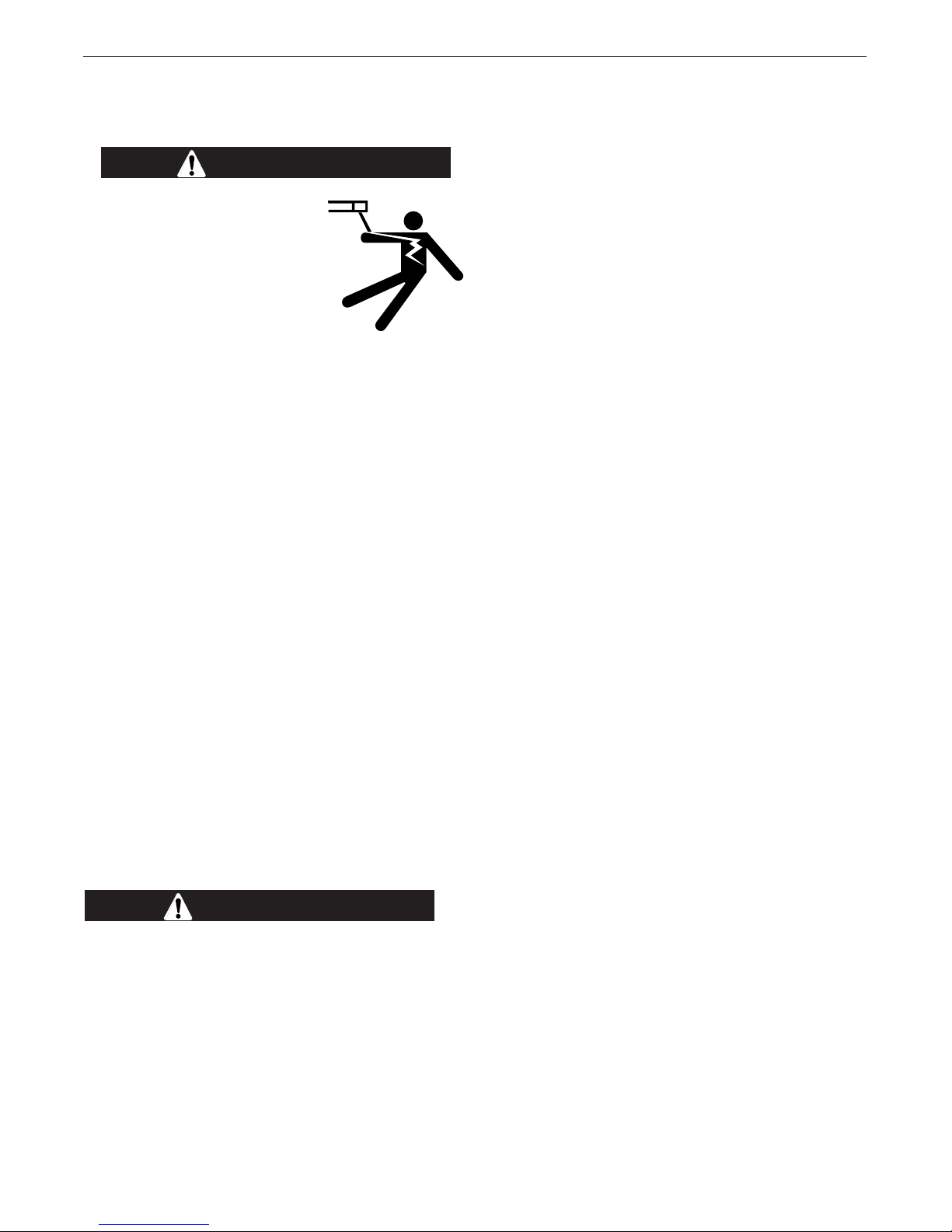
1WARNING
This statement appears where the information must be followed
exactly to avoid serious personal injury or loss of life.
CAUTION
This statement appears where the information must be followed to
avoid minor personal injury or damage to this equipment.
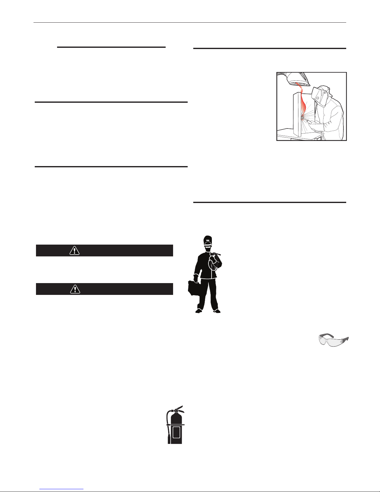
KEEP YOUR HEAD OUT OF THE FUMES.
DON’T get too close to the arc. Use corrective lenses if necessary to
stay a reasonable distance away from
the arc.
READ and obey the Material Safety
Data Sheet (MSDS) and the warning
label that appears on all containers of
welding materials.
USE ENOUGH VENTILATION or
exhaust at the arc, or both, to keep
the fumes and gases from your
breathing zone and the general area.
IN A LARGE ROOM OR OUTDOORS, natural ventilation may be
adequate if you keep your head out of the fumes (See below).
USE NATURAL DRAFTS or fans to keep the fumes away from your
face.
If you de velop unusual symptoms, see your supervisor. Perhaps the
welding atmosphere and ventilation system should be checked.
WEAR CORRECT EYE, EAR & BODY PROTECTION
PROTECT your eyes and face with welding helmet properly fitted and
with proper grade of filter plate (See ANSI Z49.1).
PROTECT your body from welding spatter and arc
flash with protective clothing including woolen
clothing, flame-proof apron and gloves, leather
leggings, and high boots.
PROTECT others from splatter, flash, and glare with
protective screens or barriers.
IN SOME AREAS, protection from noise may be
appropriate.
BE SURE protective equipment is in good condition.
Also, wear safety glasses in work area AT ALL
TIMES.
SPECIAL SITUATIONS
DO NOT WELD OR CUT containers or materials
which previously had been in contact with hazardous
substances unless they are properly cleaned. This is extremely
dangerous.
DO NOT WELD OR CUT painted or plated parts unless special
precautions with ventilation have been taken. They can release highly
toxic fumes or gases.
Additional precautionary measures
PROTECT compressed gas cylinders from excessive heat, mechanical
shocks, and arcs; fasten cylinders so they cannot fall.
BE SURE cylinders are never grounded or part of an electrical circuit.
REMOVE all potential fire hazards from welding area.
ALWAYS HAVE FIRE FIGHTING EQUIPMENT READY FOR IMMEDIATE
USE AND KNOW HOW TO USE IT.
2
Page 3

APEX® 3 SERIES MIG PENDANT MANUAL
SECTION A:
WARNINGS
1.d. Keep all equipment safety guards, covers and
devices in position and in good repair.Keep
hands, hair, clothing and tools away from
V-belts, gears, fans and all other moving parts
when starting, operating or repairing equipment.
SAFETY
SAFETY
CALIFORNIA PROPOSITION 65 WARNINGS
Diesel Engines
Diesel engine exhaust and some of its constituents are known
to the State of California to cause cancer, birth defects, and other
reproductive harm.
Gasoline Engines
The engine exhaust from this product contains chemicals known
to the State of California to cause cancer, birth defects, or other reproductive harm.
ARC WELDING CAN BE HAZARDOUS. PROTECT
YOURSELF AND OTHERS FROM POSSIBLE SERIOUS
INJURY OR DEATH. KEEP CHILDREN AWAY.
PACEMAKER WEARERS SHOULD CONSULT WITH
THEIR DOCTOR BEFORE OPERATING.
Read and understand the following safety highlights. For additional
safety information, it is strongly recommended that you purchase a
copy of “Safety in Welding & Cutting - ANSI Standard Z49.1” from the
American Welding Society, P.O. Box 351040, Miami, Florida 33135
or CSA Standard W117.2-1974. A Free copy of “Arc Welding Safety”
booklet E205 is available from the Lincoln Electric Company, 22801
St. Clair Avenue, Cleveland, Ohio 44117-1199.
BE SURE THAT ALL INSTALLATION, OPERATION,
MAINTENANCE AND REPAIR PROCEDURES ARE
PERFORMED ONLY BY QUALIFIED INDIVIDUALS.
1.e. In some cases it may be necessary to remove safety guards
to perform required maintenance. Remove guards only when
necessary and replace them when the maintenance requiring
their removal is complete. Always use the greatest care when
working near moving parts.
1.f. Do not put your hands near the engine fan. Do not attempt to
override the governor or idler by pushing on the throttle control
rods while the engine is running.
1.g. To prevent accidentally starting gasoline engines while turning
the engine or welding generator during maintenance work,
disconnect the spark plug wires, distributor cap or magneto wire
as appropriate.
1.h. To avoid scalding, do not remove the radiator
pressure cap when the engine is hot.
ELECTRIC AND MAGNETIC FIELDS
MAY BE DANGEROUS
2.a. Electric current flowing through any conductor
causes localized Electric and Magnetic Fields
(EMF). Welding current creates EMF fields
around welding cables and welding machines
FOR ENGINE POWERED
EQUIPMENT.
1.a. Turn the engine off before troubleshooting and
maintenance work unless the maintenance
work requires it to be running.
1.b. Operate engines in open, well-ventilated areas
or vent the engine exhaust fumes outdoors.
1.c. Do not add the fuel near an open flame welding arc or when the
engine is running. Stop the engine and allow it to cool before
refueling to prevent spilled fuel from vaporizing
on contact with hot engine parts and igniting.
Do not spill fuel when filling tank. If fuel is
spilled, wipe it up and do not start engine until
fumes have been eliminated.
2.b. EMF fields may interfere with some pacemakers, and welders
having a pacemaker should consult their physician before
welding.
2.c. Exposure to EMF fields in welding may have other health effects
which are now not known.
2.d. All welders should use the following procedures in order to
minimize exposure to EMF fields from the welding circuit:
2.d.1. Route the electrode and work cables together - Secure
them with tape when possible.
2.d.2. Never coil the electrode lead around your body.
2.d.3. Do not place your body between the electrode and work
cables. If the electrode cable is on your right side, the
work cable should also be on your right side.
2.d.4. Connect the work cable to the workpiece as close as possible to the area being welded.
2.d.5. Do not work next to welding power source.
3
Page 4
APEX® 3 SERIES MIG PENDANT MANUAL
SAFETY
SAFETY
ELECTRIC SHOCK
CAN KILL.
3.a. The electrode and work (or ground) circuits are
electrically “hot” when the welder is on. Do not
touch these “hot” parts with your bare skin or wet
clothing. Wear dry, hole-free gloves to insulate hands.
3.b. Insulate yourself from work and ground using dry insulation.
Make certain the insulation is large enough to cover your full area
of physical contact with work and ground.
In addition to the normal safety precautions, if
welding must be performed under electrically
hazardous conditions (in damp locations or while
wearing wet clothing; on metal structures such
as floors, gratings or scaffolds; when in cramped
positions such as sitting, kneeling or lying, if there
is a high risk of unavoidable or accidental contact
with the workpiece or ground) use the following
equipment:
• Semiautomatic DC Constant Voltage (Wire) Welder.
• DC Manual (Stick) Welder.
• AC Welder with Reduced Voltage Control.
3.c. In semiautomatic or automatic wire welding, the electrode,
electrode reel, welding head, nozzle or semiautomatic welding
gun are also electrically “hot”.
3.d. Always be sure the work cable makes a good electrical
connection with the metal being welded. The connection should
be as close as possible to the area being welded.
3.e. Ground the work or metal to be welded to a good electrical (earth)
ground.
3.f. Maintain the electrode holder, work clamp, welding cable and
welding machine in good, safe operating condition. Replace
damaged insulation.
3.g. Never dip the electrode in water for cooling.
3.h. Never simultaneously touch electrically “hot” parts of electrode
holders connected to two welders because voltage
the two can be the total of the open circuit voltage of both
welders.
3.i. When working above floor level, use a safety belt to protect
yourself from a fall should you get a shock.
3.j. Also see It ems 6.c. and 8.
between
ARC RAYS CAN BURN.
4.a. Use a shield with the proper filter and cover plates to protect
your eyes from sparks and the rays of the arc when welding or
observing open arc welding. Headshield and filter lens should
conform to ANSI Z87. I standards.
4.b. Use suitable clothing made from durable flame-resistant material
to protect your skin and that of your helpers from the arc rays.
4.c. Protect other nearby personnel with suitable, non-flammable
screening and/or warn them not to watch the arc nor expose
themselves to the arc rays or to hot spatter or metal.
FUMES AND GASES CAN
BE DANGEROUS.
5.a. Welding may produce fumes and gases
hazardous to health. Avoid breathing these
fumes and gases. When welding, keep your head out of the
fume. Use enough ventilation and/or exhaust at the arc to
keep fumes and gases away from the breathing zone. When
welding with electrodes which require special
ventilation such as stainless or hard facing (see
instructions on container or MSDS) or on lead or
cadmium plated steel and other metals or coatings
which produce highly toxic fumes, keep exposure
as low as possible and within applicable OSHA
PEL and ACGIH TLV limits using local exhaust
or mechanical ventilation. In confined spaces or
in some circumstances, outdoors, a respirator
may be required. Additional precautions are also
required when welding on galvanized steel.
5. b. The operation of welding fume control equipment is affected
by various factors including proper use and positioning of the
equipment, maintenance of the equipment and the specific
welding procedure and application involved. Worker exposure
level should be checked upon installation and periodically
thereafter to be certain it is within applicable OSHA PEL and
ACGIH TLV limits.
5.c. Do not weld in locations near chlorinated hydrocarbon vapors
coming from degreasing, cleaning or spraying operations. The
heat and rays of the arc can react with solvent vapors to form
phosgene, a highly toxic gas, and other irritating products.
5.d. Shielding gases used for arc welding can displace air and
injury or death. Always use enough ventilation, especially in
confined areas, to insure breathing air is safe.
cause
5.e. Read and understand the manufacturer’s instructions for this
equipment and the consumables to be used, including the
material safety data sheet (MSDS) and follow your employer’s
safety practices. MSDS forms are available from your welding
distributor or from the manufacturer.
5.f. Also see item 1.b.
4
Page 5
APEX® 3 SERIES MIG PENDANT MANUAL
SAFETY
SAFETY
WELDING AND CUTTING
SPARKS CAN CAUSE
FIRE OR EXPLOSION.
6.a. Remove fire hazards from the welding area.
If this is not possible, cover them to prevent the welding sparks
from starting a fire. Remember that welding sparks and hot
materials from welding can easily go through small cracks and
openings to adjacent areas. Avoid welding near hydraulic lines.
Have a fire extinguisher readily available.
6.b. Where compressed gases are to be used at the job site, special
precautions should be used to prevent hazardous situations. Refer
to “Safety in Welding and Cutting” (ANSI Standard Z49.1) and the
operating information for the equipment being used.
6.c. When not welding, make certain no part of the electrode circuit
is touching the work or ground. Accidental contact can cause
overheating and create a fire hazard.
6.d. Do not heat, cut or weld tanks, drums or containers until the
proper steps have been taken to insure that such procedures will
not cause flammable or toxic vapors from substances inside. They
can cause an explosion even though they have been “cleaned”.
For information, purchase “Recommended Safe Practices for the
Preparation for Welding and Cutting of Containers and Piping That
Have Held Hazardous Substances”, AWS F4.1 from the American
Welding Society (see address above).
6.e. Vent hollow castings or containers before heating, cutting or
welding. They may explode.
6.f. Sparks and spatter are thrown from the welding arc. Wear oil free
protective garments such as leather gloves, heavy shirt, cuffless
trousers, high shoes and a cap over your hair. Wear ear plugs
when welding out of position or in confined places. Always wear
safety glasses with side shields when in a welding area.
CYLINDER MAY EXPLODE IF
DAMAGED.
7.a. Use only compressed gas cylinders containing
the correct shielding gas for the process used
and properly operating regulators designed for
the gas and pressure used. All hoses, fittings,
etc. should be suitable for the application and
maintained in good condition.
7.b. Always keep cylinders in an upright position securely chained to
an undercarriage or fixed support.
7.c. Cylinders should be located:
• Away from areas where they may be struck or subjected
to physical damage.
• A safe distance from arc welding or cutting operations
and any other source of heat, sparks, or flame.
7.d. Never allow the electrode, electrode holder or any other
electrically “hot” parts to touch a cylinder.
7.e. Keep your head and face away from the cylinder valve outlet
when opening the cylinder valve.
7.f. Valve protection caps should always be in place and hand tight
except when the cylinder is in use or connected for use.
7.g. Read and follow the instructions on compressed gas cylinders,
associated equipment, and CGA publication P-l, “Precautions for
Safe Handling of Compressed Gases in
from the Compressed Gas Association 1235 Jefferson Davis
Highway, Arlington, VA 22202.
Cylinders,” available
6.g. Connect the work cable to the work as close to the welding area
as practical. Work cables connected to the building framework
or other locations away from the welding area increase the
possibility of the welding current passing through lifting chains,
crane cables or other alternate circuits. This can create fire
hazards or overheat lifting chains or cables until they fail.
6.h. Also see item 1.c.
6.I. Read and follow NFPA 51B “ Standard for Fire Prevention During
Welding, Cutting and Other Hot Work”, available from NFPA, 1
Batterymarch Park, PO box 9101, Quincy, Ma 022690-9101.
6.j. Do not use a welding power source for pipe thawing.
FOR ELECTRICALLY
POWERED EQUIPMENT.
8.a. Turn off input power using the disconnect
switch at the fuse box before working on the
equipment.
8.b. Install equipment in accordance with the U.S. National Electrical
Code, all local codes and the manufacturer’s recommendations.
8.c. Ground the equipment in accordance with the U.S. National
Electrical Code and the manufacturer’s recommendations.
Refer to http://www.lincolnelectric.com/
safety for additional safety information.
5
Page 6

APEX® 3 SERIES MIG PENDANT MANUAL
ELECTROMAGNETIC
COMPATIBILITY (EMC)
CONFORMANCE
Products displaying the CE mark are in conformity with European Community
Council Directive of 3 May 1989 on the approximation of the laws of the
Member States relating to electromagnetic compatibility (89/336/EEC). It
was manufactured in conformity with a national standard that implements a
harmonized standard: EN 60974-10
Electromagnetic Compatibility (EMC) Product Standard for Arc Welding
Equipment. It is for use with other Lincoln Electric equipment. It is designed
for industrial and professional use.
INTRODUCTION
All electrical equipment generates small amounts of electromagnetic
emission. Electrical emission may be transmitted through power lines or
radiated through space, similar to a radio transmitter. When emissions are
received by other equipment, electrical interference may result. Electrical
emissions may affect many kinds of electrical equipment; other nearby
welding equipment, radio and TV reception, numerical controlled machines,
telephone systems, computers, etc. Be aware that interference may result
and extra precautions may be required when a welding power source is used
in a domestic establishment.
INSTALLATION AND USE
The user is responsible for installing and using the welding equipment
according to the manufacturer’s instructions. If electromagnetic disturbances
are detected then it shall be the responsibility of the user of the welding
equipment to resolve the situation with the technical assistance of the
manufacturer. In some cases this remedial action may be as simple as
earthing (grounding) the welding circuit, see Note. In other cases it could
involve construction of an electromagnetic screen enclosing the power
source and the work complete with associated input filters. In all cases
electromagnetic disturbances must be reduced to the point where they are
no longer troublesome.
Note: The welding circuit may or may not be earthed for safety reasons according to national codes.
Changing the earthing arrangements should only be authorized by a person who is competent
to access whether the changes will increase the risk of injury, e.g., by allowing parallel welding
current return paths which may damage the earth circuits of other equipment.
ASSESSMENT OF AREA
Before installing welding equipment the user shall make an assessment of
potential electromagnetic problems in the surrounding area. The following
shall be taken into account:
a. other supply cables, control cables, signaling and telephone cables; above, below
and adjacent to the welding equipment;
b. radio and television transmitters and receivers;
c. computer and other control equipment;
d. safety critical equipment, e.g., guarding of industrial equipment;
e. the health of the people around, e.g., the use of pacemakers and hearing aids;
f. equipment used for calibration or measurement
g. the immunity of other equipment in the environment. The user shall ensure that
other equipment being used in the environment is compatible. This may require
additional protection measures;
h. the time of day that welding or other activities are to be carried out.
SAFETY
The size of the surrounding area to be considered will depend on the
structure of the building and other activities that are taking place. The
surrounding area may extend beyond the boundaries of the premises.
METHODS OF REDUCING EMISSIONS
Mains Supply
Welding equipment should be connected to the mains supply according
to the manufacturer’s recommendations. If interference occurs, it may be
necessary to take additional precautions such as filtering of the mains supply.
Consideration should be given to shielding the supply cable of permanently
installed welding equipment, in metallic conduit or equivalent. Shielding
should be electrically continuous throughout its length. The shielding should
be connected to the welding power source so that good electrical contact is
maintained between the conduit and the welding power source enclosure.
Maintenance of the Welding Equipment
The welding equipment should be routinely maintained according to the
manufacturer’s recommendations. All access and service doors and covers
should be closed and properly fastened when the welding equipment is
in operation. The welding equipment should not be modified in any way
except for those changes and adjustments covered in the manufacturers
instructions. In particular, the spark gaps of arc striking and stabilizing
devices should be adjusted and maintained according to the manufacturer’s
recommendations.
Welding Cables
The welding cables should be kept as short as possible and should be
positioned close together, running at or close to floor level.
Equipotential Bonding
Bonding of all metallic components in the welding installation and adjacent
to it should be considered. However, metallic components bonded to the
work piece will increase the risk that the operator could receive a shock by
touching these metallic components and the electrode at the same time. The
operator should be insulated from all such bonded metallic components.
Earthing of the Workpiece
Where the workpiece is not bonded to earth for electrical safety, not
connected to earth because of its size and position, e.g., ships hull or
building steelwork, a connection bonding the workpiece to earth may reduce
emissions in some, but not all instances. Care should be taken to prevent the
earthing of the work piece increasing the risk of injury to users, or damage
to other electrical equipment. Where necessary, the connection of the
workpiece to earth should be made by a direct connection to the work piece,
but in some countries where direct connection is not permitted, the bonding
should be achieved by suitable capacitance, selected according to national
regulations.
Screening and Shielding
Selective screening and shielding of other cables and equipment in the
surrounding area may alleviate problems of interference. Screening of the
entire welding installation may be considered for special applications.
1 Portions of the preceding text are contained in EN 60974-10: “Electromagnetic
Compatibility (EMC) product standard for arc welding equipment.”
6
Page 7
APEX® 3 SERIES MIG PENDANT MANUAL
SAFETY
7
Page 8

APEX® 3 SERIES MIG PENDANT MANUAL
TABLE OF CONTENTS
Safety ....................................................................................................................................................... 2
Symbols & Icons ................................................................................................................................... 10
Safety Precautions ............................................................................................................................... 11
Proper handling .................................................................................................................................11
Operation ............................................................................................................................................... 11
Explanation of Welding Terms ........................................................................................................... 11
System Start Up .............................................................................................................................. B-1
Startup Screen ......................................................................................................................... B-1
Pendant Operation ................................................................................................................... B-2
Button Actions .......................................................................................................................... B-2
Selection Buttons ..................................................................................................................... B-2
Navigation Controls .................................................................................................................. B-2
Menu Buttons ........................................................................................................................... B-3
Control Buttons ........................................................................................................................ B-3
Color Coding ............................................................................................................................ B-3
Fast Movement ......................................................................................................................... B-3
System Log In ................................................................................................................................. B-4
Fast Movement ......................................................................................................................... B-4
Log In Screen ........................................................................................................................... B-5
Idle Screen ...................................................................................................................................... B-6
Menu Option Variables ............................................................................................................. B-6
Idle Screen Buttons .................................................................................................................. B-7
Idle Screen Test/Weld Modes .........................................................................................................B-8
Weld Screen ............................................................................................................................. B-9
Weld Screen Buttons ................................................................................................................ B-9
Test Screen ............................................................................................................................... B-9
Test Screen Buttons ................................................................................................................. B-9
Jog Screen .................................................................................................................................... B-10
Jog Buttons ............................................................................................................................ B-11
Oscillation Screen ......................................................................................................................... B-12
Oscillation Buttons ................................................................................................................. B-13
Setup Menu .................................................................................................................................. B-14
Setup Screen Options ............................................................................................................ B-15
Track Setup ............................................................................................................................ B-15
Track Type .............................................................................................................................. B-15
Track Ring Size ....................................................................................................................... B-15
Pipe Size ................................................................................................................................. B-15
Heavy Wall Pipes .................................................................................................................... B-15
Positioner Setup ..................................................................................................................... B-15
Travel Setup Screen ............................................................................................................... B-16
Travel Pattern ........................................................................................................................ B-16
Process Setup Screen .................................................................................................................. B-17
Standard Process Options ..................................................................................................... B-17
Weave Process Options ......................................................................................................... B-17
Mode Select .................................................................................................................................. B-18
List Mode Select ..................................................................................................................... B-19
Advanced Process Setup ............................................................................................................ B-19
Advanced Options .................................................................................................................. B-19
Wave Controls ........................................................................................................................ B-19
Height/Sensitivity Recommendations .................................................................................... B-19
Start Settings ................................................................................................................................ B-20
End Settings .................................................................................................................................. B-20
8
Page 9

APEX® 3 SERIES MIG PENDANT MANUAL
TABLE OF CONTENTS
GMAW/FCAW Timing Diagram ..................................................................................................... B-21
Service Menu ............................................................................................................................... B-22
Version .................................................................................................................................... B-22
Motion .................................................................................................................................... B-22
Faults ...................................................................................................................................... B-23
Settings .................................................................................................................................. B-23
Input Test ................................................................................................................................ B-23
How to Take a Snapshot ........................................................................................................ B-24
Users ............................................................................................................................................. B-25
Fast Movement ....................................................................................................................... B-25
Adding Users .......................................................................................................................... B-25
Deleting Users ........................................................................................................................ B-26
Changing User Access ........................................................................................................... B-27
Log Out ................................................................................................................................... B-27
Operator Log In ...................................................................................................................... B-27
Increments Settings ...................................................................................................................... B-28
Increment Options .................................................................................................................. B-28
Increment Reference .............................................................................................................. B-29
Programs ..................................................................................................................................... B-30
Fast Movement ....................................................................................................................... B-30
Saving an Independent Pass .................................................................................................. B-30
Saving a Program Base .......................................................................................................... B-31
Saving a Program Pass .......................................................................................................... B-31
Saving Program Updates ....................................................................................................... B-32
Hide Program Passes ............................................................................................................. B-33
Saving to a USB ..................................................................................................................... B-33
Copy to/from USB .................................................................................................................. B-33
Deleting a Program ................................................................................................................. B-34
Deleting a Program Base ........................................................................................................ B-34
Loading a Program ................................................................................................................. B-34
Overwriting a Program ........................................................................................................... B-35
Standard Piping Schedule Chart .......................................................................................................... 36
Wiring Diagram ...................................................................................................................................... 37
Parts ....................................................................................................................................................... 38
9
Page 10
APEX® 3 SERIES MIG PENDANT MANUAL
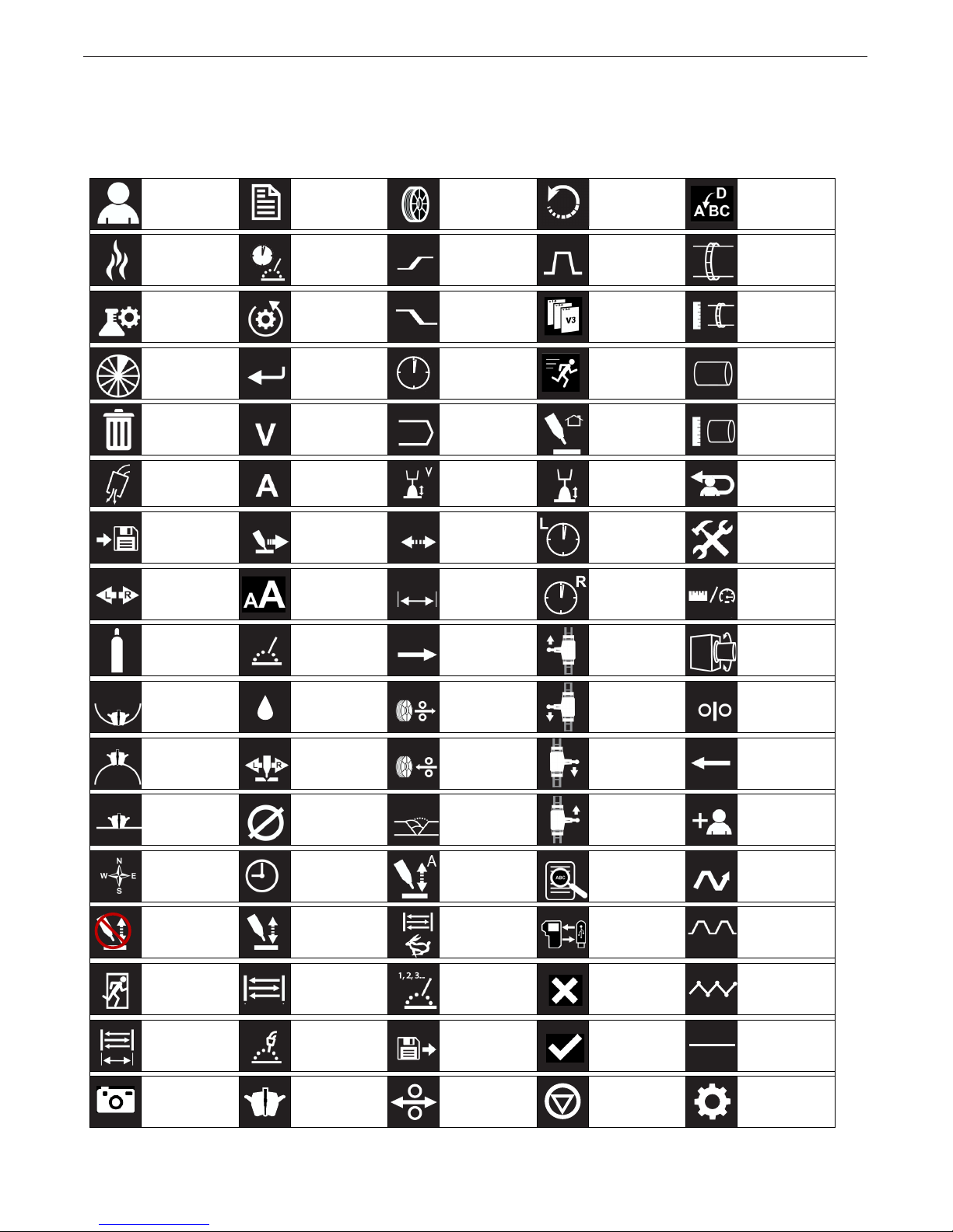
Symbols & Icons
This list is a quick reference for all icons from the
pendant and on the control unit.
OPERATION
Users Set Up/
Modes
Weld Weld Time Upslope /
Test Mode Reset
Settings
Segment Enter Time Motion Pipe
Trash Voltage Program Return Home Pipe
Gas Purge
Pre/Post Flow
Save Travel /
Swap Shift Case Osc Width Right Dwell Increment
Gas Advanced
Amperage Trim Volts Trim Log Out
Travel Setup
Settings
Wire Reboot Insert
Process Track Ring
Start Settings
Downslope /
End Settings
Osc Speed Left Dwell Settings /
Next /
Index
Version Track Ring
Diameter
Diameter
Service Page
Unit Settings
Travel
Direction
Positioner
ID Track
OD Track Steering /
Flat Track Wire Diam-
Direction Delay Amps Details Weave
Manual
Height
Exit Oscillation Mode
Oscillation
Width
Snapshot
Kilowatts Wire Feed Travel
Water
K
Wire
Oscillator
eter
Torch/Auto
Height
Weld Mode Load Okay No Weave
Weld Head Wire On Faults
Retract
Pass Travel
Oscillation
Speed
Select
Direction
Travel
Direction
Direction
Copy To Constant
Cancel Step
Wire / Wire
Feed Speed
Previous /
Index
Add User
Type
Travel
Travel
Travel
Settings
10
Page 11
APEX® 3 SERIES MIG PENDANT MANUAL
OPERATION
Safety Precautions
Read entire manual before installation or operation.
WARNING
ELECTRIC SHOCK CAN KILL
• Only qualied personnel
should perform this
installation.
• Turn the input power OFF at
the disconnect switch or fuse
box before working on this
equipment turn off the input
power to any other equipment
connected to the welding system at the disconnect switch or fuse box before working on the
equipment.
• Do not touch electrically hot parts.
• Always connect the power supply grounding lug
to a proper safety (Earth) ground.
Proper handling
The APEX® 3 Series Pendant is designed to be turned
on and off through the welding power supply. The
pendant should be kept dry and sheltered from rain
and snow. Do not place or drop the pendant on wet
ground or in puddles. Always place the pendant on a
sturdy, at level surface when not in use and be sure to
unplug it.
Keep hands away from weld head, wire feeder and
other moving parts while in operation. Read this entire
process and operations manual before using the
equipment.
OPERATION
Explanation of Welding Terms
GMAW: Gas Metal Arc Welding
FCAW: Flux Cored Arc Welding
STT: Surface Tension Transfer
WFS: Wire Feed Speed
OSC: Oscillation
ACC: Automatic Current Control
AHC: Automatic Height Control
ID: Inside Diameter
OD: Outside Diameter
WFS: Wire Feed Speed
IPM: Inches per minute
CM/MIN: Centimeters per minute
Volts: Voltage
Amps: Amperage
Only operate the system while on a rm level surface.
Always verify that the system cart is secured in place
before operating the system.
Keep hands away from weld head, wire feeder and
other moving parts while in operation.
CAUTION
Never unplug or plug in control cables to the weld
head while the system is powered on.
Verify that the system is properly grounded before
beginning to weld.
Refer to the individual components manuals for additional instructions.
11
Page 12
APEX® 3 SERIES MIG PENDANT MANUAL
System Start Up
Ensure all components are connected. Refer to the
individual component manuals for full connection
instructions.
Prior to beginning the weld, turn on the welding
power supply. The system is designed to be turned
on and off through the welding power supply.Ensure
all components are connected. Refer to the individual
component manuals for full connection instructions.
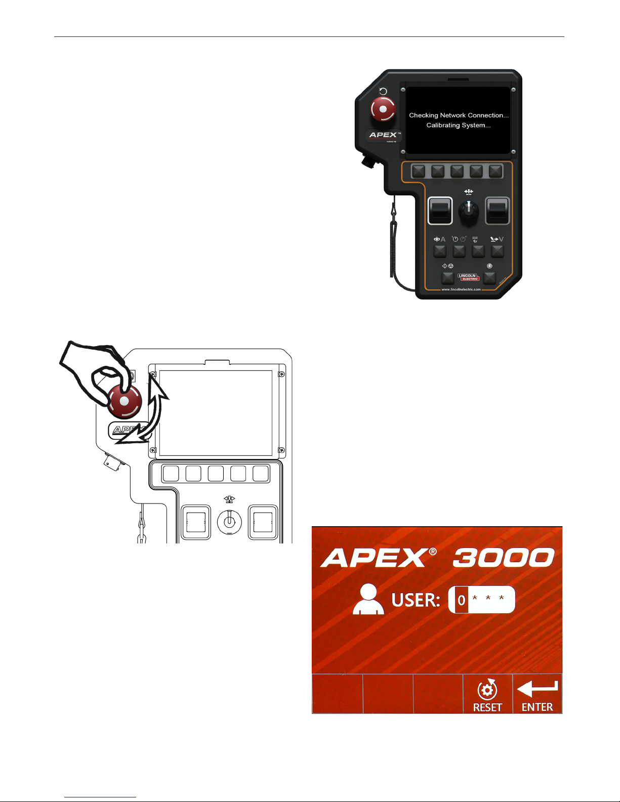
Note: With power applied to the system, check the
reset button. If the reset button is engaged
the system will not initialize. To disengage the
reset button, rotate the knob clockwise. See
FIGURE 1 - APEX Pendant Reset Button.
This reset button can be used to restart the system
for troubleshooting purposes and to halt welding and
system movement.
OPERATION
FIGURE 2 - Startup Screen
Startup Screen
When the system is reset at the Power Wave®, the
screen will display “Checking Network Connection...
Calibrating System – FIGURE 2 - Startup Screen.
This is a normal part of the initialization process.
Note: During the start up interval, the weld head goes
through a self-calibration cycle. The system will
not allow the user to log in until the calibration
cycle has been completed.
When the system is fully calibrated, the user is presented with a log in screen – see FIGURE 3 - Log In
Screen. Log in to begin use. See the next sections for
pendant operation.
FIGURE 1 - Pendant Reset Button
FIGURE 3 - Log In Screen
B-1
Page 13

APEX® 3 SERIES MIG PENDANT MANUAL
OPERATION
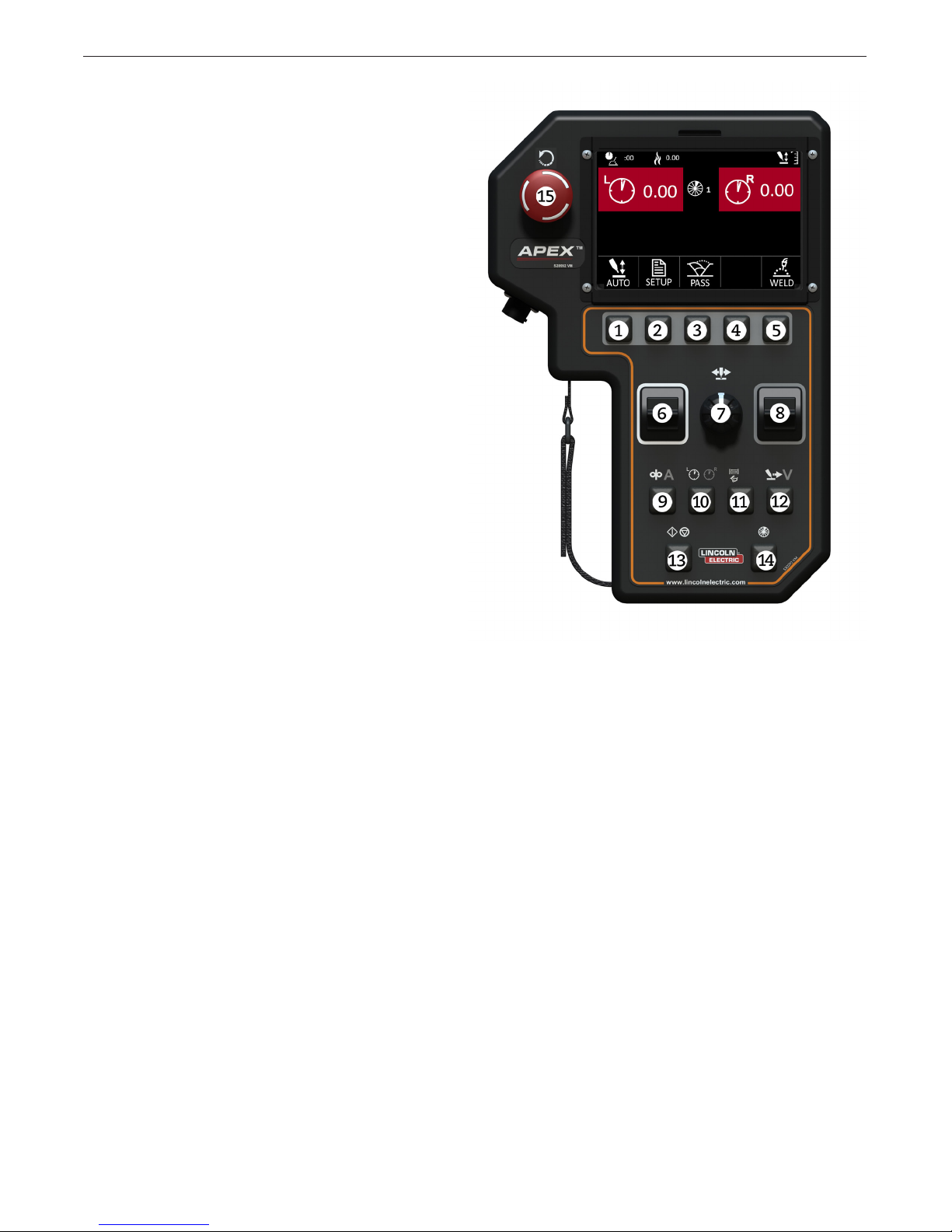
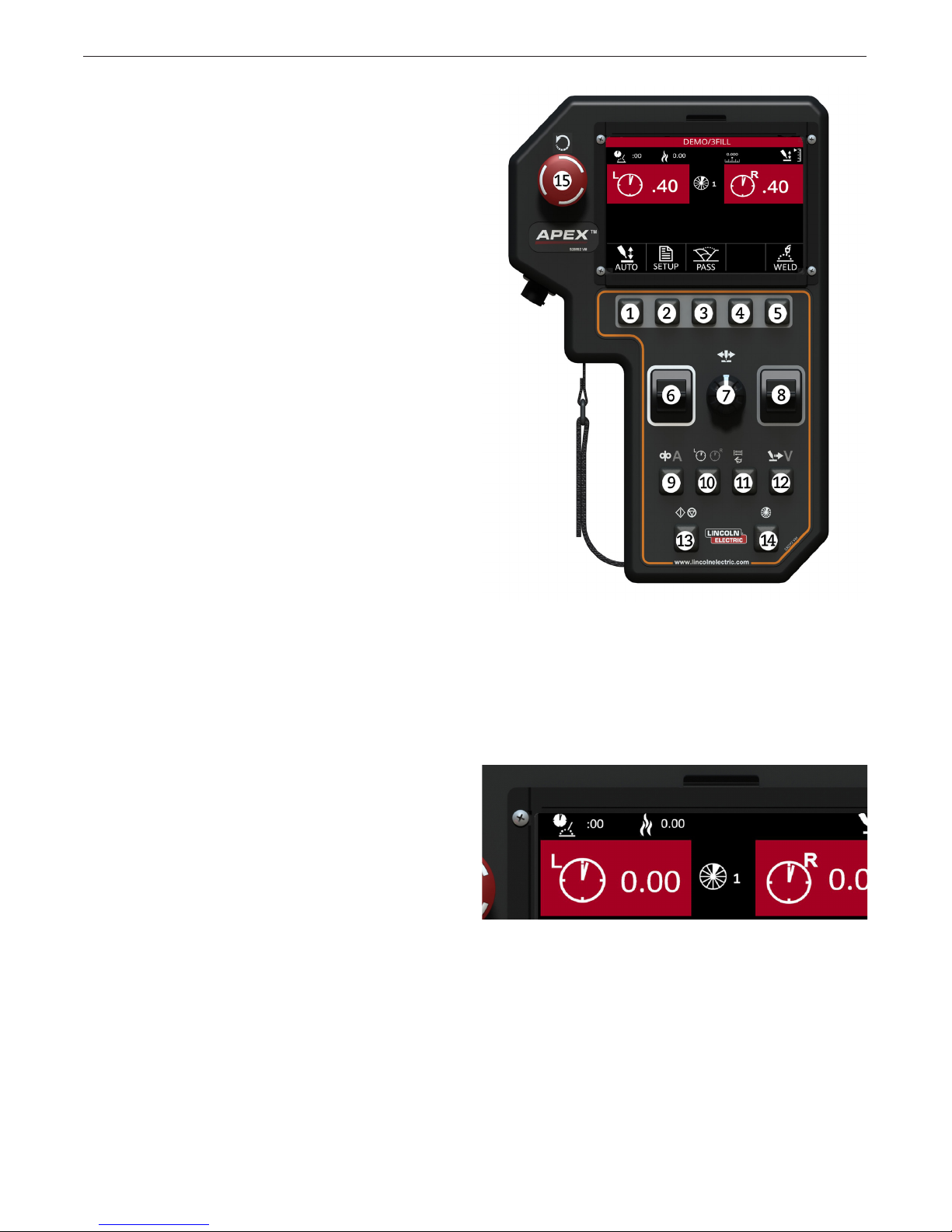
Pendant Operation
The APEX 3 Series Pendant is designed around full
functionality and easy operator experience. The pendant’s buttons serve multiple purposes, depending on
the screen display. See FIGURE 4 - Pendant Items on
page B-3 – to review each button, knob and switch on
the pendant.
Button Actions
Each of the buttons and toggles may perform
differently depending on how the buttons are pressed.
Listed below are the four types of button presses.
1. SHORT PRESS
A short press is a standard press that engages the
button and is not held in place. Most operations are
performed as a short press.
Example: Quickly pressing down button 7 will center the
oscillator.
2. LONG PRESS
For some screens, holding a button down for a
length of time exceeding two seconds signals the
system to perform an alternate function.
Example: A long press of more than two seconds on button 7 will start the oscillation test mode on some screens.
3. HOLD
By pressing and holding down a button or toggle,
the effects exhibited will continue or speed up.
Example: When pressing button 1 in the jog screen,
gas will purge for three seconds. Holding down button 1
will cause the gas to continuously purge.
4. HOLD AND ROTATE
The steering knob also acts as a button. It can be
pressed or rotated for different actions for some
screens. It can also be held down and rotated
for faster navigation.
6. LEFT TOGGLE (WHITE BORDER)
• Short Press – Navigates or changes the selected
value (in this example, it will change the value in
the left dwell box)
• Hold – Increases or decreases value / change
speed on some screens
7. STEERING KNOB
• Rotate – Steers oscillation in and out or changes
the selected variable
• Short Press – Centers the oscillation or moves to
the next variable
• Long Press – Starts / Stops oscillation test
(in idle mode only)
• Hold & Rotate – Fast navigation between
selected variables
8. RIGHT TOGGLE (GRAY BORDER)
• Short Press – Navigates or changes the selected
value (in this example, it will change the value in
the right dwell box)
• Hold – Increases or decreases value / changes
speed on some screens
Selection Buttons
Buttons 1 through 5 are selection buttons. Their
functions change depending on the screen. In each
screen there will be an icon just above the button to
indicate its function. A short press enables, disables or
selects the shown variable.
Navigation Controls
Items 6 through 8 control navigation. They function
primarily for navigating through the menus and
changing values while setting up the system.
Note: When welding, steering knob 7 functions
only for steering or oscillation steering
if oscillation is enabled.
B-2
Page 14
APEX® 3 SERIES MIG PENDANT MANUAL
Menu Buttons
Buttons 9 through 12 are the menu buttons. Pressing
one of these buttons will bring up a menu while in the
idle, test or welding screens.
9. WIRE FEED/AMPS
• Short Press – Wire Feed/Amps options
• Long Press – Navigates to the Jog Screen from
the Idle Weld screen
10. DWELL
• Short Press – Dwell options
• Long Press – Navigates to the Oscillation Screen
from the Idle Weld screen
11. OSCILLATION
• Short Press – Oscillation options
• Long Press – Navigates to the Oscillation Screen
from the Idle Weld screen
12. TRAVEL/VOLTS
OPERATION
• Short Press - Travel/voltage options
• Long Press - Navigates to the jog screen
from the idle weld screen
Control Buttons
Buttons 13 through 15 are the pendant control
buttons. These buttons have specic purposes that
typically do not change.
Note: The control buttons may be disabled in
menu screens.
13. START/STOP
• Short Press – Start if idle, stop if welding, stop/
start test weld when in test mode
14. SECTOR
• Short Press – Switches between sectors and
changes passes (if available) on the Increments
screen.
15. RESET –
• Short Press – stops the welding sequence
and all motion
• Twist Release
IMPORTANT! The reset button is not an emergency
stop button. Power is still being applied to the system.
FIGURE 4 - Pendant Items
Color Coding
The menu buttons and toggles are color-coded. For
example, the icons above button 9 are Wire Feed
(white icon) and Amps (gray icon). When the operator
presses the 9 button in the weld (idle) screen, the value
for the Wire Feed (white icon) will be presented and
can be changed by the left toggle (white border) and
the value for Amps (gray icon) will be presented and
can be changed by the right toggle (gray border).
Fast Movement
Certain screens allow for fast movement using the
steering knob. Movement and selection can still be
accomplished with the left and right toggle. In addition
the steering knob will allow the user to change the
selection by turning the knob and moving to the next
section by pressing the knob.
For fast movement between selections hold the steering knob down while turning to rapidly move from one
selection to the other.
B-3
Page 15
APEX® 3 SERIES MIG PENDANT MANUAL
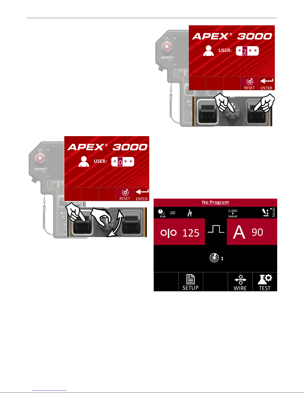
System Log In
When powered on, the system will go through a
self-calibration routine. Make sure the torch is free to
move before starting the system.
When the calibration routine is complete, the user
will be presented with a Log In Screen – see FIGURE
3 - Log In Screen on page B-1 and FIGURE 6 Change User. The system requires a four-digit user
code to log in.
Fast Movement
Fast movement using the steering knob is enabled on
this screen – see FIGURE 5 - Fast Movement. Use
the steering knob or left and right toggles for navigation and selection.
OPERATION
FIGURE 6 - Change User
Press the Enter Selection button when the complete
four digit user code has been entered. Once a four digit code is accepted, the system automatically moves
into the default Idle screen – see FIGURE 7- Idle
Screen Default. This screen is shown when a supervisor logs into the system. Logging in as an operator will
default to the Program Load Screen.
FIGURE 5 - Fast Movement
Use the left toggle or press the steering knob to
change from one variable to the next. Use the right
toggle or turn the steering knob to change the selected
variable.
FIGURE 7 - Idle Screen Default
B-4
Page 16
APEX® 3 SERIES MIG PENDANT MANUAL
OPERATION
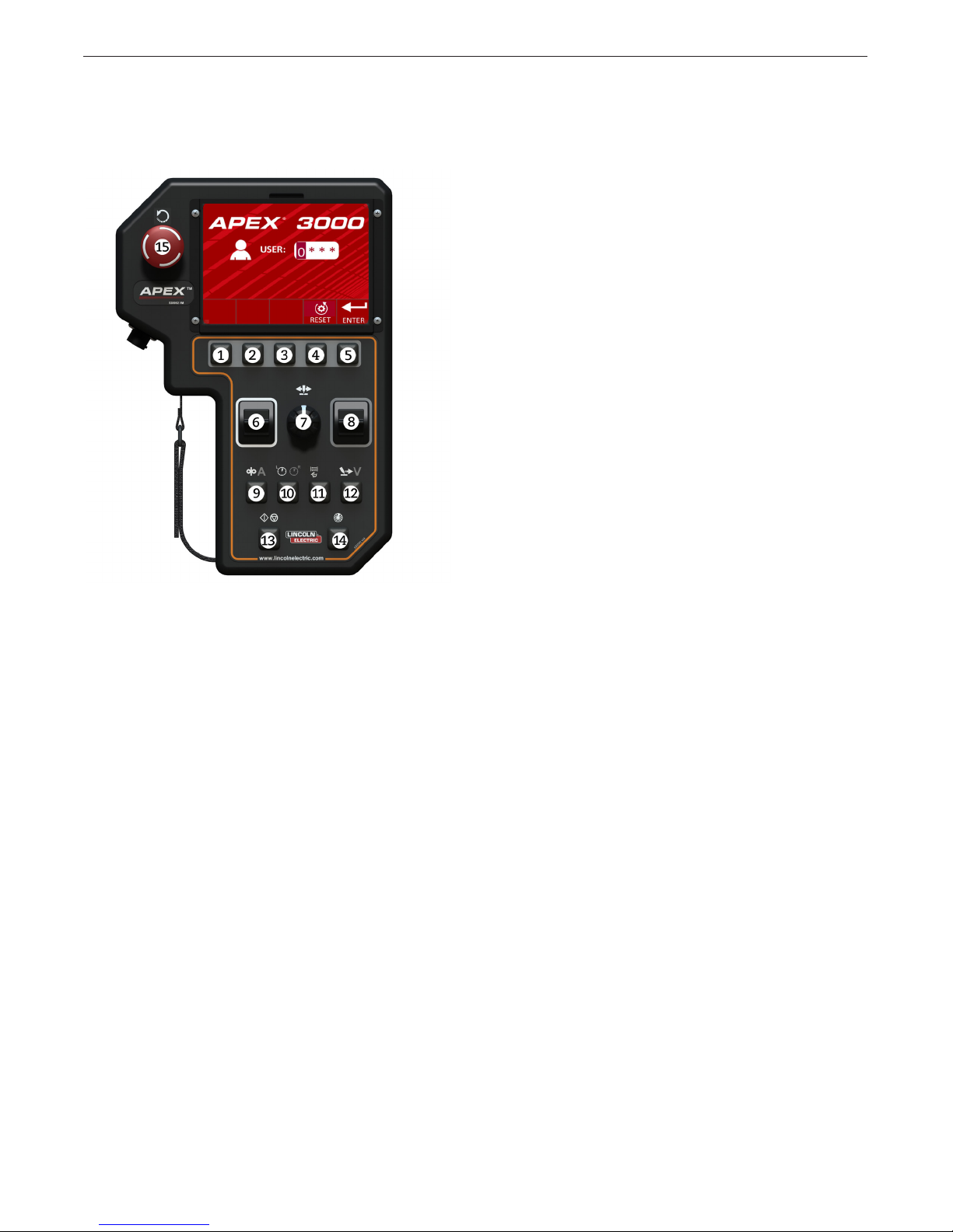
Log In Screen
The following buttons and options are available from
the log in screen – see FIGURE 8 - Log in Buttons.
7. STEERING KNOB
• Short Press – Moves cursor to the next space
• Rotation – Quickly cycles through available
character options
• Hold & Rotate – Quickly moves the cursor from
one selection to the next
8. RIGHT TOGGLE (Gray Border)
• Short Press – Pressing up or down changes
value of the selection
9. WIRE FEED/AMPS
• No Effect
10. DWELL
• No Effect
11. OSCILLATION
• No Effect
12. TRAVEL/VOLTs
• No Effect
13. START/STOP
• No Effect
FIGURE 8 - Log in Buttons
1. N/A
• No Effect
2. N/A
• No Effect
3. N/A
• No Effect
4. RESET
• Short Press – Will change password entry back
to “0000”
5. ENTER
• Short Press – Attempts to log in to the system
with the currently entered user code
6. LEFT TOGGLE (White Border)
• Short Press – Pressing up or down moves cursor
between spaces
14. SECTOR
• No Effect
15. Short Press – stops the welding sequence
and all motion
• Twist Release
B-5
Page 17
APEX® 3 SERIES MIG PENDANT MANUAL
OPERATION
Idle Screen
The Idle Screen is the rst screen presented to a
supervisor when logging in – see FIGURE 7 - Idle
Screen Default on page B-4. This screen allows the
supervisor to set up all parameters for welding, test the
parameters if necessary and to start welding.
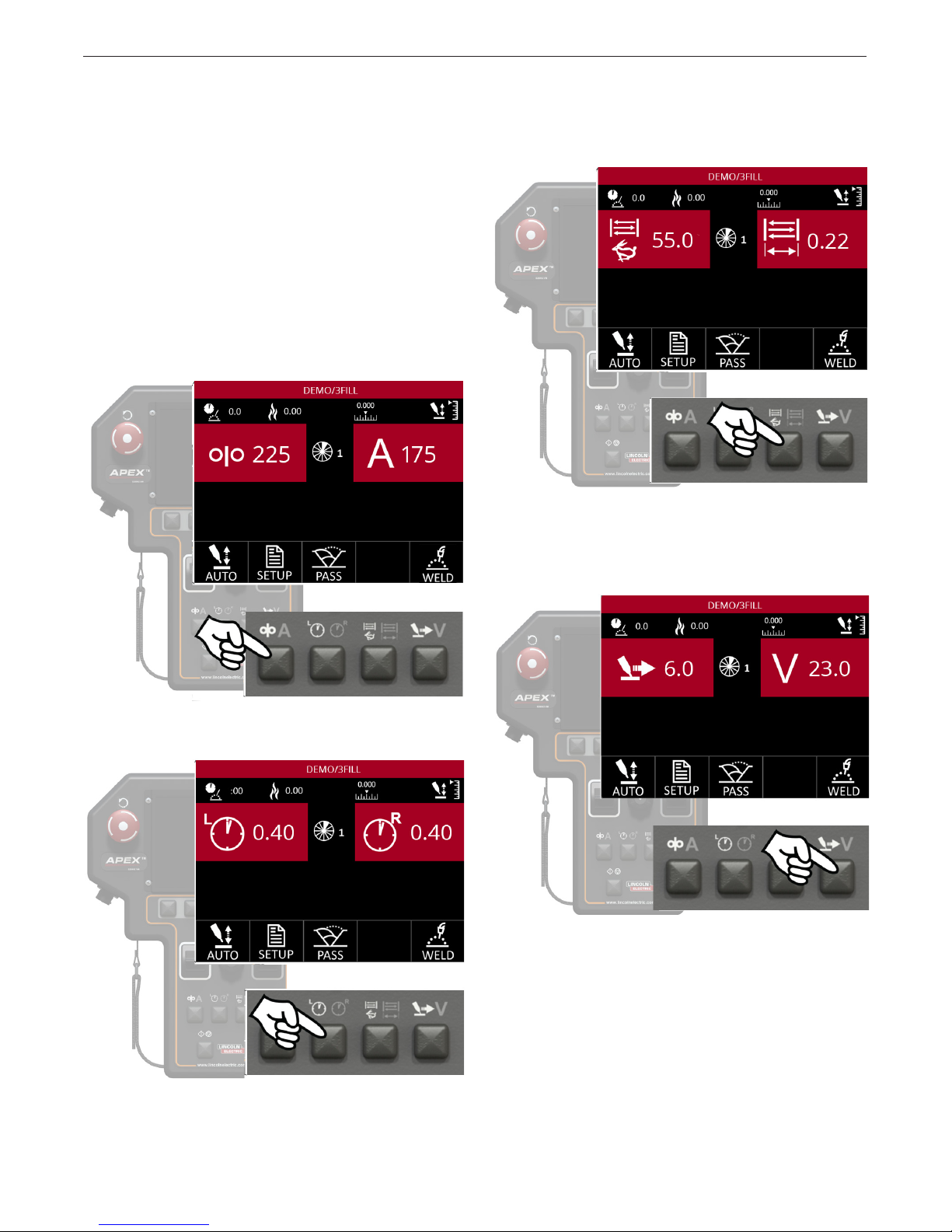
Menu Option Variables
The Idle Screen will show the user eight variables (two
variables on four separate screens), depending on
which Menu button has been pressed. Pressing the
different Menu buttons will change the values shown.
The different variables shown correspond to the icons
on the Menu buttons.
Similar variables are paired together. The variables
shown on the screen can be changed using the left
and right toggles. It is possible to change between
these menu options while idle or welding.
Press the Menu button to open the
Oscillation Menu options
Press the Menu button to open
the Wire Feed/Amps Menu options
Press the Menu button to open
the Dwell Menu options
Press the Menu button to open
the Travel/Voltage Menu options
B-6
Page 18
APEX® 3 SERIES MIG PENDANT MANUAL
Idle Screen Buttons
The Idle Screen – see FIGURE 9 – will change depending on which menu button has been selected. Some
items in the Selection button windows will change
depending on system congurations.
1. AUTO HEIGHT
• Short Press – Turns Auto Height on and off in
weld mode
2. SETUP
• Short Press – Navigates to the Setup Screen
3. PASS
• Short Press – Switches to the next pass in the
weld program (if available)
4. N/A
• No Effect
5. TEST/WELD
• Short Press – Switches between weld and test
modes (Image shows system in Weld Mode)
OPERATION
6. LEFT TOGGLE (White Border)
• Changes the value displayed in the top left box
(in this example it will change the value in the left
dwell box)
7. STEERING KNOB
• Rotate – Moves the oscillation in and out
• Short Press – Centers the oscillation
• Long Press – Starts/stops oscillation test
8. RIGHT TOGGLE (Gray Border)
• Changes the value displayed in the top right box
(in this example it will change the value in the right
dwell box)
9. WIRE FEED/AMPS
• Short Press – Wire Feed/Amps options
• Long Press – Navigates to the Jog Screen
10. DWELL
• Short Press – Dwell options
• Long Press – Navigates to the Jog Screen Dwell
11. OSCILLATION
• Short Press – Oscillation options
• Long Press – Navigates to the Jog Screen
Oscillation
12. TRAVEL/VOLTS
• Short Press – Travel/Voltage options
• Long Press – Navigates to the Jog Screen
Figure 9 - Idle Screen
13. START/STOP
• Short Press – Starts or stops welding or testing
14. SECTOR
• Short Press – Switches to the next sector if
multiple sectors are enabled
Current sector is displayed here at the center of the screen
near the sector icon.
15. Short Press – stops the welding sequence
and all motion
• Twist Release
* Important! This is not an emergency stop button.
Power is still being applied to the system. The system
will ask you to wait as it resets.
B-7
Page 19
APEX® 3 SERIES MIG PENDANT MANUAL
OPERATION
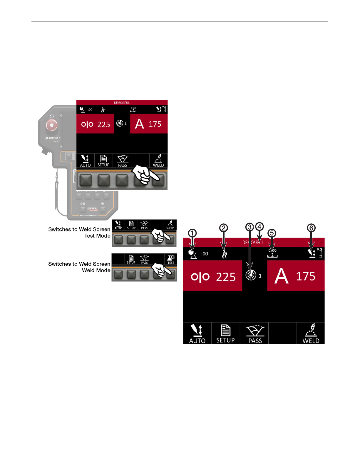
Idle Screen Test/Weld Modes
After preparing a program, it is recommended that
the user test the parameters before striking an arc.
The system allows for a test mode of all non-weld
functions such as travel, gas purge/ow, oscillation
and others.
Press the Weld/Test Selection button.
Static Screen Items
There are many icons common through the Idle, Weld
and Test screens. These items give helpful information
to the user throughout the setup and welding process.
1. Arc Time – Indicates the amount of time spent
welding
2. Heat Input – Displays the amount of heat input
for the current weld in kilojoules/in or
kilojoules/cm.
3. Sector – Displays the current sector in the weld
program, if applicable
4. Program Name – Displays the currently loaded
weld program and program pass.
Note:
Program Name changes to Italics when
program parameters have changed.
5. Oscillation Location – Displays the relative location
of the oscillation axis.
This example shows how to change the system from
the Test Mode to the Weld mode. The icon in the
Selection Button window indicates what mode the
system is in.
Note:
Auto Height is not an option while in Test Mode.
Pressing the Start/Stop Control Button will switch the
pendant from the Idle Screen to the Test Screen or
Weld Screen depending on which mode the user is in.
6. Torch Height – Displays the relative location of the
height axis.
FIGURE 10 - Static Items
The screen shot above – FIGURE 10 - Static Items
– illustrates the icons that appear on the weld screen.
These icons are for information only and are not
selectable variables.
B-8
Page 20

APEX® 3 SERIES MIG PENDANT MANUAL
OPERATION
Weld Screen
During the weld, the screen will show voltage and
amperage feedback on the Weld Screen – see FIGURE
11 - Weld Screen Options. Pressing the menu buttons
will move the user through the Menu Option Variables
similar to FIGURE 13- All Test Screens.
The Setup Selection is replaced with the Adv Selection. Autoheight can also be engaged or disengaged.
See FIGURE 10 - Weld Screen Options.
Weld Screen Buttons
The Weld Screen buttons work similar to the Idle
screen buttons – see Idle Screen section on page
B-7.
Pressing the Start/Stop button during the weld halts
the weld and moves into the Jog Menu. See FIGURE
16 on page B-11.
Test Screen
Similar to the Weld Screen, the Test Screen will show
voltage and amperage feedback but the feedback
values will be zero – FIGURE 12 - Test Screen
Options. Pressing the menu buttons will move the user
through the Menu Option Variables as shown in the
Idle Screen section.
FIGURE 11 - Weld Screen Options
FIGURE 12 - Test Screen Options
Test Screen Buttons
The Test Screen buttons work similar to the Weld
screen buttons – see FIGURE 13 - All Test Screens.
FIGURE 13 - All Test Screens
B-9
Page 21

APEX® 3 SERIES MIG PENDANT MANUAL
OPERATION
Jog Screen
The Jog Screen – FIGURE 15 - Jog Menu Screen –
is used to test movement of the system before welding. The Jog Screen can be entered from the Idle or
Oscillation screens.
From the Idle Screen, press and hold the Wire Feed/
Amps or the Travel/Voltage menu buttons to enter the
Jog Menu.
Press the Exit selection button to return Idle screen as
shown below.
FIGURE 14 - Engaging Jog Mode
The screen above – FIGURE 14 - Engaging Jog Mode
– provides for moving the weld head along the track,
adjusting torch height, purging gas and shows the
icons for both cold feed forward and cold feed reverse.
B-10
Page 22

APEX® 3 SERIES MIG PENDANT MANUAL
Jog Buttons
The following buttons and options are available from
the Jog Menu.
1. GAS PURGE
• Short Press – Purge welding gas for 3 seconds
• Hold – Continually purges welding gas while held
2. COLD FEED FORWARD
• Short Press – Feeds wire slightly
• Hold – Feeds wire continuously and accelerates
the WFS
3. COLD FEED REVERSE
• Short Press – Retracts wire slightly
• Hold – Retracts wire continuously and accelerates the WFS. Be sure to keep the spool tight as
wire is retracted
4. HOME
• Short Press – Returns the weld head to starting
position on the track. Starting position is determined by previous weld or test start.
OPERATION
5. EXIT
• Short Press – Returns to Idle Screen
6. LEFT TOGGLE (White Border)
• Short Press – Travels forward or backward
slightly
• Hold – Travels forward or reverse and ramps
travel speed
7. STEERING KNOB
• Rotate – Moves the oscillation in and out
• Short Press – Centers the oscillation
• Long Press – Starts/stops oscillation test
8. RIGHT TOGGLE (Gray Border)
• Short Press – Adjusts the torch up and down
• Hold – Adjusts the torch up and down and ramps
adjustment speed
9. WIRE FEED/AMPS
• No Effect
10. DWELL
• Short Press – Navigates to Jog Menu for
oscillation and dwell (short press does the same)
•
11. OSCILLATION
• Short Press – Navigates to Oscillation screen
FIGURE 15 - Jog Menu Screen
13. START/STOP
• If in TEST, it will run the TEST MODE; if in
WELD, the machine will start the weld
14. SECTOR
• No Effect
15. Short Press – stops the welding sequence
and all motion
• Twist Release
* Important! This is not an emergency stop button.
Power is still being applied to the system. The system
will ask you to wait as it resets.
12. TRAVEL/VOLTS
• No Effect
B-11
Page 23
APEX® 3 SERIES MIG PENDANT MANUAL
OPERATION
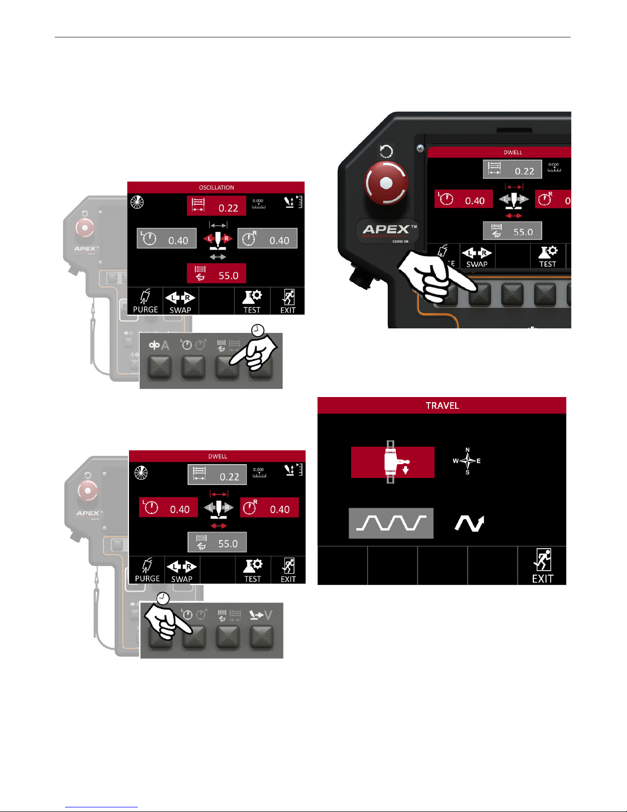
Oscillation Screen
The Oscillation Screen is used to test and adjust system oscillation before welding. To enter, press and hold
the Dwell or Oscillation menu buttons while in the Jog,
Idle or Weld screens.
From the Idle screen, pressing and holding the Oscillator Menu Button will present the user with the option to
change the oscillation width and the oscillation speed.
Press the Swap Selection Button to be taken to the
Travel Setup Screen.
Travel Setup is discussed in the Travel Setup Screen
section on page B-16. This screen allows the user to
quickly change weld head orientation or change the
weave pattern.
From the Idle screen, holding down the Dwell Menu
Button will present the user with the option to change
the left and right dwells.
In either screen, use a short press to switch between
Oscillation and Dwell. The items highlighted in red are
the variables that can be changed.
Press the “Exit” selection button to return to the Jog
Screens. Once all parameters have been input and
checked, exit out of the Jog Screen to return to the
Weld (also called the “Idle”) Screen.
B-12
Page 24
APEX® 3 SERIES MIG PENDANT MANUAL
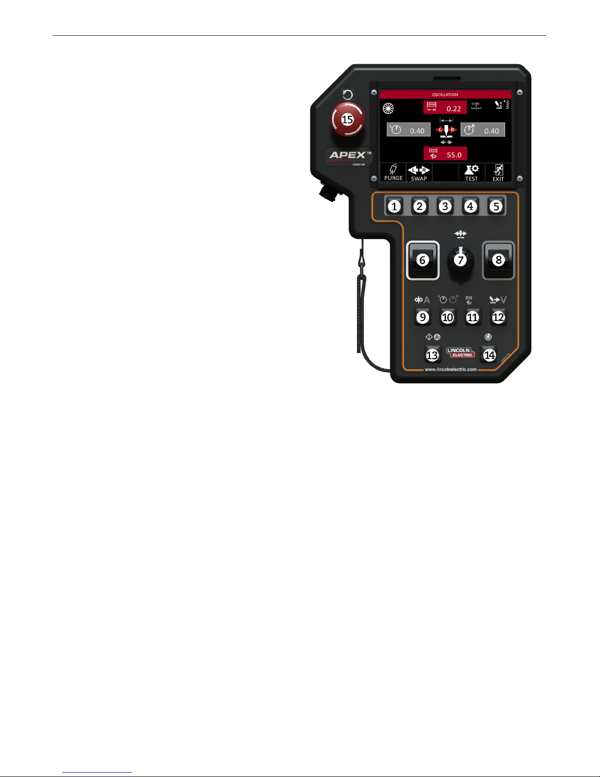
Oscillation Buttons
The following buttons and options are available from
the from the Oscillation menu:
1. PURGE
• Short Press – Purge welding gas for 3 seconds
• Hold – Continually purges welding gas while held
2. L/R SWAP
• Short Press – Navigates to the Travel Direction
Setup Screen
3. N/A
• No Effect
4. TEST/WELD
• Short Press – Starts/Stops oscillation test
5. Exit
• Short Press – Returns to Idle Screen
OPERATION
6. LEFT TOGGLE (White Border)
• Short Press – Increases or decreases Left Dwell
time or Oscillation Width
• Hold – Increases increment speed
7. STEERING KNOB
• Rotate – Moves the oscillation in and out
• Short Press – Centers the oscillation
• Long Press – Starts/stops oscillation test
8. RIGHT TOGGLE (Gray Border)
• Short Press – Increases or decreases Right Dwell
time or Oscillation Speed
• Hold - Increases or decreases value continuously
9. WIRE FEED/AMPS
• Short Press – Navigates to Jog Menu
10. DWELL
• Short Press – Switches to Dwell option (when in
Oscillation option, otherwise no effect)
11. OSCILLATION
• Short Press – Switches to Oscillation option
(when in Dwell option, otherwise no effect)
FIGURE 16 - Oscillation Screen
14. SECTOR
• Short Press – If multiple sectors are available,
a short press will move to the next available
sector and display the values associated with
that sector.
15. Short Press – stops the welding sequence
and all motion
• Twist Release
* Important! This is not an emergency stop button.
Power is still being applied to the system. The system
will ask you to wait as it resets.
12. TRAVEL/VOLTS
• Short Press – Navigates to Jog Menu
13. START/STOP
• Starts and stops TEST or WELD MODE
B-13
Page 25

APEX® 3 SERIES MIG PENDANT MANUAL
Setup Menu
The setup screen allows the user to access all
parameters for welding. Please note that this screen
can only be accessed by authorized supervisors set
up in the User’s Menu. This is explained further in the
User’s Setup Screen section.
The Setup Menu – see FIGURE 17 - Setup Menu –
can be accessed from the Weld Menu. This menu is
accessible in either test or weld mode, but it is not
accessible while welding. Press the Setup Selection
button to enter into the setup screen. Once in the
SetUp Menu, the user has access to multiple system
screens.
OPERATION
Setup Screen Options
Track Setup – employs internal or external track, at
track and the size of the pipe (where applicable).
Travel Setup – change the steering controls based on
where the operator is standing in relation to the track,
and set up the weave pattern.
Process Setup – sets up the weld process.
Start Settings – adjustment specic to the programs
affecting how the system will react when the weld
starts.
End Settings – adjustment specic to programs,
affecting how the system will react when the weld ends.
Service – access to current software information and
can change certain motion settings, as well as monitor
production, faults and tests.
Users – assigns operator and supervisor codes for the
system.
Increments – allows limits and the increment value
of each welding variable to be set. This screen also
enables the user to choose between imperial and
metric units.
Programs – The Programs screen is where all
programs are saved, loaded, deleted or copied.
FIGURE 17 - Setup Menu
To select the individual screens, the user moves the
red cursor to the desired eld using the Left Toggle
(White Border), and presses the Enter Selection button.
Pressing Exit will return the user back to the Idle screen.
B-14
Page 26
APEX® 3 SERIES MIG PENDANT MANUAL
OPERATION
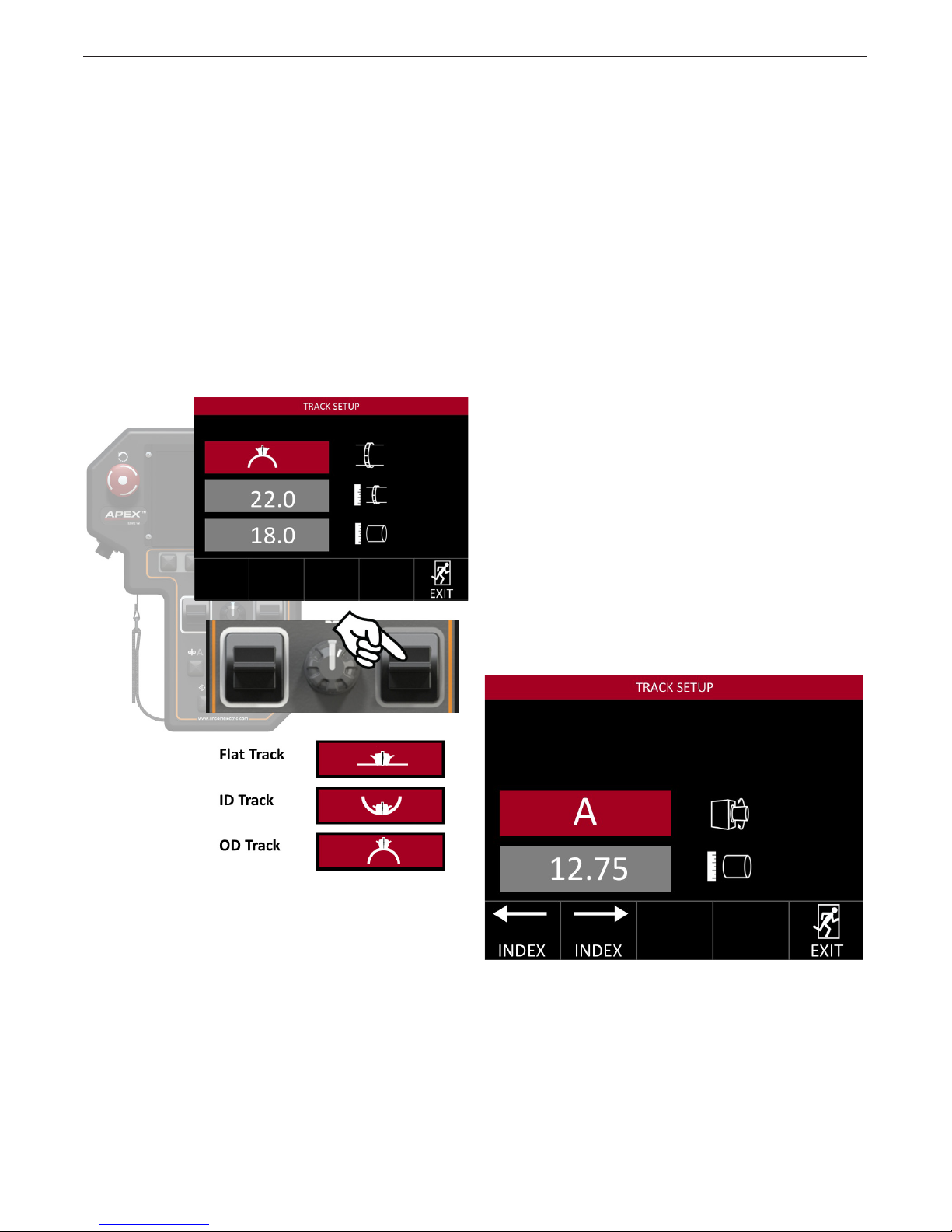
Track Setup
The Track Setup Screen presents the user with several options. From this screen the operator can change
the type of track, the size of the track and the size of
the pipe.
Track Type
The rst selectable option is track type. With the track
type eld highlighted in red the user is able to switch
between the different types of tracks. These tracks
consist of:
• Outside Diameter (OD) Track
• Inside Diameter (ID) Track
• Flat Track
The value can be adjusted in increments of 0.01 inches. Holding the right toggle for longer than 2 seconds
will amplify the speed at which the values increase.
Entering the correct value for track and pipe size
ensures accurate travel speed.
Heavy Wall Pipes
Heavy wall pipes may require the user to change the
pipe size in later passes.
Example: A 20 inch Schedule 120 pipe has an OD of
20 inches and an ID of 17 inches. The pipe diameter
for the root pass should be entered as 17.00 inches,
then increased as the weld progresses outward. This
will help to maintain an accurate welding travel speed
throughout the weld.
Note: For additional OD and ID pipe and tube size in-
formation, please refer to the “Standard Schedule Pipe
and Tube Chart” on page 36.
Positioner Setup
This system can be used as a part of a 1G system with
certain positioners. When the system detects positioners as part of the setup, the Travel Setup screen will
change. See FIGURE 18 - Track Setup Screen.
When the system is set to control multiple positioners
the right toggle will switch between positioner A and B.
Use the Index Selection buttons to index the weld
head on its mount.
Track Ring Size
Track sizes range from 4 to 100 inches in increments of
2 inches. Pressing and holding the right toggle will increase the speed at which the values change. Use the
nominal sizes for the track rings. THESE NOMINAL
SIZES ARE STAMPED INTO THE TRACK.
Pipe Size
The third eld that can be changed is the pipe size.
Currently this can range from 4 inches to 100 inches.
FIGURE 18 - Track Setup Screen
When the system is used to control positioners, the
weld screens will show the current positioner as a
selection. Pressing the Positioner Selection button will
switch from positioner A to positioner B.
B-15
Page 27

APEX® 3 SERIES MIG PENDANT MANUAL
OPERATION
Travel Setup Screen
The travel setup allows the supervisor to set how the
travel controls will work while welding and change the
weave pattern.
Travel
The operator has the option of choosing how the weld
head is oriented on the track. Setting the orientation
and travel direction allows for intuitive operation.
Travel Pattern
The second eld the operator can choose is the
weave pattern. There are three options to choose from:
With the travel eld highlighted, the weld head orientation and the travel direction can be selected. There
are four different options available. All directions refer
to the weld head and are in relation to the user’s view
facing the weld head.
1. Facing Right, Traveling Down
2. Facing Left, Traveling Down
3. Facing Right, Traveling Up
4. Facing Left, Traveling Up
No Weave
When no weave is selected, the oscillator does not
move during the welding process. The user can still
manually steer the oscillator.
Step Travel
During step travel, the travel speed stops during
the dwells. This allows the energy to be directed to
the side walls.
Continuous Travel
Continuous travel will continue travelling throughout the
weld process, during oscillation, excursion and dwells.
B-16
Page 28
APEX® 3 SERIES MIG PENDANT MANUAL
OPERATION
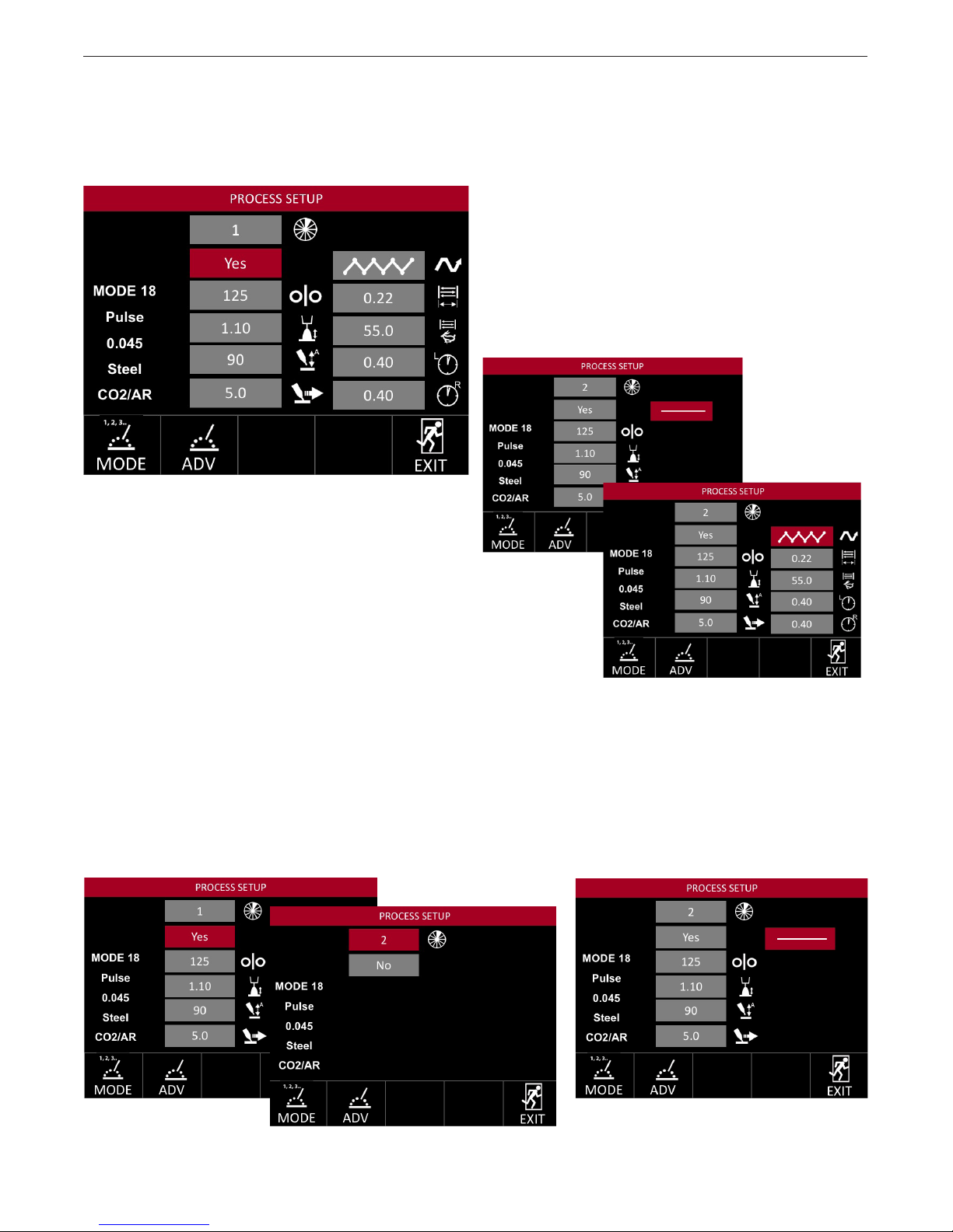
Process Setup Screen
The Process Setup Screen – see FIGURE 19 -
Process Setup – allows the user to select from several
options to determine the variables in the weld.
FIGURE 19 - Process Setup
Standard Process Options
Certain process options should be set up for every
weld and every sector. These options are:
• Sector – Determines which sector the options are
being set for out of eight possible sectors.
• Wire Speed – Sets wire feed speed
• Trim/Voltage – Controls the welding arc length.
• Torch Height (Amperage) – Controls the welding
amperage by raising or lowering the torch when
the Auto Height is turned on.
• Travel Speed – Sets the electrode travel speed
Enabling a sector presents the process variables for
that sector. With only one sector selected, the Idle,
Weld and Test screens will not show the sector icon.
Weave Process Options
• Weave – Refer to the Travel Pattern section on
page page B-16 for the different weave options.
• Oscillation Width – Determines the width of the
oscillation weave (limited by the weld head)
• Oscillation Speed – The speed at which the torch
moves during oscillation
• Left Dwell – How long the torch remains on the
left side of oscillation
• Right Dwell – How long the torch remains on the
right side of oscillation
The purpose of this screen is to set up base settings
before the weld begins. Without a weave selected,
oscillation settings will not appear on the screen.
B-17
Page 29
APEX® 3 SERIES MIG PENDANT MANUAL
OPERATION
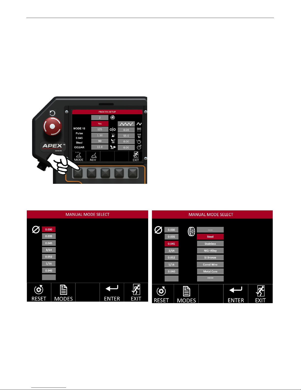
Mode Select
The weld mode is determined by the wire size, type,
process and type of gas being used. Refer to the Power Wave® operator’s manual for additional information
about weld modes. The system can be a guide when
the user is not sure which mode is appropriate for their
application.
Pressing the Mode selection button will take the user
to the Manual Mode Select Screen.
The user is prompted to select the wire size, type,
process and then gas type. Mode Select guides the
user through the settings. Selecting a wire diameter
moves to wire type. See FIGURE 20 - Manual Mode
Select.
Selecting wire type leads to a specic process and
then to gas selection.
Each selection lters the list of available weld modes
to match your application. A cored wire would not
allow the user to select an STT® process.
The selected mode is displayed on the left side of the
screen – see FIGURE 21 - List Mode Screen. These
processes are accessed from the Power Wave, and
are updated with the standard Power Wave updates.
FIGURE 20 - Manual Mode Select
B-18
Page 30
APEX® 3 SERIES MIG PENDANT MANUAL
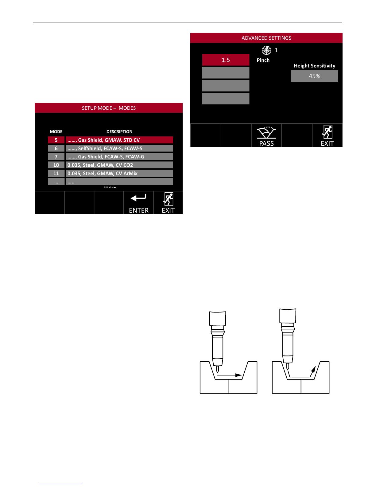
List Mode Select
Lincoln Electric power supplies come with pre-set
welding modes for particular welding applications and
wire types. Press the Modes selection button on the
Manual Mode Selection Screen to see a list of weld
modes loaded into the power supply.
Press the Modes selection button – see FIGURE 21 -
List Mode Screen – below.
FIGURE 21 - List Mode Screen
The available weld modes are displayed in sequential
order. The available modes depend on the present
equipment.
Use the left toggle or turn the steering knob to choose
an available weld mode then press the Enter Selection
button.
Advanced Process Setup
Certain weld modes have advanced settings specic
to that mode or process. Pressing the ADV Selection
button on the Process Setup screen will present the
user with the advanced options associated with the
selected weld mode – see FIGURE 22 - Advanced
Settings.
OPERATION
FIGURE 22 - Advanced Settings
Height Sensitivity
Height sensitivity is a global setting available regardless of the weld mode selected. The operator can
program the system to react to changes following the
prole of the joint.
Higher sensitivity will result in faster adjustment which
could cause hesitation in torch height and abrupt
changes in the weld as shown in FIGURES A and B.
Maintaining a low height sensitivity allows for higher
quality and more consistent welds. This includes ad-
justing for out-of-round pipes, maintaining heat input
and helping with puddle control on the joint prole. It
is recommended that the operator start the weld at a
lower sensitivity setting for the best performance. This
will also assist in avoiding an over reaction to changes
in the structure of the materials being welded.
Advanced Options
Available options are based on the selected weld
mode.See the Power Wave settings for a full breakdown and explanation of advanced options.
Wave Controls
Some typical wave controls are:
• Pinch
• Hot Start
• UltimArc
®
FIGURE A - JOINT
Low Sensitivity < 50
B-19
FIGURE B - JOINT
High Sensitivity > 50
Page 31

APEX® 3 SERIES MIG PENDANT MANUAL
OPERATION
Start Settings
The Start Settings should be set up after the process
setup has been completed. The start settings screen –
see FIGURE 24 - Start Settings Screen – allows the
user to adjust the start settings specic to the program which affect how the system acts when the weld
starts. The start settings take effect as soon as the
Start/Stop button is pressed to initiate the weld. Refer
to page B-21 to see a full timing diagram.
FIGURE 23- Setup Menu
RunIn WFS
Determines the WFS prior to establishing an arc will
ramp up to welding WFS during upslope.
RunIn Volts
The voltage or trim setting at which the system begins
to weld. Once established, it will ramp to welding voltage during upslope.
Motion Delay
This determines how long the system will wait before
beginning to travel and oscillate.
End Settings
The end settings screen – see FIGURE 25 - End
Settings Screen – allows the user to adjust the end
settings specic to the program, which affect how the
system will behave at the end of the weld. End settings take effect as soon as the Start / Stop button is
pressed to stop the weld. (Refer to page B-21 to see
a full GMAW/FCAW timing diagram.) The settings that
can be changed in this screen are:
Crater WFS - The wire feed speed during crater
Crater Volts/Trim - The amount of voltage/trim during
crater
Crater Time - The duration of crater
Burnback - The time the arc is maintained after the
wire stops at the end of a crater.
Downslope - The time to ramp from welding parameters to crater parameters
Postow - How long the gas continues to ow after
the weld to provide shielding
Both the Start and End Settings screens provide access to the Advanced screen to allow advanced values
to be set for start and end of weld.
FIGURE 24 - Start Settings Screen
The settings that can be changed in this screen are:
Preow
The amount of time (sec) that gas ows before welding
begins to ensure adequate gas coverage for the weld
preventing starting porosity.
Upslope
This is the amount of time (sec) it takes for the system
to ramp up from start settings to welding parameters.
FIGURE 25 - End Settings Screen
B-20
Page 32

APEX® 3 SERIES MIG PENDANT MANUAL
OPERATION
B-21
Left
Right
Center
Page 33

APEX® 3 SERIES MIG PENDANT MANUAL
OPERATION
Service Menu
The Service Screen allows for advanced welding options.
There are ve menus available in the Service Screen:
Version, Motion, Faults, Settings and Input Tests.
FIGURE 27 - Service Options Page
Version
The version option of the service menu shows the user
information about the installed software and hardware.
Paging through the screens can be done using the Next
Selection button and the Previous Selection button – see
FIGURE 27 - Service Screen Versions
FIGURE 27 - Service Screen Versions
Motion
Motion controls allows the user to select certain motions and behaviors of the weld system – see FIGURE
28 - Motion Controls Screen – for available options.
FIGURE 28 - Motion Controls Screen
Service Motion items are:
Steering Increment - Changes the distance the oscillation axis will move for each click of the steering knob.
Head Orientation - Rotating the orientation of the
torch relative to the weld head requires changing the
system settings and physically inverting the weld head.
The setting must match the physical orientation.
Torch Retract Distance - Changes how far the torch
retracts at the end of the weld. This allows for greater clearance, enabling a return home to trim the wire
before restarting.
WFS Test - The APEX system performs all calibrations
internally. However, in order to comply with welding
standards, the system allows for verication. The WFS
Test will produce a desired amount of wire for a preset
length of time for verication.
Travel Test - The APEX system does all calibrations
internally. However, in order to comply with welding
standards, the system allows for verication. Travel
Test will travel for the specied distance for verication.
The distance must be measured on the track
ring gear or on a at track.
B-22
Page 34

APEX® 3 SERIES MIG PENDANT MANUAL
OPERATION
FIGURE 29 - Faults Screen On Settings
Faults
While welding, the ow of shielding gas and/or cooling
water can be monitored if the appropriate hardware is
present. For gas ow, the required level can be specied. The Faults Screen On Settings shown in
FIGURE 29 provides access to these features.
Water ow is detected by an ArcLink® connected
CoolArc™ 55S.
FIGURE 31 - Settings Screen
Use the Left Toggle to select GAS or WATER and then
the Right Toggle to turn monitoring ON/OFF. With gas
monitoring turned ON, two additional controls are
made available; a LEVEL selection to input the required
level of gas ow using the Right Toggle and a REF value which will display the current gas ow value when
the PURGE button is pushed.
If the Gas Fault is turned ON, gas ow level will be
monitored during welding and compared to the required ow level. If the monitored ow level is less than
the required level, the weld will be terminated and a
message will be displayed indicating a Gas Fault.
With the Water Fault turned ON, water ow will be
monitored during welding. If it’s determined that water
is not owing, the weld will be terminated and a message will be displayed indicating a Water Fault.
If the Gas and Water faults are turned OFF, welding will
continue regardless of the level of Gas or Water ow. If
the appropriate ow sensor hardware is not present in
the system then the corresponding fault(s) should be
disabled.
FIGURE 30 - Faults Screen Off Settings
Settings
The Settings Menu shown in FIGURE 31- Settings
Screen – provides access to the Production Monitor-
ing feature. When enabled, it will automatically archive
a summary of each weld to an inserted USB drive. Use
the Right Toggle to turn this feature ON/OFF.
Input Test
The Input Test menu shown in FIGURE 32 - Input Test
Screen, page B-24 – provides a Supervisor with the
ability to quickly determine if the pendant input devices
(buttons, switches, and steering knob) are working
correctly.
B-23
Page 35

APEX® 3 SERIES MIG PENDANT MANUAL
OPERATION
FIGURE 32 - Input Test Screen
Note: Pushing the Reset Button resets the system.
Once the Input Test screen is displayed, a system test
may be performed. Each button and toggle switch on
the Pendant will turn green when pushed up, down or
released.
Turning the steering knob clockwise should turn the
right portion of the knob green indicating the direction of the rotation. Turning the steering knob counter-clockwise should turn the left portion of the kno
green indicating the direction of the rotation.
Pushing and releasing the steering knob button should
turn the center of the knob green and produce a corresponding message. After operating all Pendant input
devices, the representations of the devices on the
screen should be highlighted in green. Any that are not
highlighted are not working correctly.
Return to the Service Options page by pushing the
steering knob and sector button at the same time.
How To Take A Snapshot
If a USB drive is inserted into the APEX 30M controller,
APEX 30S controller or APEX 3000 controller, the Pendant will allow a snapshot to be taken from the screen
shown in FIGURE 33 - Snapshot Service Mode..
Snapshots can also be taken from the screen shown in
FIGURE 34 - Snapshot System Fault.
A Snapshot provides detailed information concerning
the systems current conguration and status and is
initiated by pushing the SNAP Selection button.
The snapshot process may take several minutes to
complete during which time a status screen like the
one shown in FIGURE 35 - Snapshot Status Screen
is presented.
FIGURE 33 - Snapshot Service Mode
FIGURE 34 - Snapshot System Fault
FIGURE 35 - Snapshot Status Screen
B-24
Page 36
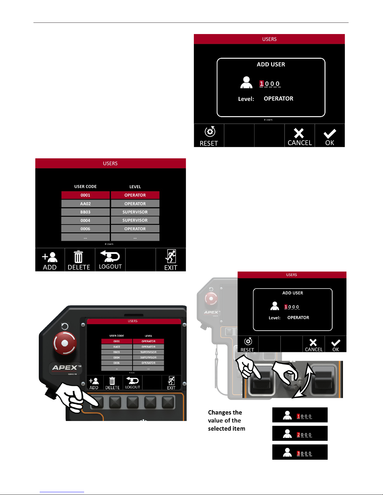
APEX® 3 SERIES MIG PENDANT MANUAL
Users
The Users Screen – see FIGURE 36 - Users Screen –
allows the user to set up operator and supervisor log in
codes. Each user can be assigned an individual code
which determines the level of access.
Fast Movement
Using the steering knob, Fast Movement is enabled on
this screen. In addition, use the steering knob or the
left and right toggles for navigation and selection.
Adding Users
Only those with supervisor access are able to view the
users screen.
OPERATION
FIGURE 37 - Add User
As demonstrated in the example above, pressing the
Add Selection button will bring up the Add User screen
– see FIGURE 37 - Add User.
Once the code has been selected, the supervisor can
determine the user’s level of access.
FIGURE 36 - Users Screen
Press the Add User Selection button.
Operator - The operator has no access to the settings
and will only be able to operate within the parameters
placed by the supervisor for each program.
Supervisor - The supervisor has full rights and access
to all weldings parameters and setup screens.
B-25
Page 37
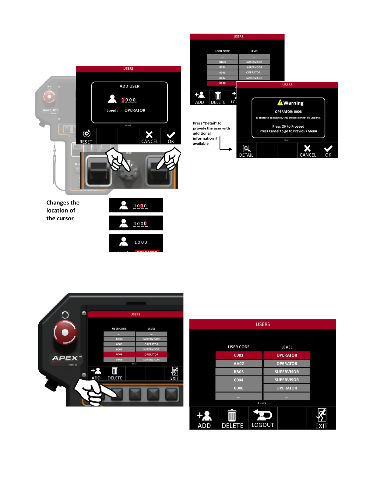
APEX® 3 SERIES MIG PENDANT MANUAL
Once you have chosen the appropriate User code
and level of access, select OK. Reset will change
characters back to “0000”.
OPERATION
Deleting a user account will bring up a warning
screen. Press the Detail Selection button to see more
information about the shown screen.
Deleting Users
Press the Delete Selection Button after selecting a user
from the list.
CAUTION: DELETING ALL SUPERVISORS WILL
REQUIRE A FACTORY RESET. PLEASE CONTACT
THE FACTORY FOR INSTRUCTIONS.
The warning screen allows the user the chance to
review what is being deleted. It also shows the level
of access and the user code. The example on page
B-27 shows OPERATOR:0008. If this User Code
had supervisory access the screen would read:
SUPERVISOR:0008.
If there are too many users to t on the screen, the last
box will contain ellipses – see FIGURE 38 - Multiple
Users. This indicates that there are additional system
users and the table will scroll to access each one.
bottom of the elds it will tell how many user codes are
currently listed in the system.
At the
FIGURE 38 - Multiple Users
B-26
Page 38
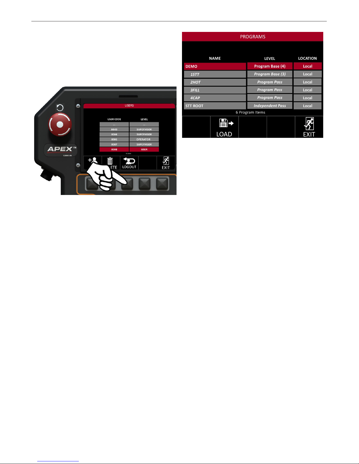
APEX® 3 SERIES MIG PENDANT MANUAL
Changing User Access
To change the level of access that a user has been
granted press the ADD selection button. Instead
of entering a unique user code add in the existing
user code that needs to be changed. With “Level”
highlighted, choose the new access level.
OPERATION
FIGURE 39 - Operator Log In
Since operators cannot save, delete, or create programs, they are presented with the program options
available to them. They can select only these programs.
When entering setup mode, operators are
automatically brought to the Programs Screen.
Log Out
To change users, press the Logout Selection button.
This logs out the current user so that a new user can
log in.
Note: If the new user code is set as an operator they
will not have full access to the system settings. Be sure
to always have at least one supervisor code at all times
for full system access.
Operator Log In
When an operator logs into the pendant they are
presented with the program screen – see FIGURE 39 -
Operator Log In.
B-27
Page 39

APEX® 3 SERIES MIG PENDANT MANUAL
OPERATION
Increments Settings
The increments screen – see FIGURE 40 - Increments
Screen – is used to set how much a single button
press will change each value and limit the operator’s
access to certain parameters.
The system minimum and maximum values provided
to the user are based on the welding power source,
weld mode, wire diameter and other factors.
The increment options that can be set are:
• Wire Feed Speed
• Amperage
• Voltage or Trim (depending on Weld Mode)
• Travel Speed
• Oscillation Width
• Oscillation Speed
• Dwell Time
Each of these values can have a minimum and
maximum value set that the operator will not be able to
exceed. These increments can be set per program and
per pass.
To reset all increments back to their widest tolerance
press the Reset Selection button.
Operator limitations also include the ability to set the
system units between Imperial to Metric, which can
only be performed by a supervisor.
If a multipass program is loaded, pressing the sector
button (button number 14 shown below) will advance
to the next pass. This allows the user to quickly set the
limits and increments for each pass.
FIGURE 40 - Increments Screen
Refer to page B-29 for a complete list of increment
values for both imperial and metric measurements.
B-28
Page 40

APEX® 3 SERIES MIG PENDANT MANUAL
OPERATION
SETUP SCREEN
VALUE NAME
IMPERIAL
INCREMENTS
INCREMENTS
INCREMENTS & LIMITS MENU
Wire Speed ipm cm/min
Voltage Volts Volts
Amperage Amps Amps
Travel Speed ipm cm/min
Oscillation Width inches centimeters
Oscillation Speed ipm cm/min
Oscillation Dwell seconds seconds
START SETTINGS MENU
Preow seconds seconds
Upslope seconds seconds
Runin Wire Feed Speed ipm cm/min
Runin Voltage Volts Volts
Motion Delay seconds seconds
METRIC
END SETTINGS MENU
Crater Wire Feed Speed ipm cm/min
Crater Voltage Volts Volts
Crater Time seconds seconds
Burnback seconds seconds
Downslope seconds seconds
Postow seconds seconds
PROCESS SETUP MENU
Wire Feed Speed ipm cm/in
Voltage Volts Volts
Amperage Amps Amps
Travel Speed ipm cm/min
Oscillation Width inches centimeters
Oscillation Speed ipm cm/min
Left Dwell seconds seconds
Right Dwell seconds seconds
B-29
Page 41

APEX® 3 SERIES MIG PENDANT MANUAL
Programs
From the program screen – see FIGURE 41-
Programs Screen – programs can be saved into the
system or onto a USB memory stick.
Fast Movement
Fast movement using the steering knob is enabled
on this screen. Use the steering knob or left and right
toggles for navigation and selection.
OPERATION
FIGURE 41 - Programs Screen
Saving an Independent Pass
A supervisor can change the parameters of the loaded
program. Once the parameters are changed, they can be
saved as a new program.
Pressing the save selection button will take the user to
a sub-menu. This menu will allow the user to program
the following variables:
Location: Selects where the program is saved
• Local: This saves directly to the Pendant
• USB: This saves to the installed USB. This option only
appears when a USB is plugged in.
Level: Selects what type of Program is being saved
• Independent Pass - stand alone weld procedures, not
tied to any other program
• Program Base - The rst step in creating multiple
passes which tie together to form a full welding
procedure; this is explained in the next section.
• Program Pass - These are tied to the Program Base
and can be created as needed by the user. For example
a pipe could require four passes, so each pass could be
saved under a Program Base for easy retrieval
Pass Name: Allows the user to select a unique pass
name to identify the pass or program.
Once the location and level are set, a unique name is
given to the program. This name should be distinct to
prevent confusion.
B-30
Page 42
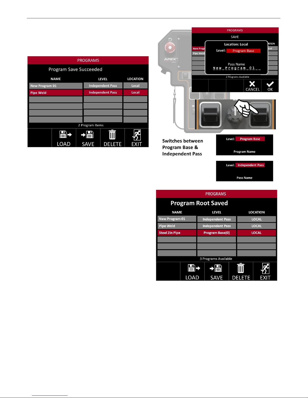
APEX® 3 SERIES MIG PENDANT MANUAL
Note: Saving to a USB limits the program to 8 characters.
The name eld always auto populates with the name
for the currently loaded program or the program name
selected when the save button was pushed.
Saving a Program Base
If there are multiple passes within the same procedure,
setting up a Program Base is recommended.
OPERATION
In the save program sub-menu, change the level from
Independent Pass to Program Base.
Saving a Program Pass
Once a program base is saved, the next step is to
create individual passes within the Program Base
for the settings to be saved.
B-31
Page 43

APEX® 3 SERIES MIG PENDANT MANUAL
OPERATION
Saving Program Updates
A fourth level selection, Program Update is available
when changes are made to Program Passes associated with a Program Base.
When changes have been made to one or more
Program Passes, the Program Base containing the
changed Program Passes is selected and the SAVE
button is pressed, the Program Update option
becomes available on the SAVE screen.
If changes were made to one or all of the Program
Passes associated with the Program Base “Steel 2in
Pipe”, selecting the Program Base and pressing the
SAVE button would product the following screen:
For this example the pass has been named 1Root.
Continue to save programs to this base until the
required passes are all saved.
After saving the required passes they are all displayed
under the base – see FIGURE 42 – Full Program Base.
Pressing the steering knob will expand the program
base.
FIGURE 42 - Full Program Base
Selecting Program Update and pressing the OK button on this screen will save the changes made to all
Program Passes at one time rather than requiring each
Program Pass to be saved separately.
B-32
Page 44
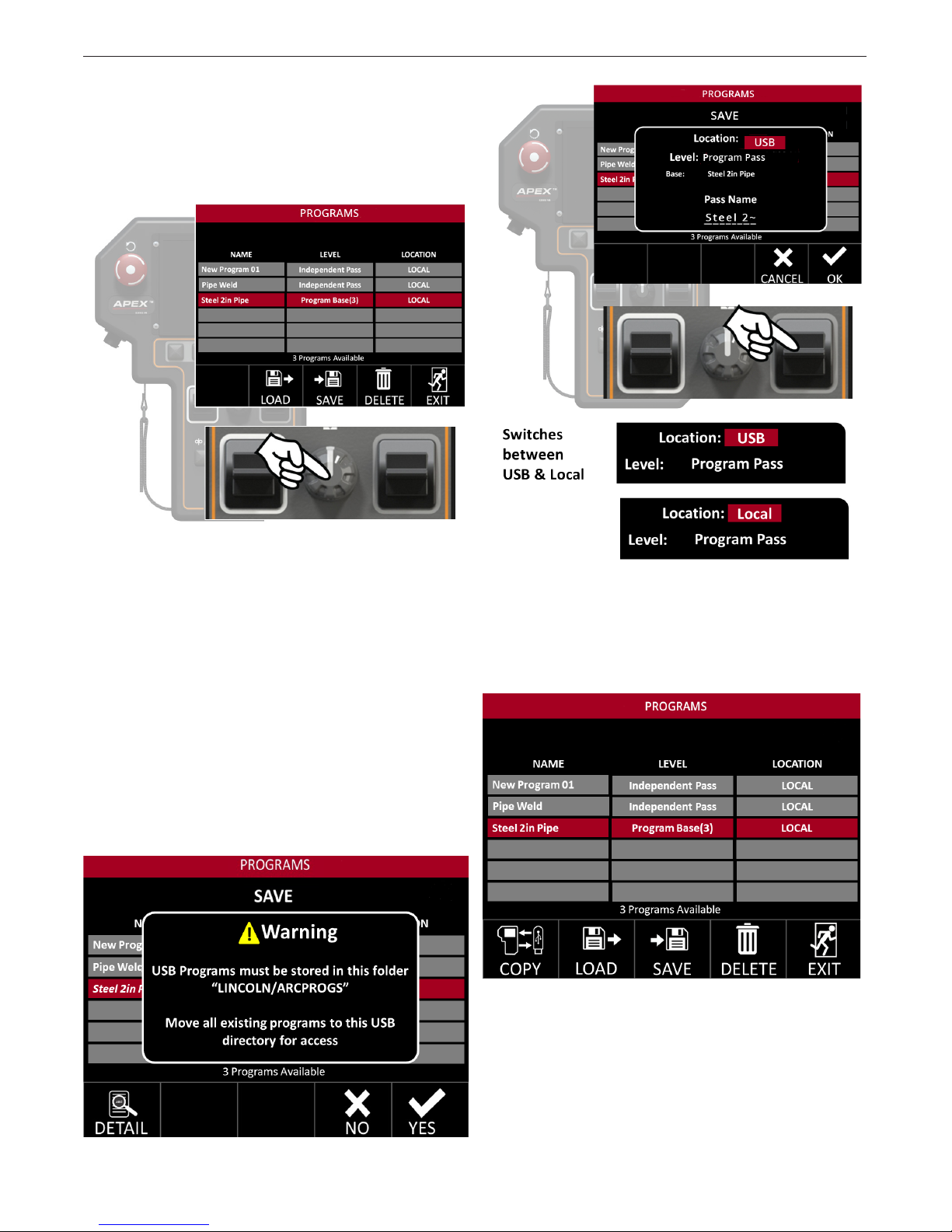
APEX® 3 SERIES MIG PENDANT MANUAL
Hide Program Passes
The passes in a program base can be hidden by
highlighting the program base and pressing the
steering knob, collapsing the group. Press the steering
knob again and it will expand.
OPERATION
Saving to a USB
All of the examples shown have been saved locally to
the pendant. They can also be saved to a USB.
The USB has a folder set up specially to save or
read les. If this folder is missing then a prompt will
appear on the screen – see FIGURE 43 - USB Folder
Notication. If the ash drive is new, the system will
create a folder.
To access les already saved on the USB, move them
to the specied directory.
Note: A USB le name is restricted to 8 characters.
Local les can be up to 16 characters. The only
program name blocked is “Lincoln”.
Copy to/from USB
With the USB inserted, a Copy Icon appears in the
bottom left of the screen - see FIGURE 44 - Copy
Icon.
FIGURE 44 - Copy Icon
FIGURE 43 - USB Folder Notication
Press the Copy Selection Button.
A copy of the selected program is made – see FIGURE
45 – Copy to USB
If the le is currently saved on the USB, it will save to
the Pendant, if it is a Local le (saved to the pendant),
it will save to USB.
B-33
Page 45
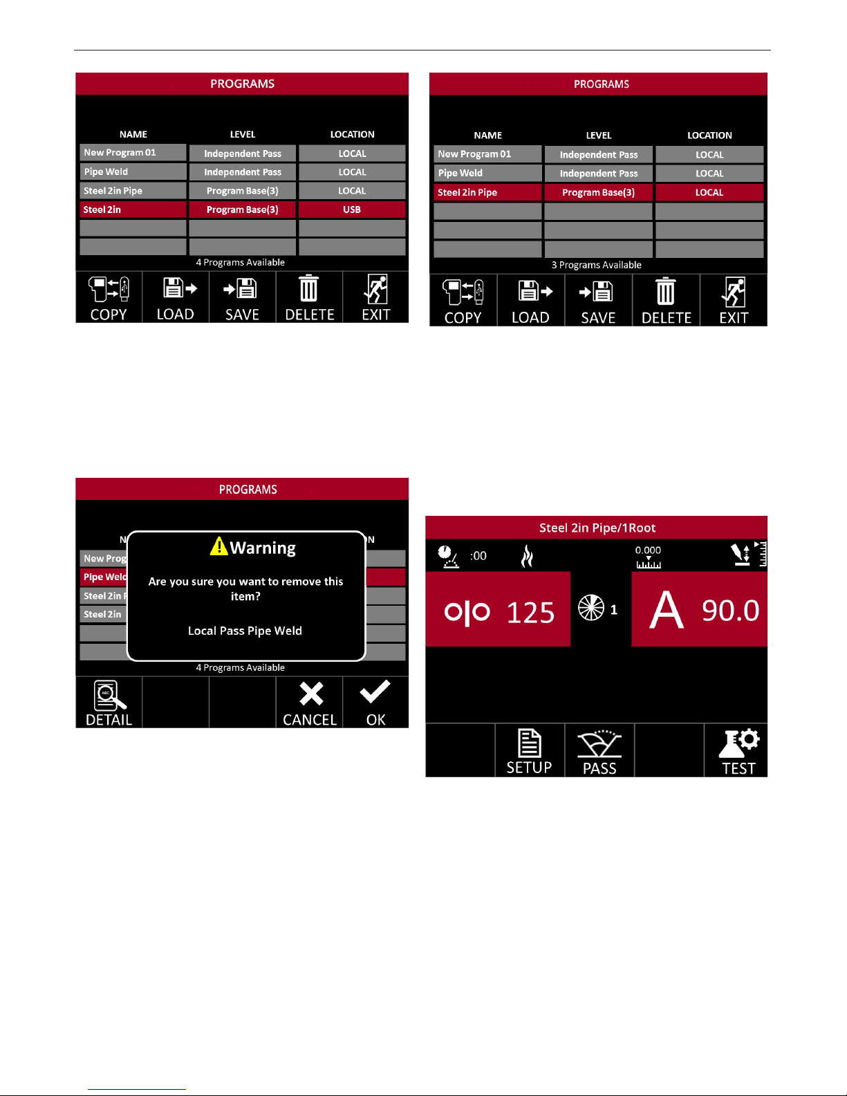
APEX® 3 SERIES MIG PENDANT MANUAL
OPERATION
FIGURE 45 - Copy to USB
Note: If a locally saved program has more than 8
characters, copying to a USB will truncate it to the
rst 7 characters of the original name and a tilde (~)
to indicate that it’s shortened. To save with a unique
name, load the program and then manually save to
the USB with the desired 8-character name.
FIGURE 47 - Loading Program
Go to the Programs Menu to load the relevant
program. Highlight the program or base.
Press the Load Selection button. This will load the applicable program. See FIGURE 47 Loading Program
and FIGURE 48 - Loaded Program.
FIGURE 46 - Program Delete
Deleting a Program
Saved programs can be deleted by highlighting the
program and pressing the Delete Selection button.
This will bring up a new window – see FIGURE 46-
Program Delete.
Press the Delete Selection Button.
Deleting a Program Base
If a Program Base is deleted then all associated passes are also deleted.
Loading a Program
FIGURE 48 - Loaded Program
B-34
Page 46
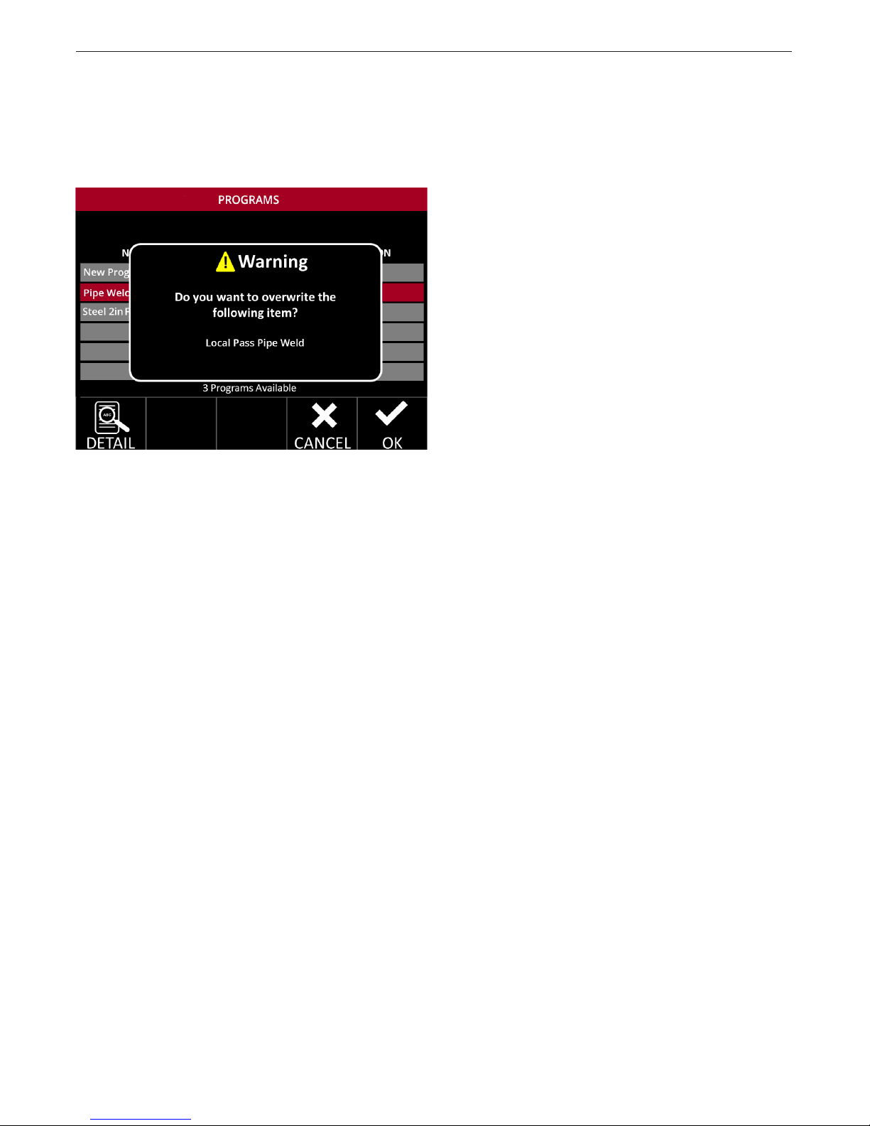
APEX® 3 SERIES MIG PENDANT MANUAL
Overwriting a Program
Saving a le with the same name will overwrite the
existing program. The system gives a warning that the
existing program will be overwritten. Overwriting will
delete the original program.
OPERATION
B-35
Page 47
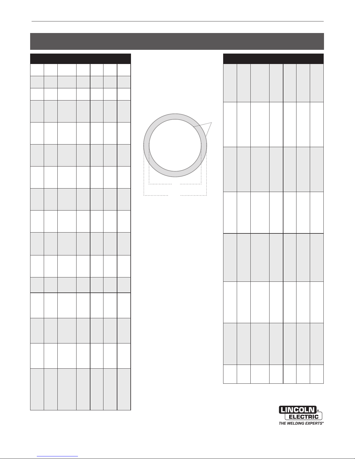
APEX® 3 SERIES MIG PENDANT MANUAL
STANDARD PIPING SCHEDULE CHART
ODinOD
1/8
0.405
1/4
0.54
3/8
0.675
1/2
0.84
3/4
1.05
1
1.315
1¼
1.66
1½
1.9
2
2.375
2½
2.875
3
3.5
3 ½
4
4
4.5
5
5.563
6
6.625
8
8.625
mm
10.3
13.7
1 7.1
21.3
26.7
33.4
42.2
48.3
60.3
73
88.9
101.6
114.3
141.3
168.3
21 9.1
Schedule
10S
40ST, 40S
80SX, 80S
10S
40ST, 40S
80SX, 80S
10S
40ST, 40S
80SX, 80S
5S
10S
40ST, 40S
80SX, 80S
5S
10S
40ST, 40S
80SX, 80S
160
XX
5S
10S
40ST, 40S
80SX, 80S
160
XX
5S
10S
40ST, 40S
80SX, 80S
160
XX
5S
10S
40ST, 40S
80SX, 80S
160
XX
5S
10S
40ST, 40S
80SX, 80S
160
XX
5S
10S
40ST, 40S
80SX, 80S
160
XX
5S
10S
40ST, 40S
80SX, 80S
160
XX
5S
10S
40ST, 40S
80SX, 80S
5S
10S
40ST, 40S
80SX, 80S
120
160
XX
5S
10S
40ST, 40S
80SX, 80S
120
160
XX
5S
10S
40ST, 40S
80SX, 80S
120
160
XX
5S
10S
20
30
40ST, 40S
60
80SX, 80S
100
120
140
XX
160
WallinWallmmIDinID
0.049
1.24
1.73
2.41
1.65
2.24
3.02
1.65
2.31
3.2
1.65
2.1 1
2.77
3.73
4.78
7. 4 7
1.65
2.1 1
2.87
3.91
5.56
7. 8 2
1.65
2.77
3.38
43.355
6.35
9.09
1.65
2.77
3.56
4.85
6.35
9.7
1.65
2.77
3.68
5.08
7.1 4
10.16
1.65
2.77
3.91
5.54
8.74
11.07
2.1 1
3.05
5.1 6
7. 01
9.53
14.02
2.1 1
3.05
5.49
7. 62
11.13
15.24
2.1 1
3.05
5.74
8.08
2.1 1
3.05
6.02
8.56
11.13
13.49
1 7.1 2
2.77
3.4
6.55
9.53
12.7
15.88
19.05
2.77
3.4
7.1 1
10.97
14.27
18.26
21.95
2.77
3.76
6.35
7. 04
8.1 8
10.31
12.7
15.09
18.26
20.62
22.23
23.01
0.307
0.269
0.21 5
0.41
0.364
0.302
0.54 5
0.493
0.42 3
0.71
0.674
0.622
0.546
0.464
0.252
0.92
0.884
0.824
0.74 2
0.612
0.43 4
1.185
1.097
1.049
0.957
0.815
0.599
1.53
1.442
1.38
1.278
1.16
0.896
1.77
1.682
1.61
1.5
1.338
1.1
2.245
2.1 57
2.067
1.939
1.687
1.503
2.709
2.635
2.469
2.323
2.1 25
1.771
3.334
3.26
3.068
2.9
2.624
2.3
3.93 4
3.76
3.548
3.364
4.334
4.26
4.026
3.826
3.624
3.438
3.152
5.345
5.295
5.047
4.813
4.563
4.313
4.063
6.407
6.357
6.065
5.761
5.501
5.187
4.897
8.407
8.329
8.1 25
8.071
7.981
7.813
7. 62 5
7. 4 3 7
7.187
7.001
6.875
6.813
0.068
0.095
0.065
0.088
0.119
0.065
0.091
0.1 26
0.065
0.083
0.109
0.1 47
0.1 88
0.294
0.065
0.083
0.113
0.1 54
0.21 9
0.308
0.065
0.109
0.1 33
0.1 79
0.25
0.358
0.065
0.109
0.1 4
0.191
0.25
0.382
0.065
0.109
0.1 45
0.2
0.281
0.4
0.065
0.109
0.1 54
0.21 8
0.34 4
0.436
0.083
0.1 2
0.203
0.276
0.375
0.552
0.083
0.1 2
0.21 6
0.3
0.438
0.6
0.083
0.1 2
0.22 6
0.318
0.083
0.1 2
0.23 7
0.337
0.438
0.531
0.674
0.109
0.1 34
0.25 8
0.375
0.5
0.625
0.75
0.109
0.1 34
0.28
0.43 2
0.562
0.719
0.864
0.109
0.1 48
0.25
0.27 7
0.322
0.406
0.5
0.594
0.719
0.812
0.875
0.906
mm
7. 8
6.83
5.46
10.41
9.25
7. 67
13.84
12.52
10.74
18.03
1 7.1 2
15.8
13.87
11.79
6.4
23.37
22.45
20.93
18.85
15.54
11.02
30 .1
2 7. 86
26.64
24.31
20.7
15.21
38.86
36.63
35.05
32.46
29.46
22.76
44.96
42.7 2
40.89
38 .1
33.9 9
2 7. 84
5 7.0 2
54.79
52.5
49.2 5
42.85
38.18
68.81
66.93
62.71
59
53.98
44.98
84.68
82.8
7 7.9 3
73.66
66.65
58.42
97.38
95.5
90 .12
85.45
110.1
108.2
102.3
9 7. 2
92
87.3
80 .1
135.8
134.5
128.2
122.3
115.9
109.6
103.2
162.7
161.5
154.1
146.3
139.7
136.7
124.4
213.5
211.6
206.4
205
202.7
198.5
193.7
188 .9
182.5
177.8
174.6
17 3.1
LEGEND
Wall: Thickness of Material
OD: Outside Diameter
ID: Inside Diameter
WALL
ID
OD
ODinOD
10
10.75
12
12.75
14
14
16
16
18
18
20
20
24
24
30
30
mm
273
323.8
355.6
406.4
457
508
610
762
Schedule
5S
10S
20
30
40ST, 40S
60XS, 80S
80
100
120
140, XX
160
5S
10S
20
30
ST, 40S
40
S,80S
60
80
100
120,XX
140
160
5S
10S
10
20
30,ST
40
XS
60
80
100
120
140
160
5S
10S
10
20
30,ST
40, XS
60
80
100
120
140
160
5S
10S10
20
ST
30
XS
40
60
80
100
120
140
160
5S
10S
10
20,ST
30, XS
40
60
80
100
120
140
160
5S
10, 10S
20, ST
XS
30
40
60
80
100
120
140
160
5S
10, 10S
ST
20, XS
30
WallinWallmmIDinID
0.1 34
3.4
4.19
6.35
7. 8
9.27
12.7
15.09
18.26
21.44
25.4
28.58
3.96
4.587
6.35
8.38
9.53
10.31
12.7
14.27
1 7. 4 8
21.44
25.4
28.58
33.32
3.96
4.78
6.35
7.9 2
9.53
11.13
12.7
15.09
19.05
23.83
2 7. 79
31.75
35.71
4.19
4.78
6.35
7.9 2
9.53
12.7
16.66
21.44
26 .19
30.96
36.53
40.49
4.19
7. 78
6.35
7.9 2
9.53
11.13
12.7
14.27
19.05
23.83
29.36
34.93
39.67
45.24
4.78
5.54
6.35
9.53
12.7
15.09
20.62
26 .19
32.54
38 .1
44.45
50.01
5.54
6.35
9.53
12.7
14.27
1 7. 4 8
24.61
30.96
38.89
46.02
52.37
59.54
6.35
7.9 2
9.53
12.7
15.88
10.48 2
10.42
10.25
10.136
10.02
9.75
9.562
9.312
9.062
8375
8.5
12.438
12.39
12.25
12.09
12
11.938
11.75
11.626
11.374
11.062
10.75
10.5
10 .126
13.688
13.624
13.5
13.376
13.25
13.124
13
12.812
12.5
12.124
11.812
11.5
11.188
15.67
15.624
15.5
15.376
15.25
15
14.688
14.312
13.938
13.562
13.124
12.812
1 7. 67
1 7. 62 4
1 7. 5
17.376
1 7. 2 5
1 7.1 2 4
17
16.876
16.5
16.124
15.688
15.25
14.876
14.438
19.624
19.564
19.5
19.25
19
18.812
18.376
17.938
1 7. 4 38
17
16.5
16.062
23.564
23.5
23.2 5
23
22.876
22.62 4
22.06 2
21.562
20.938
20.376
19.876
19.312
29.5
29.376
29.25
29
28.75
0.165
0.25
0.307
0.365
0.5
0.594
0.719
0.84 4
1
1.1 2
0.156
0.1 8
0.25
0.33
0.375
0.406
0.5
0.562
0.688
0.84 4
1
1.125
1.312
0.156
0.1 88
0.25
0.312
0.375
0.438
0.5
0.594
0.75
0.938
1.094
1.25
1.406
0.165
0.1 88
0.25
0.312
0.375
0.5
0.656
0.84 4
1.031
1.219
1.438
1.594
0.165
0.1 88
0.25
0.312
0.375
0.438
0.5
0.562
0.75
0.938
1.156
1.375
1.562
1.781
0.1 88
0.21 8
0.25
0.375
0.5
0.594
0.812
1.031
1.281
1.5
1.75
1.969
0.21 8
0.25
0.375
0.5
0.562
0.688
0.969
1.218
1.531
1.812
2.062
2.344
0.25
0.312
0.375
0.5
0.625
266.2
264.7
260.4
2 5 7.5
254.5
2 4 7.7
24 2.9
236.5
230. 2
222.3
215 .9
315.9
314.7
311.2
307.1
304.8
304.2
298.5
295.3
288 .9
281
27 3.1
266.7
2 5 7. 2
3 4 7. 7
346
34 2.9
339.8
336.6
333.3
330.2
325.4
3 1 7.5
308
300
29 2.1
284.2
398
396.8
393.7
390.6
387.4
381
37 3.1
363.5
354
344.5
333.3
325.4
449
448
445
441
438
435
432
429
419
410
398
387
378
367
498
497
495
489
483
478
467
456
443
432
419
408
599
597
591
584
581
575
560
548
532
518
505
491
749
746
743
737
730
mm
36
Page 48
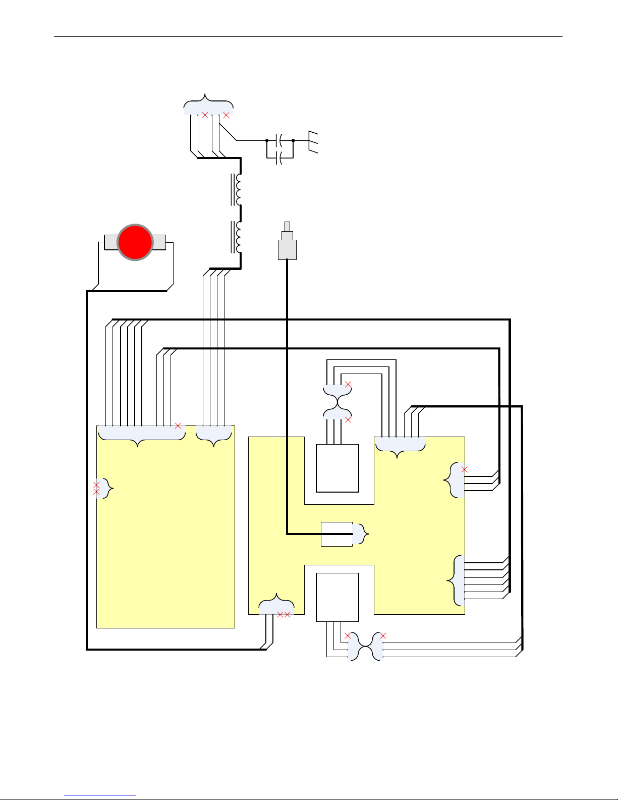
APEX® 3 SERIES MIG PENDANT MANUAL
.01 IN. (
0.25MM)
.005 IN. (
0.127MM)
APPROVED:
PAGE
SUBJECT:
EQUIPMENT TYPE:
DOCUMENT
REVISION:
DOCUMENT
NUMBER:
REFERENCE:
PROJECT
NUMBER:
MATERIAL
DISPOSITION:
UNITS:
SCALE:
ARC
PRODUCTS
DRAWN BY:
ENGINEER:
CONTROL:
THIS DOCUMENT CONTAINS PROPRIETARY INFORMATION OWNED BY LINCOLN GLOBAL, INC. AND MAY NOT BE DUPLICATED, COMMUNICATED
TO OTHER PARTIES OR USED FOR ANY PURPOSE WITHOUT THE EXPRESS WRITTEN PERMISSION OF LINCOLN GLOBAL, INC.
A
INCH
J. SNEAD
6/1/18
APPROVAL
DAT E:
1
OF
1
S32569
PENDANT WIRING DIAGRAM
J. SNEAD
SC
S30454
PENDANT
IF PRINTED
@ B SIZE (11"X17")
CRA0751
ABCDF
DIAGRAMS
E
PANEL MOUNT
RECEPTACLE
811B
812B
814B
813B
.0047uF
L2
RESET PUSHBUTTON
1
3011
2
3012
L1
.0047uF
PANEL MOUNT
ENCODER
321
301
2
1
RECEPTACLE
303
307
308
309
3010
3005
3003
302
1
3
CON5
789
CON3
542
10
811B
812B
813B
814B
123
6
4
CON2
PLUG
321
BLU
TOP
RED
CENTER
BLK
BOTTOM
4
4
USER
3094
3095
3096
3093
3092
3091
321
456
J4
LEFT SWITCH
4
302
3
J1
3003
2
3005
1
G8569-1
PENDANT UI
J6
J5
1
4
2
3
3011
3012
USER
BOTTOM
TOP
CENTER
RIGHT SWITCH
BLK
BLU
RED
4
1
2
3
PLUG
4
1
2
3
RECEPTACLE
3093
3092
3091
PENDANT I/O
G8571-1
3010
6
309
5
308
4
J3
3
2
1
307
303
301
NOTE: This diagram is for reference only. It may not be accurate for all machines covered by this manual. The specific diagram for a particular code is pasted inside
the machine on one of the enclosure panels. If the diagram is illegible, write to the Service Department for a replacement. Give the equipment code number.
37
Page 49

APEX® 3 SERIES MIG PENDANT MANUAL
PARTS
APEX ® 3 SERIES MIG PENDANT PARTS
This parts list is provided as an informative guide only.
38
Page 50

APEX® 3 SERIES MIG PENDANT MANUAL
GENERAL ASSEMBLY
PARTS
APEX® 3 Series MIG Pendant
For Code: 12879
Do not use this Parts List for a machine if its code number is not listed. Contact the Service Department for any
code numbers not listed.
Use the illustration of Sub-Assemblies page and the table below to determine which sub assembly page and
column the desired part is located on for your particular code machine.
Sub Assembly
Item Number
SUB ASSEMBLY
PAGE NAME
PAGE NO.
CODE NO.
12879 1
1 2 3 4 5 6 7
APEX 3 Series Pendant
40
2
NOTE: This Parts Manual is provided as an informative guide only. When ordering parts always refer to the
Lincoln Electric Parts List.
02-07-19
39
Page 51

40
Page 52

APEX® 3 SERIES PENDANT MANUAL
PARTS
NOTE: This Parts Manual is provided as an informative guide only. When ordering parts always refer to the
Lincoln Electric Parts List.
41
Page 53

APEX® 3 SERIES MIG PENDANT MANUAL
PARTS
# Indicates a change in this printing.
Use only the parts marked “x” in the column under the
heading number called for in the model index page.
ITEM DESCRIPTION PART NO. QTY 1 2
1
1A
1B
Rocker Switch & Harness Assembly, includes:
Rocker Switch
Harness Assembly
9SS30720
9SS30493
NSS
2
2
2
X
X
X
2 Color LCD 9SS29390 1 X X
3 Pendant Top 9SM23062-2 1 X X
4 Pendant Overlay 9SS30292 1 X X
5 Screen Holder 9SM24594 1 X X
6 Screen Protector 9SS30712 2 X X
7 Pendant Bottom (Includes item 12) 9SM23063 1 X X
8 UI to IO Link Harness 9SS30398 1 X X
9 Pendant Estop Harness 9SS30399 1 X X
10 Dual Rocker Switch PCB Harness 9SS30717 1 X X
11 Pendant Rocker Switch Harness 9SS30720 2 X X
12
12A
12B
Pendant Input Harness Assembly, includes:
Pendant Input Harness
Screw
9SS30458
NSS
NSS
1
1
4
X
X
X
X
X
X
X
X
X
13
13
13A
13B
14
14
14A
14B
15
15A
15B
15C
16
16A
16B
I/O PCB Assembly, includes:
I/O PCB Assembly, includes:
I/O PCB
Screw
User Interface PCB Assembly, includes:
User Interface PCB Assembly, includes:
User Interface PCB
Screw
Pendant Hook Assembly, includes:
Pendant Hook
Rubber Bumper
Screw
Pendant Strap Assembly, includes:
Pendant Strap A
Pendant Strap B
9SS30302
9SS31339
NSS
NSS
9SS30300
9SS32531
NSS
NSS
9SS29560-22
NSS
NSS
NSS
9SS29560-21
NSS
NSS
1
1
1
4
1
1
1
7
1
1
1
3
1
1
1
X
•
X
X
X
•
X
X
X
X
X
X
X
X
X
17 Emergency Stop Pushbutton 9SS29987 1 X X
19 Button Cover Small 9SS23055-1 11 X X
20 Knob 9SM22778-1 1 X X
21
21A
21B
Spatter Shield Pocket Assembly, includes:
Spatter Shield Pocket
Screws
9SM23325
NSS
NSS
1
1
4
X
X
X
22 Optical Encoder 9SS32527 1 • X
•
X
X
X
•
X
X
X
X
X
X
X
X
X
X
X
X
X
NOTE: This Parts Manual is provided as an informative guide only. When ordering parts always refer to the
Lincoln Electric Parts List.
42
Page 54

CUSTOMER ASSISTANCE POLICY
The business of The Lincoln Electric Company is manufacturing and
selling high quality welding equipment, consumables, and cutting
equipment. Our challenge is to meet the needs of our customers
and to exceed their expectations. On occasion, purchasers may
ask Lincoln Electric for advice or information about their use of our
products. We respond to our customers based on the best information
in our possession at that time. Lincoln Electric is not in a position
to warrant or guarantee such advice, and assumes no liability,
with respect to such information or advice. We expressly disclaim
any warranty of any kind, including any warranty of fitness for any
customer’s particular purpose, with respect to such information or
advice. As a matter of practical consideration, we also cannot assume
any responsibility for updating or correcting any such information or
advice once it has been given, nor does the provision of information or
advice create, expand or alter any warranty with respect to the sale of
our products.
Lincoln Electric is a responsive manufacturer, but the selection and
use of specific products sold by Lincoln Electric is solely within the
control of, and remains the sole responsibility of the customer. Many
variables beyond the control of Lincoln Electric affect the results
obtained in applying these types of fabrication methods and service
requirements.
Subject to Change – This information is accurate to the best of our
knowledge at the time of printing. Please refer to
www.lincolnelectric.com for any updated information.
Page 55

CUSTOMER ASSISTANCE POLICY
The business of The Lincoln Electric Company is manufacturing and
selling high quality welding equipment, consumables, and cutting
equipment. Our challenge is to meet the needs of our customers
and to exceed their expectations. On occasion, purchasers may
ask Lincoln Electric for advice or information about their use of our
products. We respond to our customers based on the best information
in our possession at that time. Lincoln Electric is not in a position
to warrant or guarantee such advice, and assumes no liability,
with respect to such information or advice. We expressly disclaim
any warranty of any kind, including any warranty of fitness for any
customer’s particular purpose, with respect to such information or
advice. As a matter of practical consideration, we also cannot assume
any responsibility for updating or correcting any such information or
advice once it has been given, nor does the provision of information or
advice create, expand or alter any warranty with respect to the sale of
our products.
Lincoln Electric is a responsive manufacturer, but the selection and
use of specific products sold by Lincoln Electric is solely within the
control of, and remains the sole responsibility of the customer. Many
variables beyond the control of Lincoln Electric affect the results
obtained in applying these types of fabrication methods and service
requirements.
Subject to Change – This information is accurate to the best of our
knowledge at the time of printing. Please refer to
www.lincolnelectric.com for any updated information.
Page 56

CUSTOMER ASSISTANCE POLICY
The business of The Lincoln Electric Company is manufacturing and
selling high quality welding equipment, consumables, and cutting
equipment. Our challenge is to meet the needs of our customers
and to exceed their expectations. On occasion, purchasers may
ask Lincoln Electric for advice or information about their use of our
products. We respond to our customers based on the best information
in our possession at that time. Lincoln Electric is not in a position
to warrant or guarantee such advice, and assumes no liability,
with respect to such information or advice. We expressly disclaim
any warranty of any kind, including any warranty of fitness for any
customer’s particular purpose, with respect to such information or
advice. As a matter of practical consideration, we also cannot assume
any responsibility for updating or correcting any such information or
advice once it has been given, nor does the provision of information or
advice create, expand or alter any warranty with respect to the sale of
our products.
Lincoln Electric is a responsive manufacturer, but the selection and
use of specific products sold by Lincoln Electric is solely within the
control of, and remains the sole responsibility of the customer. Many
variables beyond the control of Lincoln Electric affect the results
obtained in applying these types of fabrication methods and service
requirements.
Subject to Change – This information is accurate to the best of our
knowledge at the time of printing. Please refer to
www.lincolnelectric.com for any updated information.
 Loading...