

Page 1
Operator’s Manual
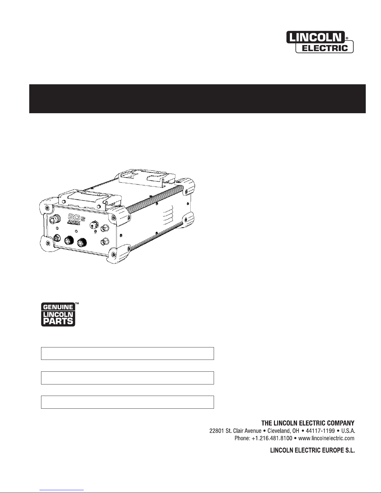
APEX ® 30S CONTROL
For use with machines having Code Numbers:
12835
ORIGINAL INSTRUCTIONS
Register your machine:
www.lincolnelectric.com/register
Authorized Service and Distributor Locator:
www.lincolnelectric.com/locator
Save for future reference
Date Purchased
Code: (ex: 12675)
Serial: (ex: U1060512345)
IM6125 | Issue D ate 02/19
© Lincoln Global, Inc. All Rights Reserved.
Need Help? In the USA and Canada, call
1.800.770.0063 to talk to a Service Representative.
Hours of Operation:
7:00 AM to 5:00 PM (PT) Mon. thru Fri.
After hours?
Use “Ask the Experts” at lincolnelectric.com
A Lincoln Service Representative will contact you
no later than the following business day.
For Service outside the USA and Canada, please call
1.619.628.1022 or e-mail us at:
orbitalsupport@lincolnelectric.com
c/o Balmes, 89 - 80 2
08008 Barcelona
SPAIN
a
Page 2
APEX® 30S
THANK YOU FOR SELECTING
A QUALITY PRODUCT BY
LINCOLN ELEC TRIC.
PLEASE EXAMINE CARTON AND EQUIPMENT FOR
DAMAGE IMMEDIATELY
When this equipment is shipped, title passes to the purchaser
upon receipt by the carrier. Consequently, claims for material
damaged in shipment must be made by the purchaser against the
transportation company at the time the shipment is received.
SAFETY DEPENDS ON YOU
Lincoln arc welding and cutting equipment is designed and built
with safety in mind. However, your overall safety can be increased
by proper installation ... and thoughtful operation on your part.
DO NOT INSTALL, OPERATE OR REPAIR THIS EQUIPMENT
WITHOUT READING THIS MANUAL AND THE SAFETY
PRECAUTIONS CONTAINED THROUGHOUT. And, most importantly,
think before you act and be careful.
WARNING
This statement appears where the information must be followed
exactly to avoid serious personal injury or loss of life.
CAUTION
This statement appears where the information must be followed
to avoid minor personal injury or damage to this equipment.
SAFETY
KEEP YOUR HEAD OUT OF THE FUMES.
DON’T get too close to the arc.
Use corrective lenses if necessary
to stay a reasonable distance
away from the arc.
READ and obey the Safety Data
Sheet (SDS) and the warning label
that appears on all containers of
welding materials.
USE ENOUGH VENTILATION or
exhaust at the arc, or both, to
keep the fumes and gases from
your breathing zone and the general area.
IN A LARGE ROOM OR OUTDOORS, natural ventilation may be
adequate if you keep your head out of the fumes (See below).
USE NATURAL DRAFTS or fans to keep the fumes away
from your face.
If you de velop unusual symptoms, see your supervisor.
Perhaps the welding atmosphere and ventilation system
should be checked.
WEAR CORRECT EYE, EAR &
BODY PROTECTION
PROTECT your eyes and face with welding helmet
properly fitted and with proper grade of filter plate
(See ANSI Z49.1).
PROTECT your body from welding spatter and arc
flash with protective clothing including woolen
clothing, flame-proof apron and gloves, leather
leggings, and high boots.
PROTECT others from splatter, flash, and glare
with protective screens or barriers.
IN SOME AREAS, protection from noise may be appropriate.
BE SURE protective equipment is in good condition.
Also, wear safety glasses in work area
AT ALL TIMES.
SPECIAL SITUATIONS
DO NOT WELD OR CUT containers or materials which previously
had been in contact with hazardous substances unless they are
properly cleaned. This is extremely dangerous.
DO NOT WELD OR CUT painted or plated parts unless special
precautions with ventilation have been taken. They can release
highly toxic fumes or gases.
Additional precautionary measures
PROTECT compressed gas cylinders from excessive heat,
mechanical shocks, and arcs; fasten cylinders so they cannot fall.
BE SURE cylinders are never grounded or part of an
electrical circuit.
REMOVE all potential fire hazards from welding area.
ALWAYS HAVE FIRE FIGHTING EQUIPMENT READY FOR
IMMEDIATE USE AND KNOW HOW TO USE IT.
2
Page 3
APEX® 30S
SECTION A:
WARNINGS
CALIFORNIA PROPOSITION 65 WARNINGS
WARNING: Breathing diesel engine exhaust
exposes you to chemicals known to the State
of California to cause cancer and birth defects,
or other reproductive harm.
• Always start and operate the engine in a
well-ventilated area.
• If in an exposed area, vent the exhaust to the outside.
• Do not modify or tamper with the exhaust system.
• Do not idle the engine except as necessary.
For more information go to
www.P65 warnings.ca.gov/diesel
WARNING: This product, when used for welding or
cutting, produces fumes or gases which contain
chemicals known to the State of California to cause
birth defects and, in some cases, cancer. (California
Health & Safety Code § 25249.5 et seq.
)
with hot engine parts and igniting. Do not spill fuel when filling
tank. If fuel is spilled, wipe it up and do not start engine until
fumes have been eliminated.
1.d. Keep all equipment safety guards, covers
and devices in position and in good repair.
Keep hands, hair, clothing and tools away
from V-belts, gears, fans and all other
moving parts when starting, operating or
repairing equipment.
1.e. In some cases it may be necessary to remove safety guards to
perform required maintenance. Remove guards only when
necessary and replace them when the maintenance requiring
their removal is complete. Always use the greatest care when
working near moving parts.
1.f. Do not put your hands near the engine fan. Do not attempt to
override the governor or idler by pushing on the throttle control
rods while the engine is running.
1.g. To prevent accidentally starting gasoline engines while turning
the engine or welding generator during maintenance work,
disconnect the spark plug wires, distributor cap or magneto wire
as appropriate.
1.h. To avoid scalding, do not remove the radiator
pressure cap when the engine is
hot.
SAFETY
SAFETY
WARNING: Cancer and Reproductive Harm
www.P65warnings.ca.gov
ARC WELDING CAN BE HAZARDOUS. PROTECT
YOURSELF AND OTHERS FROM POSSIBLE SERIOUS
INJURY OR DEATH. KEEP CHILDREN AWAY.
PACEMAKER WEARERS SHOULD CONSULT WITH
THEIR DOCTOR BEFORE OPERATING.
Read and understand the following safety highlights. For
additional safety information, it is strongly recommended
that you purchase a copy of “Safety in Welding & Cutting ANSI Standard Z49.1” from the American Welding Society,
P.O. Box 351040, Miami, Florida 33135 or CSA Standard
W117.2-1974. A Free copy of “Arc Welding Safety” booklet
E205 is available from the Lincoln Electric Company,
22801 St. Clair Avenue, Cleveland, Ohio 44117-1199.
BE SURE THAT ALL INSTALLATION, OPERATION,
MAINTENANCE AND REPAIR PROCEDURES ARE
PERFORMED ONLY BY QUALIFIED INDIVIDUALS.
FOR ENGINE POWERED
EQUIPMENT.
1.a. Turn the engine off before troubleshooting
and maintenance work unless the
maintenance work requires it to be running.
1.b. Operate engines in open, well-ventilated areas or vent the engine
exhaust fumes outdoors.
1.c. Do not add the fuel near an open flame welding
arc or when the engine is running. Stop the
engine and allow it to cool before refueling to
prevent spilled fuel from vaporizing on contact
ELECTRIC AND
MAGNETIC FIELDS MAY
BE DANGEROUS
2.a. Electric current flowing through any conductor
causes localized Electric and Magnetic Fields (EMF).
Welding current creates EMF fields around welding cables
and welding machines
2.b. EMF fields may interfere with some pacemakers, and
welders having a pacemaker should consult their physician
before welding.
2.c. Exposure to EMF fields in welding may have other health effects
which are now not known.
2.d. All welders should use the following procedures in order to
minimize exposure to EMF fields from the welding circuit:
2.d.1. Route the electrode and work cables together - Secure
them with tape when possible.
2.d.2. Never coil the electrode lead around your body.
2.d.3. Do not place your body between the electrode and work
cables. If the electrode cable is on your right side, the
work cable should also be on your right side.
2.d.4. Connect the work cable to the workpiece as close as possible to the area being welded.
2.d.5. Do not work next to welding power source.
3
Page 4
APEX® 30S
SAFETY
SAFETY
ELECTRIC SHOCK
CAN KILL.
3.a. The electrode and work (or ground) circuits are
electrically “hot” when the welder is on. Do
not touch these “hot” parts with your bare skin or wet clothing.
Wear dry, hole-free gloves to insulate hands.
3.b. Insulate yourself from work and ground using dry insulation.
Make certain the insulation is large enough to cover your full area
of physical contact with work and ground.
In addition to the normal safety precautions, if
welding must be performed under electrically
hazardous conditions (in damp locations or while
wearing wet clothing; on metal structures such as
floors, gratings or scaffolds; when in cramped
positions such as sitting, kneeling or lying, if there
is a high risk of unavoidable or accidental contact
with the workpiece or ground) use the following
equipment:
• Semiautomatic DC Constant Voltage (Wire) Welder.
• DC Manual (Stick) Welder.
• AC Welder with Reduced Voltage Control.
3.c. In semiautomatic or automatic wire welding, the electrode,
electrode reel, welding head, nozzle or semiautomatic welding
gun are also electrically “hot”.
3.d. Always be sure the work cable makes a good electrical
connection with the metal being welded. The connection should
be as close as possible to the area being welded.
3.e. Ground the work or metal to be welded to a good electrical (earth)
ground.
3.f. Maintain the electrode holder, work clamp, welding cable and
welding machine in good, safe operating condition. Replace
damaged insulation.
3.g. Never dip the electrode in water for cooling.
3.h. Never simultaneously touch electrically “hot” parts of electrode
holders connected to two welders because voltage
two can be the total of the open circuit voltage of both
welders.
3.i. When working above floor level, use a safety belt to protect
yourself from a fall should you get a shock.
3.j. Also see It ems 6.c. and 8.
between the
ARC RAYS CAN BURN.
4.a. Use a shield with the proper filter and cover plates to protect your
eyes from sparks and the rays of the arc when welding or
observing open arc welding. Headshield and filter lens should
conform to ANSI Z87. I standards.
4.b. Use suitable clothing made from durable flame-resistant material
to protect your skin and that of your helpers from the arc rays.
4.c. Protect other nearby personnel with suitable, non-flammable
screening and/or warn them not to watch the arc nor expose
themselves to the arc rays or to hot spatter or metal.
FUMES AND GASES
CAN BE DANGEROUS.
5.a. Welding may produce fumes and gases
hazardous to health. Avoid breathing these
fumes and gases. When welding, keep your head out of the fume.
Use enough ventilation and/or exhaust at the arc to keep fumes
and gases away from the breathing zone. When welding
hardfacing (see instructions on container or SDS)
or on lead or cadmium plated steel and other
metals or coatings which produce highly toxic
fumes, keep exposure as low as possible and
within applicable OSHA PEL and ACGIH TLV limits
using local exhaust or mechanical ventilation
unless exposure assessments indicate otherwise.
In confined spaces or in some circumstances,
outdoors, a respirator may also be required.
Additional precautions are also required when
welding
on galvanized steel.
5. b. The operation of welding fume control equipment is affected by
various factors including proper use and positioning of the
equipment, maintenance of the equipment and the specific
welding procedure and application involved. Worker exposure
level should be checked upon installation and periodically
thereafter to be certain it is within applicable OSHA PEL and
ACGIH TLV limits.
5.c. Do not weld in locations near chlorinated hydrocarbon vapors
coming from degreasing, cleaning or spraying operations. The
heat and rays of the arc can react with solvent vapors to form
phosgene, a highly toxic gas, and other irritating products.
5.d. Shielding gases used for arc welding can displace air and
injury or death. Always use enough ventilation, especially in
confined areas, to insure breathing air is safe.
5.e. Read and understand the manufacturer’s instructions for this
equipment and the consumables to be used, including the
Safety Data Sheet (SDS) and follow your employer’s safety
practices. SDS forms are available from your welding
distributor or from the manufacturer.
5.f. Also see item 1.b.
cause
4
Page 5
APEX® 30S
SAFETY
SAFETY
WELDING AND CUTTING
SPARKS CAN CAUSE
FIRE OR EXPLOSION.
6.a. Remove fire hazards from the welding area. If
this is not possible, cover them to prevent the welding sparks
from starting a fire. Remember that welding sparks and hot
materials from welding can easily go through small cracks and
openings to adjacent areas. Avoid welding near hydraulic lines.
Have a fire extinguisher readily available.
6.b. Where compressed gases are to be used at the job site, special
precautions should be used to prevent hazardous situations.
Refer to “Safety in Welding and Cutting” (ANSI Standard Z49.1)
and the operating information for the equipment being used.
6.c. When not welding, make certain no part of the electrode circuit is
touching the work or ground. Accidental contact can cause
overheating and create a fire hazard.
6.d. Do not heat, cut or weld tanks, drums or containers until the
proper steps have been taken to insure that such procedures
will not cause flammable or toxic vapors from substances inside.
They can cause an explosion even though they have been
“cleaned”. For information, purchase “Recommended Safe
Practices for the Preparation for Welding and Cutting of
Containers and Piping That Have Held Hazardous Substances”,
AWS F4.1 from the American Welding Society
(see address above).
6.e. Vent hollow castings or containers before heating, cutting or
welding. They may explode.
6.f. Sparks and spatter are thrown from the welding arc. Wear oil free
protective garments such as leather gloves, heavy shirt, cuffless
trousers, high shoes and a cap over your hair. Wear ear plugs
when welding out of position or in confined places. Always wear
safety glasses with side shields when in a welding area.
6.g. Connect the work cable to the work as close to the welding area
as practical. Work cables connected to the building framework or
other locations away from the welding area increase the
possibility of the welding current passing through lifting chains,
crane cables or other alternate circuits. This can create fire
hazards or overheat lifting chains or cables until they fail.
6.h. Also see item 1.c.
6.I. Read and follow NFPA 51B “Standard for Fire Prevention During
Welding, Cutting and Other Hot Work”, available from NFPA, 1
Batterymarch Park, PO box 9101, Quincy, MA 022690-9101.
6.j. Do not use a welding power source for pipe thawing.
CYLINDER MAY EXPLODE IF
DAMAGED.
7.a. Use only compressed gas cylinders containing
the correct shielding gas for the process used
and properly operating regulators designed for
the gas and pressure used. All hoses, fittings,
etc. should be suitable for the application and
maintained in good condition.
7.b. Always keep cylinders in an upright position securely chained to
an undercarriage or fixed support.
7.c. Cylinders should be located:
• Away from areas where they may be struck or subjected
to physical damage.
• A safe distance from arc welding or cutting operations
and any other source of heat, sparks, or flame.
7.d. Never allow the electrode, electrode holder or any other
electrically “hot” parts to touch a cylinder.
7.e. Keep your head and face away from the cylinder valve outlet
when opening the cylinder valve.
7.f. Valve protection caps should always be in place and hand tight
except when the cylinder is in use or connected for use.
7.g. Read and follow the instructions on compressed gas cylinders,
associated equipment, and CGA publication P-l, “Precautions for
Safe Handling of Compressed Gases in Cylinders,” available from
the Compressed Gas Association, 14501 George Carter Way
Chantilly, VA 20151.
FOR ELECTRICALLY
POWERED EQUIPMENT.
8.a. Turn off input power using the disconnect
switch at the fuse box before working on
the equipment.
8.b. Install equipment in accordance with the U.S. National Electrical
Code, all local codes and the manufacturer’s recommendations.
8.c. Ground the equipment in accordance with the U.S. National
Electrical Code and the manufacturer’s recommendations.
Refer to
http://www.lincolnelectric.com/safety
for additional safety information.
5
5
Page 6

APEX® 30S
SAFETY
ELECTROMAGNETIC
COMPATIBILITY (EMC)
CONFORMANCE
Products displaying the CE mark are in conformity with European Community
Council Directive of 3 May 1989 on the approximation of the laws of the
Member States relating to electromagnetic compatibility (2014/30/UE). It
was manufactured in conformity with a national standard that implements a
harmonized standard: EN 60974-10
Electromagnetic Compatibility (EMC) Product Standard for Arc Welding
Equipment. It is for use with other Lincoln Electric equipment. It is designed
for industrial and professional use.
INTRODUCTION
All electrical equipment generates small amounts of electromagnetic
emission. Electrical emission may be transmitted through power lines or
radiated through space, similar to a radio transmitter. When emissions are
received by other equipment, electrical interference may result. Electrical
emissions may affect many kinds of electrical equipment; other nearby
welding equipment, radio and TV reception, numerical controlled machines,
telephone systems, computers, etc. Be aware that interference may result
and extra precautions may be required when a welding power source is used
in a domestic establishment.
INSTALLATION AND USE
The user is responsible for installing and using the welding equipment
according to the manufacturer’s instructions. If electromagnetic disturbances
are detected then it shall be the responsibility of the user of the welding
equipment to resolve the situation with the technical assistance of the
manufacturer. In some cases this remedial action may be as simple as
earthing (grounding) the welding circuit, see Note. In other cases it could
involve construction of an electromagnetic screen enclosing the power source
and the work complete with associated input filters. In all cases electromagnetic disturbances must be reduced to the point where they are no longer
troublesome.
Note: The welding circuit may or may not be earthed for safety reasons according to national codes.
Changing the earthing arrangements should only be authorized by a person who is competent to
access whether the changes will increase the risk of injury, e.g., by allowing parallel welding current
return paths which may damage the earth circuits of other equipment.
ASSESSMENT OF AREA
Before installing welding equipment, the user shall make an assessment of
potential electromagnetic problems in the surrounding area. The following
shall be taken into account:
a. Other supply cables, control cables, signaling and telephone cables; above, below
and adjacent to the welding equipment;
b. radio and television transmitters and receivers;
c. computer and other control equipment;
d. safety critical equipment, e.g., guarding of industrial equipment;
e. the health of the people around, e.g., the use of pacemakers and hearing aids;
f. equipment used for calibration or measurement and
g. the immunity of other equipment in the environment. The user shall ensure that other
equipment being used in the environment is compatible. This may require additional
protection measures including:
h. the time of day that welding or other activities are to be carried out.
The size of the surrounding area to be considered will depend on the
structure of the building and other activities that are taking place. The
surrounding area may extend beyond the boundaries of the premises.
METHODS OF REDUCING EMISSIONS
Mains Supply
Welding equipment should be connected to the mains supply according
to the manufacturer’s recommendations. If interference occurs, it may be
necessary to take additional precautions such as filtering of the mains supply.
Consideration should be given to shielding the supply cable of permanently
installed welding equipment, in metallic conduit or equivalent. Shielding
should be electrically continuous throughout its length. The shielding should
be connected to the welding power source so that good electrical contact is
maintained between the conduit and the welding power source enclosure.
Maintenance of the Welding Equipment
The welding equipment should be routinely maintained according to the
manufacturer’s recommendations. All access and service doors and covers
should be closed and properly fastened when the welding equipment is in
operation. The welding equipment should not be modified in any way except
for those changes and adjustments covered in the manufacturers instructions.
In particular, the spark gaps of arc striking and stabilizing devices should be
adjusted and maintained according to the manufacturer’s recommendations.
Welding Cables
The welding cables should be kept as short as possible and should be
positioned close together, running at or close to floor level.
Equipotential Bonding
Bonding of all metallic components in the welding installation and adjacent
to it should be considered. However, metallic components bonded to the
work piece will increase the risk that the operator could receive a shock by
touching these metallic components and the electrode at the same time. The
operator should be insulated from all such bonded metallic components.
Earthing of the Workpiece
Where the workpiece is not bonded to earth for electrical safety, not
connected to earth because of its size and position, e.g., ships hull or
building steelwork, a connection bonding the workpiece to earth may reduce
emissions in some, but not all instances. Care should be taken to prevent the
earthing of the work piece increasing the risk of injury to users, or damage to
other electrical equipment. Where necessary, the connection of the workpiece
to earth should be made by a direct connection to the work piece, but in some
countries where direct connection is not permitted, the bonding should be
achieved by suitable capacitance, selected according to national regulations.
Screening and Shielding
Selective screening and shielding of other cables and equipment in the
surrounding area may alleviate problems of interference. Screening of the
entire welding installation may be considered for special applications.
1 Portions of the preceding text are contained in EN 60974-10: “Electromagnetic
Compatibility (EMC) product standard for arc welding equipment.”
6
Page 7

APEX® 30S
Technical Specications APEX 30S ....................................................................................................................... A-1
Safety Precautions ................................................................................................................................................. A-2
Proper Handling ................................................................................................................................................. A-2
Operation ........................................................................................................................................................... A-2
APEX 30S System .................................................................................................................................................... B-1
Basic Information ............................................................................................................................................... B-1
Front Panel .................................................................................................................................................. B-1
Back Panel Connections ............................................................................................................................. B-2
Installation ................................................................................................................................................... B-2
System Cart ................................................................................................................................................ B-2
Optional Modules ........................................................................................................................................ B-2
Power Source.............................................................................................................................................. B-3
Inverter Cart Top Bracket ........................................................................................................................... B-3
Lift Cart Top Bracket .................................................................................................................................. B-3
Cable Installation ........................................................................................................................................ B-4
Cable List .................................................................................................................................................... B-4
Inverter and Lift Cart Cable Installation ...................................................................................................... B-5
Shielding Gas Connection .......................................................................................................................... B-6
Maintenance ............................................................................................................................................................ D-1
Maintenance Schedule ....................................................................................................................................... D-1
Every Shift ................................................................................................................................................... D-1
Monthly ....................................................................................................................................................... D-1
Using the Status LED to Troubleshoot System Problems .................................................................................. F-1
Weld Head Status LED Error Codes .................................................................................................................. F-2
Diagrams .................................................................................................................................................................. G-1
APEX 30S PARTS MANUAL ................................................................................................................................... P-1
TABLE OF CONTENTS
Page 8

Technical Specications APEX® 30S
APEX 30S Control Unit
Product Number
K52217-1
Input Power 40 VDC
Rated Output 24V 9A
Input Current 10A Max
Dimensions L x W x H (in.) 25.33 x 11 x 14.33
Dimensions L x W x H (mm) 644.4 x 279.4 x 363.2
Net Weight lbs. (kg) 36.1 (16.4)
Temperature Ranges
Operating Temperature Range
32F to 122F (0C - 50C)
A -weighted emission sound pressure level: less than 70 db (A)
Storage Temperature Range
-22F to 140F (-30C - 60C)
INSTALLATIONAPEX® 30S
A-1
Page 9

Safety Precautions
Read entire manual before installation or operation.
WARNING
ELECTRIC SHOCK CAN KILL
• Only qualed personnel
should perform this
installation.
• Turn the input power
OFF at the disconnect
switch or fuse box
before working on this
equipment turn off the input power to any other
equipment connected to the welding system at
the disconnect switch or fuse box before working
on the equipment.
• Do not touch electrically hot parts.
• Always connect the power supply grounding lug
to a proper safety (Earth) ground.
INSTALLATIONAPEX® 30S
Proper Handling
Do not attempt to pick up, move or manipulate the
control unit by the cables.
Always operate the control unit on stable, at and
level surfaces with the bottom or side rails facing the
ground. Be sure to leave adequate room to open the
door to the wire feed assembly. Unplug the control
unit when not in use. Do not place on wet ground or
in puddles.
The system cart is designed for at even surfaces.
Do no overload cart.
Operation
Read entire manual before operation.
Only operate while on rm level surface or attached
to a system cart. Always verify that the system cart is
secured in place before operation.
Keep hands away from weld head while in operation.
CAUTION
Never unplug or plug in control cables to the tractor
while the system is powered on.
Verify that the system is properly grounded before
beginning to weld.
Refer to the individual system manuals for additional
instructions.
A-2
Page 10
APEX 30S System
Basic Information
The APEX
APEX 3 Series family of controllers and is the rst
of its kind that can be used for GMAW/FCAW and
GTAW welding.
Moving from at track, plate or other structural beams
to an orbital track takes only a simple weld head
adjustment. Synchronizing amps, volts, travel speed,
and oscillation, the APEX 30S controller can be utilized
for more welding applications than before.
The APEX 30S controller also reduces the need for
auxiliary components by incorporating a gas solenoid
and ow sensor within the controller, minimizing cable
clutter and reducing the overall footprint of the
congured system.
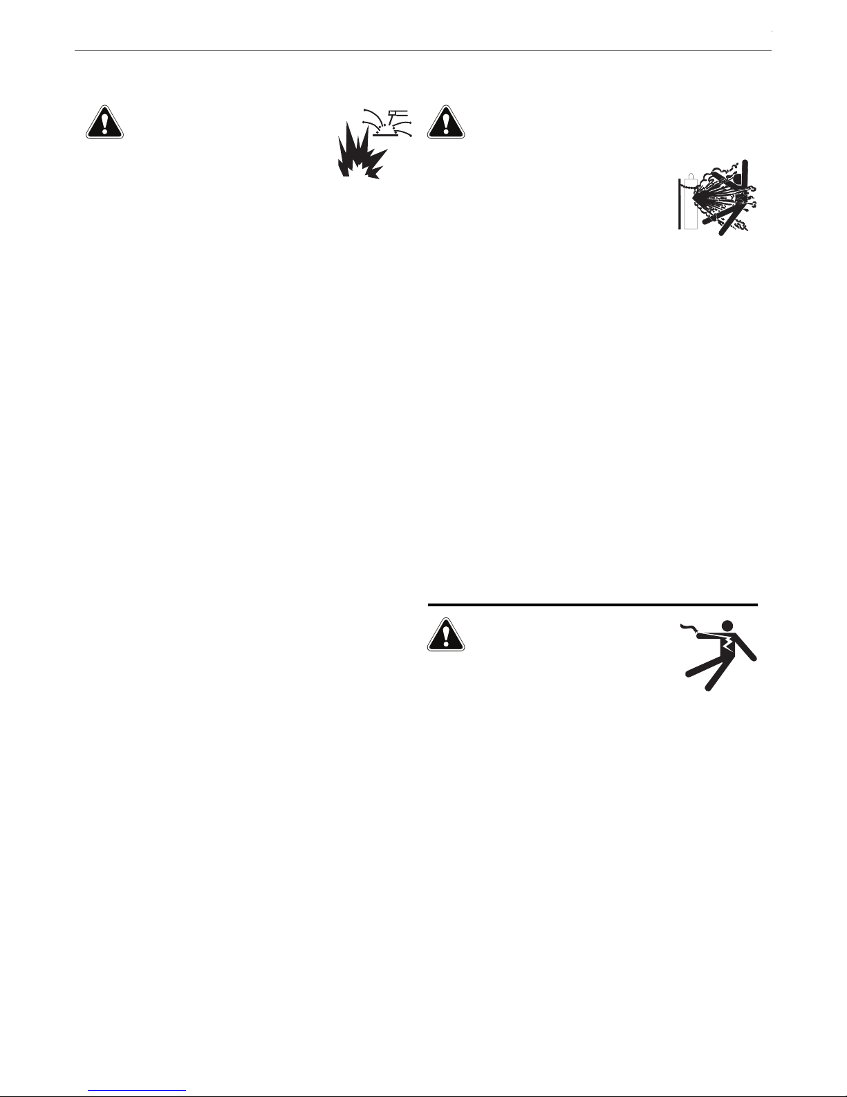
The status of APEX 30S controller can be monitored on
the front panel – see FIGURE 2 - Front Panel.
Additionally, the front of the control has a halt button,
two connections for pendants, a weld head connector,
and a USB port.
30S Control Unit (K52217-1) is part of the
FIGURE 1 - APEX 30S
INSTALLATIONAPEX® 30S
FIGURE 2 - Front Panel
Front Panel
For all front panel connections – see FIGURE 2 -
Front Panel.
1. Halt Switch - Removes power from the weld head,
pendant and any ArcLink® device connected to the
front of the 30S controller. The system will remain
off until the switch is rotated clockwise. This switch
does not shut off the power source.
2. Motion Network Status - The network status light
will show green if all motion systems are operational.
3. Weld Head Connector - Connection from the
APEX 30M to the weld head.
4. ArcLink Out - Two ArcLink cable connections for
pendants or other ArcLink devices.
5. ArcLink Status - The ArcLink status light will be
green if all ArcLink systems are operational.
6. USB - Welding programs and data can be saved
and loaded via USB.
7. Gas Outputs - Two connections for gas flow that
have independent solenoid valves and flow sensors.
B-1
Page 11
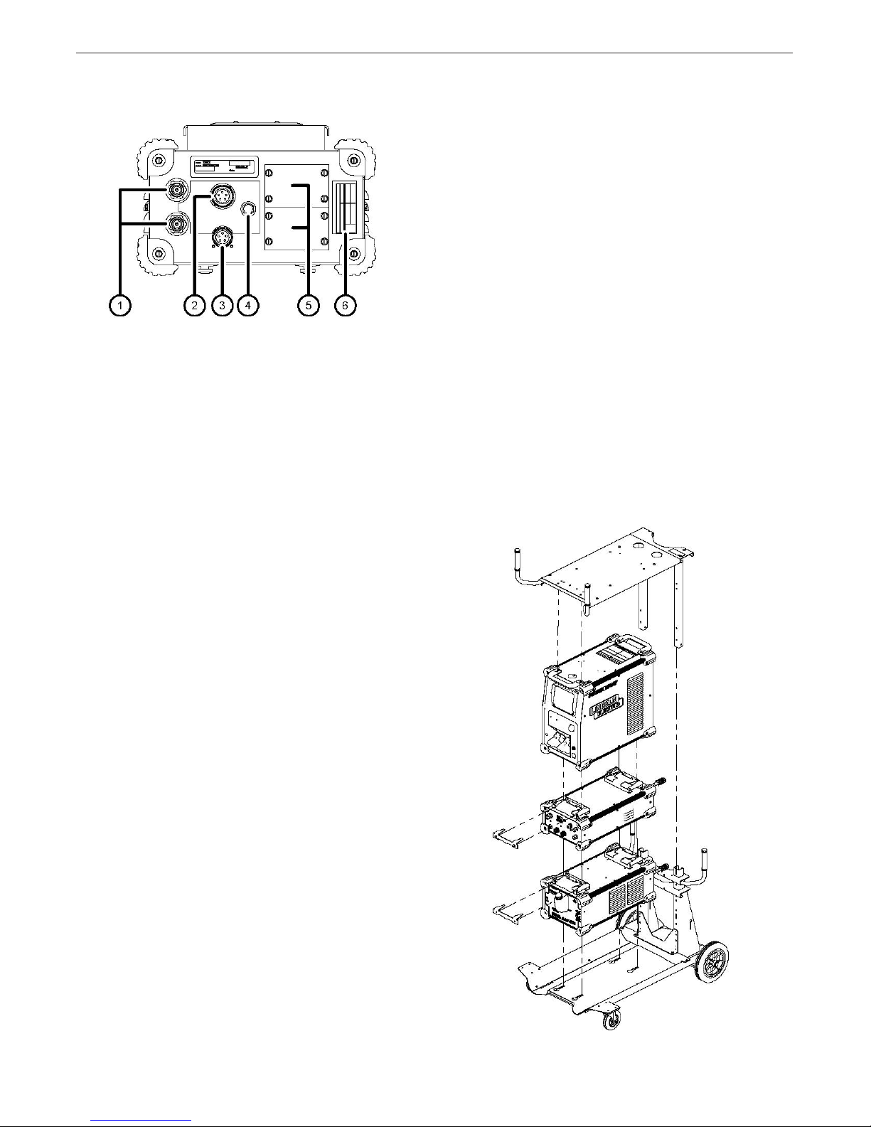
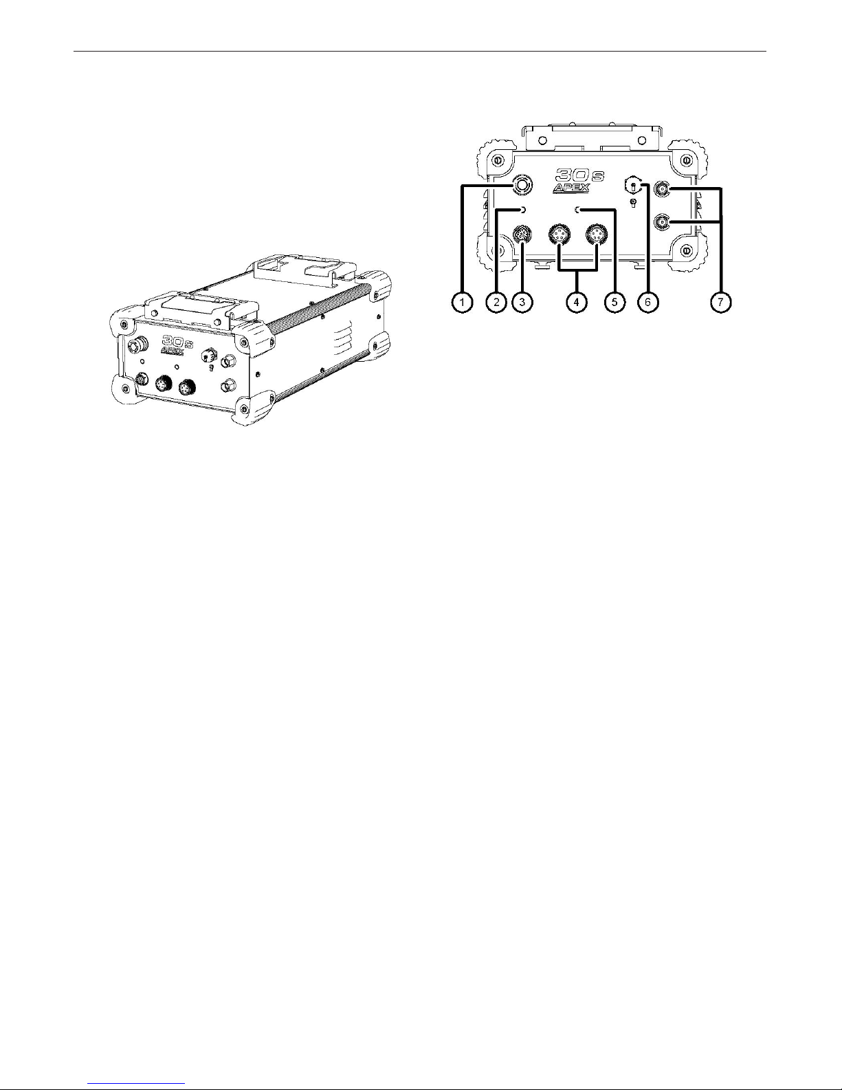
Figure 3 - Back Panel
Back Panel Connections
For all bank panel connections – see FIGURE 4 -
Back Panel.
1. Gas Inputs - Welding gas supplied to the system.
2. ArcLink In - The ArcLink connection from the
power source or other ArcLink enabled device
3. ArcLink Out - ArcLink connection for auxilliary
device.
4. Breaker 10A - Will trip in overpower situations;
push to re-engage.
5. Upgrade Panels - Two panels where upgrade kits
can be installed, such as the ArcLink Bridge Kit for
enabling Hot Wire TIG.
6. Rating Plate - Contains technical information for
the machine.
INSTALLATIONAPEX® 30S
Installation
On a standard APEX 30S Control, the components
are designed to be installed on the system cart in a
specic order.
System Cart
The system cart comes fully assembled when ordered
as a part of a complete system. If ordered separately,
it may require additional assembly. Please refer to
system cart assembly instructions for complete stepby-step instructions.
Optional Modules
The optional modules are installed in both system carts
before the power source – see FIGURE 4 - Inverter
Cart System Assembly and FIGURE 5 (on page B-3)
- Lift Cart System Assembly. Set the module into the
mounting holes provided and push backwards to seat
the module.
Install the bracket to lock the module in place.
Optional modules have brackets in the top to support
the power source.
FIGURE 4 - Inverter Cart System Assembly
B-2
Page 12
INSTALLATIONAPEX® 30S
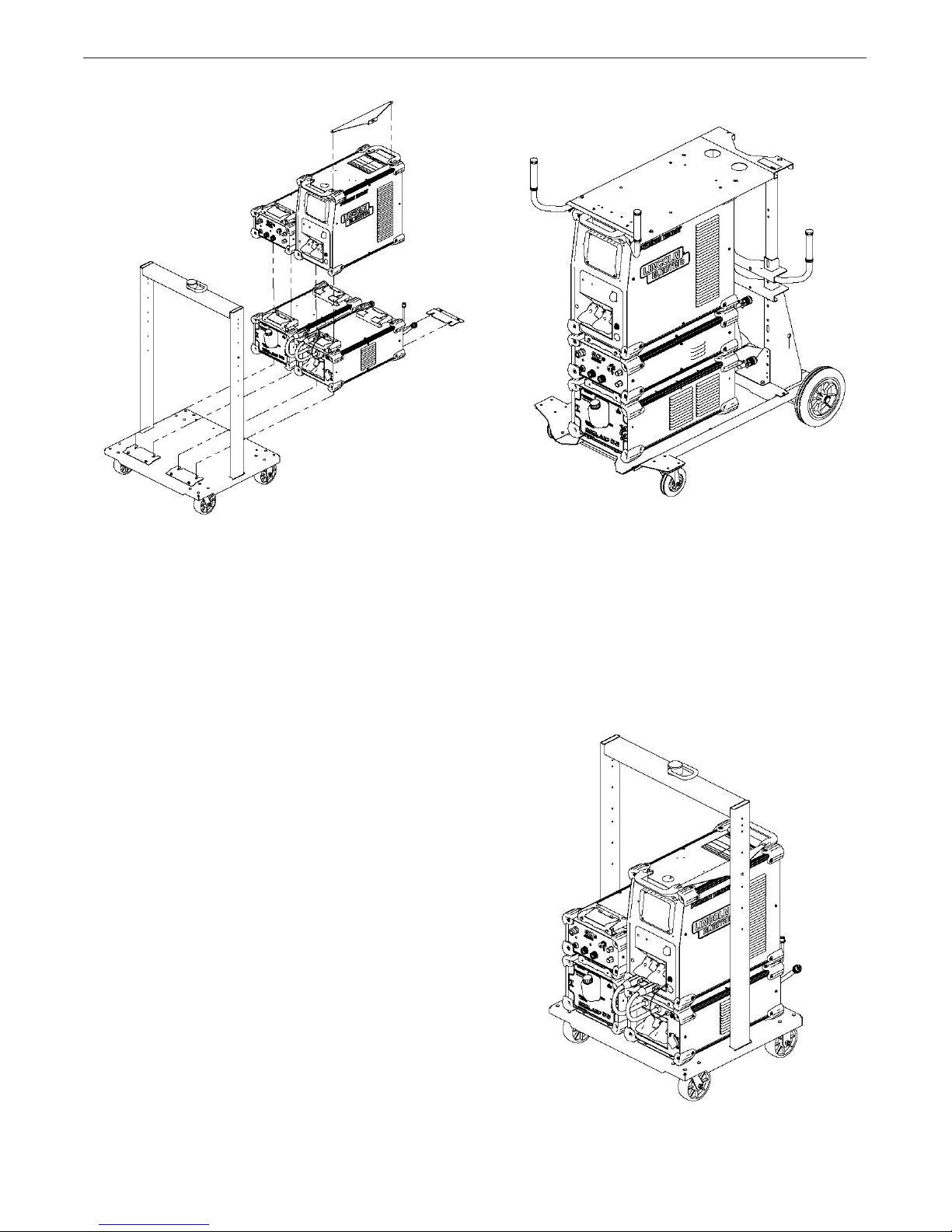
FIGURE 5 - Lift Cart System Assembly
Power Source
The power source will be installed either onto the base
or on top of the optional modules (if installed). Set the
power source into the mounting holes provided and
push backwards to seat the module.
Cart Top Bracket – Inverter Cart
To afx the Power Wave® power source in place,
attach the top bracket of the cart. Remove the screws
from the top of the Power Wave front handle. Secure the
top bracket of the cart with the provided screws.Adjust
the sliding back brace of the cart so that it is in line with
the cart top. Verify that the cart top lines up with both
the screw holes on the sliding back brace and the holes
from the handles removed earlier. Secure the
top bracket in place. See FIGURE 4 (on page B-2)
- Inverter Cart System Assembly.
FIGURE 6 - Inverter Cart System Complete
Cart Top Bracket – Lift Cart
To afx the Power Wave power source in place,
attach the support bracket to the Power Wave power
source using the existing screws from the Power Wave
unit’s handle. Then secure the bracket to the cart post
using the included hardware. See FIGURE 5 - Lift Cart
System Assembly.
FIGURE 7 - Lift Cart System Complete
B-3
Page 13

INSTALLATIONAPEX® 30S
Cable Installation
The system is shipped out with cables connected,
how ever the components can be ordered separately
and installed by the end user, or the cables and components may be removed during routine maintenance.
For the complete system cable map – see FIGURES 8
and 9 - System Assembly.
Note:
• Always use the shortest cable lengths possible.
DO NOT coil excess cable. It is recommended that
the total length of control cable does not exceed
100’ (30.5M). The use of non-standard cables in
excess of 25’ (7.5M) can lead to communication
problems (system shut downs), poor motor acceleration (poor arc starting), and low wire driving force
(wire feeding problems).
• Best results will be obtained when the control cables
are routed separate from the weld cables. This minimizes the possibility of interference between the
high currents owing through the weld cables and
the low level signals in the control cables.:
Cable List
1. Pendant Cable - Connects from the pendant to
the control unit
2. Control Cable - Connects from the weld head to
the control unit
3. Torch Assembly - Runs from the control unit
out to the weld head. Includes power, sense lead,
gas and water lines
4. Work Cable* - Connects from the POWER WAVE
unit (or Advanced Process Module if installed) to
the work piece
5. 3-Phase Power Cable* - Connects power supply
to facility power (refer to power supply manual for
installation)
6. Gas Hose* - Supplies gas to the system from
external source
7. Ethernet Cable* - Optional cable to connect the
power supply to a local area network for added
system functionality
* Indicates items not included with the system
ArcLink cables can be used to extend the pendant
cable length.
B-4
Page 14

INSTALLATIONAPEX® 30S
7
4
5
3
GAS
1
2
5
FACILITY
POWER
FIGURE 8 - Inverter Cart System
7 5
3
2
1
4
FACILITY
POWER
GAS
6
FIGURE 9 - Lift Cart System
B-5
Page 15

Shielding Gas Connection
WARNING
CYLINDER MAY EXPLODE IF DAMAGED.
• Keep cylinder upright and chained to support.
• Keep cylinder away from areas where it may be damaged.
• Never lift welder with cylinder attached.
• Never allow welding electrode to touch cylinder.
• Keep cylinder away from welding or other live electrical circuits
•
THE BUILD UP OF SHIELDING GAS MAY HARM HEALTH OR KILL.
• Shut off shielding gas supply when not in use.
• See American National Standard Z-49.1,
“Safety in Welding and Cutting”
Published by the American Welding Society.
MAXIMUM INLET PRESSURE IS 100 PSI. (6.9 BAR.)
INSTALLATIONAPEX® 30S
.
Install the shielding gas supply as follows:
1. Secure the cylinder to prevent it from falling.
2. Remove the cylinder cap. Inspect the cylinder valves
and regulator for damaged threads, dirt, dust, oil or
grease. Remove dust and dirt with a clean cloth. DO
NOT ATTACH THE REGULATOR IF OIL, GREASE OR
DAMAGE IS PRESENT! Inform your gas supplier of this
condition.
3. Stand to one side away from the outlet and open the cylinder valve for an instant. This blows away any dust or dirt
which may have accumulated in the valve outlet.
4. Attach the flow regulator to the cylinder valve and tighten
the union nut(s) securely with a wrench.
Note: if connecting to 100 percent CO2 cylinder, insert
regulator adapter between regulator and cylinder valve.
If adapter is equipped with a plastic washer, be sure it is
seated for connection to the CO2 cylinder.
5. Attach one end of the inlet hose to the outlet fitting of the
flow regulator. Attach the other end to the welding system
shielding gas inlet. Tighten the union nuts with a wrench.
6. Before opening the cylinder valve, turn the regulator
adjusting knob counterclockwise until the adjusting spring
pressure is released.
7. Standing to one side, open the cylinder valve slowly a
fraction of a turn. When the cylinder pressure gage stops
moving, open the valve fully.
8. The flow regulator is adjustable. Adjust it to the flow rate
recommended for the procedure and process being used
before making a weld.
B-6
Page 16

APEX® 30S
Maintenance
The APEX 30S Control is designed for trouble-free
operation and normally requires minimal preventive
care and cleaning. This section provides instructions
for maintaining user serviceable items. The suggested
repair procedure for all such items is to remove and
replace defective assemblies or parts. When users
and/or service personnel are not familiar with electrical
and electronic equipment, the product should be
returned to the factory or serviced by
factory authorized representatives.
Maintenance Schedule
The maintenance schedule is suggested as a
guideline for proper system maintenance. More
stringent maintenance requirements may be required
depending on the work being performed and the
requirements of the customer for whom the work is
performed. All maintenance schedules are based on
a 40-hour work week.
MAINTENANCE
Any excess play in parts or equipment should be
noted and reported to an authorized repair facility. Any
anomalous activity, such as motor hesitation, clicking
or other noises, or anything out of the ordinary should
be noted and reported to an authorized repair facility.
Every Shift
• Check lines, cables, and hoses for loose connections
and worn areas.
Monthly
• Examine all hose connections to verify that there
are no gas leaks. Make sure all cables are seated
correctly and that there is no visible wear and tear
to any connector or associated cables.
D-1
Page 17

APEX® 30S
TROUBLE SHOOTING
Observe all Safety Guidelines detailed throughout this manual
Using the Status LED to Troubleshoot System Problems
The APEX 30S controller and the Power Wave unit are equipped with status LED. If a problem occurs, it is
important to note the condition of the status LED – see FIGURE 2 - Front Panel, item 5 on page B-1. Before
cycling power to the system, check the power source status LED for error sequences as noted below.
Included in this section is information about the Weld Head and ArcLink device status LEDs and a basic troubleshooting chart for both the machine and the weld performance. The LEDs are dual-colored and indicate system
errors. Normal operation for each is steady green. Error conditions are indicated in FIGURE 10- Status LED
Light Conditions.
FIGURE 10 - Status LED Light Conditions
LIGHT CONDITION MEANING
Steady Green System is OK. The power source is operational and is communicating
normally with all peripheral equipment connected to its ArcLink device network.
Blinking Green Occurs during power up or a system reset and indicates the Power Wave unit is
mapped (identifying) each component in the system. This is normal for the rst
1 to 60 seconds after the power is turned on, or if the system conguration is
changed during operation.
Fast Blinking Green Under normal conditions it indicates that Auto-mapping has failed. It is also used
by Weld Manager Utilities. More information is available on the Service Navigator
CDs or visit www.powerwavesoftware.com.
Alternating Red and Green Non-recoverable system fault. If the status lights are ashing any combination of
red and green, errors are present. Read and note the error code(s) before turning
off the machine.
Error code interpretation through the status light is detailed in the service manual. Individual code digits are ashed in red with a long pause between digits. If
more than one code is present, the codes will be separated by a green light.
Only active error conditions are accessible through the status light.
Error codes can also be retrieved with the Weld Manager Utility, included on the
Service Navigator CDs. For the most updated error code log information, please
visit: www.powerwavesoftware.com.
To clear the active error(s), turn the power source off and back on to reset the
system.
Steady Red Not applicable.
Blinking Red Not applicable.
If for any reason you do not understand the test procedures or are unable to perform the tests/repairs safely, contact
your Local Lincoln Authorized Field Service Facility for technical troubleshooting assistance before you proceed.
CAUTION
F-1
Page 18

APEX® 30S
Observe all Safety Guidelines detailed throughout this manual
Weld Head Status LED Error Codes
Error ID Description Potential Solution
TROUBLE SHOOTING
5-3-1
5-3-3
5-3-4
5-3-5
5-3-6 Calibrated fault with oscillation Check weld head cable and cycle power.
5-3-7 Calibrated fault with height Check weld head cable and cycle power.
5-3-8 Wire drive timeout Check weld head cable and cycle power.
5-3-9 “Other” Cycle power.
5-3-6 Calibrated fault with oscillation Check weld head cable and cycle power.
5-3-7 Calibration fault with height Check weld head cable and cycle power.
5-3-8 Wire drive timeout Check weld head cable and cycle power.
Weld head network not recognized by
controller. Weld head has no power.
Communication with oscillation motor
has halted.
Communication with height motor has
halted.
Communication with travel motor has
halted.
Check to make sure the weld head cable is plugged in and
that the APEX 30S controller has power via 110V AC aux
connector (if applicable). Cycle power to Power Wave unit.
Check weld head cable for potential bad connections.
Cycle power.
Check weld head cable for potential bad connections.
Cycle power.
Check weld head cable for potential bad connections.
Cycle power.
5-3-9 “Other” Cycle power.
5-4-1 Oscillation motor following error
5-4-2 Oscillation motor overcurrent
5-4-3 Oscillation motor overheat Check welding conditions. Turn off power for 5 minutes.
5-4-4 Oscillation communications fault
5-4-5 Oscillation communications off
5-4-6
5-4-7 Oscillation motor overvoltage
5-4-8 Oscillation motor position sensor error
5-4-9 Oscillation fault unknown
Oscillation was moved passed
programmed limit
Check for resistance on the torch arm. Oscillation speeds
too high.
Check power supplies, cycle power. Clear any resistance/
debris from track and the weld head arm.
Check weld head cable and make sure no extra power/
noise is being discharged into the weld head.
Check weld head cable and make sure no extra power/
noise is being discharged into the weld head.
Recalibrate the system/cycle power. Make sure weld head
arm moves all the way in and you have full range of movement.
Check power supplies, cycle power. Clear any resistance/
debris from track and the weld head arm.
Cycle power. Make sure internal motor controller wire
harnesses and connectors are secure.
Check all of the above items. Cycle power.
Contact a Service Representative at: 800-770-0063
CAUTION
If for any reason you do not understand the test procedures or are unable to perform the tests/repairs safely, contact
your Local Lincoln Authorized Field Service Facility for technical troubleshooting assistance before you proceed.
F-2
Page 19

APEX® 30S
TROUBLE SHOOTING
Observe all Safety Guidelines detailed throughout this manual
5-5-1 Height motor following error
5-5-2 Height motor overcurrent
5-5-3 Height motor overheat Check welding conditions. Turn off power for 5 minutes.
5-5-4 Height communications fault
5-5-5 Height communications off
5-5-6
5-5-7 Height motor overvoltage
5-5-8 Height motor position sensor error
5-5-9 Height fault unknown
5-6-1 Travel motor following error
5-6-2 Travel motor overcurrent
Height was moved passed programmed
limit
Check for resistance on the torch arm. Height movement
speeds too high.
Check power supplies. Cycle power. Clear any debris from
the track and the weld head arm.
Check weld head cable and make sure no extra power/
noise is being discharged into the weld head.
Check weld head cable and make sure no extra power/
noise is being discharged into the weld head.
Recalibrate the system/cycle power. Make sure weld head
arm moves all the way in and you have full range of movement. Check Setup.
Check power supplies, cycle power. Clear any resistance/
debris from track and the weld head arm.
Cycle power. Make sure internal motor controller wire
harnesses and connectors are secure.
Check all of the above items; cycle power. Contact a
Service Representative at 800-770-0063.
Check for resistance on the torch arm. Travel speeds too
high.
Check power supplies, cycle power. Clear any resistance/
debris from track and the weld head arm.
5-6-3 Travel motor overheat Check welding conditions. Turn off power for 5 minutes.
5-6-4 Travel communications fault
5-6-5 Travel communications off
5-6-6
5-6-7 Travel motor overvoltage
5-6-8 Travel motor position sensor error
5-6-9 Travel fault unknown
5-7-1 Wire motor following error
5-7-2 Wire motor overcurrent
5-7-3 Wire motor overheat
5-7-4 Wire communications fault
5-7-5 Wire communications off
Travel was moved passed programmed
limit
Check weld head cable and make sure no extra power /
noise is being discharged into the weld head.
Check weld head cable and make sure no extra power /
noise is being discharged into the weld head.
Recalibrate the system/cycle power. Make sure you can
jog travel along your track.
Check power supplies, cycle power. Clear any resistance/
debris from track and the weld head arm.
Cycle power. Make sure internal motor controller wire harnesses and connectors are secure.
Check all of the above items. Cycle Power. Contact a
Service Representative at the number on the cover of this
manual.
Check for resistance when pulling wire through the liner.
Wire speeds too high.
Check power supplies, cycle power. Check for wire birdnest. Check for resistance when pulling wire through the
liner.
Check welding conditions. Turn off power for 5 minutes.
Check for resistance when pulling wire through the liner.
Check Weld head cable and make sure no extra power /
noise is being discharged into the Weld head.
Check Weld head cable and make sure no extra power /
noise is being discharged into the Weld head.
If for any reason you do not understand the test procedures or are unable to perform the tests/repairs safely, contact
your Local Lincoln Authorized Field Service Facility for technical troubleshooting assistance before you proceed.
CAUTION
F-3
Page 20

APEX® 30S
TROUBLE SHOOTING
Observe all Safety Guidelines detailed throughout this manual
5-7-6 Wire motor / encoder issue
5-7-7 Wire motor overvoltage
5-7-8 Wire motor / encoder issue
5-7-9 Wire fault unknown
6-3-3-1
8-1 Motor Overload (Long Term)
8-2 Motor Overload (Short Term)
8-3 Shutdown #1 is open Contact a Service Representative at: 800-770-0063.
8-4 Shutdown #2 is open Contact a Service Representative at 800-770-0063.
Unstable or “noisy” WFS feedback
signal
Cycle power to the system and allow the system to
recalibrate. Make sure you can jog wire in Jog mode.
Check power supplies, cycle power.
Check for wire bird-nest.
Check for resistance when pulling wire through the liner.
Cycle power to the system and allow the system to recalibrate. Make sure you can jog wire in Jog mode.
Check all of the above items. Cycle Power.
Contact a Service Representative at: 800-770-0063.
Check the cables and connections. Cycle power.
Check the electrode feeds easily through feed system.
Verify the wire reel bracket is not too tight. Verify the
quality of electrode. We recommend only Lincoln Electric
brand..
Check that motor can turn freely when idle arm is open.
Check gears for dirt and debris. Check for error 8.1.
If for any reason you do not understand the test procedures or are unable to perform the tests/repairs safely, contact
your Local Lincoln Authorized Field Service Facility for technical troubleshooting assistance before you proceed.
CAUTION
F-4
Page 21
APEX® 30S
1234567
8
J5
1234567
8J812345
6
J7
3
4
56
7
8910
21
J9
2
1
J13
2
1
J12
2
1
J15
2
1
J14
4
3
21
J1
4
3
21
J2
4
3
21
J3
4
3
21
J4
1
2
3
4
5
6
7
8
J9
1
2
3
4
5
6
7
8
J12
1
2
3
4
5
6
7
8
J10
123
4J1123
4
J2
3
4
5
6
7
89
10
2
1
J11
8
7
6
5
4
3
2
1
J3
12
3
4
56
J7
3456789
10
2
1
J8
65432
1J465432
1
J6
65432
1
J5
8
7
6
5
4
321 9 10
J10
123
4
5
6
J6
12
J17
CANOPEN BRIDGE
G8355-1
OUT
+
24V POWER
SUPPLY
4
3
2
1
CON1
4
3
2
1
CON2
4
3
2
1
CON3
4
3
2
1
CON4
SWITCHBOX PCB
G8621-1
123
J1
FLOW METER
TOP
A
123
J1
BLK2
BLK1
BLU2
BLU1
BRN2
BRN1
BRN1
BLK1
BLU1
BRN2
BLK2
BLU2
S32582
3456789
10
2
1
J9
USB PCB
G7417-1
S30452
12345J112345
J2
541E
542E
500E
540E
1
2
345
6
CON5
1234567
8
CON3
4
3
2
1
CON4
CANOPEN
LED
ARCLINK
LED
S31032
S31032
SHLD
3055
3056
3057
3058
S30466
1
CON1
1
CON2
CB1
S32571
S32572
3123D
3125D
3123D
3125D
S32575
FAN
3123E
3125E
S32585
3092A
3091B
3095A
3092A
3091B
3094B
3094B
3095A
S32576
EDCBA
BLK
BLK
WHT
WHT
541E
542E
500E
540E
M23389
541E
542E
500E
540E
M23389
541E
542E
500E
540E
M23682
500F
540F
500F
540F
500G
540G
24V/40V DIST PCB
S31010-1
4700pf
3000V
C3
541E
540E
500E
542E
1
2
Pole 1
1
2
Pole 2
STOP SW NC
S32573
52C
3140
RED
BLK
3140
A
B
C
D
E
M23501
ARCLINK OUT
M22438
WHT
ORN
BLU
53A
54A
51B
52B
541E
542E
500E
540E
M23389
540A
500A
542A
541A
3103
3104
3110
3111
3109
3112
K
L
J
M
F
E
H
G
A
B
C
D
WELD HEAD OUTPUT
M23672
3101
3102
3101
3102
3141
3141
3142
3142
S32574
67C
S32581
3125
RED 3124 3125
S32583
4700pf
3000V
C2
A
B
C
D
E
ARCLINK OUT
M23501
811B
812B
814B
813B
67B
811B
812B
813B
814B
67B
67B
51B
51
M23684
EDCBA
53
6752515467A
54A
53A
67A
M23672
L4
L5
4
3
2
1
CON1
4
3
2
1
CON24
321
CON3
432
1 CON4
AL DIST PCB
S31042-1
541E
540E
500E
542E
541A
542A
500A
540A
811B
812B
814B
813B
811B
812B
813B
814B
L6
L7
67C
67C
67B
USB A
FEMALE
G
R
G
R
4700pf
3000V
C1
A
B
FLOW METER
BOTTOM
B
3103
3110
3109
3104
3111
3112
SOLENOID
TOP
A
SOLENOID
BOTTOM
B
3124
OUT
-
IN
-
IN
+
BLK
BLK
RED
541E
542E
500E
540E
1
2
3
4
5
6
P16
6
5
4
3
2
1
54
53
67
WHT
ORN
BLU
BLK
52B
52C
L9
L8
52
4700pf
3000V
C4
AL DIST PCB
S31042-1
L1
L2
L3
ARCLINK OUT
ARCLINK IN
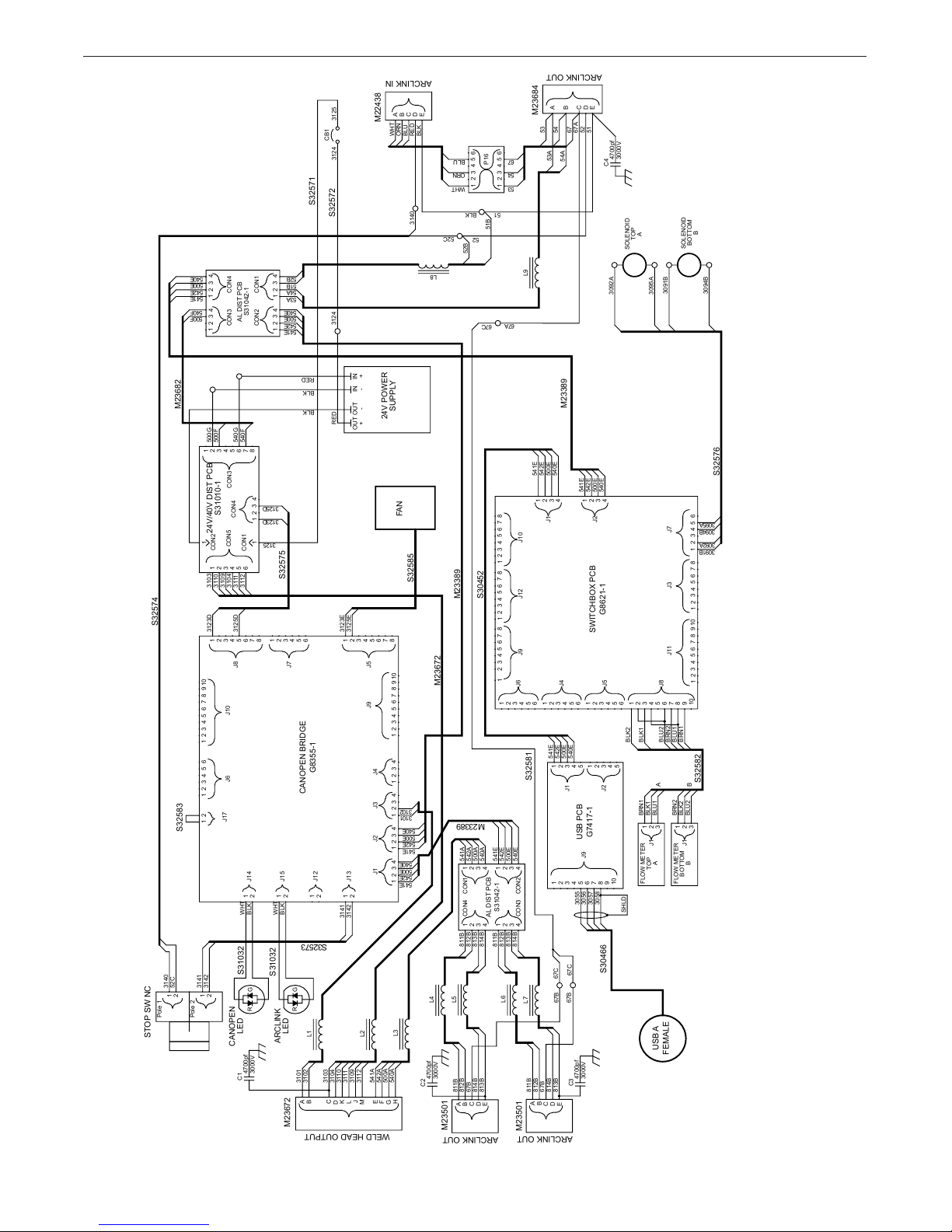
DIAGRAMS
Wiring Diagram 12835
G-1
NOTE: This diagram is for reference only. It may not be accurate for all machines covered by this manual. If the diagram is illegible, write to the Service Department for
a replacement. Give the equipment code number.
Page 22

APEX® 30S
DIAGRAMS
APEX® 30S Controller Dimensions
G-2
Page 23

APEX® 30S
SAFETY
G-3
Page 24

APEX® 30S
PARTS
APEX®30S CONTROL
PARTS MANUAL
This parts list is provided as an informative guide only.
P-1
Page 25

APEX® 30S
CODE 12835
FINAL ASSEMBLY
PARTS
PARTS
1
3
2
4
5
NOTE: This Parts Manual is provided as an informative guide only. When ordering parts always refer to the
Lincoln Electric Parts List.
P-2
Page 26

APEX® 30S
PARTS
APEX® 30S CONTROL
FINAL ASSEMBLY
For Code:12835
Do not use this Parts List for a machine if its code number is not listed. Contact the Service Department for
any code numbers not listed.
Use the illustration of Sub-Assemblies page and the table below to determine which sub assembly page and
column the desired part is located on for your particular code machine.
Sub Assembly
Item Number
SUB ASSEMBLY
PAGE NAME
PAGE NO.
CODE NO.
1 2 3 4 5
Case Top Assembly
P-4 P-6 P-8 P-10 P-12
Front Panel Assembly
Rear Panel Assembly
Subpanel Assembly
Base Assembly
12835 1 1 1 1 1
NOTE: This Parts Manual is provided as an informative guide only. When ordering parts always refer to the
Lincoln Electric Parts List.
P-3
Page 27

APEX® 30S
CASE TOP ASSEMBLY
3
4
5
PARTS
1
5
5
4
2
4
6
7
8
9
10
16
17
14
8
14
15
18
NOTE: This Parts Manual is provided as an informative guide only. When ordering parts always refer to the
Lincoln Electric Parts List.
13
12
P-4
11
7
14
Page 28

APEX® 30S
PARTS
CASE TOP ASSEMBLY
# Indicates a change in this print-
ITEM DESCRIPTION PART NO. QTY 1
1
2
3
4
5
6
7
8
Rear Mounting Bracket Assembly
Front Mounting Bracket Assembly 9SS28458 2
Locking Bracket 9SS28375 2
Lock Washer 9SE106A-27 10
Hex Head Screw 9SCF000013 10
Roof 9SL12763-3 1
Case Side 9SM23613 2
Bracket 9SL15091-1 2
Use only the parts marked “x” in the column under
the heading number called for in the model index
9SS28459
X
1
X
X
X
X
X
X
X
9
10
11
12
13
14
15
16
17
18
USB PC Board Assembly 9SS31189 1
Self Tapping Screw 9SS8025-80 4
Corner Cap 9SL13138 4
Plain Washer 9SS9262-182 12
Self Tapping Screw 9SS9225-100 12
Self Tapping Screw 9SS9225-99 18
Top Tray 9SM23614 1
Switch Box PCB Assembly 9SS31390 1
#10-24 Locknut Nylon Insert 9ST9187-13 4
Base Extrusion 9SM21251-2 2
X
X
X
X
X
X
X
X
X
X
NOTE: This Parts Manual is provided as an informative guide only. When ordering parts always refer to the
Lincoln Electric Parts List.
P-5
Page 29

APEX® 30S
FRONT PANEL ASSEMBLY
1
PARTS
13
10
4
12
10
11
9
2
7
3
5
6 8
10
9
NOTE: This Parts Manual is provided as an informative guide only. When ordering parts always refer to the
Lincoln Electric Parts List.
P-6
Page 30

APEX® 30S
PARTS
FRONT PANEL ASSEMBLY
# Indicates a change in this print-
ITEM DESCRIPTION PART NO. QTY 1
1 Case Front 9SM23596 1 X
2 Front Decal 9SM23598 1 X
3 Led Lens 9SS23093-1 2 X
4 Led Retaining O-Ring 9SS23094-1 2 X
5 USB Cable Cover 9SS31791 1 X
6 Connector 9ST14557-3 2 X
7 1/2-13HN 9SCF000027 2 X
8 Self Tapping Screw 9SS9225-99 8 X
9 Output Harness 9SM23501 2 X
Use only the parts marked “x” in the column under
the heading number called for in the model index
10 #4-40 Locknut Nylon Insert 9SS31350-17 12 X
11 USB Input Harness 9SS30466 1 X
12 Tractor Control Harness 9SM23672 1 X
13 E-Stop Switch 9SM20853 1 X
NOTE: This Parts Manual is provided as an informative guide only. When ordering parts always refer to the
Lincoln Electric Parts List.
P-7
Page 31

APEX® 30S
REAR PANEL ASSEMBLY
1
2
14
14
13
12
11
PARTS
9
10
3
8
7
4
5
6
NOTE: This Parts Manual is provided as an informative guide only. When ordering parts always refer to the
Lincoln Electric Parts List.
P-8
Page 32

APEX® 30S
PARTS
REAR PANEL ASSEMBLY
# Indicates a change in this print-
ITEM DESCRIPTION PART NO. QTY 1
1 Case Rear 9SM23599 1 X
2 Rating Plate 9SM23615 1 X
3 Circuit Breaker 10A 9ST12287-20 1 X
4 Output Harness
5 #4-40 Locknut Nylon Insert 9SS31350-17 4 X
6 Solenoid Valve 9SM17294-8 2 X
7 Plain Washer 9SS9262-149 2 X
8 Conduit Locknut 9ST14370-1 2 X
9 Arc Link Cable Asbly 9SM22438 1 X
Use only the parts marked “x” in the column under
the heading number called for in the model index
9SM23684
1 X
10 Grommet 9ST9274-8 1 X
11 Sealing Boot 9SS22061-3 1 X
12 Rear Decal 9SM23601 1 X
13 Blank Plate 9SS32273 2 X
14 Self Tapping Screw 9SS9225-99 16 X
NOTE: This Parts Manual is provided as an informative guide only. When ordering parts always refer to the
Lincoln Electric Parts List.
P-9
Page 33

APEX® 30S
SUBPANEL ASSEMBLY
PARTS
3
78
4
5
3
4
6
6
4
2
1
NOTE: This Parts Manual is provided as an informative guide only. When ordering parts always refer to the
Lincoln Electric Parts List.
P-10
Page 34

APEX® 30S
PARTS
SUBPANEL ASSEMBLY
# Indicates a change in this print-
ITEM DESCRIPTION PART NO. QTY 1
1 Subpanel 9SM23608 1 X
2 Self Tapping Screw
3 ArcLink Distribution Board 9SS31042-1 2 X
4 Self Tapping Screw 9SS8025-80 12 X
5 Can Open Bridge PCB Assembly
6 40V 24V Distribution Board 9SS31010-1 1 X
7
Power Supply 9SS31750 1 X
8 1/4-20 Locknut Nylon Insert 9ST9187-16 4 X
Use only the parts marked “x” in the column under
the heading number called for in the model index
9SS9225-99
9SS31338
6 X
1 X
NOTE: This Parts Manual is provided as an informative guide only. When ordering parts always refer to the
Lincoln Electric Parts List.
P-11
Page 35

APEX® 30S
BASE ASSEMBLY
PARTS
11
3
3
9
8C
7
6
8B
8A
2
2
3
1
5
4
8B
3
10A
10B
16
NOTE: This Parts Manual is provided as an informative guide only. When ordering parts always refer to the
Lincoln Electric Parts List.
15
14
12
13
P-12
Page 36

APEX® 30S
PARTS
BASE ASSEMBLY
# Indicates a change in this print-
Use only the parts marked “x” in the column under
the heading number called for in the model index
ITEM DESCRIPTION PART NO. QTY 1
1 Base
9SS32272
2 Bracket 9SL15091 2 X
3 Self Tapping Screw 9SS9225-99 18 X
4 Lock Washer
9SE106A-27
5 Hex Head Screw 9SCF000013 4 X
6 Hose Clamp 9ST13777-8 8 X
7 Gas Hose (33 in) 9ST10642-265 1 X
8 Gas Flow Sensor, Includes:
K3338-1
1 X
4 X
2 X
8A Flow Sensor NSS 2 X
8B Hose Nipple-Male 9ST14557-8 4 X
8C Pan Head Screw
9 Flow Sensor Bracket
NSS
9SM23611
4 X
1 X
10 Fan Kit, Includes: 9SS32586 1 X
11 Fan NSS 1 X
12 Pan Head Screw NSS 4 X
13 Fan Bracket 9SM23609 1 X
14 Base Extrusion 9SM21251-2 2 X
15 Corner Cap
9SL13138
4 X
16 Plain Washer 9SS9262-182 12 X
17 Self Tapping Screw 9SS9225-100 12 X
18 Quick Lock Foot
NOTE: This Parts Manual is provided as an informative guide only. When ordering parts always refer to the
Lincoln Electric Parts List.
P-13
9SS28070
4 X
Page 37

CUSTOMER ASSISTANCE POLICY
The business of The Lincoln Electric Company is manufacturing and
selling high quality welding equipment, consumables, and cutting
equipment. Our challenge is to meet the needs of our customers
and to exceed their expectations. On occasion, purchasers may
ask Lincoln Electric for advice or information about their use of our
products. We respond to our customers based on the best information
in our possession at that time. Lincoln Electric is not in a position
to warrant or guarantee such advice, and assumes no liability,
with respect to such information or advice. We expressly disclaim
any warranty of any kind, including any warranty of fitness for any
customer’s particular purpose, with respect to such information or
advice. As a matter of practical consideration, we also cannot assume
any responsibility for updating or correcting any such information or
advice once it has been given, nor does the provision of information or
advice create, expand or alter any warranty with respect to the sale of
our products.
Lincoln Electric is a responsive manufacturer, but the selection and
use of specific products sold by Lincoln Electric is solely within the
control of, and remains the sole responsibility of the customer. Many
variables beyond the control of Lincoln Electric affect the results
obtained in applying these types of fabrication methods and service
requirements.
Subject to Change – This information is accurate to the best of our
knowledge at the time of printing. Please refer to
www.lincolnelectric.com for any updated information.
Page 38

CUSTOMER ASSISTANCE POLICY
The business of The Lincoln Electric Company is manufacturing and
selling high quality welding equipment, consumables, and cutting
equipment. Our challenge is to meet the needs of our customers
and to exceed their expectations. On occasion, purchasers may
ask Lincoln Electric for advice or information about their use of our
products. We respond to our customers based on the best information
in our possession at that time. Lincoln Electric is not in a position
to warrant or guarantee such advice, and assumes no liability,
with respect to such information or advice. We expressly disclaim
any warranty of any kind, including any warranty of fitness for any
customer’s particular purpose, with respect to such information or
advice. As a matter of practical consideration, we also cannot assume
any responsibility for updating or correcting any such information or
advice once it has been given, nor does the provision of information or
advice create, expand or alter any warranty with respect to the sale of
our products.
Lincoln Electric is a responsive manufacturer, but the selection and
use of specific products sold by Lincoln Electric is solely within the
control of, and remains the sole responsibility of the customer. Many
variables beyond the control of Lincoln Electric affect the results
obtained in applying these types of fabrication methods and service
requirements.
Subject to Change – This information is accurate to the best of our
knowledge at the time of printing. Please refer to
www.lincolnelectric.com for any updated information.
Page 39

CUSTOMER ASSISTANCE POLICY
The business of The Lincoln Electric Company is manufacturing and
selling high quality welding equipment, consumables, and cutting
equipment. Our challenge is to meet the needs of our customers
and to exceed their expectations. On occasion, purchasers may
ask Lincoln Electric for advice or information about their use of our
products. We respond to our customers based on the best information
in our possession at that time. Lincoln Electric is not in a position
to warrant or guarantee such advice, and assumes no liability,
with respect to such information or advice. We expressly disclaim
any warranty of any kind, including any warranty of fitness for any
customer’s particular purpose, with respect to such information or
advice. As a matter of practical consideration, we also cannot assume
any responsibility for updating or correcting any such information or
advice once it has been given, nor does the provision of information or
advice create, expand or alter any warranty with respect to the sale of
our products.
Lincoln Electric is a responsive manufacturer, but the selection and
use of specific products sold by Lincoln Electric is solely within the
control of, and remains the sole responsibility of the customer. Many
variables beyond the control of Lincoln Electric affect the results
obtained in applying these types of fabrication methods and service
requirements.
Subject to Change – This information is accurate to the best of our
knowledge at the time of printing. Please refer to
www.lincolnelectric.com for any updated information.
Page 40

CUSTOMER ASSISTANCE POLICY
The business of The Lincoln Electric Company is manufacturing and
selling high quality welding equipment, consumables, and cutting
equipment. Our challenge is to meet the needs of our customers
and to exceed their expectations. On occasion, purchasers may
ask Lincoln Electric for advice or information about their use of our
products. We respond to our customers based on the best information
in our possession at that time. Lincoln Electric is not in a position
to warrant or guarantee such advice, and assumes no liability,
with respect to such information or advice. We expressly disclaim
any warranty of any kind, including any warranty of fitness for any
customer’s particular purpose, with respect to such information or
advice. As a matter of practical consideration, we also cannot assume
any responsibility for updating or correcting any such information or
advice once it has been given, nor does the provision of information or
advice create, expand or alter any warranty with respect to the sale of
our products.
Lincoln Electric is a responsive manufacturer, but the selection and
use of specific products sold by Lincoln Electric is solely within the
control of, and remains the sole responsibility of the customer. Many
variables beyond the control of Lincoln Electric affect the results
obtained in applying these types of fabrication methods and service
requirements.
Subject to Change – This information is accurate to the best of our
knowledge at the time of printing. Please refer to
www.lincolnelectric.com for any updated information.
 Loading...