

Page 1
Operator’s Manual
Power Wave®455M
Register your machine:
www.lincolnelectric.com/register
Authorized Service and Distributor Locator:
www.lincolnelectric.com/locator
IM10302 | Issue D ate July-15
© Lincoln Global, Inc. All Rights Reserved.
For use with machines having Code Numbers:
12506
Need Help? Call 1.888.935.3877
to talk to a Service Representative
Hours of Operation:
8:00 AM to 6:00 PM (ET) Mon. thru Fri.
After hours?
Use “Ask the Experts” at lincolnelectric.com
A Lincoln Service Representative will contact you
no later than the following business day.
For Service outside the USA:
Email: globalservice@lincolnelectric.com
Save for future reference
Date Purchased
Code: (ex: 10859)
Serial: (ex: U1060512345)
Page 2
THANK YOU FOR SELECTING
A QUALITY PRODUCT BY
LINCOLN ELEC TRIC.
PLEASE EXAMINE CARTON AND EQUIPMENT FOR
DAMAGE IMMEDIATELY
When this equipment is shipped, title passes to the purchaser
upon receipt by the carrier. Consequently, claims for material
damaged in shipment must be made by the purchaser against the
transportation company at the time the shipment is received.
SAFETY DEPENDS ON YOU
Lincoln arc welding and cutting equipment is designed and built
with safety in mind. However, your overall safety can be increased
by proper installation ... and thoughtful operation on your part.
DO NOT INSTALL, OPERATE OR REPAIR THIS EQUIPMENT
WITHOUT READING THIS MANUAL AND THE SAFETY
PRECAUTIONS CONTAINED THROUGHOUT. And, most importantly,
think before you act and be careful.
This statement appears where the information must be followed
exactly to avoid serious personal injury or loss of life.
This statement appears where the information must be followed
to avoid minor personal injury or damage to this equipment.
KEEP YOUR HEAD OUT OF THE FUMES.
DON’T get too close to the arc.
Use corrective lenses if necessary
to stay a reasonable distance
away from the arc.
READ and obey the Safety Data
Sheet (SDS) and the warning label
that appears on all containers of
welding materials.
USE ENOUGH VENTILATION or
exhaust at the arc, or both, to
keep the fumes and gases from
your breathing zone and the general area.
IN A LARGE ROOM OR OUTDOORS, natural ventilation may be
adequate if you keep your head out of the fumes (See below).
USE NATURAL DRAFTS or fans to keep the fumes away
from your face.
If you de velop unusual symptoms, see your supervisor.
Perhaps the welding atmosphere and ventilation system
should be checked.
WEAR CORRECT EYE, EAR &
BODY PROTECTION
PROTECT your eyes and face with welding helmet
properly fitted and with proper grade of filter plate
(See ANSI Z49.1).
PROTECT your body from welding spatter and arc
flash with protective clothing including woolen
clothing, flame-proof apron and gloves, leather
leggings, and high boots.
PROTECT others from splatter, flash, and glare
with protective screens or barriers.
IN SOME AREAS, protection from noise may be appropriate.
BE SURE protective equipment is in good condition.
Also, wear safety glasses in work area
AT ALL TIMES.
SPECIAL SITUATIONS
DO NOT WELD OR CUT containers or materials which previously
had been in contact with hazardous substances unless they are
properly cleaned. This is extremely dangerous.
DO NOT WELD OR CUT painted or plated parts unless special
precautions with ventilation have been taken. They can release
highly toxic fumes or gases.
Additional precautionary measures
PROTECT compressed gas cylinders from excessive heat,
mechanical shocks, and arcs; fasten cylinders so they cannot fall.
BE SURE cylinders are never grounded or part of an
electrical circuit.
REMOVE all potential fire hazards from welding area.
ALWAYS HAVE FIRE FIGHTING EQUIPMENT READY FOR
IMMEDIATE USE AND KNOW HOW TO USE IT.
WARNING
CAUTION
Safety 01 of 04 - 5/16/2018
Page 3
SECTION A:
WARNINGS
CALIFORNIA PROPOSITION 65 WARNINGS
WARNING: Breathing diesel engine exhaust
exposes you to chemicals known to the State
of California to cause cancer and birth defects,
or other reproductive harm.
• Always start and operate the engine in a
well-ventilated area.
• If in an exposed area, vent the exhaust to the outside.
• Do not modify or tamper with the exhaust system.
• Do not idle the engine except as necessary.
For more information go to
www.P65 warnings.ca.gov/diesel
WARNING: This product, when used for welding or
cutting, produces fumes or gases which contain
chemicals known to the State of California to cause
birth defects and, in some cases, cancer. (California
Health & Safety Code § 25249.5 et seq.)
WARNING: Cancer and Reproductive Harm
www.P65warnings.ca.gov
ARC WELDING CAN BE HAZARDOUS. PROTECT
YOURSELF AND OTHERS FROM POSSIBLE SERIOUS
INJURY OR DEATH. KEEP CHILDREN AWAY.
PACEMAKER WEARERS SHOULD CONSULT WITH
THEIR DOCTOR BEFORE OPERATING.
Read and understand the following safety highlights. For
additional safety information, it is strongly recommended
that you purchase a copy of “Safety in Welding & Cutting ANSI Standard Z49.1” from the American Welding Society,
P.O. Box 351040, Miami, Florida 33135 or CSA Standard
W117.2-1974. A Free copy of “Arc Welding Safety” booklet
E205 is available from the Lincoln Electric Company,
22801 St. Clair Avenue, Cleveland, Ohio 44117-1199.
BE SURE THAT ALL INSTALLATION, OPERATION,
MAINTENANCE AND REPAIR PROCEDURES ARE
PERFORMED ONLY BY QUALIFIED INDIVIDUALS.
FOR ENGINE POWERED
EQUIPMENT.
1.a. Turn the engine off before troubleshooting
and maintenance work unless the
maintenance work requires it to be running.
1.b. Operate engines in open, well-ventilated areas or vent the engine
exhaust fumes outdoors.
1.c. Do not add the fuel near an open flame welding
arc or when the engine is running. Stop the
engine and allow it to cool before refueling to
prevent spilled fuel from vaporizing on contact
with hot engine parts and igniting. Do not spill fuel when filling
tank. If fuel is spilled, wipe it up and do not start engine until
fumes have been eliminated.
1.d. Keep all equipment safety guards, covers
and devices in position and in good repair.
Keep hands, hair, clothing and tools away
from V-belts, gears, fans and all other
moving parts when starting, operating or
repairing equipment.
1.e. In some cases it may be necessary to remove safety guards to
perform required maintenance. Remove guards only when
necessary and replace them when the maintenance requiring
their removal is complete. Always use the greatest care when
working near moving parts.
1.f. Do not put your hands near the engine fan. Do not attempt to
override the governor or idler by pushing on the throttle control
rods while the engine is running.
1.g. To prevent accidentally starting gasoline engines while turning
the engine or welding generator during maintenance work,
disconnect the spark plug wires, distributor cap or magneto wire
as appropriate.
1.h. To avoid scalding, do not remove the radiator
pressure cap when the engine is
hot.
ELECTRIC AND
MAGNETIC FIELDS MAY
BE DANGEROUS
2.a. Electric current flowing through any conductor
causes localized Electric and Magnetic Fields (EMF).
Welding current creates EMF fields around welding cables
and welding machines
2.b. EMF fields may interfere with some pacemakers, and
welders having a pacemaker should consult their physician
before welding.
2.c. Exposure to EMF fields in welding may have other health effects
which are now not known.
2.d. All welders should use the following procedures in order to
minimize exposure to EMF fields from the welding circuit:
2.d.1. Route the electrode and work cables together - Secure
them with tape when possible.
2.d.2. Never coil the electrode lead around your body.
2.d.3. Do not place your body between the electrode and work
cables. If the electrode cable is on your right side, the
work cable should also be on your right side.
2.d.4. Connect the work cable to the workpiece as close as possible to the area being welded.
2.d.5. Do not work next to welding power source.
SAFETY
Safety 02 of 04 - 5/16/2018
Page 4
ELECTRIC SHOCK
CAN KILL.
3.a. The electrode and work (or ground) circuits are
electrically “hot” when the welder is on. Do
not touch these “hot” parts with your bare skin or wet clothing.
Wear dry, hole-free gloves to insulate hands.
3.b. Insulate yourself from work and ground using dry insulation.
Make certain the insulation is large enough to cover your full area
of physical contact with work and ground.
In addition to the normal safety precautions, if
welding must be performed under electrically
hazardous conditions (in damp locations or while
wearing wet clothing; on metal structures such as
floors, gratings or scaffolds; when in cramped
positions such as sitting, kneeling or lying, if there
is a high risk of unavoidable or accidental contact
with the workpiece or ground) use the following
equipment:
• Semiautomatic DC Constant Voltage (Wire) Welder.
• DC Manual (Stick) Welder.
• AC Welder with Reduced Voltage Control.
3.c. In semiautomatic or automatic wire welding, the electrode,
electrode reel, welding head, nozzle or semiautomatic welding
gun are also electrically “hot”.
3.d. Always be sure the work cable makes a good electrical
connection with the metal being welded. The connection should
be as close as possible to the area being welded.
3.e. Ground the work or metal to be welded to a good electrical (earth)
ground.
3.f. Maintain the electrode holder, work clamp, welding cable and
welding machine in good, safe operating condition. Replace
damaged insulation.
3.g. Never dip the electrode in water for cooling.
3.h. Never simultaneously touch electrically “hot” parts of electrode
holders connected to two welders because voltage
between the
two can be the total of the open circuit voltage of both
welders.
3.i. When working above floor level, use a safety belt to protect
yourself from a fall should you get a shock.
3.j. Also see It ems 6.c. and 8.
ARC RAYS CAN BURN.
4.a. Use a shield with the proper filter and cover plates to protect your
eyes from sparks and the rays of the arc when welding or
observing open arc welding. Headshield and filter lens should
conform to ANSI Z87. I standards.
4.b. Use suitable clothing made from durable flame-resistant material
to protect your skin and that of your helpers from the arc rays.
4.c. Protect other nearby personnel with suitable, non-flammable
screening and/or warn them not to watch the arc nor expose
themselves to the arc rays or to hot spatter or metal.
FUMES AND GASES
CAN BE DANGEROUS.
5.a. Welding may produce fumes and gases
hazardous to health. Avoid breathing these
fumes and gases. When welding, keep your head out of the fume.
Use enough ventilation and/or exhaust at the arc to keep fumes
and gases away from the breathing zone. When welding
hardfacing (see instructions on container or SDS)
or on lead or cadmium plated steel and other
metals or coatings which produce highly toxic
fumes, keep exposure as low as possible and
within applicable OSHA PEL and ACGIH TLV limits
using local exhaust or mechanical ventilation
unless exposure assessments indicate otherwise.
In confined spaces or in some circumstances,
outdoors, a respirator may also be required.
Additional precautions are also required when
welding
on galvanized steel.
5. b. The operation of welding fume control equipment is affected by
various factors including proper use and positioning of the
equipment, maintenance of the equipment and the specific
welding procedure and application involved. Worker exposure
level should be checked upon installation and periodically
thereafter to be certain it is within applicable OSHA PEL and
ACGIH TLV limits.
5.c. Do not weld in locations near chlorinated hydrocarbon vapors
coming from degreasing, cleaning or spraying operations. The
heat and rays of the arc can react with solvent vapors to form
phosgene, a highly toxic gas, and other irritating products.
5.d. Shielding gases used for arc welding can displace air and
cause
injury or death. Always use enough ventilation, especially in
confined areas, to insure breathing air is safe.
5.e. Read and understand the manufacturer’s instructions for this
equipment and the consumables to be used, including the
Safety Data Sheet (SDS) and follow your employer’s safety
practices. SDS forms are available from your welding
distributor or from the manufacturer.
5.f. Also see item 1.b.
SAFETY
Safety 03 of 04 - 5/16/2018
Page 5
WELDING AND CUTTING
SPARKS CAN CAUSE
FIRE OR EXPLOSION.
6.a. Remove fire hazards from the welding area. If
this is not possible, cover them to prevent the welding sparks
from starting a fire. Remember that welding sparks and hot
materials from welding can easily go through small cracks and
openings to adjacent areas. Avoid welding near hydraulic lines.
Have a fire extinguisher readily available.
6.b. Where compressed gases are to be used at the job site, special
precautions should be used to prevent hazardous situations.
Refer to “Safety in Welding and Cutting” (ANSI Standard Z49.1)
and the operating information for the equipment being used.
6.c. When not welding, make certain no part of the electrode circuit is
touching the work or ground. Accidental contact can cause
overheating and create a fire hazard.
6.d. Do not heat, cut or weld tanks, drums or containers until the
proper steps have been taken to insure that such procedures
will not cause flammable or toxic vapors from substances inside.
They can cause an explosion even though they have been
“cleaned”. For information, purchase “Recommended Safe
Practices for the Preparation for Welding and Cutting of
Containers and Piping That Have Held Hazardous Substances”,
AWS F4.1 from the American Welding Society
(see address above).
6.e. Vent hollow castings or containers before heating, cutting or
welding. They may explode.
6.f. Sparks and spatter are thrown from the welding arc. Wear oil free
protective garments such as leather gloves, heavy shirt, cuffless
trousers, high shoes and a cap over your hair. Wear ear plugs
when welding out of position or in confined places. Always wear
safety glasses with side shields when in a welding area.
6.g. Connect the work cable to the work as close to the welding area
as practical. Work cables connected to the building framework or
other locations away from the welding area increase the
possibility of the welding current passing through lifting chains,
crane cables or other alternate circuits. This can create fire
hazards or overheat lifting chains or cables until they fail.
6.h. Also see item 1.c.
6.I. Read and follow NFPA 51B “Standard for Fire Prevention During
Welding, Cutting and Other Hot Work”, available from NFPA, 1
Batterymarch Park, PO box 9101, Quincy, MA 022690-9101.
6.j. Do not use a welding power source for pipe thawing.
CYLINDER MAY EXPLODE IF
DAMAGED.
7.a. Use only compressed gas cylinders containing
the correct shielding gas for the process used
and properly operating regulators designed for
the gas and pressure used. All hoses, fittings,
etc. should be suitable for the application and
maintained in good condition.
7.b. Always keep cylinders in an upright position securely chained to
an undercarriage or fixed support.
7.c. Cylinders should be located:
• Away from areas where they may be struck or subjected
to physical damage.
• A safe distance from arc welding or cutting operations
and any other source of heat, sparks, or flame.
7.d. Never allow the electrode, electrode holder or any other
electrically “hot” parts to touch a cylinder.
7.e. Keep your head and face away from the cylinder valve outlet
when opening the cylinder valve.
7.f. Valve protection caps should always be in place and hand tight
except when the cylinder is in use or connected for use.
7.g. Read and follow the instructions on compressed gas cylinders,
associated equipment, and CGA publication P-l, “Precautions for
Safe Handling of Compressed Gases in Cylinders,” available from
the Compressed Gas Association, 14501 George Carter Way
Chantilly, VA 20151.
FOR ELECTRICALLY
POWERED EQUIPMENT.
8.a. Turn off input power using the disconnect
switch at the fuse box before working on
the equipment.
8.b. Install equipment in accordance with the U.S. National Electrical
Code, all local codes and the manufacturer’s recommendations.
8.c. Ground the equipment in accordance with the U.S. National
Electrical Code and the manufacturer’s recommendations.
Refer to
http://www.lincolnelectric.com/safety
for additional safety information.
SAFETY
Safety 04 of 04 - 5/16/2018
Page 6

v
i
v
i
TABLE OF CONTENTS
Page
Installation .......................................................................................................Section A
Technical Specifications - POWER WAVE®455M ...............................................A-1
Safety Precautions.................................................................................................A-2
Select Suitable Location ........................................................................................A-2
Lifting...............................................................................................................A-2
Stacking ..........................................................................................................A-2
Machine Grounding ...............................................................................................A-2
High Frequency Protection ....................................................................................A-2
Input Connection ...................................................................................................A-3
Input Fuse and Supply Wire Considerations .........................................................A-3
Electrode and Work Cable Connections................................................................A-3
Cable Inductance, and its Effects on Pulse Welding ............................................A-4
Negative Electrode Polarity ...................................................................................A-4
Voltage Sensing .................................................................................................. A-4
Power Wave
®
to Semi-automatic Power Feed®Wire Feeder Interconnections .....A-5
System Description................................................................................................A-5
Configuring the System .........................................................................................A-6
Welding with Multiple Power Waves
®
....................................................................A-8
Control Cable Specifications .................................................................................A-8
Multiple Arc Unsynchronized .................................................................................A-9
I / O Receptacle Specifications............................................................................A-10
Dip Switch Settings and Locations...............................................................A-10
Control Board Dip Switch ..............................................................................A-10
Water Flow Sensor........................................................................................A-10
________________________________________________________________________
Operation .........................................................................................................Section B
Safety Precautions.................................................................................................B-1
Graphic Symbols that appear on this machine or in this manual ..........................B-2
Definition of Welding Terms...................................................................................B-3
General Description...............................................................................................B-4
Recommended Processes and Equipment ...........................................................B-4
Required Equipment..............................................................................................B-4
Limitations..............................................................................................................B-4
Duty Cycle and Time Period..................................................................................B-4
Case Front Controls ........................................................................................B-5
Nominal Procedures........................................................................................B-6
Fringe Procedures...........................................................................................B-6
Making a Weld ................................................................................................B-6
Welding Adjustment ........................................................................................B-6
Constant Voltage Welding...............................................................................B-7
Pulse Welding .................................................................................................B-8
________________________________________________________________________
Accessories.....................................................................................................Section C
Optional Equipment...............................................................................................C-1
Factory Installed..............................................................................................C-1
Field Installed..................................................................................................C-1
Compatible Lincoln Equipment .......................................................................C-1
________________________________________________________________________
Maintenance ....................................................................................................Section D
Safety Precautions ................................................................................................D-1
Routine Maintenance ............................................................................................D-1
Periodic Maintenance............................................................................................D-1
Calibration Specification........................................................................................D-1
________________________________________________________________________
Page 7

v
ii
vii
TABLE OF CONTENTS
Page
Troubleshooting..............................................................................................Section E
How to use Troubleshooting Guide .......................................................................E-1
Using the Status LED to Troubleshoot System Problems .....................................E-2
Error Codes For Power Waves
®
............................................................................E-3
Troubleshooting Guide ............................................................................E-4 thru E-6
________________________________________________________________________
Wiring Diagram ............................................................................................Section F-1
Connection Diagrams ..................................................................................Section F-2
Dimension Print............................................................................................Section F-3
________________________________________________________________________
Parts List ........................................................................................................parts.lincolnelectric.com
Content/details may be changed or updated without notice. For most current Instruction Manuals, go to
parts.lincolnelectric.com.
Page 8
A-1
INSTALLATION
POWER WAVE®455M
A-1
TECHNICAL SPECIFICATIONS - POWER WAVE®455M (K2202-7)
RATED OUTPUT
RECOMMENDED INPUT WIRE AND FUSE SIZES FOR MAXIMUM RATED OUTPUT
PHYSICAL DIMENSIONS
TEMPERATURE RANGES
INPUT AT RATED OUTPUT - THREE PHASE ONLY
I
NPUT VOLTSF
REQUENCY
380/415V - 50/60HZ.
INPUT
VOLTAGE /
FREQUENCY
400/50/60HZ
HEIGHT
26.10 in
663 mm
WIDTH
19.86 in
505 mm
DEPTH
32.88 in
835 mm
WEIGHT
286 lbs.
130 kg.
TYPE 75°C
(SUPER LAG)
OR BREAKER
SIZE (AMPS)
40
TYPE 75°C
GROUND WIRE IN
CONDUIT AWG[IEC]
SIZES (MM2)
10(6)
TYPE 75°C
COPPER WIRE IN
CONDUIT AWG[IEC]
SIZES (MM2)
8(10)
MIG/MAG
FCAW
SMAW
GTAW
Pulse
50-570 Average Amps
40-570 Average Amps
30-570 Average Amps
15-500 Average Amps
5-750 Peak Amps
PULSE
VOLTAGE
RANGE
5 - 55 VDC
AUXILIARY POWER
(CIRCUIT BREAKER PROTECTED)
40 VDC AT
10 AMPS
220VAC AT
10 AMPS
PULSE AND
BACKGROUND
TIME RANGE
100 MICRO SEC. -
3.3 SEC.
CURRENT
RANGE
AMPS
5 - 570A
PULSE
FREQUENCY
0.15 - 1000 Hz
INPUT
CURRENT
AMPS
4
8/44
36/33
IDLE
POWER
4
00 Watts
Max.
P
OWER FACTOR
@ RATED OUTPUT
.95 MIN.
EFFICIENCY
@RATED OUTPUT
88%
DUTY
C
YCLE
6
0% RATING
100% RATING
OPERATING TEMPERATURE RANGE
-20°C to +40°C
STORAGE TEMPERATURE RANGE
-40°C to +40°C
PROCESS CURRENT RANGE (DC) CURRENT
PROCESS OPEN CIRCUIT VOLTAGE 60% DUTY CYCLE 100% DUTY CYCLE
MIG/MAG AND FCAW 67V 500A @ 39V 400A @ 34V
SMAW 73V 485A @ 39.4V 400A @ 36V
GTAW 33V 485A @ 29.4V 400A @ 26V
Page 9
LIFTING
Lift the machine by the lift bail only. The lift bail is
designed to lift the power source only. Do not attempt
t
o lift the Power Wave
®
w
ith accessories attached to it.
STACKING
P
ower Wave
®
m
achines can be stacked to a
maximum of 3 high.
The bottom machine must always be placed on a
firm, secure, level surface. There is a danger of
machines toppling over if this precaution is not
taken.
MACHINE GROUNDING
The frame of the welder must be grounded. A ground
terminal marked with the symbol is located inside
the reconnect/input access door for this purpose. See
your local and national electrical codes for proper
grounding methods.
HIGH FREQUENCY PROTECTION
This equipment is for industrial use only and it is not
intended for use in residential locations where the
electrical power is provided by the public low-voltage
supply system. There can be potential difficulties in
residential locations due to conducted as well as radiated radio-frequency disturbances. The EMC or RF
classification of this equipment is Class A.
Locate the Power Wave®away from radio controlled
machinery.
The normal operation of the Power Wave®may
adversely affect the operation of RF controlled
equipment, which may result in bodily injury or
damage to the equipment.
SAFETY PRECAUTIONS Read this
entire installation section before you start
i
nstallation.
ELECTRIC SHOCK can kill.
• Only qualified personnel should
perform this installation.
•Turn the input power OFF at the
disconnect switch or fuse box before
working on this equipment. Turn off
the input power to any other equipment connected
to the welding system at the disconnect switch or
fuse box before working on the equipment.
• Do not touch electrically hot parts.
• Always connect the Power Wave
®
grounding lug
(located inside the reconnect input access door)
to a proper safety (Earth) ground.
----------------------------------------------------------
SELECT SUITABLE LOCATION
Do not use Power Waves®in outdoor environments.
The Power Wave®power source should not be
subjected to falling water, nor should any parts of it be
submerged in water. Doing so may cause improper
operation as well as pose a safety hazard. The best
practice is to keep the machine in a dry, sheltered area.
Do not mount the POWER WAVE®455M over
combustible surfaces. Where there is a combustible
surface directly under stationary or fixed electrical
equipment, that surface shall be covered with a steel plate
at least .060" (1.6mm) thick, which shall extend not less
than 5.90" (150mm) beyond the equipment on all sides.
Place the welder where clean cooling air can freely
circulate in through the rear louvers and out through
the case sides and bottom. Dirt, dust, or any foreign
material that can be drawn into the welder should be
kept at a minimum. Do not use air filters on the air
intake because the air flow will be restricted. Failure to
observe these precautions can result in excessive
operating temperatures and nuisance shutdowns.
Machines are equipped with F.A.N. (fan as needed)
circuitry. The fan runs whenever the output is enabled,
whether under loaded or open circuit conditions. The
fan also runs for a period of time (approximately 5
minutes) after the output is disabled, to ensure all
components are properly cooled.
If desired, the F.A.N. feature can be disabled (causing the
fan to run whenever the power source is on). To disable
F.A.N., connect leads 444 and X3A together at the output
of the solid state fan control relay, located on the back of
the Control PC board enclosure. (See Wiring Diagram)
A-2
INSTALLATION
POWER WAVE®455M
A-2
WARNING
CAUTION
CAUTION
Page 10
A-3
INSTALLATION
POWER WAVE®455M
A-3
INPUT CONNECTION
Only a qualified electrician should
c
onnect the input leads to the Power
Wave
®
. Connections should be made
in accordance with all local and
national electrical codes and the
connection diagram located on the inside of the
reconnect/input access door of the machine.
Failure to do so may result in bodily injury or
death.
-----------------------------------------------------------------------
Use a three-phase supply line. A 1.75 inch (45 mm)
diameter access hole for the input supply is located on
the upper left case back next to the input access door.
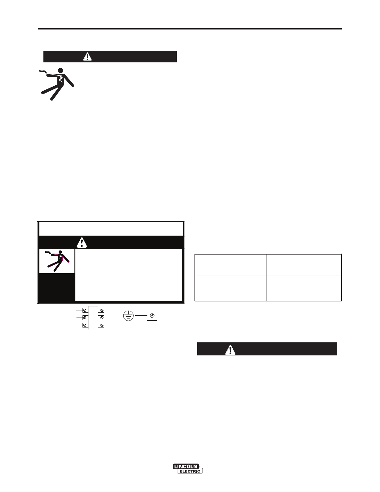
Connect L1, L2, L3 and ground according to the Input
Supply Connection Diagram decal located on the
inside of the input access door or refer to Figure A.1
below.
INPUT FUSE AND SUPPLY WIRE
CONSIDERATIONS
Refer to the Technical Specifications at the beginning
of this Installation section for recommended fuse and
wire sizes. Fuse the input circuit with the
recommended super lag fuse or delay type breakers
(also called “inverse time” or “thermal/magnetic” circuit
breakers). Choose an input and grounding wire size
according to local or national electrical codes. Using
fuses or circuit breakers smaller than recommended
may result in “nuisance” shut-offs from welder inrush
currents, even if the machine is not being used at high
currents.
ELECTRODE AND WORK CABLE
CONNECTIONS
Connect a work lead of sufficient size and length (Per
Table A.1) between the proper output terminal on the
power source and the work. Be sure the connection to
the work makes tight metal-to-metal electrical contact.
To avoid interference problems with other equipment
and to achieve the best possible operation, route all
cables directly to the work and wire feeder. Avoid
excessive lengths and do not coil excess cable.
Minimum work and electrode cable sizes are as follows:
TABLE A.1
Current MINIMUM COPPER
(60% Duty Cycle) WORK CABLE SIZE AWG
Up To-100 Ft. Length (30 m)
400 Amps 2/0 (67 mm2)
500 Amps 3/0 (85 mm2)
600 Amps 3/0 (85 mm2)
NOTE: K1796 coaxial welding cable is recommended
to reduce the cable inductance in long cable lengths.
This is especially important when Pulse welding up to
350 amps.
When using inverter type power sources like the
Power Waves®, use the largest welding (electrode
and work) cables that are practical. At least 2/0 (67
mm2) copper wire - even if the average output
current would not normally require it. When
pulsing, the pulse current can reach very high
levels. Voltage drops can become excessive,
leading to poor welding characteristics, if
undersized welding cables are used.
------------------------------------------------------------------------
WARNING
FIGURE A.1 - CONNECTION DIAGRAM ON
CONNECTION/INPUT ACCESS DOOR
CAUTION
W / L3
V / L2
U / L1
use or service this equipment.
Do not touch electrically live parts.
removed.
Only qualified persons should install,
Do not operate with covers
inspecting or servicing machine.
Disconnect input power before
.
.
.
.
CR1
WARNING
ELECTRIC
SHOCK
CAN KILL
INPUT SUPPLY CONNECTION DIAGRAM
Page 11
A-4
INSTALLATION
POWER WAVE®455M
A-4
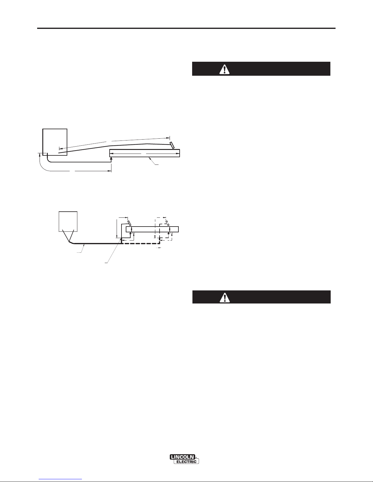
CABLE INDUCTANCE, AND ITS EFFECTS
ON PULSE WELDING
For Pulse Welding processes, cable inductance will
c
ause the welding performance to degrade. For the
total welding loop length less than
50 ft.(15.24m),
traditional welding cables may be used without any
effects on welding performance. For the total welding
l
oop length greater than
50 ft.(1
5.24m), the K1796
Coaxial Welding Cables are recommended. The
welding loop length is defined as the total of electrode
cable length (A) + work cable length (B) + work length
(C) (See Figure A.3).
For long work piece lengths, a sliding ground should
be considered to keep the total welding loop length
less than
50 ft.(15.24m). (See Figure A.4.)
Output connections on some Power Waves®are made
via 1/2-13 threaded output studs located beneath the
spring loaded output cover at the bottom of the case
front.
Most welding applications run with the electrode being
positive (+). For those applications, connect the
electrode cable between the wire feeder and the
positive (+) output stud on the power source (located
beneath the spring loaded output cover near the
bottom of the case front). Connect the other end of the
electrode cable to the wire drive feed plate. The
electrode cable lug must be against the feed plate. Be
sure the connection to the feed plate makes tight
metal-to-metal electrical contact. The electrode cable
should be sized according to the specifications given
in the work cable connections section. Connect a work
lead from the negative (-) power source output stud to
the work piece. The work piece connection must be
firm and secure, especially if pulse welding is planned.
For additional Safety information regarding the
electrode and work cable set-up, See the standard
"SAFETY INFORMATION" located in the front of the
Instruction Manuals.
Excessive voltage drops caused by poor work
piece connections often result in unsatisfactory
welding performance.
------------------------------------------------------------------------
NEGATIVE ELECTRODE POLARITY
When negative electrode polarity is required, such as
in some Innershield applications, switch the output
connections at the power source (electrode cable to
the negative (-) stud, and work cable to the
positive (+) stud).
When operating with electrode polarity negative the
"Electrode Sense Polarity" DIP switch must be set to
the "Negative" position on the Wire Drive Feed Head
PC Board. The default setting of the switch is positive
electrode polarity. Consult the Power Feed®instruction
manual for further details.
VOLTAGE SENSING
The best arc performance occurs when the Power
Waves®have accurate data about the arc conditions.
Depending upon the process, inductance within the
electrode and work lead cables can influence the
apparent voltage at the studs of the welder. Voltage
sense leads improve the accuracy of the arc
conditions and can have a dramatic effect on
performance. Sense Lead Kits (K940-10, -25 or -50)
are available for this purpose.
If the voltage sensing is enabled but the sense
leads are missing, improperly connected, or if the
electrode polarity switch is improperly configured,
extremely high welding outputs may occur.
------------------------------------------------------------------------
The ELECTRODE sense lead (67) is built into the
control cable, and is automatically enabled for all semiautomatic processes. The WORK sense lead (21)
connects to the Power Wave®at the four pin connector
located underneath the output stud cover. By default
the WORK voltage is monitored at the output stud in
the POWER WAVE®455M. For more information on
the WORK sense lead (21), see "Work Voltage
Sensing” in the following paragraph.
All constant current processes sense the voltage at the
output studs of the POWER WAVE®455M by default.
CAUTION
CAUTION
B
A
C
FIGURE A.3
POWER
WAVE
WORK
A
C
B
POWER
WAVE
F
IGURE A.4
K1796 COAXIAL CABLE
MEASURE FROM END
OF OUTER JACKET OF
CABLE
C
A
B
WORK
SLIDING
WORK
FIGURE A.4
Page 12
A-5
INSTALLATION
POWER WAVE®455M
A-5
Electrode Voltage Sensing
Enabling or disabling electrode voltage sensing is
automatically configured through software. The 67
electrode sense lead is internal to the cable to the
wire feeder and always connected when a wire feeder
is present.
Important: The electrode polarity must be
configured at the feed head for all semi-automatic
processes. Failure to do so may result in
extremely high welding outputs.
------------------------------------------------------------------------
POWER WAVE®TO SEMIAUTOMATIC POWER FEED®WIRE
FEEDER INTERCONNECTIONS
The POWER WAVE®455M and semi-automatic POWER
FEED
®
family communicate via a 5 conductor control
cable (K1543). The control cable consists of two power
leads, one twisted pair for digital communication, and
one lead for voltage sensing. The cables are designed to
be connected end to end for ease of extension. The
output receptacle on the POWER WAVE
®
455M is
located beneath the spring loaded output cover at the
bottom of the case front. The input receptacle on the
Power Feed
®
is typically located at the back of the
feeder, or on the bottom of the user interface.
For convenience sake, the electrode and control cables
can be routed behind the left or right strain reliefs (under
the spring loaded output cover), and along the channels
formed into the base of the Power Wave
®
, out the back of
the channels, and then to the wire feeder.
Due to the flexibility of the platform the configuration may
vary. The following is a general description of the
system.
SYSTEM DESCRIPTION
The POWER WAVE®455M and Power Feed®M family
of products utilize a digital communication system called
ArcLink. Simply put, ArcLink allows large amounts of
information to be passed at very high speeds between
components (nodes) in the system. The system
requires only two wires for communication, and because
of its bus-like structure, the components may be
connected to the network in any order, thus simplifying
the system set-up.
Each "system" must contain only one power source.
The number of wire feeders is determined by the type
of wire feeder. Refer to the wire feeder instruction
manual for details
Enable the voltage sense leads as follows:
TABLE A.2
Process Electrode Voltage Work Voltage
Sensing 67 lead * Sensing 21 lead
GMAW 67 lead required 21 lead optional
G
MAW-P67 lead required 21 lead optional
FCAW 67 lead required 21 lead optional
GTAW
Voltage sense at studs Voltage sense at studs
GMAW
Voltage sense at studs Voltage sense at studs
S
AW 67 lead required 21 lead optional
CAC
Voltage sense at studs Voltage sense at studs
* The electrode voltage 67 sense lead is integral to
the control cable to the wire feeder.
Work Voltage Sensing
The standard POWER WAVE
®
455M’s default to the
work stud (work sense lead disabled)
For processes requiring work voltage sensing,
connect the (21) work voltage sense lead (K940) from
the Power Wave®work sense lead receptacle to the
work piece. Attach the sense lead to the work piece
as close to the weld as practical, but not in the return
current path. Enable the work voltage sensing in the
Power Wave®as follows:
• Do not touch electrically live
parts or electrodes with your
skin or wet clothing.
• Insulate yourself from the work
and ground.
• Always wear dry insulating gloves.
------------------------------------------------------------------------
1. Turn off power to the power source at the
disconnect switch.
2. Remove the front cover from the power source.
3. The control board is on the left side of
the power source. Locate the 8-position
DIP switch and look for switch 8 of the
DIP switch.
4. Using a pencil or other small object,
slide the switch right to the OFF
position if the work sense lead is NOT
connected. Conversely, slide the switch
to the ON position if the work sense
lead is present.
5. Replace the cover and screws. The PC board will
“read” the switch at power up, and configure the
work voltage sense lead appropriately.
O
N
1 2 3 4 5 6 7 8
CAUTION
WARNING
Page 13
A-6
INSTALLATION
POWER WAVE®455M
A-6
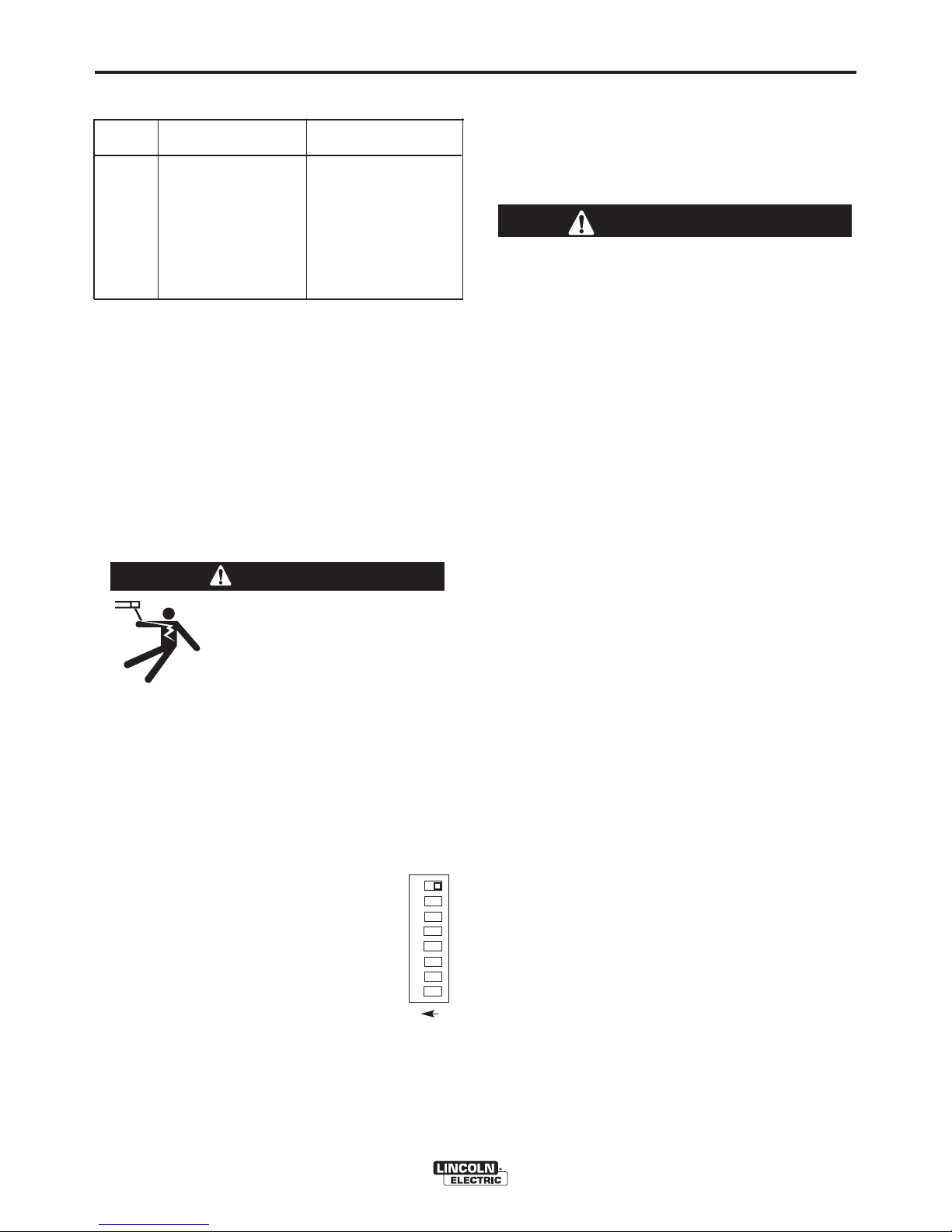
CONFIGURING THE SYSTEM
The power source will “Auto Map” the system
eliminating most of the need to set DIP switches to
configure the system.
I
f a system can not be “Auto Mapped” then the status
light on the power source will blink green fast and the
w
elder output will be disabled. If a system is not
“Auto-mappable”, then consult the instruction manual
for the accessory being used for configuration
information about DIP switch settings, or consult your
l
ocal Lincoln sales representative.
POWER WAVE
®
4
55M
ROBOT
PLC CONTROLLER
ANALOG INTERFACE
etc.
POWER WAVE®455M
POWER WAVE
®
455M
P
OWER WAVE
®
455M
FEED HEAD
SINGLE HEAD FEEDER DUAL HEAD FEEDER
SINGLE HEAD BOOM FEEDER
FH 1
PF-10R
SINGLE HEAD BOOM FEEDER
UP TO 4 FEEDERS
ALLOWED
UP TO 4 FEED HEADS
ALLOWED
WIRE
DRIVE
MODULE
Page 14
A-7
INSTALLATION
POWER WAVE®455M
A-7
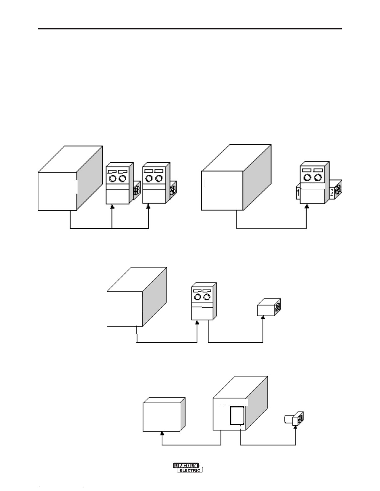
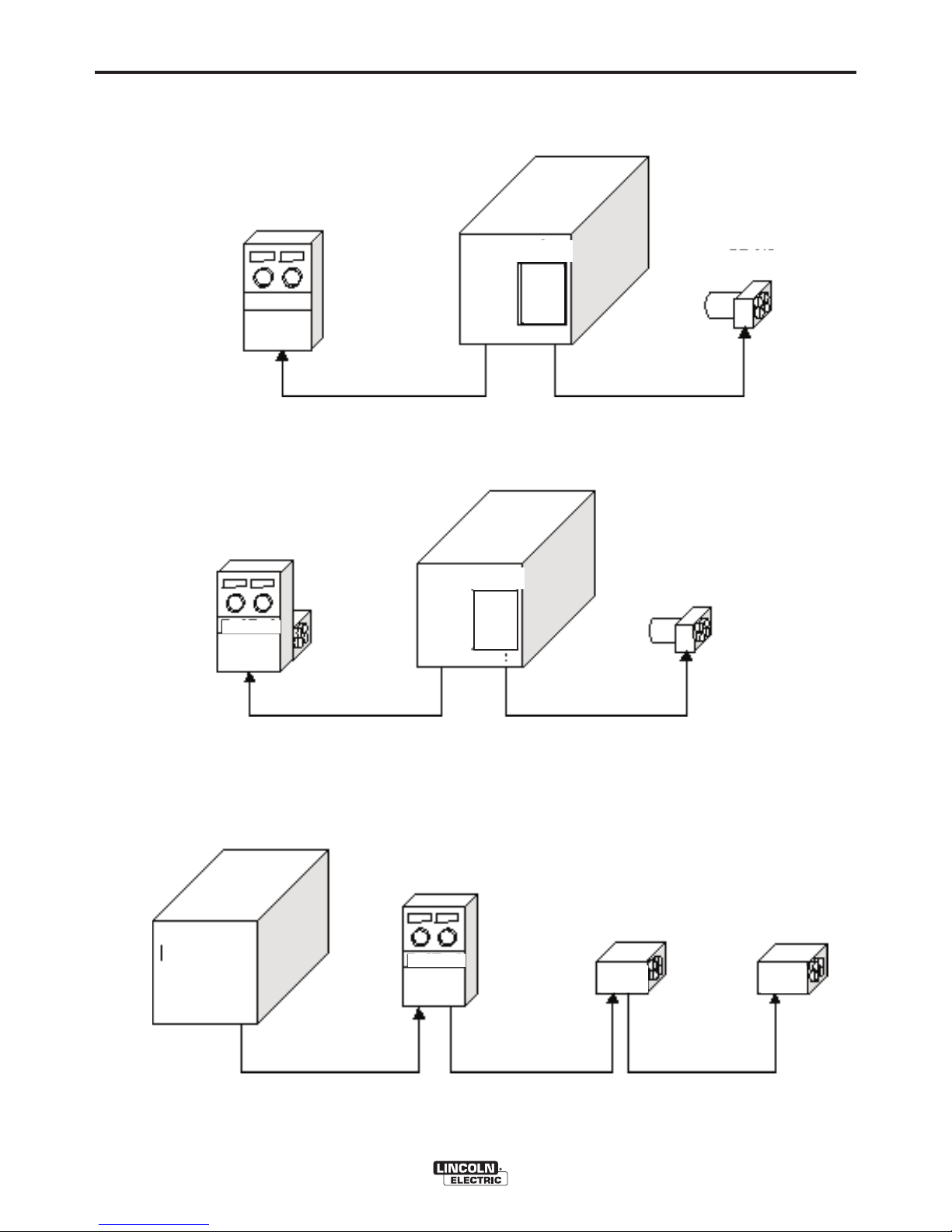
In this case the individual feed heads need to be assigned to the dual head control and the PW455 auto
mapping disabled and the Equipment Groups set on (See Figure A.6). (See the Feeder documentation for
information on setting the feeder DIP switches)
System that is NOT "Auto Mappable"
POWER WAVE®455M
POWER WAVE®455M
POWER WAVE
®
455M
D
UAL HEAD
DUAL HEAD
ALTERNATE HARD AUTOMATIC APPLICATION
(using a UI, WD Module, and PF-10R)
COMBINATION HARD AUTOMATION APPLICATION
(w/ Semi-Auto, WD Module, and PF-10R)
DUAL HEAD BOOM FEEDER
(using two single heads)
PF-10R
FH-1
FH-2
PF-10R
WIRE
DRIVE
M
ODULE
(FH1)
WIRE
D
RIVE
M
ODULE
(FH1)
Page 15
A-8
INSTALLATION
POWER WAVE®455M
A-8
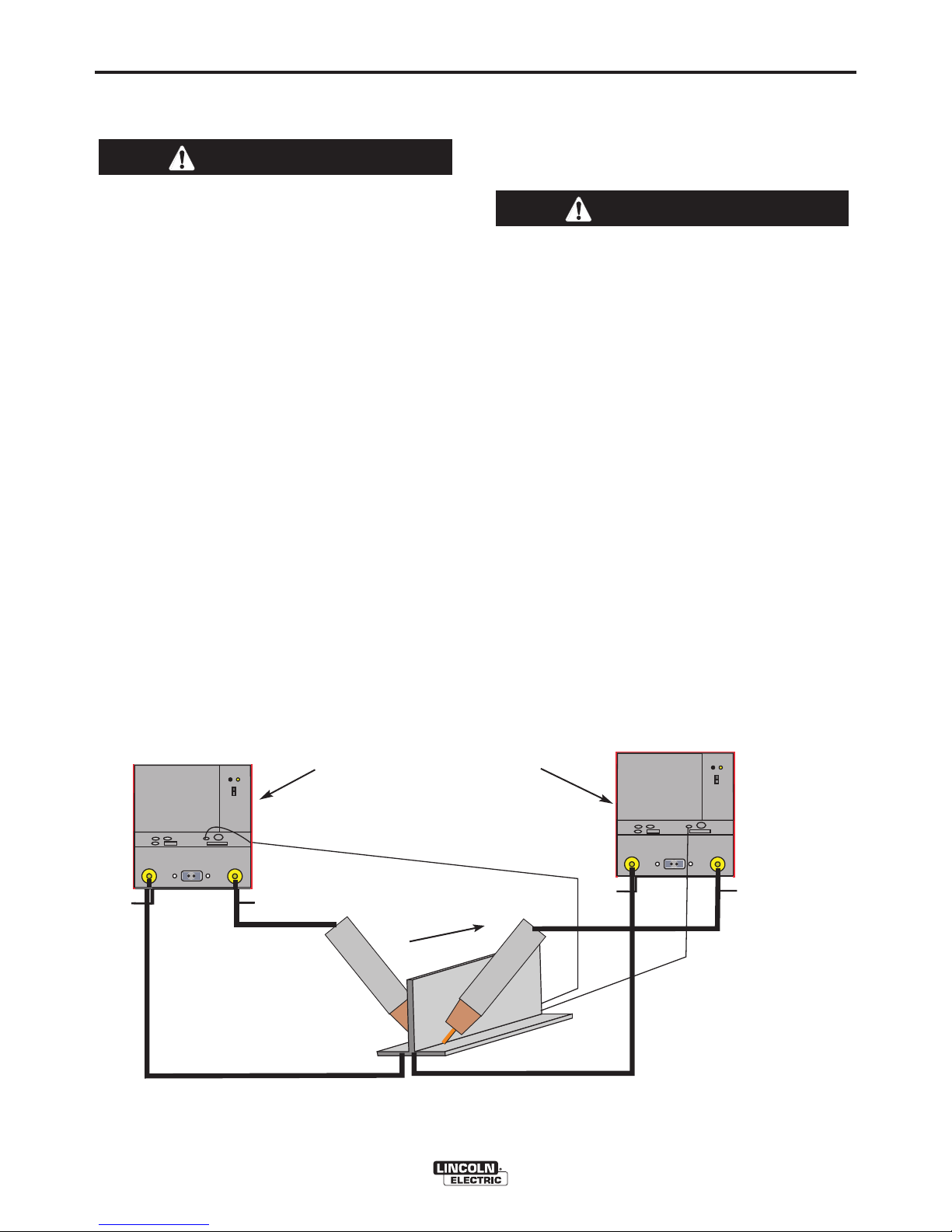
WELDING WITH MULTIPLE POWER
WAVES
®
Special care must be taken when more than one
P
ower Wave
®
i
s welding simultaneously on a
single part. Arc blow and arc interference may
occur or be magnified.
------------------------------------------------------------------------
Each power source requires a work lead from the
work stud to the welding fixture. Do not combine all of
the work leads into one lead. The welding travel
directions should be in the direction moving away from
the work lead as shown below. Connect all of the work
sense leads from each power source to the work
piece at the end of the weld.
For the best results when pulse welding, set the wire
size and wire feed speed the same for all the Power
Waves®. When these parameters are identical, the
pulsing frequency will be the same, helping to stabilize
the arcs.
Every welding gun requires a separate shielding gas
re gulator for prop er flow rate an d s hieldin g gas
coverage.
Do not attempt to supply shielding gas for two or more
guns from only one regulator.
If an anti-spatter system is in use then each gun must
have its own anti-spatter system. (See Figure A.2)
FIGURE A.2
-
+
POWERWAVE
Connect All Work
Sense Leads at the End
of the Joint
Connect All Welding
Work Leads at the
Beginning of the Joint
Travel
Direction
-
+
POWER WAVE®
-
+
POWERWAVE
-
+
POWER WAVE®
TWO POWER WAVES
®
CONTROL CABLE SPECIFICATIONS
I
t is recommended that genuine Lincoln control cables
be used at all times. Lincoln cables are specifically
designed for the communication and power needs of
the Power Wave
®
/ Power Feed®system.
The use of non-standard cables, especially in
lengths greater than 25 ft.(7.62), can lead to
communication problems (system shutdowns),
poor motor acceleration (poor arc starting) and
low wire driving force (wire feeding problems).
------------------------------------------------------------------------
The K1543 series of control cables can be connected
end to end for ease of extension. Do not exceed more
than 100 feet (30.5 m) total control cable length.
CAUTION
CAUTION
Page 16
A-9
INSTALLATION
POWER WAVE®455M
A-9
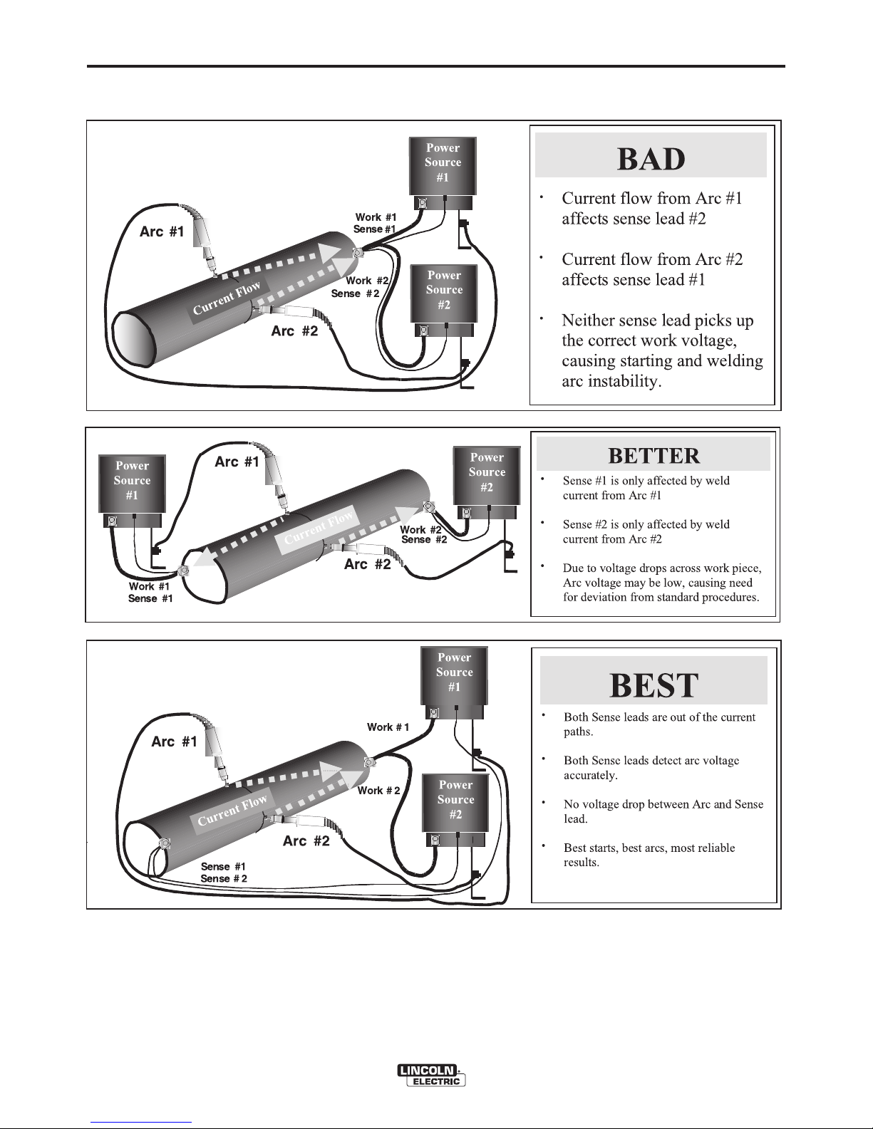
MULTIPLE ARC UNSYNCHRONIZED SENSE LEAD AND WORK LEAD PLACEMENT GUIDELINES
Page 17
A-10
INSTALLATION
POWER WAVE®455M
A-10
I / O RECEPTACLE SPECIFICATIONS
TABLE A.3
WIRE FEEDER RECEPTACLE S1
PIN LEAD# FUNCTION
A
53 Communication Bus L
B 54 Communication Bus H
C 67A Electrode Voltage Sense
D 52 0vdc
E
51 +40vdc
TABLE A.4
VOLTAGE SENSE RECEPTACLE S2
PIN LEAD# FUNCTION
3 21A Work Voltage Sense
TABLE A.5
RS232 RECEPTACLE S3
PIN LEAD# FUNCTION
2 253 RS232 Receive
3 254 RS232 Transmit
4#S3 Pin5
5#S3 Pin4
6 # # S3 Pin20
20 # # S3 Pin6
7 251 RS232 Common
DIP SWITCH SETTINGS AND LOCATIONS
DIP switches on the P.C. Boards allow for custom
configuration of the Power Wave®. To access the DIP
switches:
• Turn off power at the disconnect switch.
• Remove the top four screws securing the front
access panel.
• Loosen, but do not completely remove, the bottom
two screws holding the access panel.
• Open the access panel, allowing the weight of the
panel to be carried by the bottom two screws. Make
sure to prevent the weight of the access panel from
hanging on the harness.
• Adjust the DIP switches as necessary.
• Replace the panel and screws, and restore power.
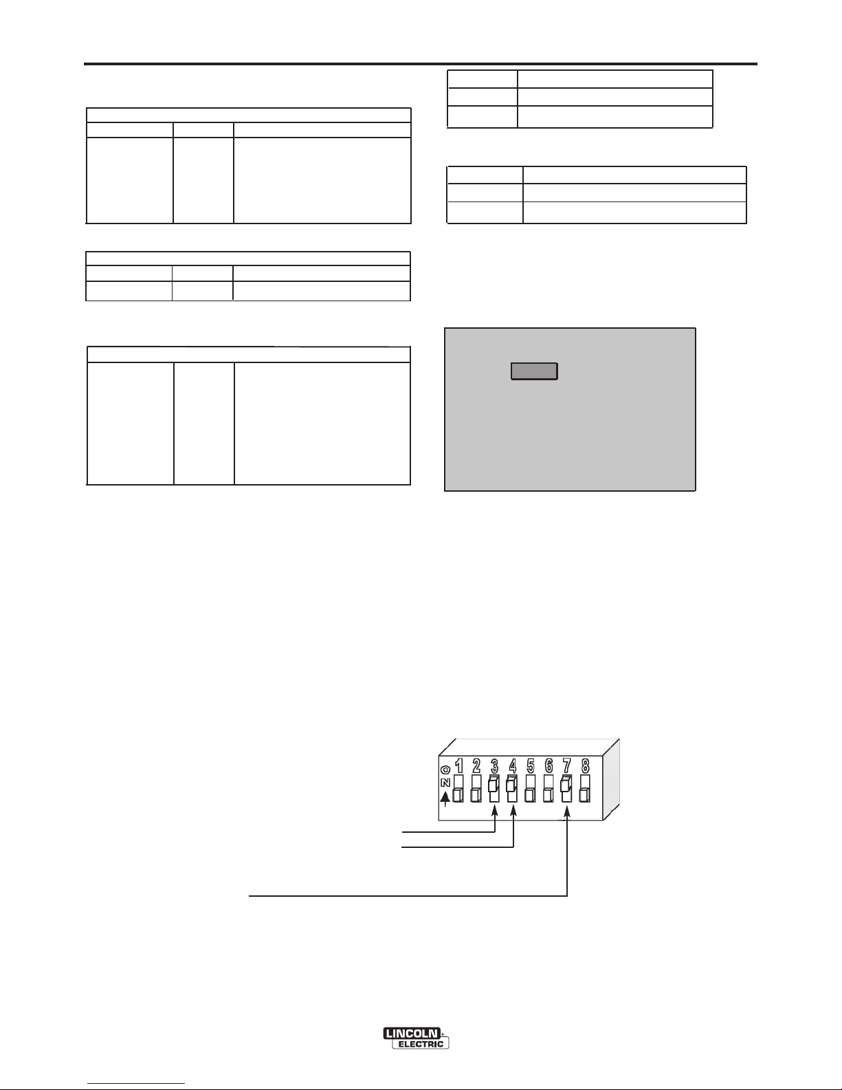
CONTROL BOARD DIP SWITCH:
switch 1 = reserved for future use
switch 2 = reserved for future use
switch 3 = equipment group 1 selcted (default=off)
switch 4 = equipment group 2 selcted (default=off)
switch 5 = reserved for future use
switch 6 = reserved for future use
switch 7 = auto mapping
switch 8 = work sense lead
(See Figure A.6 for Dual Head Boom Feeder)
switch 7
auto mapping
off(default) auto mapping enable
on auto mapping disabled
switch 8
work sense lead
*off(default) work sense lead not connected
on work sense lead connected
*
The POWER WAVE®455M does not come supplied with a
work sense lead.
WATER FLOW SENSOR
Water cooled guns can be damaged very quickly if
they are used even momentarily without water flowing.
A water flow sensor is recommended for those water
coolers that do not have an integral flow sensor.
Recommended practice is to install a water flow
sensor such as K1536-1 on the water return line of the
torch. When fully integrated into the welding system,
the sensor will prevent welding if no water flow is
present.
CONTROL BOARD (DIP Switch Location)
FIGURE A.5
FIGURE A.6
Page 18
B-1
OPERATION
B-1
POWER WAVE®455M
SAFETY PRECAUTIONS
Read this entire section of operating instructions
before operating the machine.
ELECTRIC SHOCK can kill.
• Do not touch electrically live parts or
electrodes with your skin or wet
clothing.
• Insulate yourself from the work and ground.
• Always wear dry insulating gloves.
• Do not operate with covers, panels or guards
removed or open.
FUMES AND GASES can be
dangerous.
• Keep your head out of fumes.
• Use ventilation or exhaust to remove
fumes from breathing zone.
WELDING SPARKS can cause fire
or explosion.
• Keep flammable material away.
• Do not weld on containers that have
held combustibles.
ARC RAYS can burn.
• Wear eye, ear, and body protection.
Observe additional guidelines detailed in the
beginning of this manual.
WARNING
Page 19

B-2
OPERATION
B-2
POWER WAVE®455M
INPUT POWER
ON
OFF
HIGH TEMPERATURE
MACHINE STATUS
CIRCUIT BREAKER
WIRE FEEDER
POSITIVE OUTPUT
NEGATIVE OUTPUT
3 PHASE INVERTER
INPUT POWER
THREE PHASE
DIRECT CURRENT
GMAW
FCAW
GTAW
OPEN CIRCUIT
VOLTAGE
INPUT VOLTAGE
OUTPUT VOLTAGE
INPUT CURRENT
OUTPUT CURRENT
PROTECTIVE
GROUND
WARNING OR
CAUTION
GRAPHIC SYMBOLS THAT APPEAR ON
THIS MACHINE OR IN THIS MANUAL
U
0
U
1
U
2
I
1
I
2
SMAW
Page 20

B-3
OPERATION
B-3
POWER WAVE®455M
DEFINITION OF WELDING TERMS
NON-SYNERGIC WELDINGMODES
• A Non-synergic welding mode requires all welding
p
rocess variables to be set by the operator.
SYNERGIC WELDINGMODES
• A Synergic welding mode offers the simplicity of
single knob control. The machine will select the
correct voltage and amperage based on the wire
feed speed (WFS) set by the operator.
455M
•455 Modular
WFS
• Wire Feed Speed
CC
• Constant Current
CV
• Constant Voltage
GMAW
• Gas Metal Arc welding
GMAW-P
• Gas Metal Arc welding-(Pulse Arc)
GMAW-S
• Gas Metal Arc welding-(Short Circuiting Arc)
GTAW
• Gas Tungsten Arc welding
GTAW-P
• Gas Tungsten Arc welding-(Pulse Arc)
PAW
• Plasma Arc welding
SMAW
•
Shielded Metal Arc welding
SW
• Stud Arc Welding
SAW
• Submerged Arc Welding
S
AW-S
• Submerged Arc Welding-(Series)
FCAW
• Flux Core Arc Welding
CAC
• Carbon Arc Cutting
Page 21

DeviceNet Interface Module
T
his module can be used for DeviceNet capability.
It has a 5 pin sealed mini connector per ANSI
B93.55M-1981.
EtherNet/DeviceNet Module
This module includes the DeviceNet and EtherNet
c
apability. The DeviceNet uses a 5 pin sealed mini
connector per ANSI B93.55M-1981. The EtherNet
uses a RJ5 connector.
RECOMMENDED EQUIPMENT
POWER WAVE®455M – Semi-Automatic Operation
Semi Automatic Power Waves®can only be used with
ArcLink compatible Power Feed®semi-automatic wire
feeders and modules. In addition, the Power Feed
®
semi-automatic wire feeders may require optional
equipment to access certain weld modes in the Power
Wave®. Other models of Lincoln feeders, or any
models of non-Lincoln wire feeders, cannot be used.
All welding programs and procedures are selected
through the Power Feed®M semi-automatic user
interface
REQUIRED EQUIPMENT
Any ArcLink compatible semi-automatic wire feeding
equipment. Specifically, the semi-automatic Power
Feed®M family.
LIMITATIONS
• The Power Waves®are not to be used in outdoor
environments.
------------------------------------------------------------------------
• Only ArcLink compatible Power Feed®semi-
automatic wire feeders and users interfaces may be
used. Other Lincoln wire feeders or non-Lincoln wire
feeders cannot be used.
• POWER WAVE®455M Output Limitations
The POWER WAVE®455M will support maximum
average output current of 570 Amps (@ 60% duty
cycle) on the standard Power Wave stud.
DUTY CYCLE AND TIME PERIOD
The Power Feed®wire feeders are capable of welding
at a 100% duty cycle (continuous welding). The power
source will be the limiting factor in determining system
duty cycle capability. Note that the duty cycle is based
upon a ten minute period. A 60% duty cycle
represents 6 minutes of welding and 4 minutes of
idling in a ten minute period.
B-4
OPERATION
B-4
GENERAL DESCRIPTION
The Power Wave®semi-automatic power source is
d
esigned to be a part of a modular, multi-process
welding system. Depending on configuration, it can
s
upport constant current, constant voltage, and pulse
welding modes.
The Power Wave
®
power source is designed to be
u
sed with the semi automatic family of Power Feed
®
wire feeders, operating as a system. Each component
in the system has special circuitry to "talk with" the
other system components, so each component (power
source, wire feeder, user interface) knows what the
other is doing at all times. These components
communicate with ArcLink
The POWER WAVE®455M is a high performance,
digitally controlled inverter welding power source
capable of complex, high-speed waveform control.
Properly equipped, it can support the GMAW,
GMAW-P, FCAW, SMAW, GTAW, and CAC
processes. It carries an output rating of either 450
amps, 38 volts; or 400 amps, 36 volts (both at 100%
duty cycle), depending on input voltage and
frequency.
RECOMMENDED PROCESSES AND
EQUIPMENT
RECOMMENDED PROCESSES
The POWER WAVE®455M can be set up in a number
of configurations, some requiring optional equipment
or welding programs. Each machine is factory preprogrammed with multiple welding procedures, typically
including GMAW, GMAW-P, FCAW, GTAW, and CAC
for a variety of materials, including mild steel,
stainless steel, cored wires, and aluminum.
The POWER WAVE®455M is recommended for semiautomatic welding with ArcLink compatible equipment
like the Power Feed®M series of feeders. The
POWER WAVE®455M can have a number of
modules installed that allow the machine to be used in
Robotic and hard automation applications.
Wire Drive Interface Module
For Robotic platforms the Wire Drive Control Module
is required to drive the PF-10R wire drive. This
module can be field installed for robotic applications.
The Wire Drive Control Module is also equipped with
a terminal strip for making simple input signal
connections. It can be used to externally control the
basic wire drive function. It is divided into three
groups: Trigger group, Cold Inch group, and
Shutdown group.
POWER WAVE®455M
WARNING
Page 22

B-5
OPERATION
POWER WAVE®455M
B-5
CASE FRONT CONTROLS
A
ll operator controls and adjustments are located on
the case front of the Power Wave
®
. (See Figure B.1)
1. POWER SWITCH: Controls input power to the
Power Wave®.
2
. STATUS LIGHT: A two color light that indicates
system errors. Normal operation is a steady green
light. Error conditions are indicated, per table B.1.
NOTE: The POWER WAVE
®
455M status light will
flash green, and sometimes red and green, for up to
one minute when the machine is first turned on. This
is a normal situation as the machine goes through a
self test at power up.
TABLE B.1
Light
Condition
Steady Green
Blinking
Green
A l t e r na t in g
Gre e n and
Red
Steady Red
Blinking Red
Meaning
System OK. Power source communicating
normally with wire feeder and its components.
Occurs during a reset, and indicates the
POWER WAVE
®
455M is mapping
(identifying) each component in the system.
Normal for first 1-10 seconds after power is
turned on, or if the system configuration is
changed during operation
Non-recoverable system fault. If the PS
Status light is flashing any combination of
red and green, errors are present in the
POWER WAVE
®
455M. Read the error
code before the machine is turned off.
Error Code interpretation through the Status
light is detailed in the Service Manual.
Individual code digits are flashed in red with
a long pause between digits. If more than
one code is present, the codes will be
separated by a green light.
To clear the error, turn power source off,
and back on to reset. See Troubleshooting
Section.
Non recoverable hardware fault. Generally
indicates nothing is connected to the
POWER WAVE
®
455M wire feeder
receptacle. See Trouble Shooting Section.
Not applicable.
5.
15 AMP AUXILIARY POWER CIRCUIT BREAKER:
Protects 220 volt AC case front receptacle
auxiliary supply.
6. LEAD CONNECTOR S2 (SENSE LEAD)
7. DIAGNOSTIC CONNECTOR (RS-232)
8. WIRE FEEDER RECEPTACLE (S1 5-PIN)
9. NEGATIVE STUD
10. POSITIVE STUD
11. AUXILIARY OUTPUT
12. 5-PIN DEVICENET CONNECTOR (OPTIONAL)
13. ROBOTIC WIRE FEEDER RECEPTACLE
(OPTIONAL)
14. I/O CONNECTOR (OPTIONAL)
15. ETHERNET CONNECTOR (OPTIONAL)
FIGURE B.1
3. HIGH TEMPERATURE LIGHT (thermal overload):
A yellow light that comes on when an over
temperature situation occurs. Output is disabled
and the fan continues to run, until the machine
cools down. When cool, the light goes out and
output is enabled.
4. 10 AMP WIRE FEEDER CIRCUIT BREAKER:
Protects 40 volt DC wire feeder power supply.
CASE FRONT LAYOUT
POWER WAVE
®
455M (CE)
2
3
1
10
9
12
15
8
7
13
14
6
4
11
5
Page 23

B-6
OPERATION
B-6
NOMINAL PROCEDURES
The Power Wave®is designed to operate with 3/4"
electrode stick-out for CV and Pulse processes.
FRINGE PROCEDURES
Excessively short or long electrode stick-outs may
function only on a limited basis, if at all.
MAKING A WELD
The serviceability of a product or structure
utilizing the welding programs is and must be the
sole responsibility of the builder/user. Many
variables beyond the control of The Lincoln
Electric Company affect the results obtained in
applying these programs. These variables include,
but are not limited to, welding procedure, plate
chemistry and temperature, weldment design,
fabrication methods and service requirements.
The available range of a welding program may not
be suitable for all applications, and the build/user
is and must be solely responsible for welding
program selection.
------------------------------------------------------------------------
The steps for operating the Power Wave®will vary
depending upon the options installed in the user
interface (control box) of the welding system. The
flexibility of the Power Wave®system lets the user
customize operation for the best performance.
First, consider the desired welding process and the
part to be welded. Choose an electrode material,
diameter, shielding gas and process (GMAW,
GMAW-P, etc.)
Second, find the program in the welding software that
best matches the desired welding process. The
standard software shipped with the Power Waves
®
encompasses a wide range of common processes
and will meet most needs. If a special welding
program is desired, contact the local Lincoln Electric
sales representative.
To make a weld, the Power Wave
®
needs to know the
desired welding parameters. The Power Feed®(PF)
family of feeders communicate settings to the
Power Wave
®
through control cable connection. Arc
length, wire feed speed, arc control, etc. are all
communicated digitally via the control cable.
WELDING ADJUSTMENTS
All adjustments are made on the system component
known as the User Interface (Control Box), which
contains the switches, knobs, and digital displays
necessary to control both the Power Wave®and a
Power Feed®wire feeder. Typically, the Control Box is
s
upplied as part of the wire feeder. It can be mounted
directly on the wire feeder itself, the front of the power
source, or mounted separately, as might be done in a
welding boom installation.
Because the Control Box can be configured with many
different options, your system may not have all of the
following adjustments. Regardless of availability, all
controls are described below. For further information,
consult the Power Feed
®
wire feeder instruction
manual.
• WFS / AMPS:
In synergic welding modes (synergic CV, pulse
GMAW) WFS (wire feed speed) is the dominant
control parameter, controlling all other variables. The
user adjusts WFS according to factors such as weld
size, penetration requirements, heat input, etc. The
Power Wave®then uses the WFS setting to adjust its
output characteristics (output voltage, output current)
according to pre-programmed settings contained in
the POWER WAVE®455M. In non-synergic modes,
the WFS control behaves more like a conventional CV
power source where WFS and voltage are
independent adjustments. Therefore to maintain the
arc characteristics, the operator must adjust the
voltage to compensate for any changes made to the
WFS.
In constant current modes (stick, TIG) this control
adjusts the output current, in amps.
• VOLTS / TRIM:
In constant voltage modes (synergic CV, standard
CV) the control adjusts the welding voltage.
In pulse synergic welding modes (pulse GMAW only)
the user can change the Trim setting to adjust the arc
length. It is adjustable from 0.500 to 1.500. A Trim
setting of 1.000 is a good starting point for most
conditions.
POWER WAVE®455M
WARNING
Page 24

CURRENT WAVE FORM (CV)
B-7
OPERATION
B-7
•
WELDING MODE
May be selected by name (CV/MIG, CC/Stick Crisp,
G
ouge, etc.) or by a mode number (10, 24, 71, etc.)
depending on the Control Box options. Selecting a
welding mode determines the output characteristics of
the Power Wave
®
power source. For a more complete
d
escription of the welding modes available in the
Power Wave
®
, see the explanation below.
• ARC CONTROL
Also known as Inductance or Wave Control. Allows
operator to vary the arc characteristics from "soft" to
"harsh" in all weld modes. It is adjustable from -10.0 to
+10.0, with a nominal setting of 00.0 (The nominal
setting of 00.0 may be displayed as OFF on some
Power Feed®wire feeder control panels). See the
Welding Mode descriptions, below, for detailed explanations of how the Arc Control affects each mode.
CONSTANT VOLTAGE WELDING
Synergic CV:
For each wire feed speed, a corresponding voltage is
preprogrammed into the machine through special
software at the factory. The nominal preprogrammed
voltage is the best average voltage for a given wire
feed speed, but may be adjusted to preference. When
the wire feed speed changes, the Power Wave
®
automatically adjusts the voltage level correspondingly to maintain similar arc characteristics
throughout the WFS range.
N
on Synergic CV:
This type of CV mode behaves more like a
c
onventional CV power source. Voltage and WFS are
independent adjustments. Therefore to maintain the
arc characteristics, the operator must adjust the
voltage to compensate for any changes made to the
W
FS.
All CV Modes:
Arc Control, often referred to as wave control, adjusts
the inductance of the wave shape. The wave control
adjustment is similar to the "pinch" function in that it is
inversely proportional to inductance. Therefore,
increasing wave control greater than 0.0 results in a
harsher, colder arc while decreasing the wave control
to less than 0.0 provides a softer, hotter arc.
(See Figure B.2)
POWER WAVE®455M
FIGURE B.2
Current
Time
W
A
V
E
C
O
N
T
R
O
L
+1
0
.
0
W
AV
E
C
ON
T
R
OL
-
1
0
.
0
W
AV
E
C
O
N
T
R
O
L
0
.
0
0
Page 25

B-8
OPERATION
B-8
PULSE WELDING
Pulse welding procedures are set by controlling an
overall "arc length" variable. When pulse welding, the
arc voltage is highly dependent upon the waveform.
The peak current, back ground current, rise time, fall
time and pulse frequency all affect the voltage. The
exact voltage for a given wire feed speed can only be
p
redicted when all the pulsing waveform parameters
are known. Using a preset voltage becomes
impractical, and instead the arc length is set by
adjusting "trim".
Trim adjusts the arc length and ranges from 0.50 to
1.50, with a nominal value of 1.00. Trim values greater
than 1.00 increase the arc length, while values less
than 1.00 decrease the arc length.
Most pulse welding programs are synergic. As the
wire feed speed is adjusted, the Power Wave
®
will
automatically recalculate the waveform parameters to
maintain similar arc properties.
POWER WAVE®455M
Current
WAVE CONTROL -10.0
WAVE CONTROL 0.0
WAVE CONTROL +10.0
Time
FIGURE B.3
CURRENT WAVE FORM (PULSE)
The Power Wave®utilizes "adaptive control" to
c
ompensate for changes in electrical stick-out while
welding. (Electrical stick-out is the distance from the
contact tip to the work piece.) The Power Wave
®
waveforms are optimized for a 0.75" (19mm) stick-out.
The adaptive behavior supports a range of stickouts
from 0.50" (13mm) to 1.25" (32mm). At very low or
high wire feed speeds, the adaptive range may be
less due to reaching physical limitations of the welding
process.
Arc Control, often referred to as wave control, in pulse
programs usually adjusts the focus or shape of the
arc. Wave control values greater than 0.0 increase the
pulse frequency while decreasing the background
current, resulting in a tight, stiff arc best for high speed
sheet metal welding. Wave control values less than
0.0 decrease the pulse frequency while increasing the
background current, for a soft arc good for out-ofposition welding.
(See Figure B.3)
Page 26

C-1
ACCESSORIES
C-1
OPTIONAL EQUIPMENT
FACTORY INSTALLED
None Available
FIELD INSTALLED
Work Voltage Sense Lead Kit, K940
Dual Cylinder Undercarriage, K1570-1
Gas Guard Regulator, K659-1
Coaxial welding Cable, K1796
Cool Arc 40 K1813-1 (115VAC)
Water Flow Sensor, K1536-1
Wire Drive Interface Module, K2205-1
DeviceNet interface Module, K2206-1
COMPATIBLE LINCOLN EQUIPMENT
Any Arc-Link compatible semi-automatic wire feeding
equipment. Specifically, the semi-automatic Power
Feed®M family. If the wire drive interface module is
installed the machine is compatible with the Power
Feed®10R wire feeder.
POWER WAVE®455M
Page 27

D
-1
MAINTENANCE
D
-1
POWER WAVE®455M
SAFETY PRECAUTIONS
ELECTRIC SHOCK can kill.
•
Only Qualified personnel should
perform this maintenance.
• Turn the input power OFF at the
disconnect switch or fuse box
before working on this equipment.
• Do not touch electrically hot parts.
ROUTINE MAINTENANCE
Routine maintenance consists of periodically blowing
out the machine, using a low pressure airstream, to
remove accumulated dust and dirt from the intake and
outlet louvers, and the cooling channels in the
machine.
PERIODIC MAINTENANCE
Calibration of the POWER WAVE®455M is critical to
its operation. Generally speaking the calibration will
not need adjustment. However, neglected or
improperly calibrated machines may not yield satisfactory weld performance. To ensure optimal
performance, the calibration of output Voltage and
Current should be checked yearly.
CALIBRATION SPECIFICATION
Output Voltage and Current are calibrated at the
factory. Generally speaking the machine calibration
will not need adjustment. However, if the weld
performance changes, or the yearly calibration check
reveals a problem, contact the Lincoln Electric
Company for the calibration software utility.
The calibration procedure itself requires the use of a
grid, and certified actual meters for voltage and
current. The accuracy of the calibration will be directly
affected by the accuracy of the measuring equipment
you use. Detailed instructions are available with the
utility.
WARNING
Page 28

E-1
TROUBLESHOOTING
E-1
POWER WAVE®455M
If for any reason you do not understand the test procedures or are unable to perform the tests/repairs safely, contact your
Local Lincoln Authorized Field Service Facility for technical troubleshooting assistance before you proceed.
CAUTION
This Troubleshooting Guide is provided to help you
locate and repair possible machine malfunctions.
Simply follow the three-step procedure listed below.
Step 1. LOCATE PROBLEM (SYMPTOM).
Look under the column labeled “PROBLEM
(SYMPTOMS)”. This column describes possible
symptoms that the machine may exhibit. Find the
listing that best describes the symptom that the
machine is exhibiting.
Step 2. POSSIBLE CAUSE.
The second column labeled “POSSIBLE CAUSE” lists
the obvious external possibilities that may contribute
to the machine symptom.
Step 3. RECOMMENDED COURSE OF ACTION
This column provides a course of action for the
Possible Cause, generally it states to contact your
local Lincoln Authorized Field Service Facility.
If you do not understand or are unable to perform the
Recommended Course of Action safely, contact your
local Lincoln Authorized Field Service Facility.
HOW TO USE TROUBLESHOOTING GUIDE
Service and Repair should only be performed by Lincoln Electric Factory Trained Personnel.
Unauthorized repairs performed on this equipment may result in danger to the technician and
machine operator and will invalidate your factory warranty. For your safety and to avoid Electrical
Shock, please observe all safety notes and precautions detailed throughout this manual.
__________________________________________________________________________
WARNING
Page 29

E-2
TROUBLESHOOTING
E-2
POWER WAVE®455M
USING THE STATUS LED TO
TROUBLESHOOT SYSTEM PROBLEMS
The Power Wave®/ Power Feed®are best diagnosed
a
s a system. Each component (power source, user
interface, and feed head) has a status light, and when
a problem occurs it is important to note the condition
of each. In addition, errors displayed on the user
i
nterface in most cases indicate only that a problem
exists in the power source, not what the problem may
be. Therefore, prior to cycling power to the
system, check the power source status light for
error sequences as noted below. This is especially
important if the user interface displays "Err 006"
or "Err 100" .
Included in this section is information about the power
s
ource Status LED, and some basic troubleshooting
charts for both machine and weld performance.
The STATUS LIGHT is a two color light that indicates
s
ystem errors. Normal operation is a steady green
light. Error conditions are indicated in the following
chart.
N
OTE: The POWER WAVE
®
4
55M status light will
flash green, and sometimes red and green, for up to
one minute when the machine is first turned on. This
is a normal situation as the machine goes through a
self test at power up.
LIGHT CONDITION
Status LED is solid green (no blinking).
Status LED is blinking green.
Status LED is blinking red and green.
Status LED is solid red (no blinking).
Status LED is blinking red.
MEANING
1. System OK. Power source communicating normally
with wire feeder and its components.
2. Occurs during a reset, and indicates the POWER
WAVE®455M is mapping (identifying) each
component in the system. Normal for first 1-10
seconds after power is turned on, or if the system
configuration is changed during operation.
3. Non-recoverable system fault. If the PS Status light
is flashing any combination of red and green, errors
are present in the POWER WAVE®455M. Read the
error code before the machine is turned off.
Error Code interpretation through the Status light is
detailed in the Service Manual. Individual code digits
are flashed in red with a long pause between digits. If
more than one code is present, the codes will be
separated by a green light.
To clear the error, turn power source off, and back
on to reset.
Non recoverable hardware fault. Generally indicates
nothing is connected to the POWER WAVE®455M
wire feeder receptacle. See Trouble Shooting Section.
Not applicable.
Page 30

E-3
TROUBLESHOOTING
E-3
POWER WAVE®455M
Observe all Safety Guidelines detailed throughout this manual
If for any reason you do not understand the test procedures or are unable to perform the tests/repairs safely, contact your
Local Lincoln Authorized Field Service Facility for technical troubleshooting assistance before you proceed.
CAUTION
ERROR CODES FOR THE POWER WAVE
®
The following is a list of possible error codes that the POWER WAVE®455M can output via the status light (see
"Troubleshooting the Power Wave®/ Power Feed®System Using the Status LED." If connected to a PF-10/11
t
hese error codes will generally be accompanied by an "Err 006" or "Err 100" on the user interface display.
ERROR CODE
INDICATION
1
1
C
AN communication bus off.
P
robably due to excessive number of communication errors.
12 User Interface time out error. UI is no longer responding to the Power Source. The most likely cause is a fault/bad
connection in the communication leads or control cable.
21 Unprogrammed Weld Mode. Contact the Service Department for instructions on reloading the Welding Software.
22 Empty Weld Table. Contact the Service Department for instructions on reloading the Welding Software.
23 Weld Table checksum error. Contact the Service Department for instructions on reloading the Welding Software.
31 Primary overcurrent error. Excessive Primary current present. May be related to a short in the main transformer or
output rectifier.
32 Capacitor "A" under voltage
(Left side facing machine)
Low voltage on the main capacitors. May be caused by improper input configuration.
33 Capacitor "B" under voltage
(Right side facing machine)
When accompanied by an overvoltage error on the same side, it indicates no capacitor
voltage present on that side, and is usually the result of an open or short in the primary
side of the machine.
34 Capacitor "A" over voltage
(Left side facing machine)
Excess voltage on the main capacitors. May be caused by improper input configuration.
35 Capacitor "B" over voltage
(Right side facing machine)
When accompanied by an under voltage error on the same side, it indicates no capacitor
voltage present on that side, and is usually the result of an open or short in the primary
side of the machine.
36 Thermal error Indicates over temperature. Usually accompanied by Thermal LED. Check fan operation.
Be sure process does not exceed duty cycle limit of the machine.
37 Soft start error Capacitor precharge failed. Usually accompanied by codes 32-35.
41 Secondary overcurrent error The secondary (weld) current limit has been exceeded. When this occurs the machine
output will phase back to 100 amps, typically resulting in a condition referred to as
"noodle welding"
NOTE: The secondary limit is 570 amps for the standard stud, and 325 amps for all
single phase operation.
43 Capacitor delta error The maximum voltage difference between the main capacitors has been exceeded. May
be accompanied by errors 32-35.
49 Single phase error Indicates machine is running on single phase input power. Usually caused by the loss of
the middle leg (L2).
Other Error codes that contain three or four digits are defined as fatal errors. These codes
generally indicate internal errors on the PS Control Board. If cycling the input power on
the machine does not clear the error, try reloading the operating system. If this fails,
replace the control board.
Page 31

E-4
TROUBLESHOOTING
E-4
POWER WAVE®455M
Observe all Safety Guidelines detailed throughout this manual
CAUTION
If for any reason you do not understand the test procedures or are unable to perform the tests/repairs safely,
contact your local authorized Lincoln Electric Field Service Facility for technical assistance.
PROBLEMS
(SYMPTOMS)
POSSIBLE
CAUSE
RECOMMENDED
COURSE OF ACTION
OUTPUT PROBLEMS
Major physical or electrical damage
is evident when the sheet metal
covers are removed.
Input fuses keep blowing, or input
breaker keeps tripping.
Machine will not power up (no
lights, no fan, etc.)
Thermal LED is lit.
1. Contact your local authorized
Lincoln Electric Field Service
facility for technical assistance.
1
. Make certain that fuses or
breakers are properly sized.
See Installation section of this
manual for recommended
fuse and breaker sizes.
2. Welding procedure is drawing
too much output current, or
duty cycle is too high.
Reduce output current, duty
cycle, or both.
3. There is internal damage to
the power source. Contact an
authorized Lincoln Electric
Service facility.
1. Make certain that the Power
Switch (SW1) is in the “ON”
position.
2. Circuit breaker CB4 (in
reconnect area) may have
opened. Reset. Also, check
input voltage selection, below.
3. Input voltage selection made
improperly. Power down,
check input voltage reconnect
according to diagram on
reconnect cover.
1. Fan thermostat has opened.
Check for proper fan
operation. (Fan should run
whenever output power is on.)
Check for material blocking
intake or exhaust louvers, or
for excessive dirt clogging
cooling channels in machine.
2. Secondary rectifier or Choke
thermostat has opened. After
machine has cooled, reduce
load, duty cycle, or both.
Check for material blocking
intake or exhaust louvers.
3. DC Bus PC board thermostat
has opened check for
excessive load on 40VDC
supply.
If all recommended possible areas
of misadjustments have been
checked and the problem persists,
contact your local Lincoln
Authorized Field Service Facility.
Page 32

E-5
TROUBLESHOOTING
E-5
POWER WAVE®455M
O
bserve all Safety Guidelines detailed throughout this manual
CAUTION
If for any reason you do not understand the test procedures or are unable to perform the tests/repairs safely,
contact your local authorized Lincoln Electric Field Service Facility for technical assistance.
PROBLEMS
(SYMPTOMS)
POSSIBLE
CAUSE
RECOMMENDED
COURSE OF ACTION
OUTPUT PROBLEMS
Machine won’t weld, can’t get any
output. (CR1 will not pull in.)
Machine often “noodle welds”
(output is limited to approximately
100 amps) when running a
particular procedure, especially a
procedure with high WFS.
1. Input voltage is too low or too
high. Make certain that input
voltage is proper, according to
the Rating Plate located on the
rear of the machine.
2. If the Thermal LED is also lit,
see “Yellow Thermal LED is Lit”
section.
3. Primary current limit has been
exceeded. Possible short in
output circuit. Turn machine off.
Remove all loads from the
output of the machine. Turn
back on. If condition persists,
turn power off, and contact an
authorized Lincoln Electric Field
Service facility.
4
. This problem will normally be
accompanied by an error code.
Error codes are displayed as a
series of red and green flashes by
the status light. See
"Troubleshooting the Power
Wave®/ Power Feed®System
Using the Status LED" section of
this text.
1.Secondary current limit has been
exceeded, and the machine has
phased back to protect itself.
2. Adjust procedure or reduce load
to lower current draw from the
machine.
3. A single phase input (loss of L2)
will reduce the secondary
current limit from 570 Amps to
325 Amps.
If all recommended possible areas
of misadjustments have been
checked and the problem persists,
contact your local Lincoln
Authorized Field Service Facility.
Page 33

E-6
TROUBLESHOOTING
E-6
POWER WAVE®455M
O
bserve all Safety Guidelines detailed throughout this manual
CAUTION
If for any reason you do not understand the test procedures or are unable to perform the tests/repairs safely,
contact your local authorized Lincoln Electric Field Service Facility for technical assistance.
PROBLEMS
(SYMPTOMS)
POSSIBLE
CAUSE
RECOMMENDED
COURSE OF ACTION
OUTPUT PROBLEMS
Machine won’t produce full output.
Auxiliary receptacle is “dead” no
auxiliary voltage .
General degradation of the weld
performance
Excessively long and erratic arc.
1. Input voltage may be too low,
l
imiting output capability of the
power source. Make certain that
the input voltage is proper,
according to the Rating Plate
located on the rear of the
machine.
2. Input may be “single phased”.
Make certain the input voltage is
proper on all three Input lines.
3. Secondary current or voltage not
be properly calibrated. Check
values displayed on the Power
Feed 10/11 verses readings on
an external meter.
1. Circuit breaker CB2 (on case
front) may have opened. Reset.
2. Circuit breaker CB4 (in
reconnect area) may have
opened. Reset.
1.Check for feeding problems, bad
connections, excessive loops in
cabling, etc.
2. Verify weld mode is correct for
processes.
3. The power source may require
calibration.
4. Check the actual current
displayed on the Power Feed
®
10 vs. actual current measured
via external meter.
5. Check the actual voltage
displayed on the Power Feed
®
10 vs. actual voltage measured
via external meter.
6. Check the actual WFS displayed
on the Power Feed®10 vs.
actual WFS measured via
external meter.
1. Check for proper configuration
and implementation of voltage
sensing circuits.
If all recommended possible areas
of misadjustments have been
checked and the problem persists,
contact your local Lincoln
Authorized Field Service Facility.
Page 34
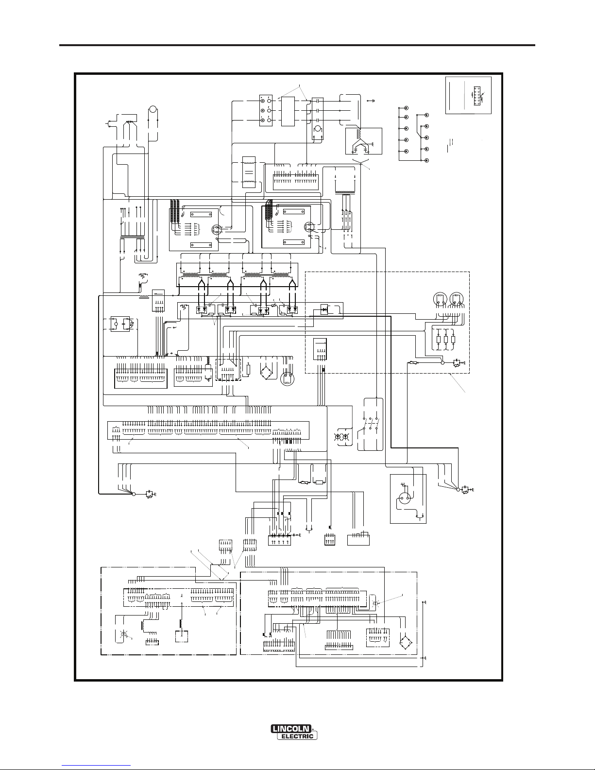
E-7
DIAGRAMS
E-7
POWER WAVE®455M
NOTE: This diagram is for reference only. It may not be accurate for all machines covered by this manual. The specific diagram for a particular code is pasted inside the
machine on one of the enclosure panels. If the diagram is illegible, write to the Service Department for a replacement. Give the equipment code number.
-
TO J9
202
WORK
202A
TO R1
TO TP6
S1
ARCLINK
RECEPTACLE
+
ELECTRODE
223
221
206A
R3
C8
TO D5
289D
R2
2
Ω
288C
288D
289E
288E
J1
4
5
R
3R33W
238
5
J10
TO
STATUS
LED
RECT
THERM
223
222
CHOPPER BOARD
SEC
(BOTTOM
LEFT)
POWER BD
RECTIFIER
AC
EMITTER
212
213
813
811
216
4
CONTROL BOARD
+
TO J61
CR1
X4
6
TO AUX #1
503
5
04
505
5
06
INPUT
20D
17
18
15
16
F1
F1
TO
CB1
J41
1
4R
J4
251
20
C
J47
TO
P90
P91
RECT
292
1
2
3
4
SEC
(TOP
LEFT)
6
U
L1B
V
L3
AC
3
TO
CR1
SW1
CB4
T2
L2
AC
2
H1D
T3
T1
T2
612
T3
NEG
1
2
3
4
+
4W
346
C3
AUX. #1
TO
4
3
D3
TO
CHOKE
THERM
D
CURRENT
TRANSDUCER
TO C8
19D
SWITCH BOARD #2
289A
-
+
288B
TO C10
SW1
POWER
C10
289F
H4B
202
225
J7
2
5
J2
206
52
J5
TP6
4
5
6
3
2
4
1
8
7
6
5
4
3
2
1
289E
289D
289C
289B
288E
288D
288C
288B
289C
R4
289A
2
Ω
TO C10
289B
NEG
STT
X1
+
G
601
TO J60
L1
T1
TO J6,J10B
6
TO SOLID STATE RELAY
3
2
TO SOLID STATE RELAY
444
FAN
288F
TO
CR1
J6
231
AUX #1
J61
5
6
7
8
9
POS
D1
H1
50
CB1
10A CIRCUIT
BREAKER
R1
TP3
TO R1
1B
TP2
206
TO J9
202A
TP5
206A
NEG
7
PRI
(BOTTOM
RIGHT)
TO
SWITCH
BD #2
15
14
12
18
TO
SWITCH
BD #1
TO
SWITCH
BD #2
MAIN
TRANSFORMER
LEFT SIDE
X2
NEG
1
POS
2
3
C3
J2
.05/600V
2W
403
288A
216
2B
511
604
H1A
TO AUX #2
CB3
3.5A
BREAKER
POS
POS
AC
1
TO SUPPLY LINES
S2
VOLTAGE
SENSE
RECEPTACLE
TO A SYSTEM GROUND PER
NATIONAL ELECTRICAL CODE.
S3
RS232
CONNECTOR
FRONT OF MACHINE
1
2
J74
J76
PRI
(BOTTOM
LEFT)
20C
++
TO AUX #1
404
405
4
0
6
21A
2513
4
54
E
53
3
1
67A
TO C3
4
J46
3
2
1
POS
POS
DC BUS BOARD
12
J41
C6
50
Ω
C2
N.D.
.05/600V
STATUS LED (R/G)
TO J7
N.A.
THERMAL LED (Y)
TO J7
1W
TOJ4J11
C4
13
14
+
SWITCH BOARD
#1
1
4
5
X3A
TO FAN
X1
224A
291
CB3
TO J61
TO INPUT SWITCH
612B
612
H1
TO AUX #1
AUXILIARY TRANSFORMER #1
SEC
(BOTTOM
RIGHT)
11 12
CAPACITORS=MFD/VOLTS
RESISTORS=OHMS/WATTS
H1
(200-208)
H2
(220-230)
PRI
(TOP
LEFT)
R
(115V)
N
(24V)
X4
COLLECTOR
2
6
TO J61
H1D
(TOP)
L3
TO CB4
612B
L3A
L1A
TO CONTACTOR
TO TP3
1
2
3
4
5
6
7
8
9
1
2
3
4
5
6
8
7
9
232
X3
604
238
601
INPUT BOARD
NEG
H1
H2
H3
812
813
287
811
816
F3
F3
++
F2
F2
POS
17
11
TO
SWITCH
BD #1
5
1
4
1
AUXILIARY TRANSFORMER #2
NOTES:
N.A. PIN NEAREST THE FLAT EDGE OF LED LENS (CATHODE)
ALIGNS WITH BLACK LEAD OF LED SOCKET.
RIGHT SIDE OF MACHINE
1
J8
J9
228
2261224
220
504
503
406
505
4
506
2
3
211
2
3
816
7
8
21A
418
514
1
273
274
5
6
2
1
TO J6, J10B
RIGHT SIDE
13
512
4R
4
3
4W
2
1
VOLTAGE SENSE
SELECT
BOARD
D4
J40
F4
4
0
3
F4
THERM
1
2
3
4
1
2
3
4
J72
J75
WIRE DRIVE INTERFACE
MODULE
BOARD
11
J42
TO J5
6
5
4
3
2
+
225
1
SEC
(TOP
RIGHT)
2
3
5
J50
C5
J60
10
10
9
8
765
4
2733228
274
226
TO J8
4
1
2
J43
251
253
254
NEG
DIGITAL POWER
SUPPLY BOARD
3R
TO
3W
J7
MAIN CHOKE
221
4
3
231
232
291
X3A
.05/600V
C1
TP1
TO C8
288A
345
287
TP7
RECTIFIER
SWITCH
RECONNECT
TO
16
4
1
4
H4
LEFT SIDE OF MACHINE
6
5
1
1
TP4
444
TO FAN
TO
J47
475
477
1
2
476
216
478
211
3
213
212
4
W
W=WHITE
U=BLUE
R=RED
COMPONENT VALUES:
N=BROWN
REAR OF MACHINE
G=GREEN
B=BLACK
LEAD COLOR CODING
TO
CB3
ELECTRICAL SYMBOLS PER E1537
H1A
AUX #1
L3B
X5
TO AUX#1
2
1
OUTPUT RECT
D2
J6
5
6
253
7
2
254
8
3
9
4
B
A
TO J46
1
2
3
4
POWER BD RECT
1
2
3
4
J10A
J11
812
TO
886
880
TO J8
X2
U
TO
J42
J43
(51V)
(380-415)
X3
W
H3
TOX3AUX #2
X5
RECONNECT PANEL
TO
MAIN TRANSFORMER
TO D5
3
4 -
TO
J4
SOLID
STATE
RELAY
2
1
W
H5
(440-460)
H4
H5
2
Ω
15
141112
13
16
10
11
12
10
14
15
11
12
13
16
10
2.7 10W
.022
800V
PRI
(TOP
RIGHT)
POS
POS
NEG
NEG
AC
DIODE
.022
800V
2.7
10W
2.7
10W
.022
800V
52
CONNECTOR
DEVICENET
5
1
4
2
3
I/O RECEPTACLE
3
4
2
1
5
6
ROBOTIC/WIREDRIVE
INTERFACE RECEPTACLE
CIRCUIT
10A
FUSE
J83
D6
P90
P91
J82
67C
67B
1W
1B
892
892
851
852
853
854
855
856
54
53
222
891
7
8
9
10
857
858
859
860
3 CONDUCTOR
TWISTED/SHIELDED
SHIELD GROUND TO CASE
L4
2B
2W
+40VDC
267
266
268
THERM
S5
S6
S7
GND-B
267
266
268A
893
894
227
227
N
A
B
C
D
E
F
G
H
JKL
M
539
541
521
522
BLACK
847
11
12
861
862
J82
154B
153B
4
3
2
1
51B
52B
WHITE
J84
6
5
1
2
3
4
847
8
7
880
886
522
521
541
539
J83
6
5
1
2
3
4
856
855
854
853
852
851
J85
6
5
1
2
3
4
857
8
7
511
512
862
861
860
859
9
151216
14
13
11
10
858
H6
(550-575)
H6A
H6
TO
CR1
J60
CHOKE
THERM
TO RECT
THERM
H6
5
(550-575)
H6A
P50
20µF
400V
20µF
400V
+24V
+24V GND
CAN_H
CAN_L
4
1
8
518
800
840
1
518
2
414
J10B
TO
SSR
405
404
893
891
894
1
2
3
4
J73
6B
6W
743
741
800
840
AC
AC
346
345
830
R5
TO
262
268
268A
R5
220A
292
262
R5
W
R
4
1
(115V)
TO
S4
CB2
350
352
P52
4
32
1
6
33A
2
(230V)
224A
224
220
220A
TOJ4J43
TO RECT
THERM
S1
100V
2400
μ
F
500V
3500
μ
F
500V
3500
μ
F
19
20
HARMONIC
FILTER
20C
19D
N.D. PIN NEAREST THE FLAT EDGE OF LED LENS (ANODE)
ALIGNS WITH WHITE LEAD OF LED SOCKET.
2
4
5B
5W
6W
6B
53A
54A
67
52A
51A
J16
MODULE
INTERFACE
CONNECTOR
3
4
5
1
6
J81
741
743
4
3
2
1
L2
GND-A
67C
153B
154B
51B
52B
L8
L9
L7
L5
L6
STT SNUBBER
RESISTOR BANK
STT SNUBBER
CAPACITOR BANK
STT CURRENT
TRANSDUCER
D5
STT SNUBBER
DIODE
RED
BLACK
BLACK
BLACK
GREEN
WHITE
BLACK
RED
BLACK
GREEN
H1B
.0047/3KV
C11
ETHERNET
S9
CB2
5A CIRCUIT
BREAKER
351
352A
32
S4
220V RECEPTACLE
ETHERNET / DEVICENET OR DEVICENET MODULE
MODULE
TO CONTACTOR
A
B
C
INPUT
LINE
FILTER
L3A
.0047
μ
F
440
C6
C7
L1A
SWITCH LEAD
FILTER
L3
FRONT
HORIZONTAL
BAFFLE
REAR
HORIZONTAL
BAFFLE
FAN
SHROUD
RECONNECT
SHELL
RECONNECT
BRACKET
CASE
FRONT
FRONT
UPPER
BASE
REAR
UPPER
BASE
AUX.
2
AUX.
1
PROTECTIVE BONDING CIRCUIT
352A
P51
H4B
N.M. ON SYNCHRONIZED TANDEM MIG APPLICATIONS J77, J712 OF THE
ETHERNET BOARD AND J3, J7 OF THE CONTROL BOARD ARE USED,
SEE S26631 FOR DETAILS.
TO SW 1
J1 & J3
ARE NOT USED
153B
154B
67B
52B
51B
51A
53A
54A
67A
52A
CASEFRONT
67
CONNECTOR
ONLY PRESENT IF FEEDHEAD
MODULE IS NOT PRESENT
ONLY PRESENT IF FEEDHEAD
MODULE IS PRESENT
J70 & J71
ARE NOT USED
GND-A
FEEDHEAD
TO
THERMAL
LED
OR
67
TO TP3
N.D.
L10
J710
ETHERNET
PORT
RJ 45 TYPE
THE ETHERNET CONNECTION
IS ONLY PRESENT IN THE
ETHERNET / DEVICENET MODULE
CASEFRONT
PANEL
N.D.
TO
J40
J50
TO
J43
TO J47
TO
J2
TO
J60
J40
J50
COMPONENT VALUE UNITS:
CAPACITOR: MFD/VOLTS
RESISTOR: OHMS/WATTS
CONNECTOR PIN NUMBERS:
VIEW OF CONNECTOR ON PC BOARD
1
2
6
7 12
LATCH
EX. 12 PIN CONNECTOR
13876
5
475
476
477
4785051
TO WORK
TO ELECTRODE
3
4
5
1
6
J16
OR
TO WORK
153B
154B
52B
51B
TO MAIN
TRANSFORMER
LEGEND
DASHED " " = STT MACHINE ONLY
PHANTOM " "
= OPTION
LOAD
LINE
1
234
5
6
7
J3
8
9
10
N.M.
N.M.
J77
1
3
2
9
8
7
654
N.M.
10
J712
6
5
1
3
4
8
7
2
N.M.
TO POWER BD.
RECTIFIER
T3
T2
T1
19C
NEG
L2
L1
T3
T2
T1
STT MACHINES ONLY
POWER WAVE 455M WIRING DIA
GRAM
G4420-2
A.01
N.K.
Page 35

E-8
CONNECTION DIAGRAM
E-8
POWER WAVE®455M
C
onnection Diagram Semi-automatic "Simple System"
(Electrode Positive, CV/Pulse Configuration shown)
POWER WAVE
WIRE
FEEDER
CONTROL CABLE K1543
TO
WORK
®
Page 36

E-9
DIAGRAMS
E-9
POWER WAVE®455M
32 . 88
26 . 10
22 . 63
12 . 35
19 . 00
19 . 90
19 . 16
9. 4 8 14 . 62
23 . 12
23 . 51
11-14-97
M18241
DIMENSION PRINT - POWER WAVE 455M
®
Page 37

THIS PAGE INTENTIONALLY LEFT BLANK
ii
Page 38

THIS PAGE INTENTIONALLY LEFT BLANK
Page 39

Index of Sub Assemblies - 12506
KEY PART NUMBER DESCRIPTION QTY
P-702-A Index of Sub Assemblies AR
P-702-B.2 Miscellaneous Items AR
1 P-702-C Case Front Assembly AR
2 P-702-D Control Box & Horizontal Divider Plate AR
3 P-702-E Base Lift Bale & Fan Assembly AR
4 P-702-F Input Assembly AR
5 P-702-G Transformer & Output Rectifier Assembly AR
6 P-702-H Switch Board Heatsink Assembly AR
7 P-702-J Cover Assembly AR
Printed 09/24/2015 at 08:20:46. Produced by Enigma.
Power Wave 455M (CE) - 12506 1
Page 40

Index of Sub Assemblies - 12506
2 Power Wave 455M (CE) - 12506
P-702-A.jpg
Printed 09/24/2015 at 08:20:46. Produced by Enigma.
Page 41

Miscellaneous Items
KEY PART NUMBER DESCRIPTION QTY
9SG4215 MAIN HARNESS ASBLY 1
9SS19316-3 CORETOROIDAL 3
9SS23740-3 LED PANEL MOUNT ASBLY 2
9SS12021-73 BOX RECEPTACLE SOLID SHELL 1
Printed 09/24/2015 at 08:20:46. Produced by Enigma.
Power Wave 455M (CE) - 12506 3
Page 42

Miscellaneous Items
4 Power Wave 455M (CE) - 12506
No Image
Printed 09/24/2015 at 08:20:46. Produced by Enigma.
Page 43

Case Front Assembly
KEY PART NUMBER DESCRIPTION QTY
1 9SL11890-1 Case Front Welded Assembly 1
2A 9SL13517 CONTROL PANEL ASSEMBLY 1
9SS9225-61 THREAD FORMING SCREW (ROLLING) 2
3 9SS21094-1 INSULATOR 1
4A 9SS9225-66 SELF TAPPING SCREW 1
9SS9262-98 PLAIN WASHER 3
9SE106A-2 LOCKWASHER 2
9SCF000017 1/4-20HN 2
5A 9SS16656-4 OUTPUT TERMINAL ASBLY 2
32A 9SS9225-63 THREAD FORMING SCREW (CUTTING) 4
5C 9ST3960 FLANGE NUT 2
6 9SS29541 MAIN POWER SWITCH 1
8 9SS19654-1 CONTINENTAL EUROPEAN 220V RECEPTALE 1
9 9SS9262-3 PLAIN WASHER 4
11 9SS8025-76 SELF TAPPING SCREW 4
12 9SS23093-1 LED LENS CLEAR 2
13 9SS23094-1 RETAINING O RING 2
14 9SS19457-2 MOV ASBLY As Req
15A 9SS10404-138 RESISTOR-WW100W505% 1
15B 9ST15137-1 RESISTOR MTG BRKT SET (2) 1
32A 9SS9225-63 THREAD FORMING SCREW (CUTTING) 4
9SS9262-27 PLAIN WASHER 2
9SE106A-1 LOCKWASHER 2
9SCF000010 #10-24HN 2
16A 9SS21150-1 COVER PLATE 2
9SS9225-61 THREAD FORMING SCREW (ROLLING) 2
17A 9SS25610 ADAPTER PLATE 1
9SS8025-96 SELF TAPPING SCREW 4
19 9ST10397-20 PLUG BUTTON 1
20 9ST10397-23 PLUG BUTTON 1
9SS24017-6 CONNECTORMOLEXMINILDS6-PIN 1
9SS24019-6 CONNECTORLOCKING POSTFOR 6-CAVITY 1
23 9SS18858-2 SUPPRESSOR ASBLY As Req
9SS9262-27 PLAIN WASHER 2
Printed 09/24/2015 at 08:20:46. Produced by Enigma.
Power Wave 455M (CE) - 12506 5
Page 44

Case Front Assembly
KEY PART NUMBER DESCRIPTION QTY
9SE106A-1 LOCKWASHER 2
9SCF000010 #10-24HN 2
9SCF000061 SCREW #10-24X.375RHS 3
32B 9ST9695-1 LOCKWASHER 4
9SCF000010 #10-24HN 2
25A 9ST8930-4 TERMINAL SCREW 3
25B 9SE106A-15 LOCKWASHER 3
25C 9SS9262-1 PLAIN WASHER 3
26A 9SS18504-6 CURRENT TRANSDUCER 1
9SS9225-36 THREAD FORMING SCREW (CUTTING) 2
9SS24042 STANDOFF 2
27 9SS22753-1 Switch Decal 1
28A 9SL11907 FRONT DECAL 1
28A 9SL11907 FRONT DECAL 1
28B 9ST13086-137 DECAL-DOOR 1
9SS18250-667 PLUG & LEAD ASBLY 1
29 9SS26805-25 CONNECTORPANELDSUBMINIDB-25 1
9SM18246 STUD COVER ASBLY 1
30A 9SM18136 STUD COVER WELDED ASBLY 1
9SS22751 DOOR SPRING 1
30C 9ST14882-1 DOOR BUMPER 2
9SS9262-39 PLAIN WASHER 4
9ST4291-B LOCKWASHER 4
9SCF000002 #4-40HN 4
31 9SS9225-65 THREAD FORMING SCREW (ROLLING) 3
31 9SS9225-65 THREAD FORMING SCREW (ROLLING) 3
32A 9SS9225-63 THREAD FORMING SCREW (CUTTING) 4
32B 9ST9695-1 LOCKWASHER 4
33 9ST12287-30 CIRCUIT BREAKER-5.0A 1
33A 9ST12287-20 CIRCUIT BREAKER-10A250VAC 1
9SS9225-61 THREAD FORMING SCREW (ROLLING) 2
35A 9ST9187-13 #10-24HLN-1817/1-NYLON INSERT 2
35 9SS25506 ADAPTER COVER 1
35A 9ST9187-13 #10-24HLN-1817/1-NYLON INSERT 2
6 Power Wave 455M (CE) - 12506
Printed 09/24/2015 at 08:20:46. Produced by Enigma.
Page 45

Case Front Assembly
KEY PART NUMBER DESCRIPTION QTY
9SS8025-96 SELF TAPPING SCREW 4
9SS9262-27 PLAIN WASHER 2
9SE106A-1 LOCKWASHER 2
9SCF000010 #10-24HN 2
9SS24194-2 TOROID ASBLY 1
9SS24194-1 TOROID ASBLY 1
Printed 09/24/2015 at 08:20:46. Produced by Enigma.
Power Wave 455M (CE) - 12506 7
Page 46

Case Front Assembly
8 Power Wave 455M (CE) - 12506
P-702-C.jpg
Printed 09/24/2015 at 08:20:46. Produced by Enigma.
Page 47

Control Box & Horizontal Divider Plate
KEY PART NUMBER DESCRIPTION QTY
1A 9SL10039 CONTROL BOX FRONT 1
9B 9SS9225-8 THREAD FORMING SCREW (ROLLING) 4
8C 9SS18543-4 INPUT CABLE GROMMET 2
2 9SL10040-2 CONTROL BOX REAR 1
9B 9SS9225-8 THREAD FORMING SCREW (ROLLING) 4
3A 9SS25614-15 CONTROL BOARD ASBLY 1
4B 9SCF000122 #10-24X1.50RHS 4
15C 9ST9695-1 LOCKWASHER 1
15E 9SS25139-1 SERRATED FLANGE NUT 1
9ST9187-13 #10-24HLN-1817/1-NYLON INSERT 4
4A 9SG5632-2 DIGITAL POWER PC BD ASBLY 1
4B 9SCF000122 #10-24X1.50RHS 4
15C 9ST9695-1 LOCKWASHER 1
15E 9SS25139-1 SERRATED FLANGE NUT 1
9ST9187-13 #10-24HLN-1817/1-NYLON INSERT 4
8B 9ST12380-2 BUSHING 1
6A 9SL11020-2 HORIZONTAL DIVIDER PANEL 1
6B 9ST12380-10 BUSHING 3
9B 9SS9225-8 THREAD FORMING SCREW (ROLLING) 4
6D 9SL11021 FRONT HORIZONTAL DIVIDER PANEL 1
7A 9SS13490-157 CAPACITOR-ALEL24000100V+300/-10% 1
7B 9SS22747 CAPACITOR BRKT ASBLY 1
7C 9SM19278 CAPACITOR INSULATION 1
7D 9SS9262-23 PLAIN WASHER 2
7E 9SE106A-2 LOCKWASHER 2
9SS18250-850 PLUG & LEAD ASBLY 1
7G 9SS11604-65 SET SCREW 2
9B 9SS9225-8 THREAD FORMING SCREW (ROLLING) 4
7J 9SCF000198 1/4-28HN 2
8A 9SL9969 VERTICAL DIVIDER PANEL 1
8B 9ST12380-2 BUSHING 1
8C 9SS18543-4 INPUT CABLE GROMMET 2
9B 9SS9225-8 THREAD FORMING SCREW (ROLLING) 4
9A 9SM18139 CONTROL BOX COVER 1
Printed 09/24/2015 at 08:20:46. Produced by Enigma.
Power Wave 455M (CE) - 12506 9
Page 48

Control Box & Horizontal Divider Plate
KEY PART NUMBER DESCRIPTION QTY
9B 9SS9225-8 THREAD FORMING SCREW (ROLLING) 4
10A 9ST13637-6 DIODE-BRIDGE35A400VF-W1-PH 1
10B 9SCF000096 #8-32X.75RHS 1
18C 9SS9262-3 PLAIN WASHER 2
18D 9ST4291-A LOCKWASHER 2
10E 9SCF000042 #8-32HN 1
13A 9SL11745 40V DC BUS HEAT SINK ASBLY 1
13B 9SS14020-10 PLASTIC EXPANSION NUT 6
13C 9SS8025-98 SELF TAPPING SCREW 4
9SS19222-26 TWISTED LEAD ASSEMBLY 1
15A 9SS10404-132 RESISTORWW25W105% 1
15B 9SCF000009 #10-24X3.00RHS 1
15C 9ST9695-1 LOCKWASHER 1
15D 9ST4479-A INSULATING WASHER 2
15E 9SS25139-1 SERRATED FLANGE NUT 1
16 9SM19838 PC BD PANEL 1
17A 9SM18784-3 POWER LINE FILTER ASBLY 1
17B 9SS8025-91 SELF TAPPING SCREW 4
18A 9SS15317-5 RELAY 1
18B 9SCF000033 #8-32X.50RHS 2
18C 9SS9262-3 PLAIN WASHER 2
18D 9ST4291-A LOCKWASHER 2
18E 9ST15120 MOV ASBLY 1
19 9ST13086-124 DECAL-STATIC SENSITIVE WARNING 1
20 9SS25251 INSULATION 1
21 9ST10097-3 TINNERMAN SPEED GRIP NUT RETAINER 2
10 Power Wave 455M (CE) - 12506
Printed 09/24/2015 at 08:20:46. Produced by Enigma.
Page 49

Control Box & Horizontal Divider Plate
Printed 09/24/2015 at 08:20:46. Produced by Enigma.
Power Wave 455M (CE) - 12506 11
P-702-D.jpg
Page 50

Base, Lift Bale & Fan Assembly
KEY PART NUMBER DESCRIPTION QTY
1 9SG2970 LOWER BASE 1
9ST12380-4 BUSHING 1
2A 9SS22431 STRAIN RELIEF 1
2B 9SS9225-65 THREAD FORMING SCREW (ROLLING) 2
3A 9SL9964 UPPER BASE 1
8B 9SS9225-8 THREAD FORMING SCREW (ROLLING) 2
4B 9SS9225-53 THREAD FORMING SCREW 4
4A 9SL10027 LIFT BALE WELDED ASBLY 1
4B 9SS9225-53 THREAD FORMING SCREW 4
5A 9SM18030 FAN BRKT 1
8B 9SS9225-8 THREAD FORMING SCREW (ROLLING) 2
5C 9SM7468-3 FAN MOTOR 1
5D 9SS9262-27 PLAIN WASHER 4
5E 9SE106A-1 LOCKWASHER 4
5F 9SCF000011 10-32HN 4
5G 9SM6819-4A FAN 1
7A 9SL10030-5 AUX TRANSFORMER ASBLY 1
8B 9SS9225-8 THREAD FORMING SCREW (ROLLING) 2
8A 9SL10033-4 AUX TRANSFORMER ASBLY 1
8B 9SS9225-8 THREAD FORMING SCREW (ROLLING) 2
9SS18250-849 PLUG & LEAD ASBLY 1
9SS8025-96 SELF TAPPING SCREW 2
11 9ST13086-140 DECAL-115 VOLT 1
11 9ST13086-139 DECAL-115VOLT 15A 1
12A 9SS9225-63 THREAD FORMING SCREW (CUTTING) 1
12B 9SCF000010 #10-24HN 2
12C 9ST9695-1 LOCKWASHER 1
13 9ST13086-141 DECAL-FEEDER 1
9ST11019-3 RUBBER CHANNEL 1
9ST10397-4 PLUG BUTTON 1
17 9ST13086-95 DECAL 220V-2A 1
12 Power Wave 455M (CE) - 12506
Printed 09/24/2015 at 08:20:46. Produced by Enigma.
Page 51

Base, Lift Bale & Fan Assembly
Printed 09/24/2015 at 08:20:46. Produced by Enigma.
Power Wave 455M (CE) - 12506 13
P-702-E.jpg
Page 52

Input Assembly
KEY PART NUMBER DESCRIPTION QTY
9SG3366-6 INPUT ASBLY 1
1A 9SS22437-1 FAN SHROUD WELDED ASBLY 1
9SS9225-8 THREAD FORMING SCREW (ROLLING) 6
9SS11604-48 SET SCREW 1
2A 9SL9967 RECONNECT SHELL 1
9SS8025-92 SELF TAPPING SCREW 2
3A 9SM12161-94 CONTACTOR 1
9SS8025-92 SELF TAPPING SCREW 2
4A 9SM15454-13 DIODE-BRIDGE160A1600VF-W3 PH 1
4B 9SS25930-1 142TORX BUTTON HEAD SCREW 1/4-20X.88 2
4C 9ST12735-4 SPRING WASHER 2
5A 9SM18134 HEAT SINK MACHINING 1
5B 9SCF000012 1/4-20X.50HHCS 2
9ST9860-6 LOCKWASHER 2
8A 9SL11396-2 INPUT PC BD ASBLY 1
8B 9SS14020-7 SUPPORT-PCBNUTEXPPCB-ONLY0.50 4
8C 9SS8025-97 SELF TAPPING SCREW 6
9SL10051-11 RECONNECT PANEL REF ASBLY 1
9A 9SM18052 RECONNECT BRKT 1
9B 9SS20321-10 RECONNECT PANEL 1
9L 9ST12287-39 CIRCUIT BREAKER 1
9M 9ST12386 FUSE HOLDER 1
9ST10728-54 FUSE 1
9N 9SCF000338 #6-32X.50PPNHS 6
9SS8025-92 SELF TAPPING SCREW 2
9SM20288-2 Line Switch & Lead Assembly 1
12 9SS18543-4 INPUT CABLE GROMMET 5
14 9ST12380-4 BUSHING 2
15 9ST12380-10 BUSHING 5
17A 9SS20763-3 TERMINAL BLOCK 1
9SCF000193 #8-32X1.25RHS 2
20 9ST13260-4 DECAL-EARTH GROUND CONN 1
9SS9225-8 THREAD FORMING SCREW (ROLLING) 6
23 9SM18790 SWITCH LEAD FILTER ASBLY 1
14 Power Wave 455M (CE) - 12506
Printed 09/24/2015 at 08:20:46. Produced by Enigma.
Page 53

Input Assembly
Printed 09/24/2015 at 08:20:46. Produced by Enigma.
Power Wave 455M (CE) - 12506 15
P-702-F.jpg
Page 54

Transformer & Output Rectifier Assembly
KEY PART NUMBER DESCRIPTION QTY
9SG4011-1 Transformer & Output Rectifier Asbly 1
1 9SG2971-1 MAIN TRANSFORMER ASBLY 1
1A 9SS9225-45 THREAD FORMING SCREW 4
2 9SL9980 HEATSINK MACHINING/OUTPUT RECTIFIER 1
3A 9SCF000014 1/4-20X.75HHCS 4
9C 9SS9262-98 PLAIN WASHER 8
9B 9SE106A-2 LOCKWASHER 8
3D 9SCF000017 1/4-20HN 4
4A 9SS25520-2 DIODE MODULE ASBLY 4
4B 9SCF000013 1/4-20X.625HHCS 8
9C 9SS9262-98 PLAIN WASHER 8
4D 9ST12735-4 SPRING WASHER 8
6 9ST9447-91 SOCKET HEAD CAP SCREW #8-32X.50 SS 4
9A 9SCF000060 1/4-28HJN 8
9B 9SE106A-2 LOCKWASHER 8
9C 9SS9262-98 PLAIN WASHER 8
10A 9ST13359-12 THERMOSTAT 1
10B 9SS8025-80 SELF TAPPING SCREW 2
11A 9SM5906-222 Cable Assembly 1
13A 9SCF000105 3/8-16X1.25HHCS 1
11C 9SE106A-16 LOCKWASHER 1
11D 9SS9262-4 PLAIN WASHER 2
13B 9SCF000067 3/8-16HN 1
12A 9SL10052-1 CHOKE ASBLY 1
12B 9SS9225-8 THREAD FORMING SCREW (ROLLING) 2
13A 9SCF000105 3/8-16X1.25HHCS 1
13B 9SCF000067 3/8-16HN 1
14A 9SS24444 SNUBBER ASBLY 1
14B 9SS19457-3 MOV ASBLY 1
14C 9ST11545-1 NYLON SCREW 2
14D 9ST7028-52 INSULATING TUBE 2
14E 9ST9695-1 LOCKWASHER 2
9SS8053-36 TERMINAL 4
9SS19222-25 TWISTED LEAD ASBLY 1
16 Power Wave 455M (CE) - 12506
Printed 09/24/2015 at 08:20:46. Produced by Enigma.
Page 55

Transformer & Output Rectifier Assembly
KEY PART NUMBER DESCRIPTION QTY
9SS19222-18 TWISTED LEAD ASBLY 1
9SS19222-26 TWISTED LEAD ASSEMBLY 1
Printed 09/24/2015 at 08:20:46. Produced by Enigma.
Power Wave 455M (CE) - 12506 17
Page 56

Transformer & Output Rectifier Assembly
18 Power Wave 455M (CE) - 12506
P-702-G.jpg
Printed 09/24/2015 at 08:20:46. Produced by Enigma.
Page 57

Switch Board Heatsink Assembly
KEY PART NUMBER DESCRIPTION QTY
9SG3010-3 SWITCH BOARD HEATSINK ASBLY 1
1 9SM18037 HEAT SINK MACHINING IGBT 1
2 9SM16737 CAPACITOR BRKT 1
3A 9SG3734-3 SWITCH PC BD ASBLY 1
3B 9ST9447-9 SOCKET HEAD CAP SCREW 4
14D 9SE106A-2 LOCKWASHER 4
9SS22168 HEAT SINK HOLDER 2
14A 9SCF000015 1/4-20X1.00HHCS 4
14D 9SE106A-2 LOCKWASHER 4
14C 9SS9262-98 PLAIN WASHER 4
5A 9SS13490-185 CAPACITOR 1
14C 9SS9262-98 PLAIN WASHER 4
14D 9SE106A-2 LOCKWASHER 4
5D 9SS11604-65 SET SCREW 2
5E 9SCF000198 1/4-28HN 2
14A 9SCF000015 1/4-20X1.00HHCS 4
14C 9SS9262-98 PLAIN WASHER 4
14D 9SE106A-2 LOCKWASHER 4
7D 9SCF000300 1/4-20BR-HN 1
8A 9ST11545-5 NYLON SCREW 2
8B 9ST9695-1 LOCKWASHER 2
8C 9ST7028-52 INSULATING TUBE 1
9A 9SCF000013 1/4-20X.625HHCS 1
14D 9SE106A-2 LOCKWASHER 4
14C 9SS9262-98 PLAIN WASHER 4
10 9SS16139-5 GEAR BOX INSULATION 1
11 9SS18469 DECAL-WARNING 2
12A 9SS25118 INSULATOR 2
9ST10097-4 NUT RETAINER 2
9SS22168 HEAT SINK HOLDER 2
9SS9225-45 THREAD FORMING SCREW 2
9SS9262-27 PLAIN WASHER 2
14A 9SCF000015 1/4-20X1.00HHCS 4
14B 9ST9860-6 LOCKWASHER 4
Printed 09/24/2015 at 08:20:46. Produced by Enigma.
Power Wave 455M (CE) - 12506 19
Page 58

Switch Board Heatsink Assembly
KEY PART NUMBER DESCRIPTION QTY
14C 9SS9262-98 PLAIN WASHER 4
14D 9SE106A-2 LOCKWASHER 4
14E 9SCF000017 1/4-20HN 4
20 Power Wave 455M (CE) - 12506
Printed 09/24/2015 at 08:20:46. Produced by Enigma.
Page 59

Switch Board Heatsink Assembly
Printed 09/24/2015 at 08:20:46. Produced by Enigma.
Power Wave 455M (CE) - 12506 21
P-702-H.jpg
Page 60

Cover Assembly
KEY PART NUMBER DESCRIPTION QTY
1A 9SS22433 ROOF WELDED ASBLY 1
5B 9SS9225-65 THREAD FORMING SCREW (ROLLING) 6
1C 9SS12934 COVER SEAL 1
1D 9ST13470-3 DECAL-WARNING 1
2A 9SS22426 CASE BACK WELDED ASBLY 1
5B 9SS9225-65 THREAD FORMING SCREW (ROLLING) 6
3A 9SM18240 ACCESS DOOR 1
5B 9SS9225-65 THREAD FORMING SCREW (ROLLING) 6
4A 9SL9983 CASE SIDE (LEFT) 1
5B 9SS9225-65 THREAD FORMING SCREW (ROLLING) 6
5A 9SL9982 CASE SIDE (RIGHT) 1
5B 9SS9225-65 THREAD FORMING SCREW (ROLLING) 6
6 9SS22127-2 DECAL-WARRANTY 1
8 9SL8064-1 WARNING DECAL (INTERNATIONAL) 1
9 9SG4420 Wiring Diagram 1
11 9ST13259-4 GROUNDING DECAL 1
12 9SS24190 Reconnect Diagram 1
14A 9SS22752-35 Rating Plate 1
15 9SG4253 SIDE DECAL 1
22 Power Wave 455M (CE) - 12506
Printed 09/24/2015 at 08:20:46. Produced by Enigma.
Page 61

Cover Assembly
Printed 09/24/2015 at 08:20:46. Produced by Enigma.
Power Wave 455M (CE) - 12506 23
P-702-J.jpg
Page 62
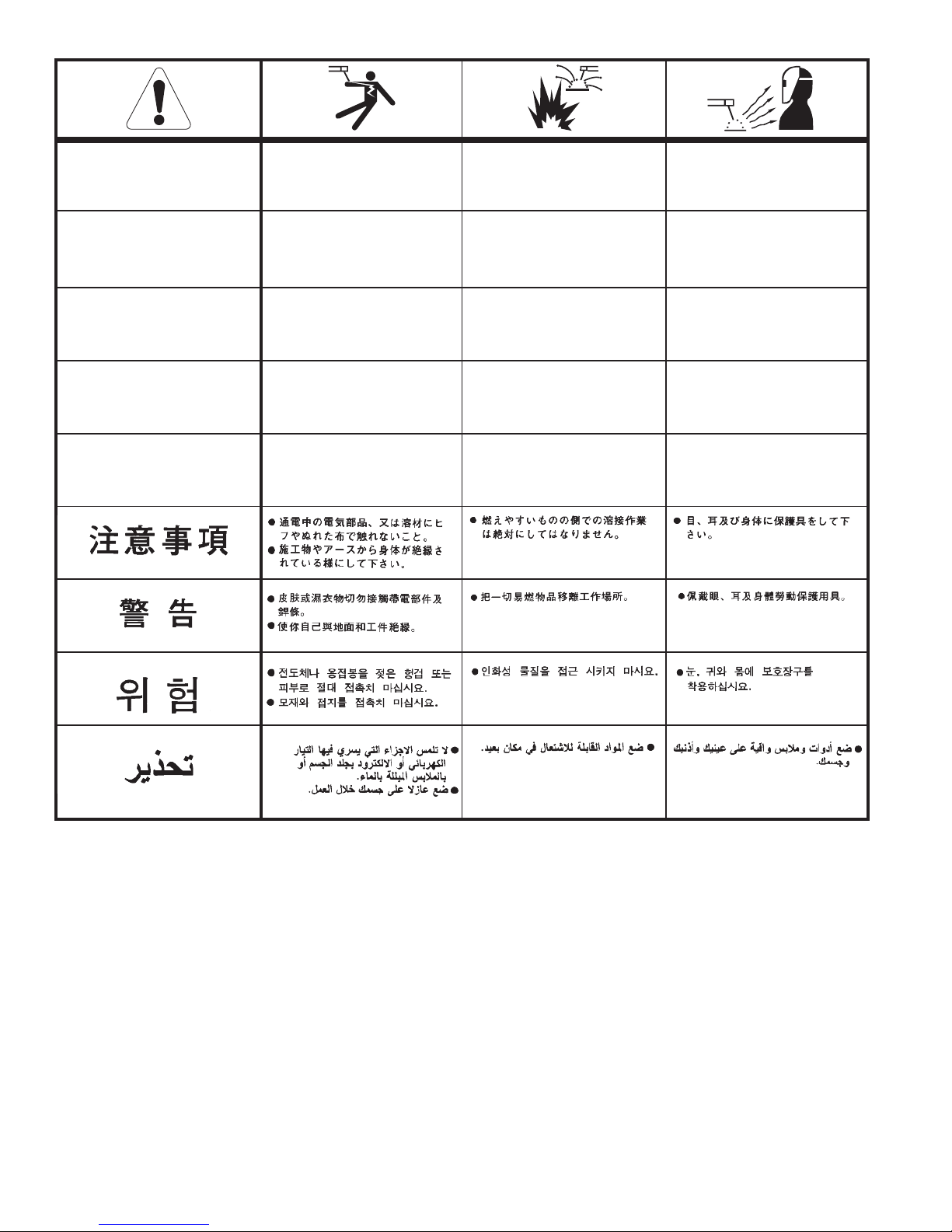
WARNING
AVISO DE
PRECAUCION
ATTENTION
WARNUNG
ATENÇÃO
Spanish
F
rench
G
erman
Portuguese
Japanese
Chinese
Korean
Arabic
READ AND UNDERSTAND THE MANUFACTURER’S INSTRUCTION FOR THIS EQUIPMENT AND THE CONSUMABLES TO BE
USED AND FOLLOW YOUR EMPLOYER’S SAFETY PRACTICES.
SE RECOMIENDA LEER Y ENTENDER LAS INSTRUCCIONES DEL FABRICANTE PARA EL USO DE ESTE EQUIPO Y LOS
CONSUMIBLES QUE VA A UTILIZAR, SIGA LAS MEDIDAS DE SEGURIDAD DE SU SUPERVISOR.
LISEZ ET COMPRENEZ LES INSTRUCTIONS DU FABRICANT EN CE QUI REGARDE CET EQUIPMENT ET LES PRODUITS A
ETRE EMPLOYES ET SUIVEZ LES PROCEDURES DE SECURITE DE VOTRE EMPLOYEUR.
LESEN SIE UND BEFOLGEN SIE DIE BETRIEBSANLEITUNG DER ANLAGE UND DEN ELEKTRODENEINSATZ DES
HERSTELLERS. DIE UNFALLVERHÜTUNGSVORSCHRIFTEN DES ARBEITGEBERS SIND EBENFALLS ZU BEACHTEN.
l Do not touch electrically live parts or
electrode with skin or wet clothing.
l Insulate yourself from work and
ground.
l
No toque las partes o los electrodos
bajo carga con la piel o ropa
mojada.
l
Aislese del trabajo y de la tierra.
l
Ne laissez ni la peau ni des
vêtements mouillés entrer en contact
avec des pièces sous tension.
l Isolez-vous du travail et de la terre.
l
Berühren Sie keine stromführenden
Teile oder Elektroden mit Ihrem
Körper oder feuchter Kleidung!
l Isolieren Sie sich von den
Elektroden und dem Erdboden!
l Não toque partes elétricas e
electrodos com a pele ou roupa
molhada.
l Isole-se da peça e terra.
l Keep flammable materials away.
l
Mantenga el material combustible
fuera del área de trabajo.
l Gardez à l’écart de tout matériel
inflammable.
l Entfernen Sie brennbarres Material!
l Mantenha inflamáveis bem
guardados.
l Wear eye, ear and body protection.
l
Protéjase los ojos, los oídos y el
cuerpo.
l Protégez vos yeux, vos oreilles et
votre corps.
l Tragen Sie Augen-, Ohren- und Kör-
perschutz!
l Use proteção para a vista, ouvido e
corpo.
Page 63

WARNING
AVISO DE
PRECAUCION
ATTENTION
WARNUNG
ATENÇÃO
Spanish
F
rench
G
erman
Portuguese
Japanese
Chinese
Korean
Arabic
LEIA E COMPREENDA AS INSTRUÇÕES DO FABRICANTE PARA ESTE EQUIPAMENTO E AS PARTES DE USO, E SIGA AS
PRÁTICAS DE SEGURANÇA DO EMPREGADOR.
l Keep your head out of fumes.
l Use ventilation or exhaust to
remove fumes from breathing zone.
l Los humos fuera de la zona de
respiración.
l
Mantenga la cabeza fuera de los
humos. Utilice ventilación o
aspiración para gases.
l
Gardez la tête à l’écart des fumées.
l
Utilisez un ventilateur ou un
aspirateur pour ôter les fumées des
zones de travail.
l Vermeiden Sie das Einatmen von
Schweibrauch!
l
Sorgen Sie für gute Be- und
Entlüftung des Arbeitsplatzes!
l
Mantenha seu rosto da fumaça.
l
Use ventilação e exhaustão para
remover fumo da zona respiratória.
l Turn power off before servicing.
l
Desconectar el cable de
alimentación de poder de la
máquina antes de iniciar cualquier
servicio.
l
Débranchez le courant avant
l’entretien.
l
Strom vor Wartungsarbeiten
abschalten! (Netzstrom völlig
öffnen; Maschine anhalten!)
l Não opere com as tampas removidas.
l Desligue a corrente antes de fazer
serviço.
l Do not operate with panel open or
guards off.
l
No operar con panel abierto o
guardas quitadas.
l N’opérez pas avec les panneaux
ouverts ou avec les dispositifs de
protection enlevés.
l Anlage nie ohne Schutzgehäuse
oder Innenschutzverkleidung in
Betrieb setzen!
l Mantenha-se afastado das partes
moventes.
l
Não opere com os paineis abertos
ou guardas removidas.
Page 64

Customer assistanCe PoliCy
The business of The Lincoln Electric Company is manufacturing and
selling high quality welding equipment, consumables, and cutting
equipment. Our challenge is to meet the needs of our customers and
t
o exceed their expectations. On occasion, purchasers may ask
Lincoln Electric for advice or information about their use of our
products. We respond to our customers based on the best information
in our possession at that time. Lincoln Electric is not in a position to
warrant or guarantee such advice, and assumes no liability, with
respect to such information or advice. We expressly disclaim any
warranty of any kind, including any warranty of fitness for any
customer’s particular purpose, with respect to such information or
advice. As a matter of practical consideration, we also cannot assume
any responsibility for updating or correcting any such information or
advice once it has been given, nor does the provision of information
or advice create, expand or alter any warranty with respect to the sale
of our products.
Lincoln Electric is a responsive manufacturer, but the selection and
use of specific products sold by Lincoln Electric is solely within the
control of, and remains the sole responsibility of the customer. Many
variables beyond the control of Lincoln Electric affect the results
obtained in applying these types of fabrication methods and service
requirements.
Subject to Change – This information is accurate to the best of our
knowledge at the time of printing. Please refer to
www.lincolnelectric.com for any updated information.
TABLE OF CONTENTS
INSTALLATION
OPERATION
MAINTENANCE
TROUBLESHOOTING
D
IAGRAMS
 Loading...