

Page 1
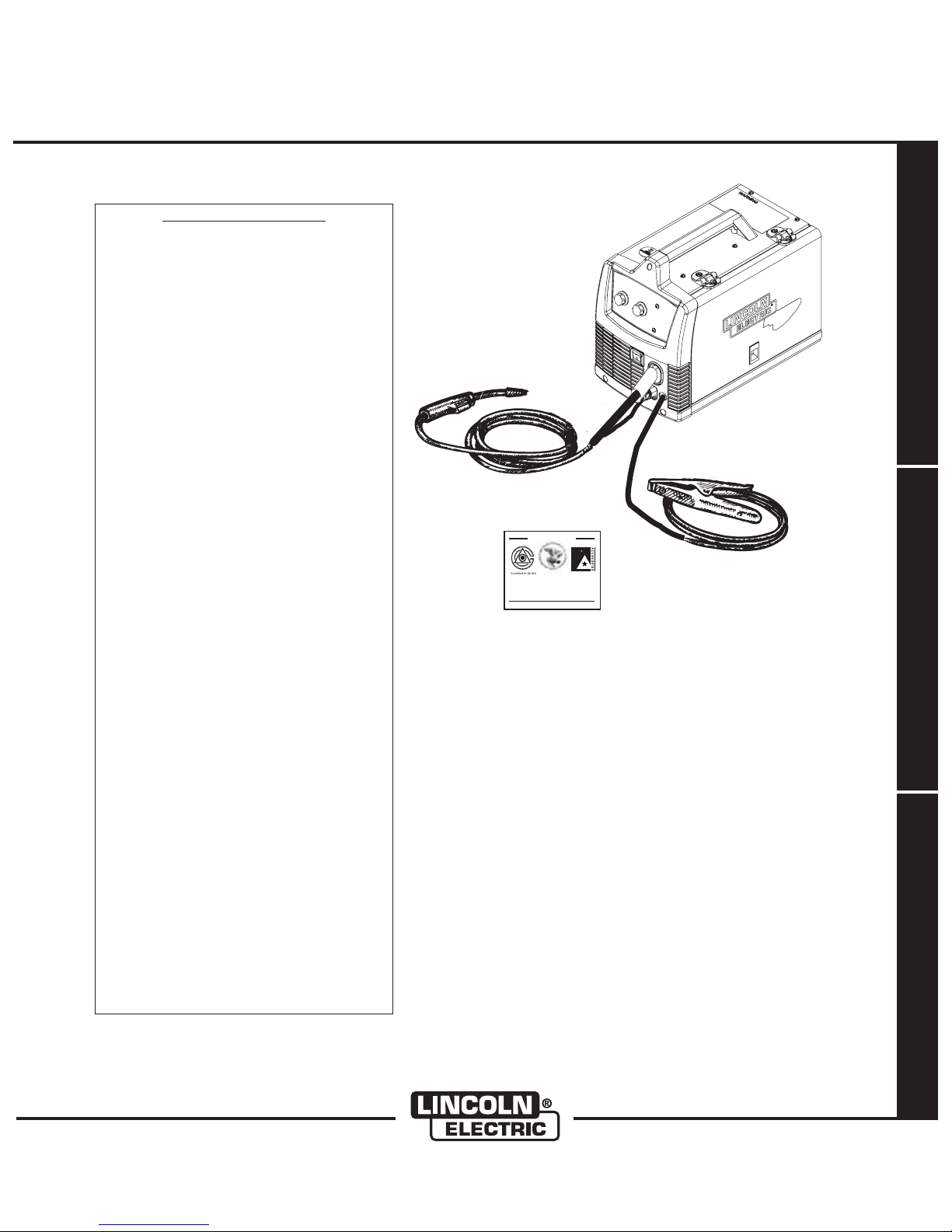
WIRE FEEDER
WELDER (125, 140, 180 MODELS)
IM891-C
January, 2009
For use with machines having Code Numbers:
TABLE OF CONTENTS
Installation ...........................Section A
Technical Specifications ...................A-1,A-2
SafetyPrecautions...........................A-2
Location .................................A-2
Stacking .................................A-2
Tilting ...................................A-2
Identify and Locate Components for 180 Amp
and140AmpUnits .........................A-3
Identify and Locate Components for 125 Amp
FluxCoreUnit.............................A-3
Operation ............................Section B
Safety and Product Description .................B-1
ControlsandSettings.....................B-2,B-3
DriveRollandWireGuidesTable ...............B-4
Setting Up and Making a Flux-Cored Weld .B-4 thru B-6
Setting Up and Making a MIG Weld and
InstallShieldingGas ................B-7thruB-10
Setting Up and Making a Aluminum Weld ........B-11
11173 thru 11506, 11550
ISO 9001
ANSI RAB
QMS
Designed and Manufactured Under aI
Quality Program Certified byI
ABS Quality Evaluations, Inc.I
to ISO 9001 Requirements.
CERTIFICATE NUMBER: 30273
OPERATOR’S MANUAL
Accessories . . . .......................Section C
Optional Accessories .........................C-1
Utility Carts ............................C-2,C-3
Maintenance..........................Section D
SafetyPrecautions ..........................D-1
Wire Feed Compartment, Fan Motor, Wire Reel
Maintenance ..............................D-1
GunAndCableMaintenance ..................D-2
OverloadProtection..........................D-2
Component Replacement Procedures ...........D-2
Troubleshooting ......................Section E
SafetyPrecautions...........................E-1
How to Use Troubleshooting Guide ..............E-1
Troubleshooting Guide .................E-2thruE-3
Wiring Diagram and Dimension Print .....Section F
Safety Depends on You
Lincoln arc welding and cutting
equipment is designed and built
with safety in mind. However, your
overall safety can be increased by
proper installation ... and thoughtful operation on your part. DO
NOT INSTALL, OPERATE OR
REPAIR THIS EQUIPMENT
WITHOUT READING THIS
MANUAL AND THE SAFETY
PRECAUTIONS CONTAINED
THROUGHOUT. And, most
importantly, think before you act
and be careful.
MANUAL DE OPERACIÓN
MANUEL DE L’OPÉRATEUR
• Sales and Service through Subsidiaries and Distributors Worldwide •
Cleveland, Ohio 44117-1199 U.S.A. TEL: 216.481.8100 FAX: 216.486.1751 WEB SITE: www.lincolnelectric.com
Copyright © Lincoln Global Inc.
• World's Leader in Welding and Cutting Products •
Page 2
i
SAFETY
WARNING
CALIFORNIA PROPOSITION 65 WARNINGS
Diesel engine exhaust and some of its constituents
are known to the State of California to cause cancer, birth defects, and other reproductive harm.
The Above For Diesel Engines
ARC WELDING CAN BE HAZARDOUS. PROTECT YOURSELF AND OTHERS FROM POSSIBLE SERIOUS INJURY OR DEATH.
KEEP CHILDREN AWAY. PACEMAKER WEARERS SHOULD CONSULT WITH THEIR DOCTOR BEFORE OPERATING.
Read and understand the following safety highlights. For additional safety information, it is strongly recommended that you
purchase a copy of “Safety in Welding & Cutting - ANSI Standard Z49.1” from the American Welding Society, P.O. Box
351040, Miami, Florida 33135 or CSA Standard W117.2-1974. A Free copy of “Arc Welding Safety” booklet E205 is available
from the Lincoln Electric Company, 22801 St. Clair Avenue, Cleveland, Ohio 44117-1199.
BE SURE THAT ALL INSTALLATION, OPERATION, MAINTENANCE AND REPAIR PROCEDURES ARE
PERFORMED ONLY BY QUALIFIED INDIVIDUALS.
The engine exhaust from this product contains
chemicals known to the State of California to cause
cancer, birth defects, or other reproductive harm.
The Above For Gasoline Engines
i
FOR ENGINE
powered equipment.
1.a. Turn the engine off before troubleshooting and maintenance
work unless the maintenance work requires it to be running.
____________________________________________________
____________________________________________________
____________________________________________________
1.d. Keep
position and in good repair.Keep hands, hair, clothing and
tools away from V-belts, gears, fans and all other moving
parts when starting, operating or repairing equipment.
____________________________________________________
1.e. I n so me cases it may be ne cessary to remove
guards to perform required maintenance. Remove
guards only when necessary and replace them when the
maintenance requiring their removal is complete.
Always use the greatest care when working near moving
parts.
___________________________________________________
1.b. Operate engines in open, well-ventilated
areas or vent the engine exhaust fumes
outdoors.
1.c. Do not add the fuel
welding arc or when the engine is running.
Stop the engine and allow it to cool before
refueling to prevent spilled fuel from vaporizing on contact with hot engine parts and
igniting. Do not spill fuel when filling tank. If
fuel is spilled, wipe it up and do not start
engine until fumes have been eliminated.
all equipment safety guards, covers and devices in
1.f. Do not put your hands near the engine fan.
Do not attempt to override the governor or
idler by pushing on the throttle control rods
while the engine is running.
near an open flame
safety
1.h. To avoid scalding, do not remove the
radiator pressure cap when the engine is
hot.
ELECTRIC AND
MAGNETIC FIELDS
may be dangerous
2.a. Electric current flowing through any conductor causes
localized Electric and Magnetic Fields (EMF). Welding
current creates EMF fields around welding cables and
welding machines
2.b. E MF fields may interfere with some pacemakers, and
welders having a pacemaker should consult their physician
before welding.
2.c. Exposure to EMF fields in welding may have other health
effects which are now not known.
2.d. All welders should use the following procedures in order to
minimize exposure to EMF fields from the welding circuit:
Route the electrode and work cables together - Secure
2.d.1.
them with tape when possible.
2.d.2. Never coil the electrode lead around your body.
2.d.3. Do not place your body between the electrode and
work cables. If the electrode cable is on your right
side, the work cable should also be on your right side.
___________________________________________________
1.g. To prevent accidentally starting gasoline engines while
turning
the engine or welding generator during maintenance
work, disconnect the spark plug wires, distributor cap or
magneto wire as appropriate.
2.d.4. Connect the work cable to the workpiece as close as
possible to the area being welded.
2.d.5. Do not work next to welding power source.
Mar ‘95
Page 3
ii
SAFETY
ii
ELECTRIC SHOCK can
kill.
3.a. The electrode and work (or ground) circuits
are electrically “hot” when the welder is on.
Do not touch these “hot” parts with your bare
skin or wet clothing. Wear dry, hole-free
gloves to insulate hands.
3.b. Insulate yourself from work and ground using dry insulation.
Make certain the insulation is large enough to cover your full
area of physical contact with work and ground.
In addition to the normal safety precautions, if welding
must be performed under electrically hazardous
conditions (in damp locations or while wearing wet
clothing; on metal structures such as floors, gratings or
scaffolds; when in cramped positions such as sitting,
kneeling or lying, if there is a high risk of unavoidable or
accidental contact with the workpiece or ground) use
the following equipment:
• Semiautomatic DC Constant Voltage (Wire) Welder.
• DC Manual (Stick) Welder.
• AC Welder with Reduced Voltage Control.
3.c. In semiautomatic or automatic wire welding, the electrode,
electrode reel, welding head, nozzle or semiautomatic
welding gun are also electrically “hot”.
3.d. Always be sure the work cable makes a good electrical
connection with the metal being welded. The connection
should be as close as possible to the area being welded.
3.e. Ground the work or metal to be welded to a good electrical
(earth) ground.
ARC RAYS can burn.
4.a. Use a shield with the proper filter and cover
plates to protect your eyes from sparks and
the rays of the arc when welding or observing
open arc welding. Headshield and filter lens
should conform to ANSI Z87. I standards.
4.b. Use suitable clothing made from durable flame-resistant
material to protect your skin and that of your helpers from
the arc rays.
4.c. Protect other nearby personnel with suitable, non-flammable
screening and/or warn them not to watch the arc nor expose
themselves to the arc rays or to hot spatter or metal.
FUMES AND GASES
can be dangerous.
5.a. Welding may produce fumes and gases
hazardous to health. Avoid breathing these
fumes and gases.When welding, keep
your head out of the fume. Use enough
ventilation and/or exhaust at the arc to keep
fumes and gases away from the breathing zone. When
welding with electrodes which require special
ventilation such as stainless or hard facing (see
instructions on container or MSDS) or on lead or
cadmium plated steel and other metals or coatings
which produce highly toxic fumes, keep exposure as
low as possible and below Threshold Limit Values (TLV)
using local exhaust or mechanical ventilation. In
confined spaces or in some circumstances, outdoors, a
respirator may be required. Additional precautions are
also required when welding on galvanized steel.
OPERATOR’S MANUAL
3.f.
Maintain the electrode holder, work clamp, welding cable and
welding machine in good, safe operating condition. Replace
damaged insulation.
3.g. Never dip the electrode in water for cooling.
3.h. Never simultaneously touch electrically “hot” parts of
electrode holders connected to two welders because voltage
between the two can be the total of the open circuit voltage
of both welders.
3.i. When working above floor level, use a safety belt to protect
yourself from a fall should you get a shock.
3.j. Also see Items 6.c. and 8.
5. b. The operation of welding fume control equipment is affected
by various factors including proper use and positioning of
the equipment, maintenance of the equipment and the specific welding procedure and application involved. Worker
exposure level should be checked upon installation and
periodically thereafter to be certain it is within applicable
OSHA PEL and ACGIH TLV limits.
Do not weld in locations near chlorinated hydrocarbon
5.c.
coming from degreasing, cleaning or spraying operations.
The heat and rays of the arc can react with solvent vapors
form phosgene, a highly toxic gas, and other irritating products.
5.d. Shielding gases used for arc welding can displace air and
cause injury or death. Always use enough ventilation,
especially in confined areas, to insure breathing air is safe.
5.e. Read and understand the manufacturer’s instructions for this
equipment and the consumables to be used, including the
material safety data sheet (MSDS) and follow your
employer’s safety practices. MSDS forms are available from
your welding distributor or from the manufacturer.
5.f. Also see item 1.b.
vapors
AUG 06
to
Page 4
iii
SAFETY
iii
WELDING and CUTTING
SPARKS can
cause fire or explosion.
6.a.
Remove fire hazards from the welding area.
If this is not possible, cover them to prevent
Remember that welding sparks and hot
materials from welding can easily go through small cracks
and openings to adjacent areas. Avoid welding near
hydraulic lines. Have a fire extinguisher readily available.
6.b. Where compressed gases are to be used at the job site,
special precautions should be used to prevent hazardous
situations. Refer to “Safety in Welding and Cutting” (ANSI
Standard Z49.1) and the operating information for the
equipment being used.
6.c. When not welding, make certain no part of the electrode
circuit is touching the work or ground. Accidental contact
can cause overheating and create a fire hazard.
6.d. Do not heat, cut or weld tanks, drums or containers until the
proper steps have been taken to insure that such procedures
will not cause flammable or toxic vapors from substances
inside. They can cause an explosion even
been “cleaned”. For information, purchase “Recommended
Safe Practices for the
Containers and Piping That Have Held Hazardous
Substances”, AWS F4.1 from the American Welding Society
(see address above).
6.e. Vent hollow castings or containers before heating, cutting or
welding. They may explode.
Sparks and spatter are thrown from the welding arc. Wear oil
6.f.
free protective garments such as leather gloves, heavy shirt,
cuffless trousers, high shoes and a cap over your hair. Wear
ear plugs when welding out of position or in confined places.
Always wear safety glasses with side shields when in a
welding area.
6.g. Connect the work cable to the work as close to the welding
area as practical. Work cables connected to the building
framework or other locations away from the welding area
increase the possibility of the welding current passing
through lifting chains, crane cables or other alternate circuits. This can create fire hazards or overheat lifting chains
or cables until they fail.
6.h. Also see item 1.c.
the welding sparks from starting a fire.
though
they have
Preparation
for Welding and Cutting of
CYLINDER may explode
if damaged.
7.a. Us e only compressed gas cylinders
containing the correct shielding gas for the
process used and properly operating
regulators designed for the gas and
pressure used. All hoses, fittings, etc. should be suitable for
the application and maintained in good condition.
7.b. Always keep cylinders in an upright position securely
chained to an undercarriage or fixed support.
7.c. Cylinders should be located:
• Away from areas where they may be struck or subjected to
physical damage.
• A safe distance from arc welding or cutting operations and
any other source of heat, sparks, or flame.
7.d. Never allow the electrode, electrode holder or any other
electrically “hot” parts to touch a cylinder.
7.e. Keep your head and face away from the cylinder valve outlet
when opening the cylinder valve.
7.f. Valve protection caps should always be in place and hand
tight except when the cylinder is in use or connected for
use.
7.g. Read and follow the instructions on compressed gas
cylinders, associated equipment, and CGA publication P-l,
“Precautions for Safe Handling of Compressed Gases in
Cylinders,” available from the Compressed Gas Association
1235 Jefferson Davis Highway, Arlington, VA 22202.
FOR ELECTRICALLY
powered equipment.
8.a. Turn off input power using the disconnect
switch at the fuse box before working on
the equipment.
8.b. Install equipment in accordance with the U.S. National
Electrical Code, all local codes and the manufacturer’s
recommendations.
8.c. Ground the equipment in accordance with the U.S. National
Electrical Code and the manufacturer’s recommendations.
6.I. Read and follow NFPA 51B “ Standard for Fire Prevention
During Welding, Cutting and Other Hot Work”, available
from NFPA, 1 Batterymarch Park,PO box 9101, Quincy, Ma
022690-9101.
6.j. Do not use a welding power source for pipe thawing.
Jan, 07
Page 5

iv
SAFETY
iv
PRÉCAUTIONS DE SÛRETÉ
Pour votre propre protection lire et observer toutes les instructions et les précautions de sûreté specifiques qui parraissent
dans ce manuel aussi bien que les précautions de sûreté
générales suivantes:
Sûreté Pour Soudage A L’Arc
1. Protegez-vous contre la secousse électrique:
a. Les circuits à l’électrode et à la piéce sont sous tension
quand la machine à souder est en marche. Eviter toujours
tout contact entre les parties sous tension et la peau nue
ou les vétements mouillés. Porter des gants secs et sans
trous pour isoler les mains.
b. Faire trés attention de bien s’isoler de la masse quand on
soude dans des endroits humides, ou sur un plancher
metallique ou des grilles metalliques, principalement dans
les positions assis ou couché pour lesquelles une
grande partie du corps peut être en contact avec la
masse.
c. Maintenir le porte-électrode, la pince de masse, le câble
de soudage et la machine à souder en bon et sûr état
defonctionnement.
d.Ne jamais plonger le porte-électrode dans l’eau pour le
refroidir.
e. Ne jamais toucher simultanément les parties sous tension
des porte-électrodes connectés à deux machines à souder parce que la tension entre les deux pinces peut être le
total de la tension à vide des deux machines.
f. Si on utilise la machine à souder comme une source de
courant pour soudage semi-automatique, ces precautions
pour le porte-électrode s’applicuent aussi au pistolet de
soudage.
5. Toujours porter des lunettes de sécurité dans la zone de
soudage. Utiliser des lunettes avec écrans lateraux dans les
zones où l’on pique le laitier.
6. Eloigner les matériaux inflammables ou les recouvrir afin de
prévenir tout risque d’incendie dû aux étincelles.
7. Quand on ne soude pas, poser la pince à une endroit isolé de
la masse. Un court-circuit accidental peut provoquer un
échauffement et un risque d’incendie.
8. S’assurer que la masse est connectée le plus prés possible
de la zone de travail qu’il est pratique de le faire. Si on place
la masse sur la charpente de la construction ou d’autres
endroits éloignés de la zone de travail, on augmente le risque
de voir passer le courant de soudage par les chaines de levage, câbles de grue, ou autres circuits. Cela peut provoquer
des risques d’incendie ou d’echauffement des chaines et des
câbles jusqu’à ce qu’ils se rompent.
9. Assurer une ventilation suffisante dans la zone de soudage.
Ceci est particuliérement important pour le soudage de tôles
galvanisées plombées, ou cadmiées ou tout autre métal qui
produit des fumeés toxiques.
10. Ne pas souder en présence de vapeurs de chlore provenant
d’opérations de dégraissage, nettoyage ou pistolage. La
chaleur ou les rayons de l’arc peuvent réagir avec les
vapeurs du solvant pour produire du phosgéne (gas fortement toxique) ou autres produits irritants.
11. Pour obtenir de plus amples renseignements sur la sûreté,
voir le code “Code for safety in welding and cutting” CSA
Standard W 117.2-1974.
OPERATOR’S MANUAL
2. Dans le cas de travail au dessus du niveau du sol, se protéger contre les chutes dans le cas ou on recoit un choc. Ne
jamais enrouler le câble-électrode autour de n’importe quelle
partie du corps.
3. Un coup d’arc peut être plus sévère qu’un coup de soliel,
donc:
a. Utiliser un bon masque avec un verre filtrant approprié
ainsi qu’un verre blanc afin de se protéger les yeux du
rayonnement de l’arc et des projections quand on soude
ou quand on regarde l’arc.
b. Porter des vêtements convenables afin de protéger la
peau de soudeur et des aides contre le rayonnement de
l‘arc.
c. Protéger l’autre personnel travaillant à proximité au
soudage à l’aide d’écrans appropriés et non-inflammables.
4. Des gouttes de laitier en fusion sont émises de l’arc de
soudage. Se protéger avec des vêtements de protection
libres de l’huile, tels que les gants en cuir, chemise épaisse,
pantalons sans revers, et chaussures montantes.
WIRE FEEDER WELDERS (125, 140, 180 MODELS)
PRÉCAUTIONS DE SÛRETÉ POUR
LES MACHINES À SOUDER À
TRANSFORMATEUR ET À
REDRESSEUR
1. Relier à la terre le chassis du poste conformement au code
de l’électricité et aux recommendations du fabricant. Le dispositif de montage ou la piece à souder doit être branché à
une bonne mise à la terre.
2. Autant que possible, I’installation et l’entretien du poste
seront effectués par un électricien qualifié.
3. Avant de faires des travaux à l’interieur de poste, la
debrancher à l’interrupteur à la boite de fusibles.
4. Garder tous les couvercles et dispositifs de sûreté à leur
place.
Mar. ‘93
Page 6
Thank You
iviv
for selecting a QUALITY product by Lincoln Electric. We want you
to take pride in operating this Lincoln Electric Company product
••• as much pride as we have in bringing this product to you!
The business of The Lincoln Electric Company is manufacturing and selling high quality welding equipment, consumables, and cutting equipment. Our challenge is to meet the needs of our customers and to exceed their expectations. On occasion, purchasers may ask Lincoln
Electric for advice or information about their use of our products. We respond to our customers based on the best information in our possession at that time. Lincoln Electric is not in a position to warrant or guarantee such advice, and assumes no liability, with respect to such information or advice. We expressly disclaim any warranty of any kind, including any warranty of fitness for any customer’s particular purpose,
with respect to such information or advice. As a matter of practical consideration, we also cannot assume any responsibility for updating or
correcting any such information or advice once it has been given, nor does the provision of information or advice create, expand or alter any
warranty with respect to the sale of our products.
Lincoln Electric is a responsive manufacturer, but the selection and use of specific products sold by Lincoln Electric is solely within the control
of, and remains the sole responsibility of the customer. Many variables beyond the control of Lincoln Electric affect the results obtained in
applying these types of fabrication methods and service requirements.
Subject to Change – This information is accurate to the best of our knowledge at the time of printing. Please refer to www.lincolnelectric.com
for any updated information.
CUSTOMER ASSISTANCE POLICY
Please Examine Carton and Equipment For Damage Immediately
When this equipment is shipped, title passes to the purchaser upon receipt by the carrier. Consequently, Claims
for material damaged in shipment must be made by the purchaser against the transportation company at the
time the shipment is received.
Please record your equipment identification information below for future reference. This information can be
found on your machine nameplate.
Product _________________________________________________________________________________
Model Number ___________________________________________________________________________
Code Number or Date Code_________________________________________________________________
Serial Number____________________________________________________________________________
Date Purchased___________________________________________________________________________
Where Purchased_________________________________________________________________________
Whenever you request replacement parts or information on this equipment, always supply the information you
have recorded above. The code number is especially important when identifying the correct replacement parts.
On-Line Product Registration
- Register your machine with Lincoln Electric either via fax or over the Internet.
• For faxing: Complete the form on the back of the warranty statement included in the literature packet
accompanying this machine and fax the form per the instructions printed on it.
• For On-Line Registration: Go to our
“Product Registration”. Please complete the form and submit your registration.
Read this Operators Manual completely before attempting to use this equipment. Save this manual and keep it
handy for quick reference. Pay particular attention to the safety instructions we have provided for your protection.
The level of seriousness to be applied to each is explained below:
WEB SITE at www.lincolnelectric.com. Choose “Quick Links” and then
WARNING
This statement appears where the information must be followed exactly to avoid serious personal injury or loss of life.
CAUTION
This statement appears where the information must be followed to avoid minor personal injury or damage to this equipment.
Page 7

INSTALLATION
A-1A-1
TECHNICAL SPECIFICATIONS
180 Amp units (K2481-1, K2515-1, K2659-1, K2689-1, K2698-1)
INPUT – SINGLE PHASE ONLY
Standard Voltage/Frequency Input Current
230 V 60 Hz 20 Amps @ rated output
208 V 60 Hz 20 Amps @ rated output
RATED OUTPUT
Voltage/Duty
230 V 30% 130 Amps 20
208 V 30% 130 Amps 17
Cycle Current Voltage at Rated Amperes
OUTPUT
Welding Current Range
30-180 Amps 34 V 50 - 500 in/min.
Open Circuit Voltage Wire Speed Range
RECOMMENDED INPUT CABLE AND FUSE SIZES
Input Voltage/Frequency Fuse or Breaker Size
230 V 60 Hz 40 Amp Super Lag 20 50 Amp, 250 V,
1
Input Amps Power Cord
PHYSICAL DIMENSIONS
Height Width Depth Weight
13.7 in 10.15 in 17.9 in 64 Ibs
347 mm 258 mm 454 mm 29 kg
1
If connected to a circuit protected by fuses use Time Delay Fuse marked “D”.
(1.3 - 12.7 m/min.)
OPERATOR’S MANUAL
Three Prong Plug
(NEMA Type 6-50P)
140 Amp units (K2480-1, K2514-1, K2658-1, K2688-1, K2697-1)
INPUT – SINGLE PHASE ONLY
Standard Voltage/Frequency Input Current
Input Voltage/Frequency Fuse or Breaker Size
120 V 60 Hz 20 Amp 20 15 Amp, 125 V,
1
If connected to a circuit protected by fuses use Time Delay Fuse marked “D”.
120 V / 60 Hz 20 Amps @ rated output
RATED OUTPUT
Cycle Current Voltage at Rated Amperes
Duty
20% Duty Cycle 90 Amps 19.5
OUTPUT
Welding Current Range Open Circuit Voltage Wire Speed Range
30-140 Amps 33 V 50 - 500 in/min.
RECOMMENDED INPUT CABLE AND FUSE SIZES
1,2
Input Amps Power Cord Extension Cord
Three Prong Plug (4mm2) or Larger
(NEMA Type 5-15P) up to 50 ft.(15.2m)
PHYSICAL DIMENSIONS
Height Width Depth Weight
13.7 in 10.15 in 17.9 in 54 Ibs
347 mm 258 mm 454 mm 24.5 kg
(1.3 - 12.7 m/min.)
3 Conductor # 12 AWG
WIRE FEEDER WELDERS (125, 140, 180 MODELS)
Page 8
A-2
INSTALLATION
A-2
TECHNICAL SPECIFICATIONS
125 Amp units (K2479-1, K2513-1, K2696-1, K2699-1, K2785-1)
INPUT – SINGLE PHASE ONLY
Standard Voltage/Frequency Input Current
120 V / 60 Hz 20 Amps @ rated output
RATED OUTPUT
Cycle Current Voltage at Rated Amperes
Duty
20% Duty Cycle 90 Amps 19
OUTPUT
Welding Current Range Maximum-Open Circuit Voltage Wire Speed Range
30-125 Amps 33 V 50 - 500 in/min.
RECOMMENDED INPUT CABLE AND FUSE SIZES
Input Voltage / Frequency Fuse or Breaker Size
120 V 60 Hz 20 Amp 20 15 Amp, 125 V,
1,2
Input Amps Power Cord Extension Cord
Three Prong Plug (4mm2) or Larger
(NEMA Type 5-15P) up to 50 ft.(15.2m)
PHYSICAL DIMENSIONS
Height Width Depth Weight
13.7 in 10.15 in 17.9 in 48 Ibs
347 mm 258 mm 454 mm 21.7 kg
1
If connected to a circuit protected by fuses use Time Delay Fuse marked “D”.
2
Requirements For Maximum Output
In order to utilize the maximum output capability of
the machine, a branch circuit capable of 25 amps at
120 volts, 60 Hertz is required.
(1.3 - 12.7 m/min.)
3 Conductor # 12 AWG
Read entire installation section before starting
installation.
SAFETY PRECAUTIONS
WARNING
ELECTRIC SHOCK can kill.
• Only qualified personnel should perform
this installation.
• Only personnel that have read and understood the POWER MIG Operating Manual
should install and operate this equipment.
• Machine must be plugged into a receptacle
which is grounded per any national, local
or other applicable electrical codes.
• The POWER MIG power switch is to be in
the OFF (“O”) position when installing
work cable and gun and when connecting
power cord to input power.
WIRE FEEDER WELDERS (125, 140, 180 MODELS)
SELECT SUITABLE LOCATION
Locate the welder in a dry location where there is free
circulation of clean air into the louvers in the back and
out the front of the unit. A location that minimizes the
amount of smoke and dirt drawn into the rear louvers
reduces the chance of dirt accumulation that can
block air passages and cause overheating.
STACKING
WIRE FEEDER WELDER(125, 140, 180 MODELS)
cannot be stacked.
TILTING
Each machine must be placed on a secure, level surface, directly or on recommended cart. The machine
may topple over if this procedure is not followed.
Page 9

A-3
INSTALLATION
A-3
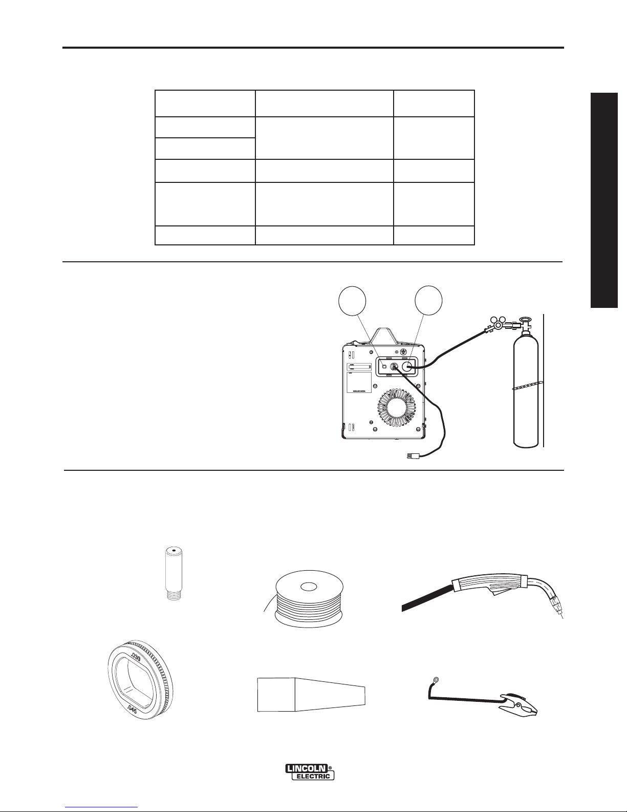
IDENTIFY AND LOCATE
COMPONENTS
for 140 AMP and 180 AMP UNITS
INCLUDED COMPONENTS
• Wire Feeder
Welder.
• Work Cable & Clamp.
• Magnum 100L Welding Gun.
• 3 .035 Contact Tips (1 installed
on the welding gun).
• 3 .025 Contact Tips.
• Handshield
LINCOLN
ELECTRIC
®
• Black Flux-cored Gasless Gun
Nozzle (Installed on Welding
Gun)
• Brass MIG Gas Gun Nozzle
• 2” Spindle Adapter (For 8” Reel of
wire)
• Regulator
• Gas Hose
• Learn to Weld (LTW1 Manual)
• DVD
REGULATOR
2" SPINDLE ADAPTER (FOR 8" REEL OF WIRE)
• Magnum 100L Welding Gun.
• 3 .035 Contact Tips (1 installed on
the welding gun).
.035
.035
• Spool of .035 diameter NR211MP Innershield Flux-cored
Wire.
.035 NR-211 MP
F
L
W
U
D
X
E
-
C
R
O
E
R
I
• .030 -.045 Knurled Drive Roll
(Installed on
Machine)
• Handshield
LINCOLN
ELECTRIC
®
OPERATOR’S MANUAL
.035
.035
.025
.025
• Spool of .035 diameter NR211MP Innershield Flux-cored
Wire.
• Spool of .025 diameter L-56 MIG
Wire.
NR-211 MP
.025-.030 Smooth Drive Roll
•
L-56 MIG
WIRE
• .035 Smooth Drive Roll
• .030 -.045 Knurled
Drive Roll
(Installed on
Machine)
.025
GAS HOSE
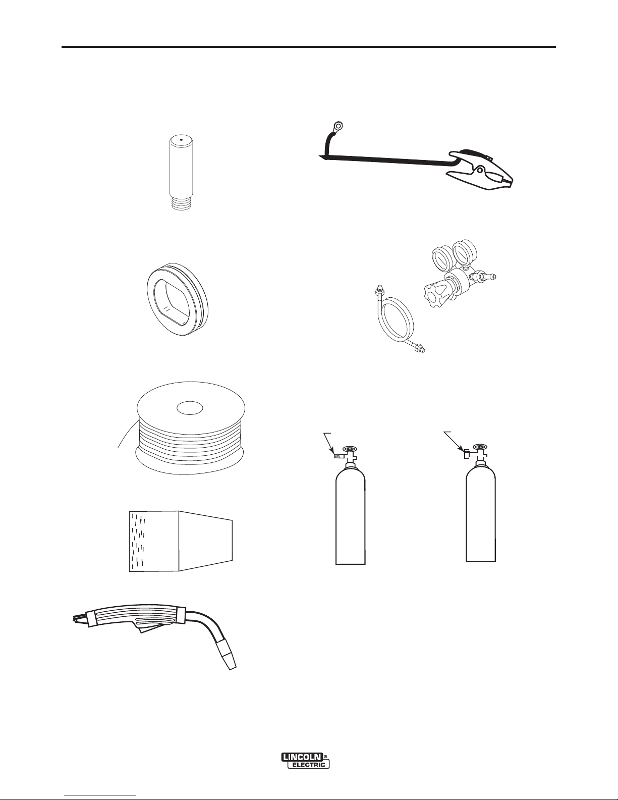
IDENTIFY AND LOCATE
COMPONENTS
for 125 AMP FLUX CORE UNIT
INCLUDED COMPONENTS
•
• Wire Feeder
Welder.
• Work Cable & Clamp.
"LEARN TO WELD"
LTW1
DVD
• Black Flux-cored Gasless Gun
Nozzle (Installed on Welding Gun)
• 2” Spindle Adapter (For 8” Reel of
wire)
• Learn to Weld (LTW1 Manual)
• DVD
2" SPINDLE ADAPTER (FOR 8" REEL OF WIRE)
"LEARN TO WELD"
LTW1
DVD
WIRE FEEDER WELDERS (125, 140, 180 MODELS)
Page 10

B-1
OPERATION
B-1
Read entire operation section before
operating the
WIRE FEEDER WELDERS.
WARNING
ELECTRIC SHOCK can kill.
• Do not touch electrically live
parts or electrode with skin or
wet clothing. Insulate yourself
from work and ground.
• Always wear dry insulating
gloves.
FUMES AND GASES can be
dangerous.
• Keep your head out of fumes.
• Use ventilation or exhaust to
remove fumes from breathing
zone.
WELDING SPARKS can
cause fire or explosion.
• Keep flammable material away.
• Do not weld on closed containers.
ARC RAYS can burn eyes
and skin.
• Wear eye, ear and body protection.
PRODUCT DESCRIPTION (PRODUCT
CAPABILITIES)
These small portable wire feed welders are capable of
MIG welding on steel, stainless steel, and aluminum.
They are also capable of flux-cored welding on mild
steel.
MIG welding stands for Metal Inert Gas welding and
requires a separate bottle of shielding gas to protect
the weld until it cools. Appropriate shielding gas
based on the type of material you are welding can be
purchased separately from your local welding gas distributor. MIG welding is ideal for welding on thinner
and clean materials when a very clean excellent cosmetic looking weld is required. An example would be
automotive body panels.
Self Sheilding Flux-cored Welding does not require
separate shielding gas to protect the weld since the
welding wire has special additives known as flux to
protect the weld until it cools. Flux-cored welding is
ideal for medium to thicker material and if welding on
painted or rusty steel. Flux-cored welding is also ideal
in outdoor applications where windy conditions might
blow the MIG shielding gas away from the weld. Fluxcored welding produces a good looking weld but does
not produce an excellent weld appearance as MIG
welding does.
Your machine includes the necessary items to weld
with either the MIG or the flux-cored welding process
on steel. To weld on stainless steel optional stainless
steel welding wire can be purchased separately. This
machine can weld aluminum using .035 diameter
4043 aluminum welding wire. Since aluminum welding wire is soft an optional aluminum spool gun is recommended for best results. A welding Procedure
Decal is located inside machine door to help provide
suggested settings for welding.
Observe all safety information throughout
this manual.
------------------------------------------------------------
WIRE FEEDER WELDERS (125, 140, 180 MODELS)
COMMON WELDING ABBREVIATIONS
GMAW (MIG)
• Gas Metal Arc Welding
FCAW (Innershield or Outershield)
• Flux Core Arc Welding
Page 11
B-2
1
3
2
CONTROLS AND SETTINGS
This machine has the following controls:
OPERATION
B-2
See Figure B.1
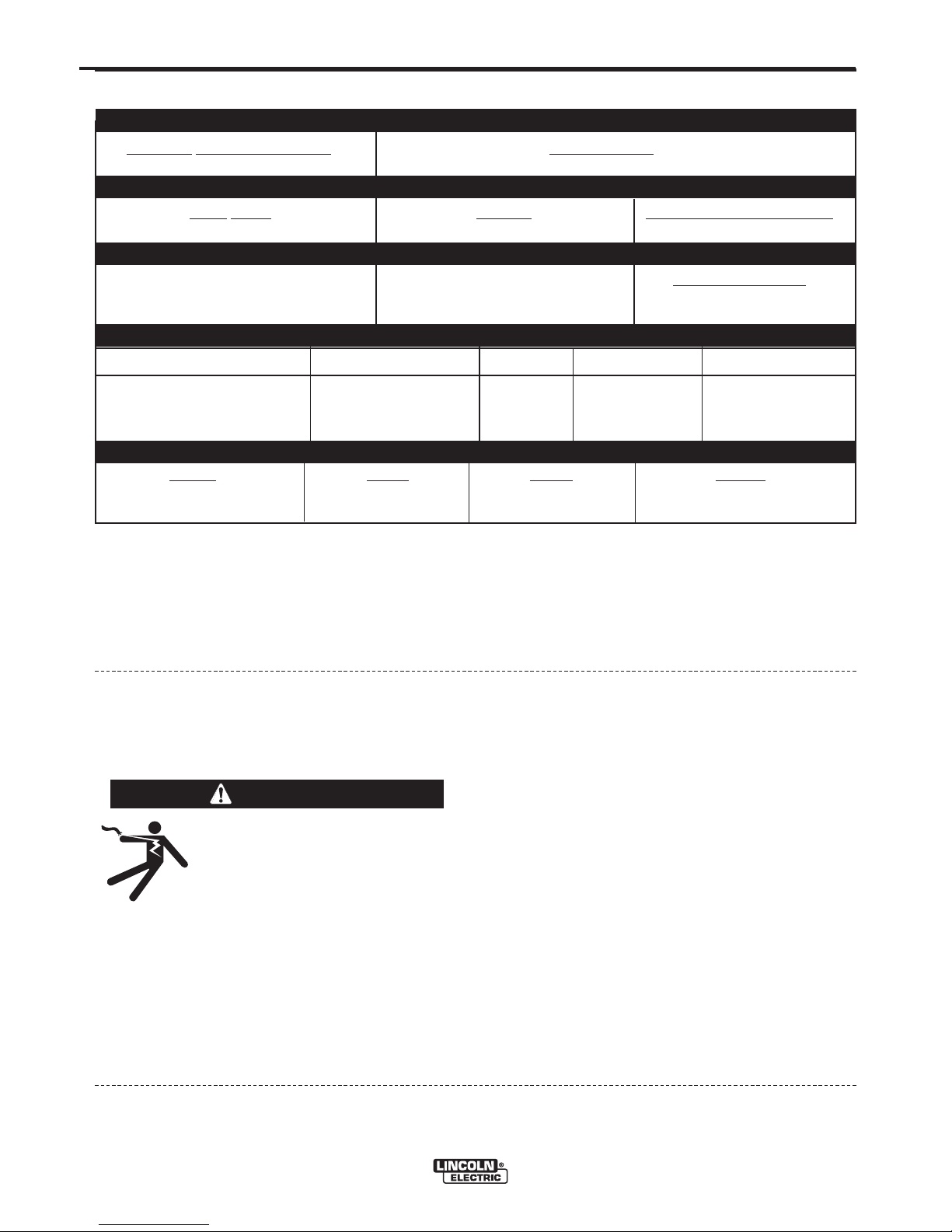
1. POWER SWITCH – Turns power on and off to the
machine.
2. ARC VOLTAGE CONTROL – This knob sets the
output voltage of the machine. Along with wire feed
speed (WFS) this control sets a weld procedure.
Refer to the procedure decal on the inside wire
drive compartment door to set a correct welding
procedure based on type of material and thickness
being welded.
3. WIRE FEED SPEED CONTROL (WFS) – The knob
sets the speed that the machine feeds wire. Along
with arc voltage this control sets a weld procedure.
Refer to the procedure decal on the inside wire
drive compartment door to set a correct welding
procedure based on type of material and thickness
being welded.
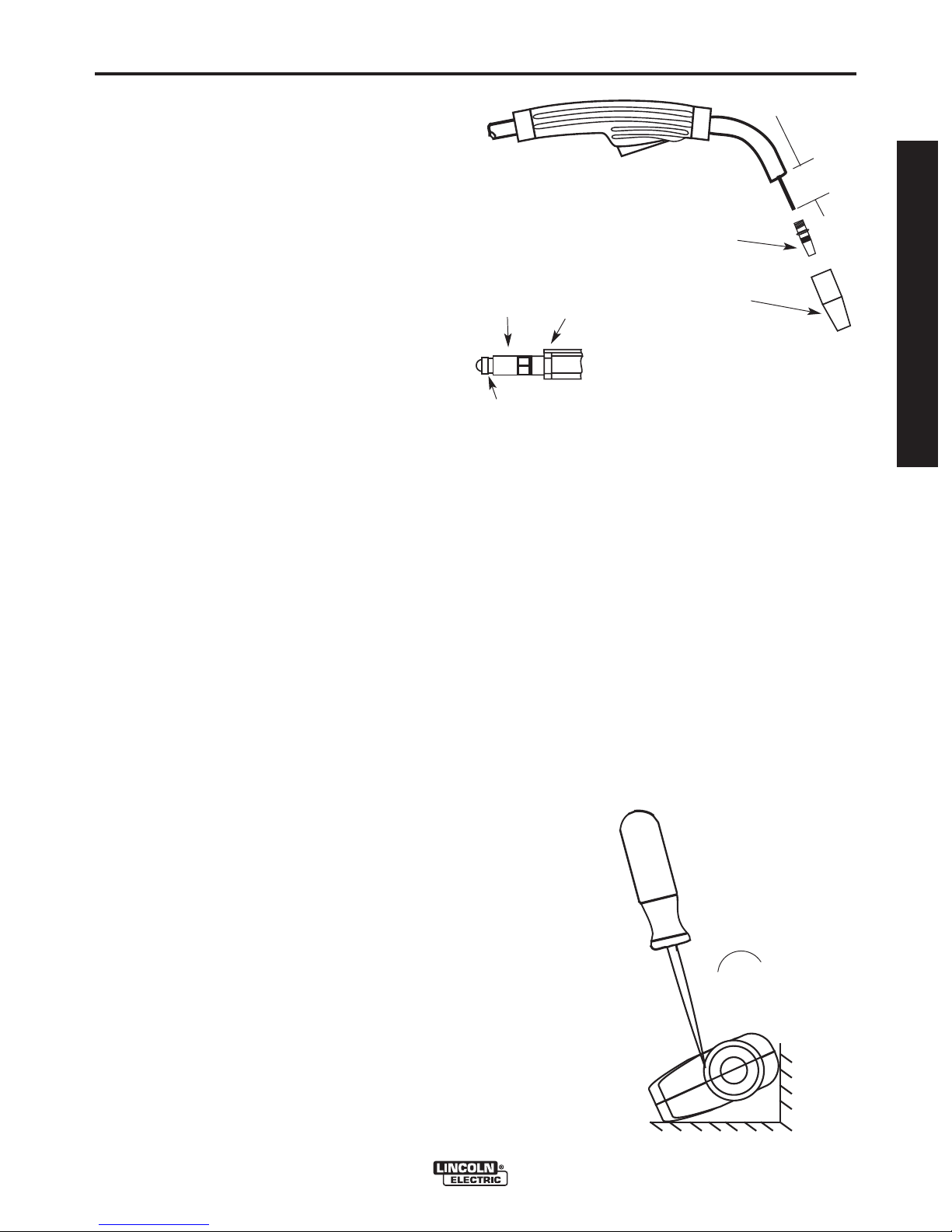
See Figure B.2
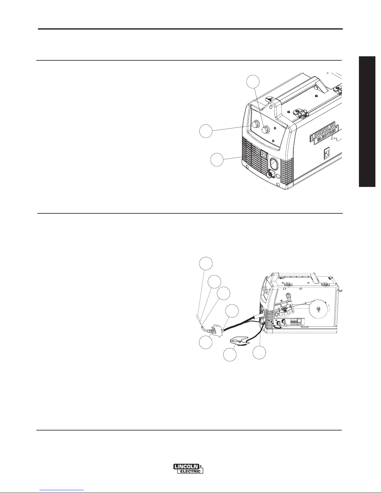
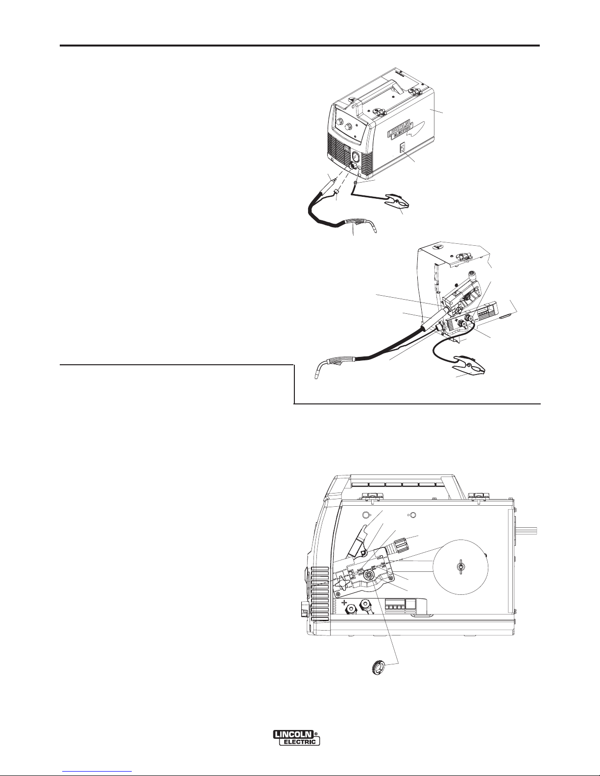
4. GUN TRIGGER – Depress the trigger to activates
the wire drive to feed wire and energizes the output
of the machine. Depress the trigger to weld and
release the trigger to stop welding.
5. WELDING GUN – Delivers wire and welding cur-
rent to the weld.
a. Gun Liner – wire travels through the liner from
the wire drive. The gun liner will feed .025 to .035
wire. The 180A machine can weld with .045 wire
if an optional .045 liner is installed in the gun.
b. Contact Tip – provides electrical contact to the
wire.
5c
5b
5a
FIGURE B.1
OPERATOR’S MANUAL
FIGURE B.2
.035"(0.9mm)
NR-211-MP
5
WIRE SPOOL
c. Nozzle – When flux-cored welding the black noz-
zle protects the mounting threads on the gun.
When MIG welding the brass nozzle funnels the
shielding gas to the weld.
6. WORK CLAMP & CABLE – Clamps to the work
piece being welded and completes the electrical
welding circuit.
7. GUN TRIGGER CONNECTOR RECEPTACLE –
Plug the 4 pin gun trigger connector into this receptacle.
WIRE FEEDER WELDERS (125, 140, 180 MODELS)
4
6
7
Page 12
B-3
OPERATION
B-3
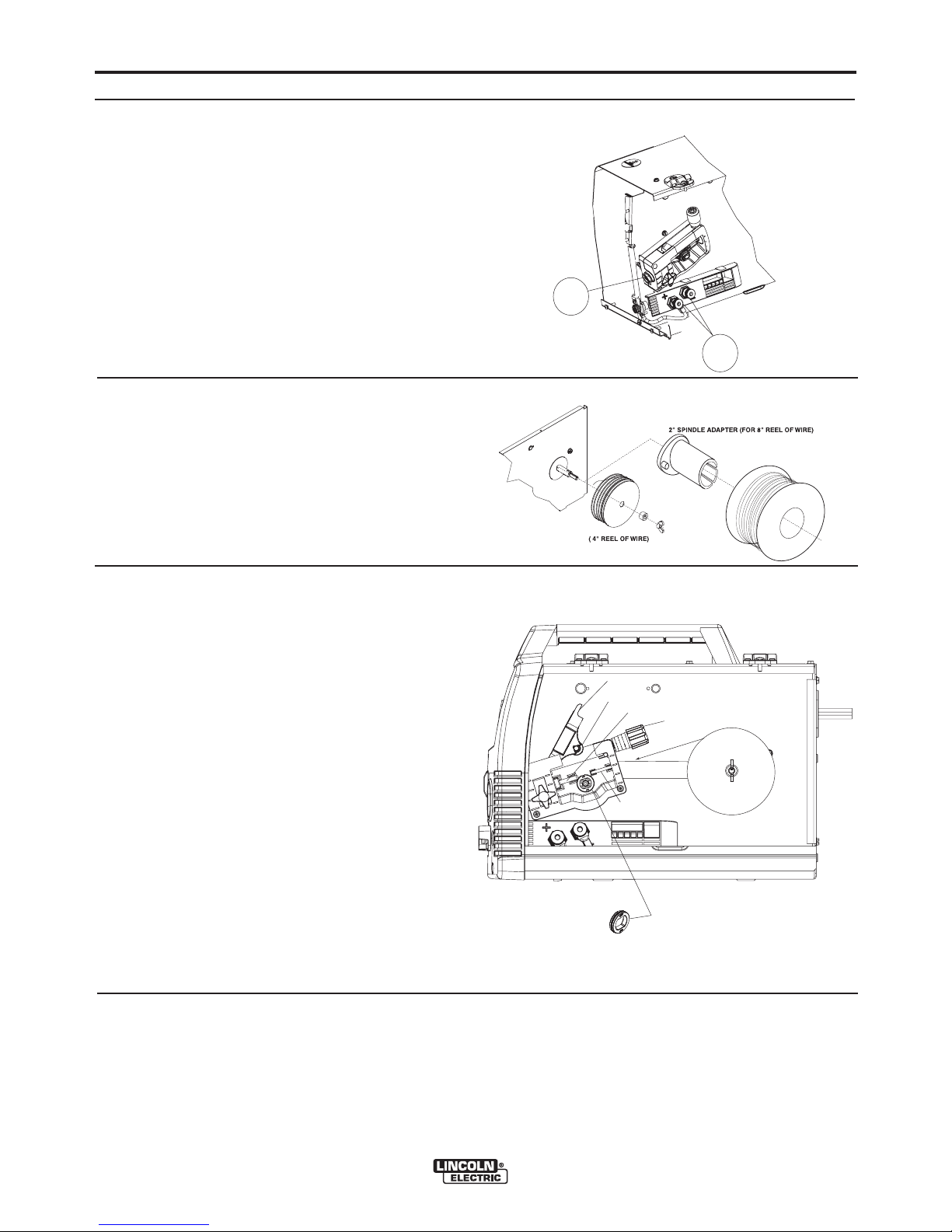
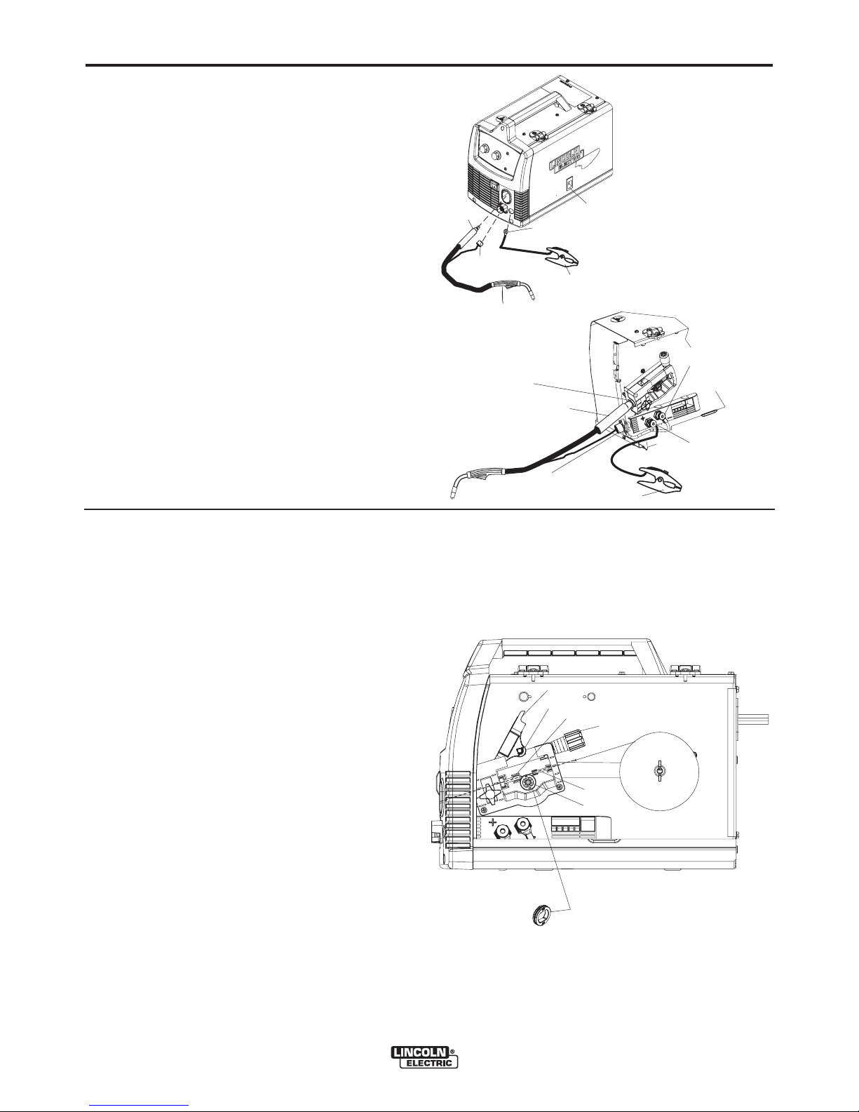
See Figure B.3
8. WELDING GUN CONNECTOR BUSHING &
THUMBSCREW – Provides electrical power to the
welding gun. The thumbscrew holds the welding
gun into the connector block. (Front of Machine,
Side Door and Wire Drive Cover have been
removed for clarity of Items 8 and 9).
9. OUTPUT TERMINALS –These connections allow
to change the welding polarity of the machine
depending on whether you are MIG welding or fluxcored welding.
See Figure B.4
10. WIRE SPOOL SPINDLE AND BRAKE – Holds a
4 inch diameter spool. Use the 2 inch spindle
adapter included with the machine to use 8 inch
diameter spools. The thumbscrew sets the brake
friction to prevent the spool from over rotating
when the trigger is released.
FIGURE B.3
8
9
FIGURE B.4
See Figure B.5
11. WIRE DRIVE & COMPONENTS – Feeds wire
from the wire spool through the drive and through
the welding gun to the weld.
a. Drive Roll – Drives the wire through the drive
system. The drive roll has a groove to match
the specific wire type and diameter. Refer to
Table B.1 for available drive rolls.
b. Liner & Outgoing Guide – The liner guides the
wire between the bearing on the Pivot Arm
Assembly and Drive Roll and through the outgoing guide.
c. Drive Roll Tension Thumbscrew – Turning
clockwise increases the force on the drive roll
and turning counterclockwise decreases the
force.
FIGURE B.5
PIVOT ARM ASSEMBLY
BEARING
OUTGOING GUIDE
TENSION ARM ASSEMBLY
LINER
DRIVE ROLL
WIRE SPOOL
.035" (0.9mm)
NR-211-MP
WIRE FEEDER WELDERS (125, 140, 180 MODELS)
Page 13
B-4
OPERATION
TABLE B.1
DRIVE ROLLS
B-4
Wire Diameter &
Type
.025 MIG wire
.025/.030 Smooth Drive Roll
.030 MIG wire
.035 MIG wire
.035 Smooth Drive Roll
.030 flux-cored
.030/.045 Knurled Drive Roll
.035 flux-cored
.045 flux-cored
.030/.045 Knurled Drive Roll
See Figure B.6
12. CIRCUIT BREAKER – If the rated input current of
the machine is exceeded this circuit breaker will
trip. Press to reset.
13. GAS INLET –Shielding gas connects to this inlet
(This is optional on 125 Amp Unit.)
Drive Roll
12
Drive Roll Part
Number
KP2529-1
KP2529-2
KP2529-3
KP2529-3
FIGURE B.6
13
OPERATOR’S MANUAL
SETTING UP AND MAKING A FLUX-CORED WELD
A. ITEMS NEEDED FOR
FLUX CORED WELDING
1. 035 Contact Tip
.035
2. Knurled Drive Roll
3. .035 NR-211MP Flux-Cored Wire
.035 NR-211 MP
E
R
F
L
U
I
W
D
X
E
-
C
R
O
5. Welding Gun
7. Work Cable & Clamp
4. Black Flux Cored gun nozzle
WIRE FEEDER WELDERS (125, 140, 180 MODELS)
Page 14
B-5
OPERATION
B-5
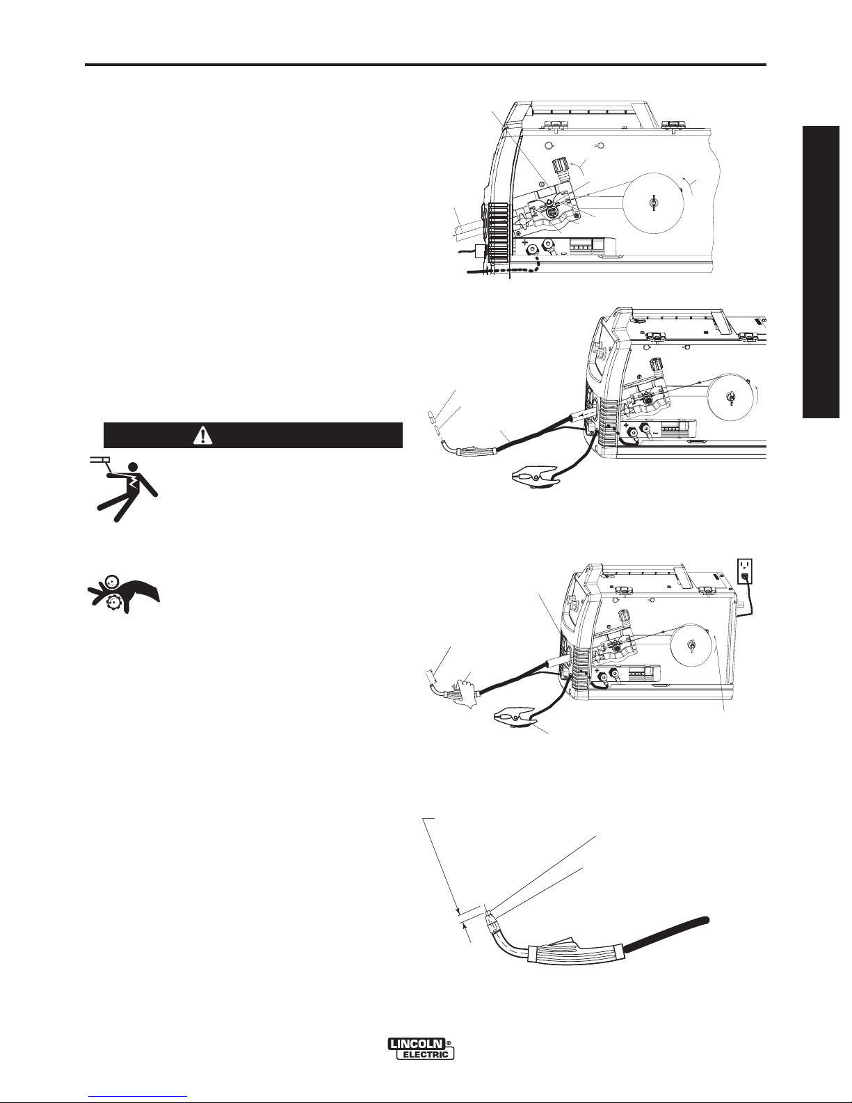
B. CONNECT LEADS AND CABLES ON
THE MACHINE
(See Figure B.7)
1. Open the case side door
2. Slide the connector end of the gun and cable
through the hole in the machine front and into the
gun connector bushing on the wire drive.
3. Make sure the gun connector end is seated fully
into the wire drive and tighten the molded hand
screw to secure the gun connector.
4. Plug the gun trigger lead connector into the 4 pin
gun trigger receptacle on the machine front.
5. Wire Drive Polarity. Flux cored welding requires
negative (-) polarity. Connect the short power
cable from the wire drive to the negative (-) output
terminal and tighten threaded knob.
6. Work Lead Connection. Slide the lugged end of
the work cable through the hole in the machine
front and place on the positive (+) output terminal
and tighten threaded knob.
SLIDE
C
ONNEC
END
H
ERE
TOR
(4 PIN)
L
EAD CO
GUN AND CABLE
TERMINAL END
(FITS ON STUD INSIDE
SEE FIGURE BELOW)
NNECTOR
MOLDED HAND SCREW TO
TIGHTEN CONNECTOR
BUSHING
CO
NNECTOR
END ATTACH
(4 PIN)
TRIGGER RE
PLUGGED IN
WORK CLAMP
CEPTACLE
FIGURE B.7
OPEN LATCH DOO
WORK CLAMP
R
ALL COMPONENTS SHOWN CONNECTED
(FRONT AND SIDE DOOR IS REMOVED
FOR CLARITY)
SHORT POWER
CABLE NEGATIVE "-"
OUTPUT TERMINAL
WORK LEAD
CONNECTION
POSITIVE "+"
OUTPUT TERMINAL
C. LOAD WIRE SPOOL
(See Figure B.8)
1. Locate the blue labeled 4" diameter spool of .035
NR-211MP flux-cored wire and place onto wire
spool spindle. Orient the spool so that the wire
feeds off the top of the spool.
2. Secure spool in place by tightening the wing nut
against the against the spacer that holds the wire
spool on the spindle.
3. Open the pivot arm assembly by rotating the tension arm assembly down and lift pivot arm assembly up.
4. Remove drive roll
the drive roll on. Install the .030/.045 knurled drive
roll.
5. Carefully unwind and straighten the first six inches of
welding wire from the spool. Do not let the end of the
wire go to prevent the wire from unspooling.
by turning the twist lock that holds
FIGURE B.8
PIVOT ARM ASSEMBLY
BEARING
OUTGOING GUIDE
TENSION ARM ASSEMBLY DOWN
LINER
TWIST LOCK
DRIVE ROLL
WIRE SPOOL
.035" (0.9mm)
NR-211-MP
WIRE FEEDER WELDERS (125, 140, 180 MODELS)
Page 15
B-6
OPERATION
(See Figure B.9)
6. Feed the wire through the inlet liner, over the
drive roll groove, thru the outgoing guide and
wire drive outlet on the gun side.
7. Close the Pivot Arm Assembly and secure by pivoting the Tension Arm Assembly back to the up
position.
(See Figure B.10)
8. Remove the nozzle from the gun and contact tip
and straighten the gun out flat.
PIVOT ARM ASSEMBLY
WITH BEARING PRESSING
AGAINST DRIVE ROLL
SLIDE WIRE
INTO GUN
CONNECTOR
SIDE
FIGURE B.9
TENSION ARM ASSEMBLY
LOCKED IN UP POSITION
BEARING
LINER
DRIVE ROLL
OUTGOING GUIDE
WIRE SPOOL
.035" (0.9mm)
NR-211-MP
DIRECTION
OF WIRE
B-6
9. Turn the machine power to on and depress the
gun trigger to feed the wire through the gun liner
until the wire comes out of the threaded end of
the gun several inches. (See figure B.11)
10. When trigger is released spool of wire should not
unwind. Adjust wire spool brake accordingly.
WARNING
MOVING PARTS AND ELECTRICAL
CONTACT CAN CAUSE INJURY OR BE
FATAL.
•When the gun trigger is depressed
drive rolls, spool of wire and electrode are ELECTRICALLY LIVE (HOT).
• Keep away from moving parts and
pinch points.
• Keep all Doors, Covers, panels and
guards securely in place.
DO NOT REMOVE OR CONCEAL
WARNING LABELS.
------------------------------------------------------------------------
11. Install the .035 contact tip
12. Install the black flux cored welding nozzle to the
gun.
REMOVED NOZZLE
REMOVED CONTACT TIP
LAY CABLE AND GUN STRAIGHTEN
IN THIS POSITION
FEED WIRE
APPROXIMATELY 4.00"
FROM THE GUN TUBE END
DEPRESS TRIGGER
TO ACTIVATE WIRE,
WHICH FEEDS THE WIRE
THRU THE LINER.
FIGURE B.10
FIGURE B.11
ON/OFF
SWITCH
WORK CLAMP AND CABLE
.035"(0.9mm)
NR-211-MP
WIRE SPOOL
.035"(0.9mm)
NR-211-MP
WIRE SPOOL
PLUG IN POWER
INPUT CORD
ROTAT ION
OPERATOR’S MANUAL
13. Trim the wire stickout to 3/8” from the contact tip.
(See Figure B.12)
14. Close the case side door. The machine is now
ready to weld.
15. Read "Learn to Weld" (LTW1) that is included
with the machine or watch the "How to Weld"
DVD included with the machine.
16. Based on the thickness of the material you are
going to weld and the type and diameter of the
welding wire set the voltage and the wire feed
speed per the procedure decal attached to the
inside of the wire drive compartment door.
WIRE FEEDER WELDERS (125, 140, 180 MODELS)
TRIM WIRE
STICKOUT
3/8"(9.5mm)
from the Contact Tip
FIGURE B.12
INSTALL .035 CONTACT TIP
INSTALL BLACK FLUX-CORED NOZZLE
Page 16
B-7
OPERATION
SETTING UP AND MAKING A MIG WELD*
B-7
A. ITEMS NEEDED FOR MIG WELDING
1. 025 Contact Tip
.025
3. .025 Drive Roll
.025
4. .025 SuperArc L-56 Solid MIG Wire
L-56 MIG
7. Work Cable & Clamp
8. Gas Regulator & Gas Line
9. Bottle of 75/25 Ar/
CO2shielding gas (or 100%
shielding gas) (note this requires a
adapter which is sold separately.
CO
CO2regulator
2
5. Brass gun nozzle
6. Welding Gun
WIRE
MALE END
CO
2
100%
(REQUIRES ADAPTER
SOLD SEPARATELY)
FEMALE END
75/25
MIXES
* 125 Amp Units can be upgraded for MIG welding
using KIT K2526-1 (See Accessory Section).
WIRE FEEDER WELDERS (125, 140, 180 MODELS)
Page 17
B-8
B. INSTALL SHIELDING GAS
OPERATION
B-8
FIGURE B.13
MIG welding requires an appropriate bottle of shielding
gas. For mild steel either a cylinder bottle of Ar/CO
100% CO
can be used refer to the following instruc-
2
or
2
tions to properly connect shielding gas to the machine.
WARNING
CYLINDER may explode if damaged. Keep cylinder upright and
chained to support
• Keep cylinder away from areas
where it may be damaged.
• Never lift welder with cylinder
attached.
• Never allow welding electrode to
touch cylinder.
• Keep cylinder away from welding
or other live electrical circuits.
-----------------------------------------------------------------------
WARNING
BUILDUP OF SHIELDING GAS may
harm health or kill.
• Shut off shielding gas supply
when not in use.
MALE END
CO
100%
FEMALE END
75/25
MIXES
2
REGULATOR
ADAPTER
PLASTIC
WASHER
S19298
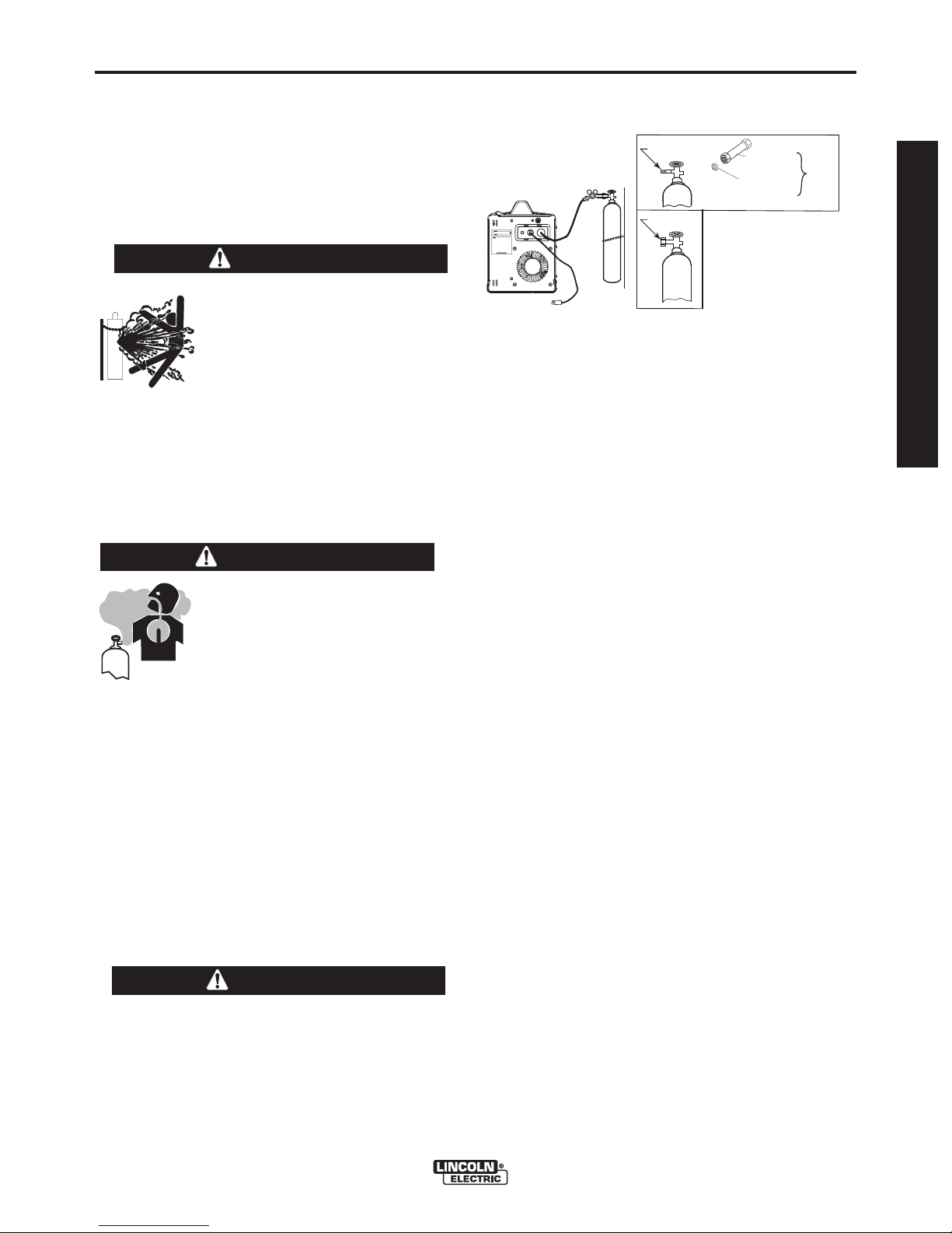
3. Attach the flow regulator to the cylinder valve and
tighten the union nut securely with a wrench.
NOTE: If connecting to 100%
CO2cylinder, a
CO
2
regulator adapter is required. Purchase separately
S19298
CO2adapter be sure to install plastic washer
included in the fitting on the bottle side.(See Figure
B.13 )
4. Refer to Figure B.13. Attach one end of inlet gas hose
to the outlet fitting of the flow regulator and tighten the
union nut securely with a wrench. Connect the other
end to the machine Solenoid Inlet Fitting (5/8-18
female threads — for CGA — 032 fitting). Make certain the gas hose is not kinked or twisted.
SHIELDING GAS
OPERATOR’S MANUAL
1. Secure the cylinder to a wall or other stationary
support to prevent the cylinder from falling over.
Insulate the cylinder from the work circuit and earth
ground. Refer to Figure B.13.
2. With the cylinder securely installed, remove the
cylinder cap. Stand to one side away from the outlet and open the cylinder valve very slightly for an
instant. This blows away any dust or dirt which may
have accumulated in the valve outlet.
WARNING
BE SURE TO KEEP YOUR FACE AWAY FROM
THE VALVE OUTLET WHEN “CRACKING” THE
VALVE. Never stand directly in front of or behind
the flow regulator when opening the cylinder
valve. Always stand to one side.
------------------------------------------------------------------------
WIRE FEEDER WELDERS (125, 140, 180 MODELS)
1. For
CO2, open the cylinder very slowly. For argonmixed gas, open cylinder valve slowly a fraction of a
turn. When the cylinder pressure gauge pointer stops
moving, open the valve fully.
2. Set gas flow rate for 30 to 40 cubic feet per hour (14
to 18 I/min.) under normal conditions, increase to as
high as 40 to 50 CFH (18 to 23.5 I/min.) under drafty
(slightly windy) conditions.
3. Keep the cylinder valve closed, except when using
the machine.
Page 18
B-9
OPERATION
C. CONNECT LEADS AND CABLES ON
THE MACHINE
(See Figure B.14)
1. Open the case side door.
2. Slide the connector end of the gun and cable
through the hole of the machine front and into the
gun connector bushing on the wire drive.
3. Make sure the gun connector end is seated fully
into the wire drive and tighten the thumbscrew to
secure the gun.
4. Plug the gun trigger lead connector into the 4 pin
gun trigger receptacle on the machine front.
5. Wire Drive Polarity. MIG welding requires Positive
(+) polarity. Connect the short power cable from
the wire drive to the positive (+) output terminal and
tighten the thumbscrew.
LOCATE COMPONENTS
TO CONNECT TO THE
FRONT OF MACHINE
SLIDE
CONNECTOR
END HERE
(4 PI
N)
LEA
D CON
GUN A
FIGURE B.14
TERMINAL EN
(FITS ON STUD
S
EE FIGURE B
NE
CTOR
ND CABLE
MOLDED HAND SCREW TO
TIGHTEN CONNECTOR
BUSHING
WORK CLAMP
OPEN LATCH DOOR
D
I
NSI
DE
E
LOW)
B-9
CASE SIDE DOOR
ALL COMPONENTS SHOWN CONNECTED
(FRONT AND SIDE DOOR IS REMOVED
FOR CLARITY)
WORK LEAD
CONNECTION
NEGATIVE "-"
OUTPUT TERMINAL
6. Work Lead Connection. Slide the lugged end of the
work cable through the hole in the machine front
and place on the negative (-) output terminal and
tighten thumbscrew.
D. LOAD WIRE SPOOL
(See Figure B.15)
1. Locate the green labeled 4" diameter spool of .025
L-56 solid MIG wire and place onto wire spool spindle. Orient the spool so that the wire feeds off the
top of the spool.
2. Secure spool in place by tightening the wing nut
against the against the spacer that holds the wire
spool on the spindle.
3. Open the pivot arm assembly by rotating the tension arm assembly down and lift pivot arm assembly up.
4. Remove drive roll
the drive roll on. Install the
grooved
drive roll.
by turning the twist lock that holds
.025-.035 smooth
CONNECTOR
END ATTACH
(4 PIN)
T
RIGGER RECEPTACL
PLUGGED IN
FIGURE B.15
PIVOT ARM ASSEMBLY
BEARING
OUTGOING GUIDE
TENSION ARM ASSEMBLY DOWN
LINER
TWIST LOCK
E
WORK CLAMP
WIRE SPOOL
.025" (0.6mm)
L
-
5
6
S
I
O
L
I
M
D
SHORT POWER
CABLE POSITIVE "+"
OUTPUT TERMINAL
G
5. Carefully unwind and straighten the first six inches
of welding wire from the spool. Do not let the end
of the wire go to prevent the wire from unspooling.
WIRE FEEDER WELDERS (125, 140, 180 MODELS)
DRIVE ROLL
Page 19

B-10
OPERATION
(See Figure B.16)
6. Feed the wire through the inlet liner, over the drive
roll groove, thru the outgoing guide and wire drive
outlet on the gun side.
PIVOT ARM ASSEMBLY
WITH BEARING PRESSING
AGAINST DRIVE ROLL
B-10
FIGURE B.16
7. Close the Pivot Arm Assembly and secure by pivoting the Tension Arm Assembly back to the up
position.
(See Figure B.17)
8. Remove the nozzle from the gun and contact tip
and straighten the gun out flat.
9. Turn the machine power to on and depress the
gun trigger to feed the wire through the gun liner
until the wire comes out of the threaded end of the
gun several inches. (See Figure B.18)
10. When trigger is released spool of wire should not
unwind. Adjust wire spool brake accordingly.
WARNING
MOVING PARTS AND ELECTRICAL
CONTACT CAN CAUSE INJURY OR BE
FATAL.
•When the gun trigger is depressed
drive rolls, spool of wire and electrode
are ELECTRICALLY LIVE (HOT).
• Keep away from moving parts and
pinch points.
• Keep all Doors, Covers, panels and
guards securely in place.
DO NOT REMOVE OR CONCEAL
WARNING LABELS.
-----------------------------------------------------------------------
11. Install the .025 contact tip.
12. Install the brass gas MIG welding nozzle to the
gun.
13. Trim the wire stickout to 3/8 from the nozzle end.
(See Figure B.19)
SLIDE WIRE
INTO GUN
CONNECTOR
SIDE
REMOVED NOZZLE
REMOVED CONTACT TIP
LAY CABLE AND GUN STRAIGHTEN
IN THIS POSITION
FEED WIRE
APPROXIMATELY 4.00"
FROM THE GUN TUBE END
DEPRESS TRIGGER
TO ACTIVATE WIRE,
WHICH FEEDS THE WIRE
THRU THE LINER.
OUTGOING GUIDE
FIGURE B.17
FIGURE B.18
ON/OFF
SWITCH
WORK CLAMP AND CABLE
TENSION ARM ASSEMBLY
LOCKED IN UP POSITION
BEARING
LINER
DRIVE ROLL
WIRE SPOOL
.025" (0.6mm)
L
-
5
6
S
O
L
WIRE SPOOL
.025" (0.6mm)
L
-
5
6
S
O
L
I
D
I
D
M
M
G
I
G
I
ROTAT ION
DIRECTION
OF WIRE
WIRE SPOOL
.025" (0.6mm)
L
-
5
6
S
O
PLUG IN POWER
INPUT CORD
OPERATOR’S MANUAL
G
I
M
D
L
I
14. Close the case side door. The machine is now
ready to weld.
15. Read "Learn to Weld" (LTW1) that is included with
the machine or watch the "How to Weld" DVD
included with the machine.
16. Based on the thickness of the material you are
going to weld and the type and diameter of the
welding wire set the voltage and the wire feed
speed per the procedure decal attached to the
inside of the wire drive compartment door.
WIRE FEEDER WELDERS (125, 140, 180 MODELS)
TRIM WIRE
STICKOUT
3/8"(9.5mm)
from the Brass Nozzle
FIGURE B.19
INSTALL .025 CONTACT TIP
INSTALL BRASS NOZZLE
Page 20

B-11
OPERATION
SETTING UP AND MAKING A ALUMINUM WELD USING SPOOL GUN
1. Follow the MIG welding steps in the previous section.
2. Connect a bottle of 100% Argon shielding Gas per
previous section.
3. Disconnect Magnum 100L Gun.
4. Install optional K2532-1 Magnum 100SG spool gun
per instructions included with gun.
5. Set Gun selector toggle switch to Spool Gun position. (See Figure B.20)
FIGURE B.20
B-11
WARNING
6. Turn machine on and make weld per recommended
settings on Procedure Decal inside machine door.
WIRE FEEDER WELDERS (125, 140, 180 MODELS)
Page 21

C-1
K2525-1 - Spot Timer Kit
Timer kit, when turned on, allows you to set a fixed
weld time so that when the gun trigger is pulled the
machine will weld for a fixed time period up to 10 seconds. Ideal for making consistent spot welds when
welding on thin sheet metal
K2528-1 - 045 Innershield Kit (For 230V models)
Includes everything needed to weld with .045 diameter Innershield wire. Includes an .035/.045
Magnum™ 100L gun liner, .045 Contact Tip, gasless
nozzle, knurled drive roll, .035-.045 inner wire guide,
and a 10 lb. (4.5kg) spool of .045"(0.9mm)
Innershield® NR®-212 wire.
K2532-1 - Magnum 100SG Spool Gun
Designed to easily feed small 4" diameter (1lb. spools
of) .030 or .035 aluminum wire. Includes gun, adapter
kit, three extra .035 contact tips, gas nozzle, and
spool of Superglaze 4043 .035" diameter welding
wire. Packaged in a convenient carry case.
ACCESSORIES
C-1
OPERATOR’S MANUAL
K2377-1 - Small Canvas Cover
Protect your machine when not in use. Made from
attractive red canvas that is flame retardant, mildew
resistant and water repellent. Includes a convenient
side pocket to hold welding gun.
For additional Optional and Miscellaneous Parts
(See Parts Pages)
WIRE FEEDER WELDERS (125, 140, 180 MODELS)
Page 22
C-2
ACCESSORIES
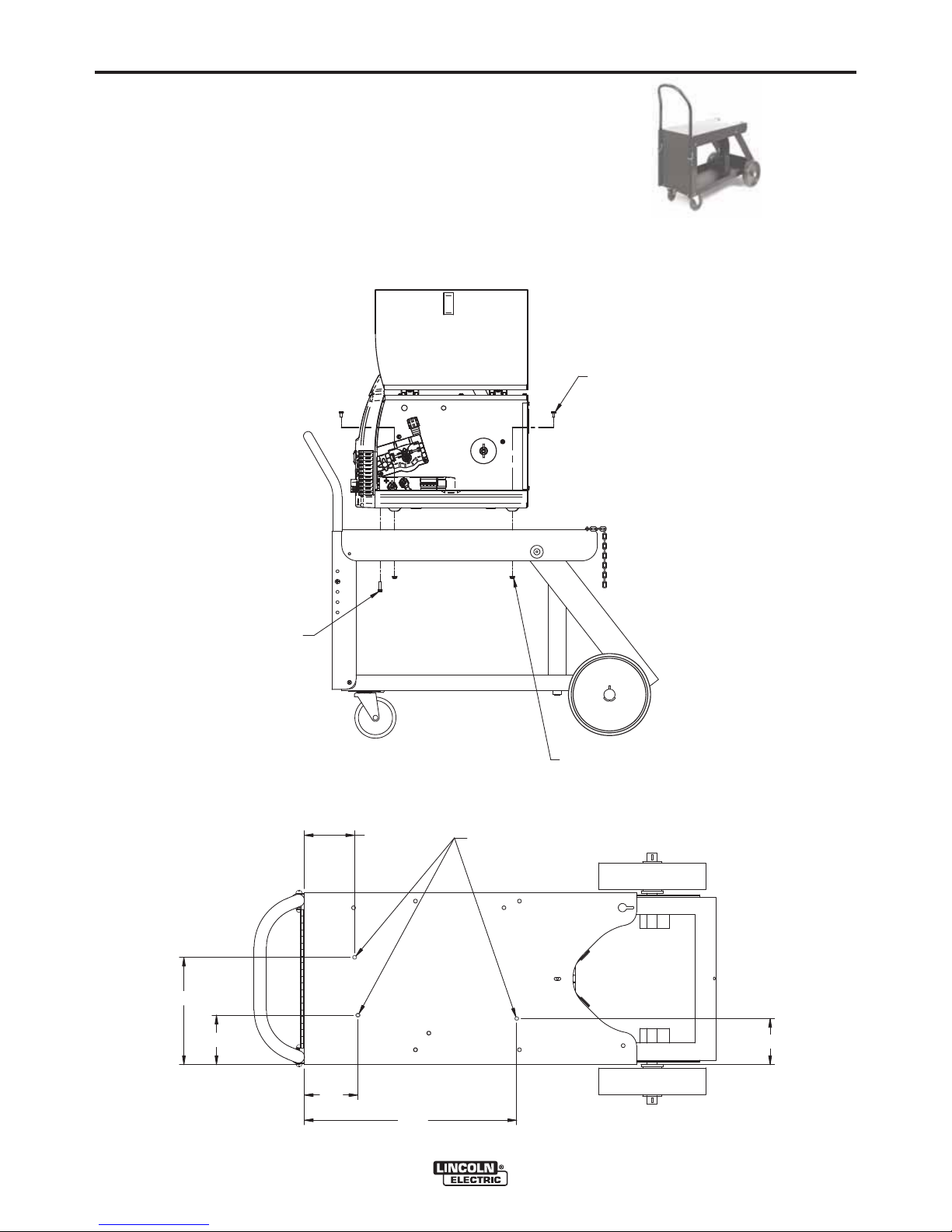
K520—Utility Cart
Heavy duty cart stores and transports welder, 150
cubic foot shielding gas cylinder, welding cables and
accessories. Includes stable platforms for welder and
gas bottle platform, lower tray for added storage
capacity and adjustable height handle.
For mounting welding machines to K520 carts that do not have slotted mounting holes.
Drill 9/32” holes (3 places) into the cart top as shown and attach the welding machine to the
cart with the proper hardware shown.
C-2
1/4"-20 X 1/2" Hex Head Cap Screw
(2 Required)
1/4"-20 X 1"
Thread Forming Screw
(1 Required)
8-1/16"
3-11/16"
3-3/4"
1/4"-20 X 1/2" Hex Head Cap Screw
(2 Required)
9/32" DRILL
3 PLACES
3-13/32"
WIRE FEEDER WELDERS (125, 140, 180 MODELS)
4"
16"
Page 23
C-3
ACCESSORIES
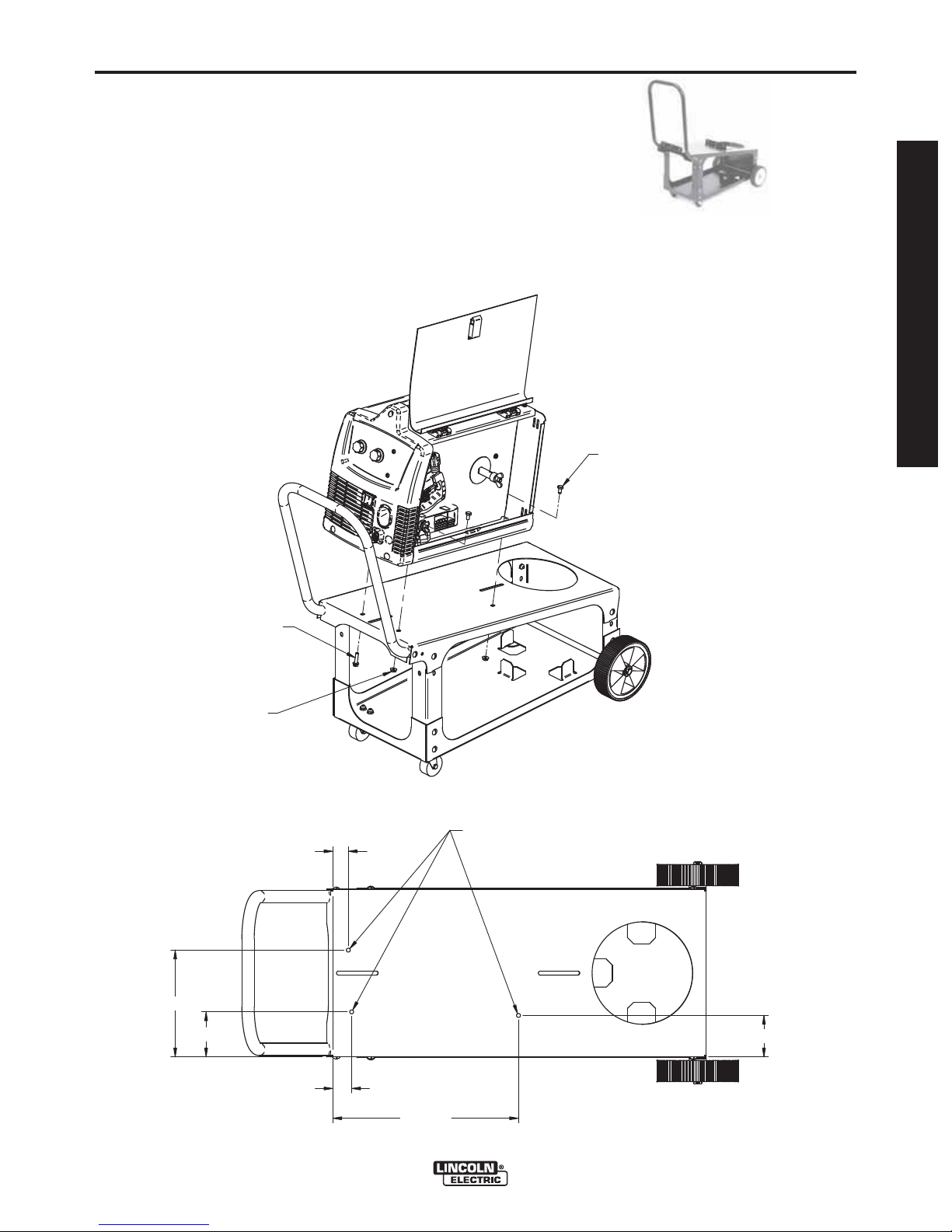
K2275-1 - Welding Cart
Lightweight cart stores and transports welder, 80
cubic foot shielding gas cylinder, welding cables and
accessories. Includes an angled top shelf for easy
access to controls, lower tray for added storage
capacity, a sturdy fixed handle and convenient cable
wrap hanger.
For mounting welding machines to K2275-1 carts that do not have slotted mounting holes.
Drill 9/32” holes (3 places) into the cart top as shown and attach the welding machine to the
cart with the proper hardware shown.
C-3
OPERATOR’S MANUAL
1/4"-20 X 1/2" Hex Head Cap Screw
(2 Required)
1/4"-20 X 1"
Thread Forming Screw
(1 Required)
1/4"-20 Flange Nut
(2 Required)
7-9/16"
3-3/16"
1-1/4"
9/32" DRILL
3 PLACES
2-15/16"
WIRE FEEDER WELDERS (125, 140, 180 MODELS)
1-1/2"
13-1/2"
Page 24

D-1
MAINTENANCE
D-1
MAINTENANCE
SAFETY PRECAUTIONS
WARNING
ELECTRIC SHOCK can kill.
• Disconnect input power by removing plug from receptacle before
working inside WIRE FEEDER
WELDERS (125,140, 180 MODELS).
Use only grounded receptacle. Do not touch electrically “hot” parts inside WIRE FEEDER
WELDERS (125,140, 180 MODELS).
• Have qualified personnel do the maintenance
and trouble shooting work.
-----------------------------------------------------------------------
ROUTINE MAINTENANCE
POWER SOURCE COMPARTMENT
No user serviceable parts inside! Do not attempt to
perform service in the power source (fixed) side of the
WIRE FEEDER WELDERS (125,140, 180 MODELS).
Take the unit to an authorized Lincoln Service Center
if you experience problems. N O maintenance is
required.
In extremely dusty locations,
sages causing the welder to run hot with premature
tripping of thermal protection. If so, blow dirt out of the
welder with low pressure air at regular intervals to
eliminate excessive dirt and dust build-up on internal
parts.
WIRE FEED COMPARTMENT
1. When necessary, vacuum accumulated dirt from
gearbox and wire feed section.
2. Occasionally inspect the incoming guide tube and
clean inside diameter if necessary.
3. Motor and gearbox have lifetime lubrication and
require no maintenance.
FAN MOTOR
Has lifetime lubrication — requires no maintenance.
WIRE REEL SPINDLE
Requires no maintenance. Do not lubricate shaft.
dirt may clog the air pas-
GUN AND CABLE MAINTENANCE
FOR MAGNUM™ 100L GUN
Gun Cable Cleaning
Clean cable liner after using approximately 300 lbs
(136 kg) of solid wire or 50 lbs (23 kg) of flux-cored
wire. Remove the cable from the wire feeder and lay it
out straight on the floor. Remove the contact tip from
the gun. Using low pressure air,
cable liner from the gas diffuser end.
gently blow out the
CAUTION
Excessive pressure at the start may cause the dirt
to form a plug.
Flex the cable over its entire length and again blow
out the cable. Repeat this procedure until no further
dirt comes out.
Contact Tips, Nozzles, and Gun Tubes
1. Dirt can accumulate in the contact tip hole and
restrict wire feeding. After each
used, remove the contact tip and clean it by pushing a short piece of wire through the tip repeatedly.
Use the wire as a reamer to remove dirt that may
be adhering to the wall of the hole through the tip.
2. Replace worn contact tips as required.
or “hunting” arc is a typical symptom of a worn contact tip. To install a new tip, choose the correct size
contact tip for the electrode being used (wire size is
stenciled on the side of the contact tip) and screw it
snugly into the
3. Remove spatter from inside of gas nozzle and from
tip after each 10 minutes of arc time or as required.
4. Be sure the gas nozzle is fully screwed onto the
diffuser for gas shielded processes. For the
Innershield®process, the gasless nozzle should
screw
onto the diffuser.
5. To remove gun tube from gun, remove gas nozzle
or gasless nozzle and remove diffuser from gun
tube. Remove both collars from each end of the
gun handle and separate the handle halves.
Loosen the locking nut holding the gun tube in
place
against the gun end cab le connector.
Unscrew gun tube from cable connector. To install
gun tube, screw the locking nut on the gun tube as
far as possible. Then screw the gun tube into the
cable connector until it bottoms. Then unscrew
more than one turn) the gun tube until its axis is
perpendicular to the flat sides of the cable connector and pointed in the direction of the trigger.
Tighten the locking nut so as to maintain the proper
relationship between the gun tube and the cable
connector.
fuser. Replace the gas nozzle or gasless nozzle.
gas diffuser.
Replace the gun handle, trigger and dif-
spool of wire is
A variable
(no
WIRE FEEDER WELDERS (125, 140, 180 MODELS)
Page 25
D-2
MAINTENANCE
OVERLOAD PROTECTION
Output Overload
The WIRE FEEDER WELDERS (125,140, 180 MODELS) is equipped with a circuit breaker and a thermostat which protects the machine from damage if maximum output is exceeded. The circuit breaker button
will extend out when tripped. The circuit breaker must
be manually reset.
Thermal Protection
The WIRE
ELS) has a rated output duty cycle as defined in the
Technical Specification page. If the duty cycle is
exceeded, a thermal protector will shut off the output
until the machine cools to a reasonable operating temperature. This is an automatic f
FEEDER WELDERS (125,140, 180 MODELS) and
does not require user intervention. The fan continues
to run during cooling.
Electronic Wire Drive Motor Protection
The WIRE FEEDER WELDERS (125,140, 180 MODELS) has built-in protection for wire drive motor overload.
FEEDER WELDERS (125,140, 180 MOD-
unction of the WIRE
Set Screw Brass Cable
Connector
Liner Assembly
(Liner bushing to be sealed tight
against brass cable connector)
FIGURE D.2
Liner trim length
D-2
1-1/4”(31.8 mm)
Liner Trim Length
Gas Diffuser
Gas Nozzle or
Gasless Nozzle
OPERATOR’S MANUAL
CHANGING LINER
NOTICE: The variation in cable lengths prevents the
interchangeability of liners. Once a liner has been cut
for a particular gun, it should not be installed in another gun unless it can meet the liner cutoff length
requirement. Refer to Figure D.2.
1. Remove the gas nozzle from
ing counter-clockwise.
2. Remove the existing contact tip from the gun by
unscrewing counter-clockwise.
3. Remove the gas diffuser from the gun tube by
unscrewing counter-clockwise.
4. Lay the gun and cable out straight on a flat surface.
Loosen the set screw located in the brass connector
at the wire feeder end of the cable. Pull the liner
out of the cable.
5. Insert a new untrimmed liner into the connector end
of the cable. Be sure the liner bushing is stenciled
appropriately for the wire size being used.
6. Fully seat the liner bushing into the connector.
Tighten
At this time, the gas diffuser should not be installed
onto the end of the gun tube.
the set screw on the brass cable connector.
the gun by unscrew-
8. Screw the gas diffuser onto the end of the gun tube
and securely tighten.
9. Replace the contact tip and nozzle.
GUN HANDLE PARTS
The gun handle consists of two halves that are held
together with a collar on each end. To open up the
handle, turn the collars approximately 60 degrees
counter-clockwise until the collar reaches a stop. Then
pull the collar off the gun handle. If the collars are difficult to turn,
place a screwdriver against the tab on the collar and
give the screwdriver a sharp blow to turn the collar
past an internal locking rib. See Figure D-3.
position the gun handle against a corner,
➣
Counter-clockwise
7. With the gas nozzle and diffuser removed from the
gun tube, be sure the cable is straight, and then
trim
the liner to the length shown in the Figure D.2.
Remove any burrs from the end of the liner.
WIRE FEEDER WELDERS (125, 140, 180 MODELS)
FIGURE D.3
Page 26

E-1
TROUBLESHOOTING
HOW TO USE TROUBLESHOOTING GUIDE
WARNING
Service and Repair should only be performed by Lincoln Electric Factory Trained Personnel.
Unauthorized repairs performed on this equipment may result in danger to the technician and
machine operator and will invalidate your factory warranty. For your safety and to avoid Electrical
Shock, please observe all sa
__________________________________________________________________________
fety notes and precautions detailed throughout this manual.
E-1
This Troubleshooting Guide is provided to help you
locate and repair possible machine malfunctions.
Simply follow the three-step procedure listed below.
Step 1. LOCATE PROBLEM (SYMPTOM).
Look under the column labeled “PROBLEM (SYMPTOMS)”. This column describes possible symptoms
that the machine may exhibit. Find the listing
best describes the symptom that the machine is
exhibiting.
Step 2. POSSIBLE CAUSE.
The second column labeled “POSSIBLE CAUSE” lists
the obvious external possibilities that may contribute
to the machine symptom.
that
Step 3. RECOMMENDED COURSE OF ACTION
This column provides a course of action for the
Possible Cause, generally it states to contact your
local Lincoln Authorized Field Service Facility.
If you do not understand or are unable to perform the
Recommended Course of Action safely, contact your
local Lincoln Authorized Field Service
Facility.
If for any reason you do not understand the test procedures or are unable to perform the tests/repairs safely, contact your
Local Lincoln Authorized Field Service Facility for technical troubleshooting assistance before you proceed.
WIRE FEEDER WELDERS (125, 140, 180 MODELS)
CAUTION
Page 27

E-2
TROUBLESHOOTING
Observe all Safety Guidelines detailed throughout this manual
E-2
PROBLEMS
(SYMPTOMS)
Major physical or electrical damage
is evident.
No wire feed, weld output or gas
flow when gun trigger is pulled. Fan
does NOT operate.
No wire feed, weld output or gas
flow when gun trigger is pulled.
Fan operates normally.
POSSIBLE
CAUSE
OUTPUT PROBLEMS
“Do not Plug in machine or turn it on”.
Contact your local Authorized Field
Service Facility.
1. Make sure correct voltage is
applied to the machine.
2. Make certain that power switch
is in the ON position.
3. Make sure circuit breaker is
reset.
1. The thermostat may be tripped
due to overheating. Let machine
cool. Weld at lower dut
2. Check for obstructions in air
flow. Check Gun Trigger connections. See Installation section.
y cycle.
RECOMMENDED
COURSE OF ACTION
If all recommended possible areas
of misadj ustment have been
checked and the problem persists,
Contact your local Lincoln
Authorized Field Service
Facility.
OPERATOR’S MANUAL
PROBLEMS
(SYMPTOMS)
No wire feed when gun trigger is
pulled. Fan runs, gas flows and
machine has correct open circuit
voltage (33V) – weld output.
3. Gun trigger may be faulty.
POSSIBLE
CAUSE
FEEDING PROBLEMS
1. If the wire drive motor is running
make sure that the correct drive
rolls are installed in the machine.
2. Check for clogged cable liner or
contact tip.
3. Check for proper size cable liner
and contact tip.
RECOMMENDED
COURSE OF ACTION
If all recommended possible areas
of misadj ustment have been
checked and the problem persists,
Contact your local Lincoln
Authorized Field Service
Facility.
If for any reason you do not understand the test procedures or are unable to perform the tests/repairs safely, contact your
Local Lincoln Authorized Field Service Facility for technical troubleshooting assistance before you proceed.
WIRE FEEDER WELDERS (125, 140, 180 MODELS)
CAUTION
Page 28

E-3
TROUBLESHOOTING
Observe all Safety Guidelines detailed throughout this manual
E-3
PROBLEMS
(SYMPTOMS)
Low or no gas flow when gun
trigger is pulled. Wire feed, weld
output and fan operate normally.
PROBLEMS
(SYMPTOMS)
Arc is unstable – Poor starting
POSSIBLE
CAUSE
GAS FLOW PROBLEMS
1. Check gas supply, flow regulator
and gas hoses.
2. Check gun connection to
machine for obstruction or leaky
seals.
POSSIBLE
CAUSE
WELDING PROBLEMS
1. Check for correct input voltage
to machine.
RECOMMENDED
COURSE OF ACTION
If all recommended possible areas
of misadj ustment have been
checked and the problem persists,
Contact your local Lincoln
Authorized Field Service
Facility.
RECOMMENDED
COURSE OF ACTION
2. Check for proper electrode
polarity for process.
3. Check gun tip for wear or damage and proper size – Replace.
4. Check for proper gas and flow
rate for process. (For MIG only.)
5. Check work cable for loose or
faulty connections.
6. Check gun for damage or
s.
break
7. Check for proper drive roll orientation and alignment.
8. Check liner for proper size.
If all recommended possible areas
of misadj ustment have been
checked and the problem persists,
Contact your local Lincoln
Authorized Field Service
Facility.
If for any reason you do not understand the test procedures or are unable to perform the tests/repairs safely, contact your
Local Lincoln Authorized Field Service Facility for technical troubleshooting assistance before you proceed.
WIRE FEEDER WELDERS (125, 140, 180 MODELS)
CAUTION
Page 29

F-1
DIAGRAMS
F-1
OPERATOR’S MANUAL
NOTE: This diagram is for reference only. It may not be accurate for all machines covered by this manual. The
specific diagram for a particular code is pasted inside the machine on one of the enclosure panels.
WIRE FEEDER WELDERS (125, 140, 180 MODELS)
Page 30

F-2
DIMENSION PRINT
F-2
WIRE FEEDER WELDERS (125, 140, 180 MODELS)
Page 31

NOTES
OPERATOR’S MANUAL
WIRE FEEDER WELDERS (125, 140, 180 MODELS)
Page 32

ALIMENTADOR DE ALAMBRE
IMS891-C
SOLDADORA (MODELOS 125, 140, 180)
Enero, 2009
Para usarse con máquinas con Números de Código:
TABLA DE CONTENIDO
Instalación ...........................Sección A
Especificaciones Técnicas .................A-1,A-2
Precauciones de Seguridad ....................A-2
Selección de una Ubicación Adecuada .........A-2
Estibación ................................A-2
Inclinación................................A-2
Identificación y Ubicación de los Componentes
for180Ampand140AmpUnits...............A-3
Identificación y Ubicación de los Componentes
for125AmpFluxCoreUnit ..................A-3
Operación ...........................Sección B
Seguridad y Descripción del Producto ............B-1
Controles y Configuraciones ...............B-2,B-3
Rodillo Impulsor y Tabla de Guías de Alambre .....B-4
Preparación y Realización de una
Soldadura deAlambre Tubular ...........B-4 aB-6
Preparación y Realización de una Soldadura
MIGeInstalacióndelGasProtector ......B-7aB-10
Preparación y Realización de una Soldadura de Aluminio
. .B-11..
11173 por 11506, 11550
ISO 9001
ANSI RAB
QMS
Designed and Manufactured Under aI
Quality Program Certified byI
ABS Quality Evaluations, Inc.I
to ISO 9001 Requirements.
CERTIFICATE NUMBER: 30273
Accesorios ..........................
Accesorios Opcionales .......................C-1
Carros Utilitarios ........................C-2,C-3
Mantenimiento .......................Sección
Precauciones de Seguridad ...................D-1
Compartimiento de Alimentación de Alambre,
Motor del Ventilador, Mantenimiento del Carrete de
Alambre ................................D-1
Mantenimiento de la Pistola y Cable .............D-2
Protección contra Sobrecarga ..................D-2
Procedimientos de Reemplazo de Componentes . . .D-2
LocalizacióndeAverías ................Sección E
Precauciones de Seguridad ....................E-1
Cómo Utilizar la Guía de Localización de Averías . . .E-1
Guía de Localización de Averías ...........E-2aE-3
D
iagrama de Cableado & Dibujo de Dimensi
Sección C
ón.
.Sección F
.
La Seguridad Depende de
D
El equipo de soldadura de arco y corte
de Lincoln está diseñado y construido
teniendo la seguridad en mente. Sin
embargo, es posible aumentar su
seguridad general a través de una
instalación apropiada... y una
operación cuidadosa de su parte. NO
INSTALE, OPERE O REPARE ESTE
EQUIPO SIN LEER ESTE MANUAL Y
LAS PRECAUCIONES DE SEGURIDAD CONTENIDAS EN EL MISMO. Y
lo más importante, piense antes de
actuar y tenga cuidado.
Usted
MANUAL DE OPERACIÓN
Copyright © Lincoln Global Inc.
• Ventas y Servicio a través de las Subsidiarias y Distribuidores en todo el Mundo •
Cleveland, Ohio 44117-1199 U.S.A. TEL: 216.481.8100 FAX: 216.486.1751 WEB SITE: www.lincolnelectric.com
•Líder mundial en productos de soldadura y corte •
Page 33

i-SP
SEGURIDAD
ADVERTENCIA
ADVERTENCIA DE LA LEY 65 DE CALIFORNIA
En el estado de California, se considera a las emisiones
del motor de diesel y algunos de sus componentes
como dañinas para la salud, ya que provocan cáncer,
defectos de nacimiento y otros daños reproductivos.
i-SP
Las emisiones de este tipo de productos contienen
químicos que, para el estado de California, provocan
cáncer, defectos de nacimiento y otros daños
reproductivos.
Lo anterior aplica a los motores Diesel
Lo anterior aplica a los motores de gasolina
LA SOLDADURA AL ARCO PUEDE SER PELIGROSA. PROTEJASE USTED Y A LOS DEMAS CONTRA
POSIBLES LESIONES DE DIFERENTE GRAVEDAD, INCLUSO MORTALES. NO PERMITA QUE LOS NIÑOS
SE ACERQUEN AL EQUIPO. LAS PERSONAS CON MARCAPASOS DEBEN CONSULTAR A SU MEDICO
ANTES DE USAR ESTE EQUIPO.
Lea y entienda los siguientes mensajes de seguridad. Para más información acerca de la seguridad, se recomienda comprar un ejemplar
de "Safety in Welding & Cutting - ANIS Standard Z49.1" de la Sociedad Norteamericana de Soldadura, P.O. Box 351040, Miami, Florida
33135 ó CSA Norma W117.2-1974. Un ejemplar gratis del folleto "Arc Welding Safety" (Seguridad de la soldadura al arco) E205 está disponible
de Lincoln Electric Company, 22801 St. Clair Avenue, Cleveland, Ohio 44117-1199.
ASEGURESE QUE TODOS LOS TRABAJOS DE INSTALACION, FUNCIONAMIENTO, MANTENIMIENTO Y
REPARACION SEAN HECHOS POR PERSONAS CAPACITADAS PARA ELLO.
Para equipos accionados
por MOTOR.
1.a.
Apagar el motor antes de hacer trabajos de localización de
averías y de mantenimiento, salvo en el caso que el trabajo
de mantenimiento requiera que el motor esté funcionando.
____________________________________________________
1.b.L os motores deben
abiertos bien ventilados, o expulsar los gases
de escape del motor al exterior.
funcionar en lugares
1.h. Para evitar quemarse con agua caliente,
no quitar la tapa a presión del radiador
mientras el motor está caliente.
LOS CAMPOS ELECTRICOS
Y MAGNETICOS pueden
____________________________________________________
____________________________________________________
1.d. Mantener
seguridad del equipo en su lugar y en buenas condiciones. No
acercar las manos, cabello, ropa y herramientas a las correas en
V, engranajes, ventiladores y todas las demás piezas móviles
durante el arranque, funcionamiento o reparación del equipo.
____________________________________________________
1.e. En algunos casos puede ser necesario quitar los protectores
para hacer algún trabajo de mantenimiento requerido. Quitarlos
solamente cuando sea necesario y volver a colocarlos después
de terminado el trabajo de mantenimiento. Tener siempre el
máximo cuidado cuando se trabaje cerca de piezas en
movimiento.
___________________________________________________
___________________________________________________
1.g. Para
gasolina mientras se hace girar el motor o generador de la
soldadura durante el trabajo de mantenimiento, desconectar
los cables de las bujías, tapa del distribuidor o cable del
magneto, según corresponda.
1.c. No cargar combustible cerca de un arco de
soldadura
Apagar el motor y dejar que se enfríe antes
de rellenar de combustible para impedir que
el combustible derramado se vaporice al
quedar en contacto con las piezas del motor
caliente. No derramar combustible al llenar el
tanque. Si se derrama, limpiarlo con un trapo
y no arrancar el motor hasta que los vapores
se hayan eliminado.
todos los protectores, cubiertas y dispositivos de
1.f. No poner las manos cerca del ventilador del
motor.
lador de velocidad en vacío empujando las
varillas de control del acelerador mientras el
motor está funcionando.
impedir el arranque accidental de los motores de
cuando el motor esté funcionando.
No tratar de sobrecontrolar el regu-
SOLDADORAS DE ALIMENTACION DE ALAMBRE (125, 140, 180 MODELOS)
2.a. La corriente eléctrica que circula a través de un conductor origina campos eléctricos y magnéticos (EMF) localizados. La corriente de soldadura crea campos EMF alrededor de los cables y
los equipos de soldadura.
2.b. Los campos EMF pueden interferir con los marcapasos y en
otros equipos médicos individuales, de manera que los
operarios que utilicen estos aparatos deben consultar a su
médico antes de trabajar con una máquina de soldar.
2.c. La exposición a los campos EMF en soldadura puede tener
otros efectos sobre la salud que se desconocen.
2.d. Todo soldador debe emplear los procedimientos siguientes para
reducir al mínimo la exposición a los campos EMF del circuito
de soldadura:
2.d.1. Pasar los cables de pinza y de trabajo juntos -
2.d.2. Nunca enrollarse el cable de electrodo alrededor del
2.d.3. No colocar el cuerpo entre los cables de electrodo y
2.d.4. Conectar el cable de trabajo a la pieza de trabajo lo más
2.d.5. No trabajar al lado de la fuente de corriente.
Mar ‘95
ser peligrosos
Encintarlos juntos siempre que sea posible.
cuerpo.
trabajo. Si el cable del electrodo está en el lado derecho,
el cable de trabajotambién debe estar en el lado derecho.
cerca posible del área que se va a soldar.
Page 34

ii-SP
SEGURIDAD
ii-SP
La DESCARGA ELÉCTRICA
puede causar la muerte.
3.a.
Los circuitos del electrodo y de trabajo están
eléctricamente con tensión cuando el equipo
de soldadura está encendido. No tocar esas
piezas con tensión con la piel desnuda o con
ropa mojada. Usar guantes secos sin agujeros
para aislar las manos.
3.b. Aislarse del circuito de trabajo y de tierra con la ayuda de
material aislante seco. Asegurarse de que el aislante es suficiente
para protegerle completamente de todo contacto físico con el circuito de trabajo y tierra.
Además de las medidas de seguridad normales, si es
necesario soldar en condiciones eléctricamente
peligrosas (en lugares húmedos o mientras se está
usando ropa mojada; en las estructuras metálicas tales
como suelos, emparrillados o andamios; estando en
posiciones apretujadas tales como sentado, arrodillado o
acostado, si existe un gran riesgo de que ocurra contacto
inevitable o accidental con la pieza de trabajo o con tierra,
usar el equipo siguiente:
• Equipo de soldadura semiautomática de C.C. a tensión
constante.
• Equipo de soldadura manual C.C.
• Equipo de soldadura de C.A. con control de voltaje
reducido.
3.c. En la soldadura semiautomática o automática con alambre
continuo, el electrodo, carrete de alambre, cabezal de
soldadura, boquilla o pistola para soldar semiautomática
también están eléctricamente con tensión.
3.d. Asegurar siempre que el cable de trabajo tenga una buena
conexión eléctrica con el metal que se está soldando. La
conexión debe ser lo más cercana posible al área donde se va a
soldar.
3.e. Conectar el trabajo o metal que se va a soldar a una buena
toma de tierra eléctrica.
3.f. Mantener el portaelectrodo, pinza de trabajo, cable de soldadura
y equipo de soldadura en unas condiciones de trabajo buenas
y seguras. Cambiar el aislante si está dañado.
3.g. Nunca sumergir el electrodo en agua para enfriarlo.
3.h. Nunca tocar simultáneamente la piezas con tensión de los
portaelectrodos conectados a dos equipos de soldadura
porque el voltaje entre los dos puede ser el total de la tensión
en vacío de ambos equipos.
3.i. Cuando se trabaje en alturas, usar un cinturón de seguridad
para protegerse de una caída si hubiera descarga eléctrica.
3.j. Ver también 6.c. y 8.
SOLDADORAS DE ALIMENTACION DE ALAMBRE (125, 140, 180 MODELOS)
Los RAYOS DEL ARCO
pueden quemar.
4.a.
Colocarse una pantalla de protección con el
filtro adecuado para protegerse los ojos de
las chispas y rayos del arco cuando se
suelde o se observe un soldadura por arco
abierto. Cristal y pantalla han de satisfacer
las normas ANSI Z87.I.
4.b. Usar ropa adecuada hecha de material resistente a la flama
durable para protegerse la piel propia y la de los ayudantes
de los rayos del arco.
4.c. Proteger a otras personas que se encuentren cerca del
arco, y/o advertirles que no miren directamente al arco ni
se expongan a los rayos del arco o a las salpicaduras.
Los HUMOS Y GASES
pueden ser peligrosos.
5.a. La soldadura puede producir humos y
gases peligrosos para la salud. Evite respirarlos. Durantela soldadura, mantener la cabeza
alejada de loshumos. Utilice ventilación y/o
mantener los humos y gases alejados de la zona de respiración. Cuando se suelda con electrodos de acero
inoxidable o recubrimiento duro que requieren ventilación especial (Ver instrucciones en el contenedor o la
MSDS) o cuando se suelda chapa galvanizada, chapa
recubierta de Plomo y Cadmio, u otros metales que producen humos tóxicos, se deben tomar precauciones
suplementarias. Mantenga la exposición lo más baja
posible, por debajo de los valores límites umbrales
(TLV), utilizando un sistema de extracción local o una
ventilación mecánica. En espacios confinados o en algunas situaciones, a la intemperie, puede ser necesario el
uso de respiración asistida.
5.b. La operación de equipo de control de humos de soldadura se
ve afectada por diversos factores incluyendo el uso adecuado
y el posicionamiento del equipo así como el procedimiento de
soldadura específico y la aplicación utilizada. El nivel de
exposición del trabajador deberá ser verificado durante la
instalación y despuees periodicamente a fin de asegurar que
está dentro de los límites OSHA PEL y ACGIH TLV
ppermisibles.s.
5.c No soldar en lugares cerca de una fuente de vapores de
hidrocarburos clorados provenientes de las operaciones de
desengrase, limpieza o pulverización. El calor y los rayos del
arco puede reaccionar con los vapores de solventes para
formar fosgeno, un gas altamente tóxico, y otros productos
irritantes.
5.c. Los gases protectores usados para la soldadura por arco
pueden desplazar el aire y causar lesiones graves, incluso la
muerte. Tenga siempre suficiente ventilación, especialmente
en las áreas confinadas, para tener la seguridad de que se
respira aire fresco.
5.d. Lea atentamente las instrucciones del fabricante de este
equipo y el material consumible que se va a usar, incluyendo
la hoja de datos de seguridad del material (MSDS) y siga las
reglas de seguridad del empleado, distribuidor de material de
soldadura o del fabricante.
5.e. Ver también 1.b.
AGO ‘06
extracción de humos junto al arco para
MANUAL DE OPERACIÓN
Page 35

iii-SP
SEGURIDAD
iii-SP
Las CHISPAS DE
SOLDADURA pueden
provocar un incendio o
una explosión.
6.a.
Quitar todas las cosas que presenten riesgo de incendio del
lugar de soldadura. Si esto no es posible, taparlas para
impedir que las chispas de la soldadura inicien un incendio.
Recordar que las chispas y los materiales calientes de la
soldadura puede pasar fácilmente por las grietas pequeñas
y aberturas adyacentes al área. No soldar cerca de tuberías
hidráulicas. Tener un extintor de incendios a mano.
6.b. En los lugares donde se van a usar gases comprimidos, se
deben tomar precauciones especiales para prevenir
situaciones de riesgo. Consultar “Seguridad en Soldadura y
Corte“ (ANSI Estándar Z49.1) y la información de operación
para el equipo que se esté utilizando.
6.c Cuando no esté soldando, asegúrese de que ninguna parte
del circuito del electrodo haga contacto con el trabajo o tierra.
El contacto accidental podría ocasionar sobrecalentamiento
de la máquina y riesgo de incendio.
6.d. No calentar, cortar o soldar tanques, tambores o contenedores
hasta haber tomado los pasos necesarios para asegurar que
tales procedimientos no van a causar vapores inflamables o
tóxicos de las sustancias en su interior. Pueden causar una
explosión incluso después de haberse “limpiado”. Para más
información, consultar “Recommended Safe Practices for the
Preparation for Welding and Cutting of Containers and Piping
That Have Held Hazardous Substances”, AWS F4.1 de la
American Welding Society .
6.e. Ventilar las piezas fundidas huecas o contenedores antes de
calentar, cortar o soldar. Pueden explotar.
6.f. Las chispas y salpicaduras son lanzadas por el arco de
soldadura. Usar ropa adecuada que proteja, libre de aceites,
como guantes de cuero, camisa gruesa, pantalones sin
bastillas, zapatos de caña alta y una gorra. Ponerse tapones
en los oídos cuando se suelde fuera de posición o en lugares
confinados. Siempre usar gafas protectoras con protecciones
laterales cuando se esté en un área de soldadura.
6.g. Conectar el cable de trabajo a la pieza tan cerca del área de
soldadura como sea posible. Los cables de la pieza de trabajo
conectados a la estructura del edificio o a otros lugares
alejados del área de soldadura aumentan la posibilidad de que
la corriente para soldar traspase a otros circuitos alternativos
como cadenas y cables de elevación. Esto puede crear
riesgos de incendio o sobrecalentar estas cadenas o cables de
izar hasta hacer que fallen.
6.h. Ver también 1.c.
6.I. Lea y siga NFPA 51B "estándar para la prevención contra los
incendios durante la soldadura, el corte y el otro trabajo
caliente", disponibles de NFPA, 1 parque de Batterymarch,
caja 9101, Quincy, mA 022690-9101 del PO.
6.j. No utilice una fuente de energía de la soldadura para la pipa
que deshiela.
La BOTELLA de gas
puede explotar si está
dañada.
7.a.
Emplear únicamente botellas que contengan el gas de protección adecuado
en buenas condiciones de funcionamiento diseñados para el
tipo de gas y la presión utilizados. Todas las mangueras,
rácores, etc. deben ser adecuados para la aplicación y estar
en buenas condiciones.
7.b. Mantener siempre las botellas en posición vertical sujetas
firmemente con una cadena a la parte inferior del carrooaun
soporte fijo.
7.c. Las botellas de gas deben estar ubicadas:
• Lejos de las áreas donde puedan ser golpeados o estén
sujetos a daño físico.
• A una distancia segura de las operaciones de corte o
soldadura por arco y de cualquier fuente de calor, chispas o
llamas.
7.d. Nunca permitir que el electrodo, portaelectrodo o cualquier otra
pieza con tensión toque la botella de gas.
7.e. Mantener la cabeza y la cara lejos de la salida de la válvula de
la botella de gas cuando se abra.
7.f. Los capuchones de protección de la válvula siempre deben
estar colocados y apretados a mano, excepto cuando la botella
está en uso o conectada para uso.
7.g. Leer y seguir las instrucciones de manipulación en las botellas
de gas y el equipamiento asociado, y la publicación P-I de
CGA, “Precauciones para un Manejo Seguro de los Gases
Comprimidos en los Cilindros“, publicado por Compressed Gas
Association 1235 Jefferson Davis Highway, Arlington, VA
22202.
para el proceso utilizado, y reguladores
PARA equipos
ELÉCTRICOS
8.a. Cortar la electricidad entrante usando el interruptor de desconexión en la caja de fusibles
antes de trabajar en el equipo.
8.b. Conectar el equipo a la red de acuerdo con U.S. National
Electrical Code, todos los códigos y las recomendaciones del
fabricante.
8.c. Conectar el equipo a tierra de acuerdo con U.S. National
Electrical Code, todos los códigos y las recomendaciones del
fabricante.
Enero de 07
SOLDADORAS DE ALIMENTACION DE ALAMBRE (125, 140, 180 MODELOS)
Page 36

iv-SP
SEGURIDAD
iv-SP
PRÉCAUTIONS DE SÛRETÉ
Pour votre propre protection lire et observer toutes les instructions
et les précautions de sûreté specifiques qui parraissent dans ce
manuel aussi bien que les précautions de sûreté générales suivantes:
Sûreté Pour Soudage A L’Arc
1. Protegez-vous contre la secousse électrique:
a. Les circuits à l’électrode et à la piéce sont sous tension
quand la machine à souder est en marche. Eviter toujours
tout contact entre les parties sous tension et la peau nue
ou les vétements mouillés. Porter des gants secs et sans
trous pour isoler les mains.
b. Faire trés attention de bien s’isoler de la masse quand on
soude dans des endroits humides, ou sur un plancher
metallique ou des grilles metalliques, principalement dans
les positions assis ou couché pour lesquelles une grande
partie du corps peut être en contact avec la masse.
c. Maintenir le porte-électrode, la pince de masse, le câble
de soudage et la machine à souder en bon et sûr état
defonctionnement.
d.Ne jamais plonger le porte-électrode dans l’eau pour le
refroidir.
e. Ne jamais toucher simultanément les parties sous tension
des porte-électrodes connectés à deux machines à souder
parce que la tension entre les deux pinces peut être le
total de la tension à vide des deux machines.
f. Si on utilise la machine à souder comme une source de
courant pour soudage semi-automatique, ces precautions
pour le porte-électrode s’applicuent aussi au pistolet de
soudage.
2. Dans le cas de travail au dessus du niveau du sol, se protéger
contre les chutes dans le cas ou on recoit un choc. Ne jamais
enrouler le câble-électrode autour de n’importe quelle partie
du corps.
3. Un coup d’arc peut être plus sévère qu’un coup de soliel,
donc:
a. Utiliser un bon masque avec un verre filtrant approprié
ainsi qu’un verre blanc afin de se protéger les yeux du rayonnement de l’arc et des projections quand on soude ou
quand on regarde l’arc.
b. Porter des vêtements convenables afin de protéger la
peau de soudeur et des aides contre le rayonnement de
l‘arc.
c. Protéger l’autre personnel travaillant à proximité au
soudage à l’aide d’écrans appropriés et non-inflammables.
4. Des gouttes de laitier en fusion sont émises de l’arc de
soudage. Se protéger avec des vêtements de protection libres
de l’huile, tels que les gants en cuir, chemise épaisse, pantalons sans revers, et chaussures montantes.
5. Toujours porter des lunettes de sécurité dans la zone de
soudage. Utiliser des lunettes avec écrans lateraux dans les
zones où l’on pique le laitier.
6. Eloigner les matériaux inflammables ou les recouvrir afin de
prévenir tout risque d’incendie dû aux étincelles.
7. Quand on ne soude pas, poser la pince à une endroit isolé de
la masse. Un court-circuit accidental peut provoquer un
échauffement et un risque d’incendie.
8. S’assurer que la masse est connectée le plus prés possible
de la zone de travail qu’il est pratique de le faire. Si on place
la masse sur la charpente de la construction ou d’autres
endroits éloignés de la zone de travail, on augmente le risque
de voir passer le courant de soudage par les chaines de levage, câbles de grue, ou autres circuits. Cela peut provoquer
des risques d’incendie ou d’echauffement des chaines et des
câbles jusqu’à ce qu’ils se rompent.
9. Assurer une ventilation suffisante dans la zone de soudage.
Ceci est particuliérement important pour le soudage de tôles
galvanisées plombées, ou cadmiées ou tout autre métal qui
produit des fumeés toxiques.
10. Ne pas souder en présence de vapeurs de chlore provenant
d’opérations de dégraissage, nettoyage ou pistolage. La
chaleur ou les rayons de l’arc peuvent réagir avec les vapeurs
du solvant pour produire du phosgéne (gas fortement toxique)
ou autres produits irritants.
11. Pour obtenir de plus amples renseignements sur la sûreté,
voir le code “Code for safety in welding and cutting” CSA
Standard W 117.2-1974.
PRÉCAUTIONS DE SÛRETÉ POUR
LES MACHINES À SOUDER À
TRANSFORMATEUR ET À
REDRESSEUR
1. Relier à la terre le chassis du poste conformement au code de
l’électricité et aux recommendations du fabricant. Le dispositif
de montage ou la piece à souder doit être branché à une
bonne mise à la terre.
2. Autant que possible, I’installation et l’entretien du poste seront
effectués par un électricien qualifié.
3. Avant de faires des travaux à l’interieur de poste, la debrancher à l’interrupteur à la boite de fusibles.
4. Garder tous les couvercles et dispositifs de sûreté à leur
place.
MANUAL DE OPERACIÓN
SOLDADORAS DE ALIMENTACION DE ALAMBRE (125, 140, 180 MODELOS)
Page 37

Gracias
v-SPv-SP
por seleccionar un producto de CALIDAD fabricado por Lincoln Electric.
Queremos que esté orgulloso al operar este producto de Lincoln Electric
Company ••• tan orgulloso como lo estamos nosotros al ofrecerle este producto.
El negocio de la Lincoln Electric Company es fabricar y vender equipo de soldadura, consumibles y equipo de corte de alta cali-
dad, Nuestro reto es satisfacer las necesidades de nuestros clientes y exceder sus expectativas. A veces, los compradores
pueden pedir consejo o información a Lincoln Electric sobre el uso de sus productos. Les respondemos con base en la mejor
información que tengamos en ese momento. Lincoln Electric no está en posición de garantizar o avalar dicho consejo, y no asume
ninguna responsabilidad con respecto a dicha información o guía. Expresamente declinamos cualquier garantía de cualquier tipo,
incluyendo cualquier garantía de conveniencia para el fin particular de algún cliente, con respecto a dicha información o consejo.
Como un asunto de consideración práctica, tampoco podemos asumir ninguna responsabilidad por actualizar o corregir dicha
información o consejo una vez que se ha dado, ni tampoco el hecho de proporcionar la información o consejo crea, amplía o altera
ninguna garantía en relación con la venta de nuestros productos.
Lincoln Electric es un fabricante responsable, pero la selección y uso de productos específicos vendidos por el mismo está única-
mente dentro del control del cliente, y permanece su sola responsabilidad. Varias variables más allá del control de Lincoln Electric
afectan los resultados obtenidos al aplicar estos tipos de métodos de fabricación y requerimientos de servicio.
Sujeto a Cambio – Esta información es precisa en nuestro mejor leal saber y entender al momento de la impresión. Sírvase con-
sultar www.lincolnelectric.com para cualquier información actualizada.
POLÍTICA DE ASISTENCIA AL CLIENTE
Favor de Examinar Inmediatamente el Cartón y el Equipo para Verificar
si Existe Algún Daño.
Cuando este equipo se envía, el título pasa al comprador en el momento que éste recibe el producto del transportista. Por lo tanto,
las reclamaciones por material dañado en el envío las debe realizar el comprador en contra de la compañía de transporte en el
momento en el que recibe la mercancía.
Por favor registre la información de identificación del equipo que se presenta a continuación para referencia futura. Esta información se puede encontrar en la placa de identificación de la máquina.
Producto ________________________________________________________________________________________________
Número de modelo ________________________________________________________________________________________
Número de código o código de fecha___________________________________________________________________________
Número de serie___________________________________________________________________________________________
Fecha de compra__________________________________________________________________________________________
Lugar de compra__________________________________________________________________________________________
En cualquier momento en que usted solicite alguna refacción o información acerca de este equipo proporcione
siempre la información que se registró anteriormente.
Registro del Producto en línea.
- Registre su máquina con Lincoln Electric ya sea vía fax o a través de Internet.
• Para envío vía fax: Llene la forma en la parte posterior de la declaración de garantía incluida en el paquete de literatura
que acompaña esta máquina y envíe por fax la forma de acuerdo con las instrucciones impresas en
ella.
• Para registro en línea: Visite nuestro SITIO WEB en www.lincolnelectric.com. Seleccione "Vínculos Rápidos" y
después "Registro de Producto". Por favor llene la forma y presente su registro.
Lea este Manual de Instrucciones completamente antes de empezar a trabajar con este equipo. Guarde este
manual y téngalo a mano para cualquier consulta rápida. Ponga especial atención a las diferentes consignas de
seguridad que aparecen a lo largo de este manual, por su propia seguridad. El grado de importancia a considerar en cada caso se indica a continuación.
ADVERTENCIA
Este mensaje aparece cuando la información que acompaña debe ser seguida exactamente para evitar
daños personales graves incluso la pérdida de la vida.
PRECAUCIÓN
Este mensaje aparece cuando la información que acompaña debe ser seguida para evitar daños personales
menos graves o daños a este equipo.
Page 38

A-1-SP
INSTALACIÓN
A-1-SP
ESPECIFICACIONES TÉCNICAS
Unidades de 180 Amps
(K2481-1, K2515-1 , K2659-1, K2689-1 , K2698-1)
ENTRADA - MONOFÁSICA SOLAMENTE
Voltaje/Frecuencia Estándar Corriente de Entrada
230 V 60 Hz 20 Amps a salida nominal
208 V 60 Hz 20 Amps a salida nominal
SALIDA NOMINAL
Voltaje/Ciclo de Trabajo
230 V 30% 130 Amps 20
208 V 30% 130 Amps 17
Corriente Voltaje a Amperes Nominales
SALIDA
Rango de Corriente de Soldadura Voltaje de Circuito Abierto Rango de Velocidad de Alambre
30-180 Amps 34 V 50 - 500 pulg/min.
(1.3 - 12.7 m/min.)
TAMAÑOS RECOMENDADOS DE CABLES DE ENTRADA Y FUSIBLES
Voltaje/Frecuencia de Entrada Tamaño de Fusible o Interruptor1Amps de Entrada Cable de Alimentación
230 V 60 Hz Quemado lento de 40 Amps 20 50 Amp, 250 V,
Enchufe de Tres Entradas
(Tipo NEMA 6-50P)
DIMENSIONES FÍSICAS
Altura Ancho Profundidad Peso
13.7 pulg. 10.15 pulg. 17.9 pulg. 64 Ibs
347 mm 258 mm 454 mm 29 kg
1
Si se conecta a un circuito protegido por fusibles, utilice el Fusible de Demora de Tiempo marcado con una “D”.
Unidades de 140 Amps (K2480-1, K2514-1, K2658-1, K2688-1, K2697-1)
ENTRADA - MONOFÁSICA SOLAMENTE
Voltaje/Frecuencia Estándar Corriente de Entrada
Rango de Corriente de Soldadura Voltaje de Circuito Abierto Rango de Velocidad de Alambre
Voltaje/Frecuencia Tamaño de Fusible Amps de Entrada Cable de Alimentación Cable de Extensión
de Entrada o Interruptor
120 V 60 Hz 20 Amp 20 15 Amps, 250 V, AWG de 3 Conductores #12
1
Si se conecta a un circuito protegido por fusibles, utilice el Fusible de Demora de Tiempo marcado con una “D”.
120 V / 60 Hz 20 Amps a salida nominal
SALIDA NOMINAL
Voltaje/Ciclo de Trabajo
Ciclo de Trabajo del 20% 90 Amps 19.5
Corriente Voltaje a Amperes Nominales
SALIDA
30-140 Amps 33 V 50 - 500 pulg./min.
(1.3 - 12.7 m/min.)
TAMAÑOS RECOMENDADOS DE CABLES DE ENTRADA Y FUSIBLES
1,2
Enchufe de Tres Entradas 4(mm2) o mayor
(Tipo NEMA 5-15P) Hasta 15.2m (50 pies)
DIMENSIONES FÍSICAS
Altura Ancho Profundidad Peso
13.7 pulg. 10.15 pulg. 17.9 pulg. 54 Ibs
347 mm 258 mm 454 mm 24.5 kg
MANUAL DE OPERACIÓN
SOLDADORAS DE ALIMENTACION DE ALAMBRE (125, 140, 180 MODELOS)
Page 39

A-2-SP
INSTALACIÓN
A-2-SP
ESPECIFICACIONES TÉCNICAS Unidades de
125 Amp (K2479-1, K2513-1, K2696-1, K2699-1 K2785-1)
ENTRADA - MONOFÁSICA SOLAMENTE
Voltaje/Frecuencia Estándar Corriente de Entrada
120 V / 60 Hz 20 Amps a salida nominal
SALIDA NOMINAL
Voltaje/Ciclo de Trabajo
Ciclo de Trabajo del 20% 90 Amps 19
Corriente Voltaje a Amperes Nominales
SALIDA
Rango de Corriente de Soldadura Voltaje de Circuito Abierto Rango de Velocidad de Alambre
30-125 Amps 33 V 50 - 500 pulg./min.
(1.3 - 12.7 m/min.)
TAMAÑOS RECOMENDADOS DE CABLES DE ENTRADA Y FUSIBLES
Voltaje/Frecuencia Tamaño de Fusible Amps de Entrada Cable de Alimentación Cable de Extensión
de Entrada o Interruptor
120 V 60 Hz 20 Amp 20 15 Amps, 250 V, AWG de 3 Conductores #12
1,2
Enchufe de Tres Entradas 4(mm2) o mayor
(Tipo NEMA 5-15P) Hasta 15.2m (50 pies)
DIMENSIONES FÍSICAS
Altura Ancho Profundidad Peso
13.7 pulg. 10.15 pulg. 17.9 pulg. 48 Ibs
347 mm 258 mm 454 mm 21.7 kg
1
Si se conecta a un circuito protegido por fusibles, utilice el Fusible de Demora de Tiempo marcado con una “D”.
2
Requisitos para la salida máxima
Para utilizar la capacidad máxima de la salida de la máquina, un circuito del rama capaz de 25 amperios en
120 voltios, 60 Hertz se requieren.
Lea toda la sección de instalación antes de
empezar la misma.
PRECAUCIONES DE SEGURIDAD
ADVERTENCIA
La DESCARGA ELÉCTRICA
puede causar la muerte.
• Sólo personal calificado puede realizar
esta instalación.
• Sólo el personal que haya leído y comprendido el Manual de Operación de las
SOLDADORAS DE ALIMENTACION DE
ALAMBRE deberá instalar y operar este
equipo.
• La máquina debe enchufarse a un
receptáculo que esté aterrizado conforme a cualquier código nacional,
local o cualquier otro que aplique.
• El interruptor de encendido de las SOLDADORAS DE ALIMENTACION DE
ALAMBRE deberá estar en la posición
de APAGADO (“O”) cuando se instale
el cable de trabajo y pistola, y cuando
se conecte el cable de alimentación a la
alimentación.
SELECCIÓN DE UNA UBICACIÓN
ADECUADA
Coloque la soldadora en un lugar seco donde haya
libre circulación de aire limpio hacia adentro de las
rejillas en la parte posterior y hacia el frente de la
unidad. Una ubicación que minimiza la cantidad de
humo y suciedad que entra en las rejillas traseras
reduce la posibilidad de acumular suciedad que
pudiera bloquear los pasajes de aire y provocar
sobrecalentamiento.
ESTIBACIÓN
La SOLDADORA DE ALIMENTACION DE ALAMBRE
(MODELOS 125, 140, 180) no puede estibarse.
INCLINACIÓN
Cada máquina debe colocarse directamente sobre
una superficie segura y nivelada o sobre un carro
recomendado. La máquina puede caerse si no se
sigue este procedimiento.
SOLDADORAS DE ALIMENTACION DE ALAMBRE (125, 140, 180 MODELOS)
Page 40

A-3-SP
INSTALACIÓN
A-3-SP
IDENTIFICACIÓN Y LOCALIZACIÓN
DE COMPONENTES
para Unidades de 140 AMP y 180 AMP
COMPONENTES INCLUIDOS
• Soldadora
de Alimentador de
Alambre
• Cable de Trabajo y Pinza.
• P
istola de Soldadura Magnum 100L
3 Puntas de Contacto 0.035 (1
•
instalada en la pistola de soldadura).
• 3 Puntas de Contacto 0.025.
.035
.035
.025
.025
• Carrete de Alambre Tubular
Innershield NR-211MP de 0.035
de diámetro.
• Carrete de Alambre MIG L-56 de
0.025 de diámetro.
NR-211 MP
L-56 MIG
W
IRE
• Rodillo Impulsor • Rodillo Impulsor
Suave 0.025/.030 Suave 0.035
.
.025
• Protector
manual
LINCOLN
ELECTRIC
®
• Tobera de Pistola Sin Gas
Autoprotegida Negra (Instalada
en la Pistola de Soldadura)
• Tobera de Pistola con Gas MIG
de Bronce
• Adaptador de Eje de 2” (Para un
Carrete de Alambre de 8”)
• Regulador
• Manguera de Gas
• Aprenda a Soldar (Manual LTW1)
• DVD
REGULATOR
2" SPINDLE ADAPTER (FOR 8" REEL OF WIRE)
GAS HOSE
"LEARN TO WELD"
LTW1
DVD
IDENTIFICACIÓN Y LOCALIZACIÓN
DE COMPONENTES
para UNIDAD AUTOPROTEGIDA DE
125 AMP
COMPONENTES INCLUIDOS
• Soldadora de
Alimentador
de Alambre
•
Pistola de Soldadura Magnum 100L.
• 3 Puntas de Contacto 0.035
(1 instalada en la
pistola de soldadura).
.035
.035
• Carrete de Alambre Tubular
Innershield NR-211MP de 0.035
de diámetro.
.035 NR-211 MP
F
L
W
U
D
X
E
-
C
R
O
E
R
I
• Rodillo Impulsor Estriado .030 -
.045 (Instalado en
la Máquina)
• Protector
manual
LINCOLN
ELECTRIC
®
• Tobera de Pistola Sin Gas
Autoprotegida Negra (Instalada
en la Pistola de Soldadura)
• Adaptador de Eje de 2” (Para un
Carrete de Alambre de 8”)• Aprenda
a Soldar (Manual LTW1)
• DVD
ADAPTADOR DE EJE DE 2"
(PARA UN CARRETE DE ALAMBRE DE 8")
MANUAL DE OPERACIÓN
• Rodillo Impulsor
Estriado .030 .045 (Instalado
en la Máquina))
SOLDADORAS DE ALIMENTACION DE ALAMBRE (125, 140, 180 MODELOS)
• Cable de Trabajo y Pinza.
"APRENDA A SOLDAR"
LTW1
DVD
Page 41

B-1-SP
OPERACIÓN
B-1-SP
Lea toda la sección de operación antes
de operar la SOLDADORAS DE ALIMENTACION DE ALAMBRE.
ADVERTENCIA
La DESCARGA ELÉCTRICA
puede causar la muerte.
• No toque partes eléctricamente
vivas o electrodos con la piel o
ropa mojada. Aíslese del trabajo y
tierra.
• Siempre use guantes aislantes
secos.
Los HUMOS Y GASES
pueden resultar peligrosos.
• Mantenga su cabeza alejada de
los humos.
• Use ventilación o escape para
eliminar los humos de la zona de
respiración.
Las CHISPAS DE SOLDADURA pueden provocar un
incendio o explosión.
• Mantenga lejos el material inflamable.
• No suelde en contenedores cerrados.
Los RAYOS DEL ARCO
pueden quemar.
• Utilice protección para los ojos,
oídos y cuerpo.
DESCRIPCIÓN DEL PRODUCTO (CAPACIDADES DEL PRODUCTO)
Estas pequeñas soldadoras de alimentación de alambre portátiles son capaces de soldadura MIG en
acero, acero inoxidable y aluminio. También son
capaces de soldadura de alambre tubular en acero
suave.
La soldadura MIG significa soldadura con Gas Inerte
Metálico y requiere una botella separada de gas protector para proteger la soldadura hasta que se enfría.
Es posible adquirir gas protector adecuado con base
en el tipo de material que está soldando de su distribuidor local de gas de soldadura. La soldadura MIG
es ideal para soldar en materiales más delgados y
limpios cuando se requiere una soldadura de apariencia cosmética excelente y muy limpia. Un ejemplo
podrían ser los páneles de carrocerías automotrices.
La soldadura tubular/autoprotegida no requiere gas
protector separado para proteger la soldadura, ya que
cuenta con aditivos especiales conocidos como fundentes para proteger a la soldadura hasta que se
enfría. La Soldadura de Alambre Tubular es ideal
para materiales medianamente o muy gruesos, y para
soldar en acero pintado u oxidado. Este tipo de soldadura es también ideal en aplicaciones al aire libre
donde las condiciones de viento pueden alejar el gas
protector MIG de la soldadura. La soldadura de alambre tubular produce una soldadura de buena apariencia pero no excelente como la MIG.
Su máquina incluye los elementos necesarios para
soldar en acero con el proceso de soldadura MIG o el
de alambre tubular. Para soldar en acero inoxidable,
es posible adquirir en forma separada un alambre de
soldadura de acero inoxidable opcional. Esta
máquina puede soldar aluminio utilizando un alambre
de soldadura de aluminio 4043 de 0.035 de diámetro.
Ya que el alambre de soldadura de aluminio es
suave, se recomienda una antorcha “Spool Gun” de
aluminio para mejores resultados. Dentro de la puerta de la máquina se localiza una etiqueta que proporciona sugerencias de configuraciones de soldadura.
Observe la información de seguridad a lo
largo de este manual.
------------------------------------------------------------
SOLDADORAS DE ALIMENTACION DE ALAMBRE (125, 140, 180 MODELOS)
ABREVIATURAS DE SOLDADURA COMUNES
GMAW (MIG)
• Soldadura de Arco Metálico con Gas
FCAW (Innershield or Outershield)
• Soldadura de Arco Tubular
Page 42

B-2-SP
1
3
2
OPERACIÓN
CONTROLES Y CONFIGURACIONES
Esta máquina cuenta con los siguientes controles:
B-2-SP
Vea la Figura B.1
1. INTERRUPTOR DE ENCENDIDO – Apaga y
enciende la máquina.
2. CONTROL DE VOLTAJE DE ARCO – Esta perilla
establece el voltaje de salida de la máquina. Junto
con la velocidad de alimentación de alambre
(WFS), este control establece un procedimiento de
soldadura. Consulte la etiqueta de procedimientos
en la puerta del compartimiento del mecanismo de
alimentación para establecer un procedimiento de
soldadura correcto con base en el tipo de material y
grosor que se está soldando.
3. CONTROL DE VELOCIDAD DE ALIMENTACIÓN
DE ALAMBRE (WFS) – Esta perilla establece la
velocidad con que la máquina alimenta alambre.
Junto con el voltaje de arco, este control establece
un procedimiento de soldadura. Consulte la etiqueta de procedimientos en la puerta del compartimiento del mecanismo de alimentación para
establecer un procedimiento de soldadura correcto
con base en el tipo de material y grosor que se está
soldando.
Vea la Figura B.2
4. GATILLO DE LA PISTOLA – Aplanar el gatillo acti-
va al mecanismo de alimentación para alimentar
alambre y energiza la salida de la máquina.
Aplane el gatillo para soldar y suéltelo para detener la soldadura.
5. PISTOLA DE SOLDADURA – Entrega alambre y
corriente de soldadura a la soldadora.
a. Guía de alambre de la pistola– el alambre se
desplaza a través de la guía desde el mecanismo de alimentación. La guía de alambre de la
pistola alimenta alambre 0.025 a0.035. La
máquina 180A puede soldar con alambre 0.045
si una guía de alambre opcional 0.045 está
instalada en la pistola.
5c
5b
5a
5
FIGURA B.1
FIGURA B.2
.035"(0.9mm)
NR-211-MP
WIRE SPOOL
MANUAL DE OPERACIÓN
b. Punta de Contacto – proporciona contacto eléc-
trico al alambre.
c. Tobera – Al soldar con alambre tubular, la
tobera negra protege las roscas de montaje en
la pistola. Al soldar MIG, la tobera de bronce
canaliza el gas protector a la soldadura.
6. PINZA Y CABLE DE TRABAJO – Se abraza a la
pieza de trabajo que se está soldando y completa
el circuito de soldadura eléctrico.
7. RECEPTÁCULO DEL CONECTOR DEL GATILLO
DE LA PISTOLA – Enchufe el conector del gatillo
de 4 pines a este receptáculo.
SOLDADORAS DE ALIMENTACION DE ALAMBRE (125, 140, 180 MODELOS)
4
6
7
Page 43

B-3-SP
OPERACIÓN
B-3-SP
Vea la Figura B.3
8. BUJE Y TORNILLO MARIPOSA DEL CONECTOR
DE LA PISTOLA DE SOLDADURA – Proporciona
energía eléctrica a la pistola de soldadura. El
tornillo mariposa sujeta la pistola de soldadura al
bloque del conector. (Por razones de claridad, el
Frente de la Máquina, Puerta Lateral y Cubierta del
Mecanismo de Alimentación fueron removidos de
los Elementos 8 y 9).
9. TERMINALES DE SALIDA – Estas conexiones
permiten cambiar la polaridad de soldadura de la
máquina dependiendo de si está realizando una
soldadura MIG o de alambre tubular.
Vea la Figura B.4
10. EJE Y FRENO DEL CARRETE DE ALAMBRE –
Sostiene a un carrete de 4 pulgadas de diámetro.
Utilice un adaptador de eje de 2 pulgadas con la
máquina para utilizar carretes de 8 pulgadas de
diámetro. El tornillo mariposa establece la fricción
de frenado para evitar que el carrete gire cuando
se suelta el gatillo.
FIGURA B.3
8
9
FIGURA B.4
ADAPTADOR DE EJE DE 2" (PARA CARRETE DE ALAMBRE DE 8")
(CARRETE DE ALAMBRE DE 4)
Vea la Figura B.5
11. MECANISMO DE ALIMENTACIÓN Y COMPO-
NENTES – Alimenta alambre desde el carrete de
alambre a través del mecanismo y la pistola a la
soldadura.
a. Rodillo Impulsor – Impulsa el alambre a través
del sistema de impulsión. El rodillo impulsor
tiene una ranura que corresponde al tipo y
diámetro del alambre especificado. Consulte la
Tabla B.1 para los rodillos impulsores
disponibles.
b. Guía de salida y enderezador – El
enderezador guía el alambre entre el rodamiento del Esamble del Brazo móvil y el Rodillo
Impulsor y a través de la guía de salida .
c. Tornillo Mariposa de Tensión del Rodillo
Impulsor – Girar a la derecha aumenta la
fuerza en los rodillos impulsores y a la izquierda
la disminuye.
FIGURA B.5
ENSAMBLE DEL BRAZO MOVIL
RODAMIENTO
GUIA DE SALIDA
ENSAMBLE DL BRAZO TENSOR
ENDEREZADOR
RODILLO IMPULSOR
CARRETE DE
ALAMBRE
0,035" (0,9mm)
NR-211-MP
SOLDADORAS DE ALIMENTACION DE ALAMBRE (125, 140, 180 MODELOS)
Page 44

B-4-SP
OPERACIÓN
TABLA B.1
RODILLOS IMPULSORES
B-4-SP
Diámetro y Tipo
Rodillo Impulsor
del Alambre
Alambre MIG 0.025
Rodillo Impulsor Suave 0.025/.030
Alambre MIG 0.030
Alambre MIG 0.035
Rodillo Impulsor Suave 0.035
Alambre Tubular 0.030
Rodillo Impulsor Estriado 0.030/0.045
Alambre Tubular 0.035
Alambre Tubular 0.045
Rodillo Impulsor Estriado 0.030/0.045
Vea la Figura B.6
12. INTERRUPTOR AUTOMÁTICO – Si la corriente
de entrada nominal de la máquina se excede, el
interruptor automático se abre. Oprima para
restablecer.
12
No. de Parte del
Rodillo Impulsor
KP2529-1
KP2529-2
KP2529-3
KP2529-3
FIGURA B.6
13
13. ENTRADA DE GAS – El gas protector se conecta
a esta entrada.
(Esto s opcional en una unidad de 125 Amp)
PREPARACIÓN Y REALIZACIÓN DE UNA SOLDADURA DE ALAMBRE
TUBULAR
A. ELEMENTOS NECESARIOS PARA UNA SOLDADURA
DE ALAMBRE TUBULAR
1. Punta de Contacto 0.035
.035
2. Rodillo Impulsor Estriado
3. Alambre Tubular NR-211MP
0.035
.035 NR-211 MP
E
R
F
L
U
I
W
D
X
E
-
C
R
O
4. Tobera de Pistola Autoprotegida
Negra
5. Pistola de Soldadura
7. Cable y Pinza de Trabajo
MANUAL DE OPERACIÓN
SOLDADORAS DE ALIMENTACION DE ALAMBRE (125, 140, 180 MODELOS)
Page 45

B-5-SP
OPERACIÓN
B-5-SP
B. CONEXIÓN DE LOS CABLES Y ALAM-
BRES A LA MÁQUINA
(Vea la Figura B.7)
1. Abra la puerta lateral del gabinete
2. Deslice el extremo del conector de la pistola y
cable a través del orificio en el frente de la
máquina y dentro del buje del conector de la pistola en el mecanismo de alimentación.
3. Asegúrese de que el extremo del conector de la
pistola esté asentado totalmente en el mecanismo de alimentación y apriete el tornillo manual
para asegurar el conector de la pistola.
4. Enchufe el conector del cable del gatillo de la pistola en el receptáculo del gatillo de la pistola de 4
pines al frente de la máquina.
5. Polaridad del Mecanismo de Alimentación. La
soldadura de alambre tubular requiere polaridad
negativa (-). Conecte el cable de alimentación
corto a la terminal de salida negativa y apriete la
perilla roscada.
6. Conexión del Cable de Trabajo. Deslice el
extremo de orejeta del cable de trabajo a través
del orificio al frente de la máquina y colóquelo en
la terminal de salida positiva (+), y apriete apriete
la perilla roscada.
DESLICE AQUŒ
EL EXTREMO
DEL CO
NECTO
R
CONECTOR DEL CA
(
4
PINES)
PIS
T
OLA Y CABLE
TORNILLO MANUAL
PARA APRETAR EL
BUJE DEL CONECTOR
EXT
REM
O DE LA TERMINAL (ENCAJA
EN EL BORNE INTERIOR,
VEA LA SIGUIENTE FIGURA)
BL
E
DE
ZA
N
PI
CONECTE EL EXT
DEL CONECTOR
RECEP
T CUL
O DEL GATI
ENCHUFADO (
4 PI
TRABAJO
REM
NES
ABR
O
LLO
)
A LA PUERTA
NZ
PI
FIGURA B.7
DE PASADOR
TODOS LOS COMPONENTES SE MUESTRAN
CONECTADOS (LAS PUERTAS FRONTAL Y
LATERAL SE REMOVIERON PARA CLARIDAD)
DE TRABAJO
A
TERMINAL DE SALIDA
NEGATIVA - DEL
CABLE DE
ALIMENTACI N CORTO
TERMINAL DE SALIDA
"+" POSITIVA DE
CONEXI N DEL
CABLE DE TRABAJO
C. CARGA DEL CARRETE DE ALAMBRE
(Vea la Figura B.8)
1. Localice el carrete de etiqueta azul de 4" de
diámetro de alambre tubular NR-211MP .035, y
colóquelo sobre el eje de carrete de alambre.
Oriente el carrete para que el alambre se alimente desde la parte superior del mismo.
2. Asegure el carrete en su lugar apretando la tuerca mariposa contra el espaciador que sujeta el
carrete de alambre al eje.
3. Abra el ensamble del brazo móvil girando el
ensamble del brazo tensor hacia abajo y levantando el ensamble del brazo móvil .
4. Retire el rodillo impulsor girando hasta el tope el
seguro del rodillo
de.030/.045.
Desenrede cuidadosamente y enderece las
5.
primeras seis pulgadas de alambre de soldadura
del carrete. No permita que el extremo del alambre quede suelto para evitar que éste se
desenrede.
. Instale el rodillo impulsor estriado
FIGURA B.8
ENSAMBLE DEL BRAZO MOVIL
RODAMIENTO
GUIA DE SALIDA
ENSAMBLE DEL BRAZO TENSOR ABAJO
ENDEREZADOR
SEGURO
RODILLO IMPULSOR
CARRETE DE
ALAMBRE
0.035" (0.9mm)
NR-211-MP
SOLDADORAS DE ALIMENTACION DE ALAMBRE (125, 140, 180 MODELOS)
Page 46

B-6-SP
OPERACIÓN
(Ver Figura B.9)
6. Alimente el alambre a través del enderezador de
entrada sobre la ranura del rodillo impulsor, por
la guía de saliday la salida del rodillo impulsor
del lado de la pistola.
7. Cierre el Ensamble del Brazo Móvil y asegúrelo
moviéndo el Ensamble del brazo tensor nuevamente hacia arriba.
(Vea la Figura B.10)
8. Remueva la tobera de la pistola y punta de contacto, y enderece la pistola.
ENSAMBLE DL BRAZO MOVIL
CON RODAMIENTO HACIENDO
PRESION EN EL RODILLO
IMPULSOR
DESLICE EL ALAMBRE EN
EL LADO DEL CONECTOR
DE LA PISTOLA
FIGURA B.9
ENSAMBLE DEL BRAZO TENSOR
ASEGURADO EN LA POSICION ARRIBA
RODAMIENTO
ENDEREZADOR
RODILLO IMPULSOR
GUIA DE SALIDA
CARRETE DE
ALAMBRE
0,035" (0,9mm)
NR-211-MP
B-6-SP
DIRECCION
DEL ALAMBRE
9. Encienda la alimentación de la máquina y aplane el
gatillo de la pistola para alimentar el alambre a
través de la guía de alambre hasta que varias pulgadas de éste salgan del extremo roscado de la
pistola. (Vea la Figura B.11)
10. Cuando se suelta el gatillo, el carrete de alambre
no deberá desenrollarse. Ajuste el freno del carrete conforme a esto.
ADVERTENCIA
LAS PARTES MÓVILES Y EL CONTACTO ELÉCTRICO PUEDEN PROVOCAR
LESIONES O SER FATALES!
•Cuando el gatillo de la pistola se suelta,
los rodillos impulsores, carrete de alambre y electrodo están
ELÉCTRICAMENTE VIVOS
(CALIENTES).
• Aléjese de las partes móviles y puntos
de presión.
• Mantenga todas las Puertas, Cubiertas,
páneles y guardas en forma segura en
su lugar.
NO REMUEVA U OCULTE ETIQUETAS
DE ADVERTENCIA.
----------------------------------------------------------------------------
11. Instale la punta de contacto .035.
12. Instale la tobera de pistola autoprotegida negra en
la pistola.
TOBERA REMOVIDA
PUNTA DE CONTACTO REMOVIDA
ENDERECE EL CABLE Y LA PISTOLA
EN ESTA POSICIN
ALIMENTE EL ALAMBRE
APROXIMADAMENTE 4.00"
DEL EXTREMO DEL TUBO
DE LA PISTOLA
APLANE EL GATILLO PARA ACTIVAR
EL ALAMBRE QUE SE ALIMENTA
A TRAVS DE LA GUŒA.
INTERRUPTOR DE
ENCENDIDO/APAGADO
PINZA Y CABLE DE TRABAJO
FIGURA B.10
FIGURA B.11
0.035" (0.9mm)
NR-211-MP
CARRETE DE
ALAMBRE
0.035" (0.9mm)
NR-211-MP
CARRETE DE
ALAMBRE
ROTACI N
ENCHUFE EL CABLE
DE ALIMENTACI N
MANUAL DE OPERACIÓN
13. Corte el alambre saliente a 3/8” desde la punta de
contacto. (Vea la Figura B.12)
14. Cierre la puerta lateral del gabinete. La máquina
está ahora lista para soldar.
15. Lea "Aprenda a Soldar" (LTW1) o vea el DVD
“Cómo Soldar” que se incluyen con la máquina.
16. Con base en el grosor del material que va a soldar
y el tipo y diámetro del alambre de soldadura,
establezca el voltaje y velocidad de alimentación
de alambre conforme a la etiqueta de procedimientos en la parte interior de la puerta del compartimiento del mecanismo de alimentación.
SOLDADORAS DE ALIMENTACION DE ALAMBRE (125, 140, 180 MODELOS)
FIGURA B.12
CORTE EL ALAMBRE SALIENTE
a 3/8"(9.5mm) desde la punta
de contacto
INSTALE LA PUNTA DE CONTACTO DE 0.035
INSTALE LA TOBERA NEGRA TUBULAR
Page 47

B-7-SP
OPERACIÓN
PREPARACIÓN Y REALIZACIÓN DE UNA SOLDADURA MIG*
B-7-SP
A. ELEMENTOS NECESARIOS PARA UNA
SOLDADURA MIG
1. Punta de Contacto 0.025
.025
3. Rodillo Impulsor 0.025
4. Alambre MIG Sólido 0.025 SuperArc L-56
L-56 MIG
WIRE
7. Cable y Pinza de Trabajo
8. Regulador de Gas y Línea de Gas
9. Botella de gas protector de 75/25 Ar/CO
protector del 100% CO
) (observe que esto
2
requiere un adaptador de regulador CO
vende separadamente).
EXTREMO MACHO
EXTREMO HEMBRA
(ó gas
2
, que se
2
5. Tobera de Pistola de Bronce
6. Pistola de soldadura
SOLDADORAS DE ALIMENTACION DE ALAMBRE (125, 140, 180 MODELOS)
CO
2
100%
(REQUIERE ADAPTADOR QUE
SE VENDE POR SEPARADO)
MEZCLAS
75/25
* Las unidades de 125 Amp se pueden actualizar
para soldadura MIG utilizando KIT K2526-1 (Consulte
la sección de Accesorios).
Page 48

B-8-SP
OPERACIÓN
B. INSTALACIÓN DEL GAS PROTECTOR
B-8-SP
FIGURA B.13
La soldadura MIG requiere una botella apropiada de
gas protector. Para acero suave, es posible utilizar una
botella de cilindro de Ar/CO
ó 100% CO2; consulte las
2
siguientes instrucciones para conectar adecuadamente
el gas protector a la máquina.
ADVERTENCIA
Si sufre algún daño, el CILINDRO
puede explotar. Mantenga el cilindro en posición vertical y encadenado a un soporte.
• Mantenga el cilindro alejado de
las áreas donde podría dañarse.
• Nunca levante la soldadora con el
cilindro montado.
• Nunca permita que el electrodo
de soldadura toque al cilindro.
• Mantenga el cilindro lejos del circuito de soldadura u otros circuitos eléctricos vivos.
-----------------------------------------------------------------------
ADVERTENCIA
LA ACUMULACIÓN DE GAS PROTECTOR puede dañar la salud o
ser fatal.
• Apague el suministro de gas protector cuando no lo utilice.
EXTREMO MACHO
2
CO
100%
EXTREMO HEMBRA
MEZCLAS
75/25
ADAPTADOR
DEL REGULADOR
RONDANA
DE PLÁSTICO
S19298
3. Monte el regulador de flujo en la válvula del cilindro y
apriete bien la tuerca de unión con una llave.
NOTA: Si conecta a un cilindro de 100%
requiere un adaptador de regulador de
Adquiera el adaptador de
CO2S19298 en forma sep-
CO2, se
CO2.
arada; asegúrese de instalar una rondana de plástico
que se incluye en el conector a un lado de la botella.
(Vea la Figura B.13)
4. Consulte la Figura B.13. Monte un extremo de la
manguera de gas de entrada en el conector de salida
del regulador de flujo, y apriete bien la tuerca de
unión con una llave. Conecte el otro extremo al
Conector de Entrada de Solenoide de la máquina
(roscas hembra 5/8-18 — para conector CGA —
032). Asegúrese de que la manguera de gas no esté
retorcida o ensortijada.
1. Asegure el cilindro a la pared o a otro soporte estacionario para evitar que el cilindro se caiga. Aísle
el cilindro del circuito de trabajo y aterrizamiento.
Consulte la Figura B.13.
2. Con el cilindro instalado en forma segura, remueva
su tapón. Manténgase en el lado opuesto lejos de
la salida y abra un poco la válvula del cilindro por
un instante. Esto elimina cualquier polvo o
suciedad que se haya acumulado en la salida de la
válvula.
ADVERTENCIA
ASEGÚRESE DE MANTENER ALEJADA LA CARA
DE LA SALIDA DE LA VÁLVULA CUANDO LA
“ABRA”. Nunca se pare directamente enfrente o
detrás del regulador de flujo cuando abra la válvula del cilindro. Siempre manténgase a un lado.
------------------------------------------------------------------------
SOLDADORAS DE ALIMENTACION DE ALAMBRE (125, 140, 180 MODELOS)
GAS PROTECTOR
1. Para
2. Establezca la velocidad del flujo de gas en 30 a 40
3. Mantenga la válvula del cilindro cerrada, excepto
CO2, abra el cilindro muy lentamente. Para gas
con mezcla de argón, abra la válvula del cilindro
lentamente una fracción de vuelta. Cuando la aguja
del medidor de presión del cilindro deje de moverse,
abra la válvula totalmente.
pies cúbicos por hora (14 a 18 I/min.) bajo condiciones normales; aumente a un máximo de 40 a 50
CFH (18 a 23.5 I/min.) bajo condiciones de corriente
de aire (ligeramente ventosas).
cuando usa la máquina.
MANUAL DE OPERACIÓN
Page 49

B-9-SP
OPERACIÓN
B-9-SP
C. CONEXIÓN DE LOS CABLES Y ALAM-
BRES A LA MÁQUINA
(Vea la Figura B.14)
1. Abra la puerta lateral del gabinete
2. Deslice el extremo del conector de la pistola y
cable a través del orificio en el frente de la máquina
y dentro del buje del conector de la pistola en el
mecanismo de alimentación.
3. Asegúrese de que el extremo del conector de la
pistola esté asentado totalmente en el mecanismo
de alimentación y apriete el tornillo mariposa para
asegurar la pistola.
4. Enchufe el conector del cable del gatillo de la pistola en el receptáculo del gatillo de la pistola de 4
pines al frente de la máquina.
5. Polaridad del Mecanismo de Alimentación. La soldadura MIG requiere polaridad positiva (+).
Conecte el cable de alimentación corto del mecanismo de alimentación a la terminal de salida positiva (+) y apriete el tornillo mariposa.
6. Conexión del Cable de Trabajo. Deslice el extremo
de orejeta del cable de trabajo a través del orificio
al frente de la máquina y colóquelo en la terminal
de salida negativa (-), y apriete el tornillo mariposa
LOCALICE LOS COMPONENTES
PARA CONECTARLOS AL
FRENTE DE LA M QUINA
DESL
ICE AQUŒ
E
L
E
XTREMO
DEL CONECTOR
CONECTOR DEL CABLE
(4 PINES)
PISTOLA Y CAB
TORNILLO MANUAL
PARA APRETAR EL
BUJE DEL CONECTOR
ABRA LA PUERTA D
EXTREMO DE LA TERMINAL (ENCAJA
EN EL BORNE INTERI
VEA LA SIGUIENTE FIGURA)
ABAJO
PINZA DE TR
LE
CONECTE EL EXTREMO
D
EL CONECTOR
RECEPT CULO
ENC
DEL
HUFADO (4 PINES)
GAT
I
L
LO
PINZA DE TRABAJO
FIGURA B.14
PUERTA LATE
OR,
TODOS LOS COMPONENTES SE MUESTRAN
CONECTADOS (LAS PUERTAS FRONTAL Y
LATERAL SE REMOVIERON PARA CLARIDAD)
E
PASADOR
RA
L
DE
L
GABI
TERMINAL DE SALIDA
NEGATIVA - DE
CONEXI N DEL
CABLE DE TRABAJO
TERMINAL DE SALIDA
"+" POSITIVA DEL
CABLE DE
ALIMENTACI N CORTO
NETE
D. CARGA DEL CARRETE DE ALAMBRE
(Vea la Figura B.15)
1. Localice el carrete de etiqueta verde de 4" de
diámetro de alambre MIG sólido L-56 0.025, y
colóquelo sobre el eje de carrete de alambre.
Oriente el carrete para que el alambre se alimente
desde la parte superior del mismo.
2
. Asegure el carrete en su lugar apretando la tuerca
mariposa contra el espaciador que sujeta el carrete
de alambre al eje.
. Abra el ensamble del brazo móvil girando el
3
ensamble del brazo tensor hacia abajo y levantando el ensamble del brazo móvil .
4. Retire el rodillo impulsor girando hasta el tope el
seguro del rodillo
de.025-.035.
5.
Desenrede cuidadosamente y enderece las
primeras seis pulgadas de alambre de soldadura
del carrete. No permita que el extremo del alambre
quede suelto para evitar que éste se desenrede.
. Instale el rodillo impulsor estriado
FIGURA B.15
ENSAMBLE DEL BRAZO MOVIL
RODAMIENTO
GUIA DE SALIDA
ENSAMBLE DEL BRAZO TENSOR ABAJO
ENDEREZADOR
SEGURO
RODILLO IMPULSOR
CARRETE DE
ALAMBRE
0.025" (0.6mm)
NR-211-MP
SOLDADORAS DE ALIMENTACION DE ALAMBRE (125, 140, 180 MODELOS)
Page 50

B-10-SP
OPERACIÓN
(Ver Figura B.16)
6. Alimente el alambre a través del enderezador de
entrada sobre la ranura del rodillo impulsor, por
la guía de saliday la salida del rodillo impulsor
del lado de la pistola.
7. Cierre el Ensamble del Brazo Móvil y asegúrelo
moviéndo el Ensamble del brazo tensor nuevamente hacia arriba.
(Vea la Figura B.17)
8. Remueva la tobera de la pistola y punta de contacto, y enderece la pistola.
9. Encienda la alimentación de la máquina y aplane
el gatillo de la pistola para alimentar el alambre a
través de la guía de alambre hasta que varias pulgadas de éste salgan del extremo roscado de la
pistola. (Vea la Figura B.18)
10. Cuando se suelta el gatillo, el carrete de alambre
no deberá desenrollarse. Ajuste el freno del carrete conforme a esto.
ADVERTENCIA
LAS PARTES MÓVILES Y EL CONTACTO ELÉCTRICO PUEDEN PROVOCAR
LESIONES O SER FATALES
• Cuando el gatillo de la pistola se suelta,
los rodillos impulsores, carrete de
alambre y electrodo están
ELÉCTRICAMENTE VIVOS (CALIENTES).
• Aléjese de las partes móviles y puntos
de presión.
• Mantenga todas las Puertas,
Cubiertas, páneles y guardas en forma
segura en su lugar.
NO REMUEVA U OCULTE ETIQUETAS
DE ADVERTENCIA.
-----------------------------------------------------------------------
11. Instale la punta de contacto 0.025.
12. Instale la tobera de gas de soldadura MIG de
bronce en la pistola.
ENSAMBLE DL BRAZO MOVIL
CON RODAMIENTO HACIENDO
PRESION EN EL RODILLO
IMPULSOR
DESLICE EL ALAMBRE EN
EL LADO DEL CONECTOR
DE LA PISTOLA
TOBERA REMOVIDA
PUNTA DE CONTACTO REMOVIDA
ENDERECE EL CABLE Y LA PISTOLA
EN ESTA POSICIN
ALIMENTE EL ALAMBRE
APROXIMADAMENTE 4.00"
DEL EXTREMO DEL TUBO
DE LA PISTOLA
APLANE EL GATILLO PARA ACTIVAR
EL ALAMBRE QUE SE ALIMENTA
A TRAVS DE LA GUŒA.
FIGURA B.17
FIGURA B.18
INTERRUPTOR DE
ENCENDIDO/APAGADO
PINZA Y CABLE DE TRABAJO
FIGURA B.16
ENSAMBLE DEL BRAZO TENSOR
ASEGURADO EN LA POSICION ARRIBA
RODAMIENTO
ENDEREZADOR
RODILLO IMPULSOR
GUIA DE SALIDA
CARRETE DE
ALAMBRE
0,025" (0,6mm)
NR-211-MP
CARRETE
DE ALAMBRE
0.025" (0.6mm)
L
-
5
6
S
O
CARRETE
DE ALAMBRE
0.025" (0.6mm)
L
-
5
6
S
O
D
L
I
B-10-SP
DIRECCION
DEL ALAMBRE
G
I
M
D
L
I
ENCHUFE EL CABLE
DE ALIMENTACI N
G
I
M
ROTACI N
MANUAL DE OPERACIÓN
13. Corte el alambre saliente a 3/8” desde la punta de
contacto. (Vea la Figura B.19)
14. Cierre la puerta lateral del gabinete. La máquina
está ahora lista para soldar.
15. Lea "Aprenda a Soldar" (LTW1) o vea el DVD
“Cómo Soldar” que se incluyen con la máquina.
16. Con base en el grosor del material que va a soldar, y el tipo y diámetro del alambre del soldadura, establezca el voltaje y velocidad de alimentación de alambre conforme a la etiqueta de
procedimientos en la parte interior de la puerta del
compartimiento del mecanismo de alimentación.
SOLDADORAS DE ALIMENTACION DE ALAMBRE (125, 140, 180 MODELOS)
FIGURA B.19
CORTE EL ALAMBRE SALIENTE
a 3/8"(9.5mm) desde
la tobera de bronce
INSTALE LA PUNTA DE CONTACTO DE 0.025
INSTALE LA TOBERA DE BRONCE NEGRA
Page 51

B-11-SP
OPERACIÓN
PREPARACIÓN Y REALIZACIÓN DE UNA SOLDADURA DE ALUMINIO
UTILIZANDO LA ANTORCHA “SPOOL GUN”
1. Siga los pasos de soldadura MIG en la sección
anterior.
2. Conecte una botella de Gas Protector de 100% de
Argón conforme a la sección previa.
3. Desconecte la Pistola Magnum 100L.
4. Instale la Antorcha “Spool Gun” Magnum 100SG
K2532-1 opcional conforme a las instrucciones que
se incluyen con la pistola.
5. Establezca el interruptor de palanca del selector de
la pistola en la posición Spool Gun. (Vea la Figura
B.20)
FIGURA B.20
B-11-SP
WARNING
6. Encienda la máquina y haga una soldadura conforme a las configuraciones recomendadas en la
Etiqueta de Procedimientos dentro de la puerta de
la máquina.
SOLDADORAS DE ALIMENTACION DE ALAMBRE (125, 140, 180 MODELOS)
Page 52

C-1-SP
K2525-1 - Kit de Temporizador de Punteo
Este kit, cuando está encendido, le permite establecer
un tiempo de soldadura fijo para que al apretar el
gatillo de la pistola, la máquina suelde por un periodo
de tiempo fijo de hasta 10 segundos. Ideal para
hacer soldaduras de punteo cuando se suelda en
hojas metálicas delgadas.
K2528-1 - Kit Innershield 045 (Para modelos de 230V)
Incluye todo lo necesario para soldar con un alambre
Innershield de diámetro 0.045. Incluye una guía de
alambre de pistola .0035/0.045 Magnum™ 100L,
Punta de Contacto 0.045, tobera sin gas, rodillo
impulsor estriado, guía de alambre interna 0.045, y un
carrete de 4.5kg (10 lb.) de alambre Innershield®
NR®-212 de 0.9mm (0.045").
K2532-1 - Antorcha “Spool Gun” Magnum 100SG
Diseñada para alimentar fácilmente alambres de
aluminio pequeños 0.030 ó 0.035 de 4" de diámetro
(carretes de 1lb.). Incluye pistola, kit de adaptador,
tres puntas de contacto 0.035 extra, tobera de gas y
carrete de alambre de soldadura de 0.035" de
diámetro Superglaze 4043. Empacado en un
gabinete de transporte fácil.
ACCESORIOS
C-1-SP
K2377-1 - Cubierta de Lona Pequeña
Protege su máquina cuando no está en uso. Hecha
de atractiva lona roja que demora la flama, es
r
esistente al moho y repelente al agua. Incluye un
bolsillo lateral conveniente para colocar la pistola de
soldadura.
Para las piezas opcionales y misceláneas adicionales
(Véase las Páginas de las Piezas)
MANUAL DE OPERACIÓN
SOLDADORAS DE ALIMENTACION DE ALAMBRE (125, 140, 180 MODELOS)
Page 53

C-2-SP
ACCESORIOS
K520—Carro Utilitario
Este carro de trabajo pesado almacena y transporta la
soldadora, cilindro de gas protector de 150 pies cúbicos, cables de soldadura y accesorios. Incluye
plataformas estables para la soldadora y plataforma
de botella de gas, charola inferior para mayor capacidad de almacenamiento y manija de altura ajustable.
Para montar máquinas de soldadura en carros K520 que no tienen orificios de montaje
ranurados. Taladre orificios de 9/32” (3 lugares) en la parte superior del carro como se ilustra
y monte la máquina de soldar en el carro con el hardware adecuado que se muestra.
Tornillo de Cabeza Hexagonal
de 1/4"-20 X 1/2"
(Se requieren 2)
C-2-SP
8-1/16"
3-11/16"
Tornillo Roscado
de 1/4"-20 X 1"
(Se requiere 1)
3-3/4"
Tornillo de Cabeza Hexagonal
de 1/4"-20 X 1/2"
(Se requieren 2)
TALADRE 9/32"
3 LUGARES
3-13/32"
4"
SOLDADORAS DE ALIMENTACION DE ALAMBRE (125, 140, 180 MODELOS)
16"
Page 54

C-3-SP
ACCESORIOS
K2275-1 - Carro de Soldadura
Este carro de peso ligero almacena y transporta a la soldadora, cilindro de gas protector de 80 pies cúbicos, cables de soldadura y accesorios. Incluye una repisa en ángulo para fácil
acceso a los controles, charola inferior para mayor capacidad
de almacenamiento, una manija fija rugosa y un gancho
con-
veniente para colgar el cable.
Para montar máquinas de soldadura en carros K2275-1 que no tienen orificios de montaje
ranurados. Taladre orificios de 9/32” (3 lugares) en la parte superior del carro como se ilustra
y monte la máquina de soldar en el carro con el hardware adecuado que se muestra.
Tornillo de Cabeza Hexagonal de 1/4"-20 X 1/2"
(Se requieren 2)
C-3-SP
Tornillo Roscado
de 1/4"-20 X 1"
(Se requiere 1)
Tuerca de pestaña
de 1/4"-20
(Se requieren 2)
7-9/16"
3-3/16"
1-1/4"
MANUAL DE OPERACIÓN
TALADRE 9/32"
3 LUGARES
2-15/16"
SOLDADORAS DE ALIMENTACION DE ALAMBRE (125, 140, 180 MODELOS)
1-1/2"
13-1/2"
Page 55

D-1-SP
MANTENIMIENTO
D-1-SP
MANTENIMIENTO
PRECAUCIONES DE SEGURIDAD
ADVERTENCIA
La DESCARGA ELÉCTRICA puede
causar la muerte.
• Desconecte la alimentación
removiendo el enc
táculo antes de trabajar adentro
de SOLDADORAS DE ALIMENTACION DE ALAMBRE (MODELOS
140, 180). Utilice sólo receptáculos aterrizados. No toque las
partes eléctricamente “calientes”
dentro de SOLDADORAS DE ALIMENTACION DE ALAMBRE
(MODELOS 140, 180).
• Haga que personal calificado realice el mantenimiento y trabajo de localización de averías.
------------------------------------------------------------------------
hufe del recep-
MANTENIMIENTO DE RUTINA
COMPARTIMIENTO DE LA FUENTE DE PODER
¡No existen adentro partes que puedan recibir servicio
del usuario! No intente dar servicio en el lado de la
fuente de poder (fijo) de SOLDADORAS DE ALI-
MENTACION DE ALAMBRE (MODELOS 140, 180).
Lleve la unidad a un Centro de Servicio Autorizado de
Lincoln si experimenta problemas. NO se requiere
mantenimiento.
En lugares
suciedad puede bloquear los pasajes de aire provocando que la soldadora funcione caliente con apertura prematura de la protección térmica. Si así es, aplique aire
de baja presión a intervalos regulares para sacar la
suciedad de la soldadora y eliminar
excesiva y acumulación de polvo en las partes internas.
COMPARTIMIENTO DE ALIMENTACIÓN
DE ALAMBRE
1. Cuando se necesario, aspire la suciedad acumula-
da de la caja de engranajes y sección de alimentación de alambre.
2. Inspeccione ocasionalmente el tubo guía entrante y
limpie el diámetro interno si es necesario.
3. El motor y caja de engranajes tienen lubricación de
por vida y no requieren mantenimiento.
MOTOR DEL VENTILADOR
Tiene lubricación de por vida — no requiere mantenimiento.
EJE DEL CARRETE DE ALAMBRE
No requiere mantenimiento. NO lubrique el eje.
extremadamente llenos de polvo, la
así la suciedad
MANTENIMIENTO DE LA PISTOLA Y CABLE
PARA PISTOLA MAGNUM™ 100L
Limpieza de la Pistola y Cable
Limpie la guía del cable después de utilizar aproximadamente 136 kg (300 lbs) de alambre sólido ó 23 kg (50
lbs) de alambre tubular. Remueva el cable del alimentador de alambre y colóquelo en forma recta sobre el piso.
Remueva la punta de contacto de
aire de baja presión, saque con cuidado la guía del
cable del extremo del difusor de gas.
la pistola. Utilizando
PRECAUCIÓN
Presión excesiva al inicio puede provocar que la
suciedad forme una obstrucción.
Doble el cable a la mitad y aplique aire otra vez. Repita
este procedimiento hasta que ya no salga más suciedad.
Puntas de Contacto, Toberas y Tubos de la Pistola
1. La suciedad puede acumularse en el orificio de la
punta de contacto y restringir la alimentación de alambre. Después de utilizar cada carrete de alambre,
remueva la punta de contacto y límpiela insertando un
pedazo pequeño de alambre a través de la punta
repetidamente. Utilice el alambre como un escariador
para remover suciedad que se
pared del orificio a través de la punta.
2. Reemplace las puntas de contacto desgastadas según
sea necesario. Un arco variable o “irregular” es un síntoma típico de una punta de contacto desgastada.
Para instalar una nueva, elija la de tamaño correcto
para el
alambre está grabado en el lado de la punta de contacto) y atorníllela ajustadamente al difusor de gas.
3. Remueva la salpicadura adentro de la tobera de gas y
de la punta cada 10 minutos de tiempo de arco o
según sea
4. Asegúrese de que la tobera de gas esté totalmente
atornillada al difusor para procesos con gas protector.
Para el proceso Innershield®, deberá atornillarse la
tobera sin gas al difusor.
5. Para remover el tubo de la pistola de la misma, remueva la tobera de gas o la tobera sin gas,
sor del tubo de la pistola. Remueva ambos collarines
de cada extremo de la manija de la pistola y separe las
mitades de la misma. Afloje la tuerca de sujeción que
sujeta al tubo de la pistola en su lugar contra el conector de la pistola
la del conector del cable. Para instalar el tubo de la
pistola, atornille la tuerca de sujeción en el mismo tanto
como se
la en el conector del cable hasta el fondo. Entonces
desatornille (no más de una vuelta) el tubo de la pistola
hasta que su eje quede perpendicular a los lados
planos del conector del cable y apunte en la dirección
del gatillo.
que mantenga la relación adecuada entre el tubo de la
pistola y conector del cable. Vuelva a colocar la manija
de la pistola, gatillo y difusor. Vuelva a colocar la
tobera de gas o la sin gas.
electrodo que se está utilizando (el tamaño del
necesario.
y cable. Desatornille el tubo de la pisto-
a posible. Después atornille el tubo de la pisto-
Apriete la tuerca de sujeción en tal forma
pueda adherir a la
y retire el difu-
SOLDADORAS DE ALIMENTACION DE ALAMBRE (125, 140, 180 MODELOS)
Page 56

D-2-SP
MANTENIMIENTO
D-2-SP
PROTECCIÓN CONTRA SOBRECARGA
Sobrecarga de Salida
SOLDADORAS DE ALIMENTACION DE ALAMBRE
(MODELOS 125, 140, 180) está equipada con un inter-
ruptor de circuito y un termostato que protege a la
máquina contra daño si se excede la salida máxima. El
botón del interruptor automático se saldrá cuando se abra.
El interruptor automático debe restablecerse manualmente.
SOLDADORAS DE ALIMENTACION DE ALAMBRE
(MODELOS 125, 140,
salida nominal como se define en la página de
Especificaciones Técnicas. Si se excede el ciclo de trabajo, un protector térmico apagará la salida hasta que la
máquina se enfríe a una temperatura de operación razonable. Esta es una funció
DE ALIMENTACION DE ALAMBRE (MODELOS 125,
140, 180) y no requiere intervención del usuario. El ventilador continúa funcionado durante el enfriamiento.
Protección del Motor Electrónico del Mecanismo de
Alimentación
SOLDADORAS DE ALIMENTACION DE ALAMBRE
(MODELOS 125, 140, 180) cuenta con protección
integrada contra sobrecargas del motor del mecanismo
de alimentación.
180) tiene un ciclo de trabajo de
n automática de SOLDADORAS
Longitud de Corte de la Guía
de Alambre 31.8 mm (1-1/4”)
Difusor de Gas
Tobera de Gas o
Tobera Sin Gas
Tornillo de Conector del
Fijación Cable de Bronce
Ensamble de la Guía de Alambre
(El buje de la guía debe sellarse bien
contra el conector del cable de bronce)
FIGURA D.2
Longitud de Corte de la Guía de Alambre
CAMBIO DE LA GUÍA DE ALAMBRE
NOTA: La variación en las longitudes de los cables
evita la intercambiabilidad de las guías de alambre.
Una vez que una guía ha sido cortada para una pistola en particular, no deberá instalarse en otra, a menos
que pueda satisfacer el requerimiento de longitud de
corte de la
1. Remueva la tobera de gas de la pistola desatornillando a la izquierda.
2. Remueva la punta de contacto existente de la pistola desatornillando a la izquierda.
3. Remueva el difusor de gas del tubo de la pistola
desatornillando a la izquierda.
4.Coloque la
superficie plana. Afloje el tornillo de fijación
localizado en el conector de bronce en el extremo
de alimentador de alambre del cable. Jale la guía
de alambre fuera del cable.
5. Inserte una nueva guía de alambre sin cortar en el
extremo de conector del cable. Asegúrese de que
el buje de la guí a de alambre esté grabado
apropiadamente para el tamaño de alambre que se
está utilizando.
6. Asiente completamente el buje de la guía de alambre en el conector. Apriete el tornillo de fijación en
el conector del cable
el difusor de gas no deberá estar instalado en el
extremo del tubo de la pistola.
7. Con la tobera de gas y el difusor removido del tubo
de la pistola, asegúrese de que el cable esté derecho, y después corte la guía
tud mostrada en la Figura D.2. Retire cualquier
saliente del extremo de la guía de alambre.
guía de alambre. Consulte la Figura D.2..
pistola y cable en forma recta sobre una
de bronce. En este momento,
de alambre a la longi-
8. Atornille el difusor de gas en el extremo del tubo de
la pistola y apriete bien.
9. Vuelva a colocar la punta de contacto y la tobera.
PARTES DE LA MANIJA DE LA PISTOLA
La manija de la pistola consta de dos mitades que
están unidas con un collarín en cada extremo. Para
abrir la manija, gire los collarines aproximadamente
60 grados a la izquierda hasta que el collarín se
detenga. Después jale el collarín fuera de la manija
de la pistola. Si
coloque la manija de la pistola contra una esquina,
coloque un desatornillador contra la lengüeta en el
collarín y golpee el desatornillador para que el collarín
se suelte del reborde interior de aseguramiento. Vea
la Figura D-3.
los collarines son difíciles de girar,
➣
A la izquierda
FIGURA D.3
MANUAL DE OPERACIÓN
SOLDADORAS DE ALIMENTACION DE ALAMBRE (125, 140, 180 MODELOS)
Page 57

E-1-SP
LOCALIZACIÓN DE AVERÍAS
CÓMO UTILIZAR LA GUÍA DE LOCALIZACIÓN DE AVERÍAS
ADVERTENCIA
El servicio y la reparación sólo debe de ser realizado por Personal Capacitado por la Fábrica Lincoln
Electric. Reparaciones no autorizadas llevadas a cabo en este equipo pueden resultar peligrosas para el
técnico y el operador de la máquina, e invalidará su garantía de fábrica.
una descarga eléctrica, por favor tome en cuenta todas las notas de seguridad y precauciones detalladas
a lo largo de este manual.
__________________________________________________________________________
Por su seguridad y para evitar
E-1-SP
Esta guía de detección de problemas se proporciona
para ayudarle a localizar y a reparar posibles averías
de la máquina. Simplemente siga el procedimiento
de tres pasos que se da enseguida.
Paso 1.LOCALIZACIÓN DEL PROBLEMA
(SÍNTOMA).
Observe debajo de la columna llamada “PROBLEMA
(SÍNTOMAS)”. Esta columna describe los
posibles que la máquina pueda presentar. Encuentre
la lista que describa de la mejor manera el síntoma
que la máquina está presentando.
Paso 2. CAUSA POSIBLE.
En la segunda columna llamada “CAUSA POSIBLE”
se enumeran los factores que pueden originar el síntoma en la máquina.
síntomas
Paso 3.ACCIÓN RECOMENDADA
Esta columna proporciona una acción para la Causa
Posible, generalmente recomienda que establezca
contacto con su Taller de Servicio de Campo
Autorizado por Lincoln local.
Si no entiende o no puede llevar a cabo la Acción
Recomendada de manera segura, contacte su Taller
de Servicio de Campo Lincoln
Autorizado
Si por alguna razón usted no entiende los procedimientos de prueba o es incapaz de efectuar las pruebas y
reparaciones de manera segura, contacte su Taller de Servicio de Campo Lincoln Autorizado para asistencia
en la localización de fallas técnicas antes de proceder.
SOLDADORAS DE ALIMENTACION DE ALAMBRE (125, 140, 180 MODELOS)
PRECAUCIÓN
Page 58

E-2-SP
LOCALIZACIÓN DE AVERÍAS
Observe todos los Lineamientos de Seguridad detallados a través de este manual.
E-2-SP
PROBLEMAS
(SÍNTOMAS)
Es evidente un daño físico o eléctrico
mayor.
No hay alimentación de alambre,
salida de soldadura o flujo de gas
cuando se aprieta el gatillo de la
pistola. El ventilador NO opera.
No hay alimentación de alambre,
salida de soldadura o flujo de gas
cuando se aprieta el gatillo
pistola. El ventilador opera normalmente.
de la
CAUSA
POSIBLE
PROBLEMAS DE SALIDA
“No enchufe la máquina ni la encienda”. Contacte a su Taller de Servicio
de Campo Autorizado local.
1. Asegúrese de que se aplica el
voltaje correcto a la máquina.
2. Asegúrese de que el interruptor de
encendido está en la posición de
ENCENDIDO.
3. Asegúrese de que
automático está restablecido.
1. El termostato puede estar abierto
debido a sobrecalentamiento.
Deje que la máquina se enfríe.
Suelde a un ciclo de trabajo bajo.
2. Revise si hay obstrucciones en el
flujo de aire. Revise las conexiones del Gatillo de la Pistola.
Vea la sección de instalación.
el interruptor
CURSO DE ACCIÓN
RECOMENDADO
Si todas las áreas posibles de
desajuste han sido revisadas y el
problema persiste, Póngase en
Contacto con su Taller de
Servicio de Campo Autorizado
de Lincoln local.
gatillo de la pistola puede estar
3. El
defectuoso.
PROBLEMAS
(SÍNTOMAS)
CAUSA
POSIBLE
CURSO DE ACCIÓN
RECOMENDADO
PROBLEMAS DE ALIMENTACIÓN
No hay alimentación de alambre
cuando se aprieta el gatillo de la
pistola. El ventilador funciona, el
gas fluye y la máquina tiene un
voltaje de circuito abierto correcto
(33V) – salida de soldadura.
1. Si el motor del mecanismo de
alimentación está funcionando,
asegúrese de que en la máquina
estén instalados los rodillos
impulsores correctos.
2. Revise si hay una guía de cable
o punta de contacto obstruida.
3. Revise si la guía del cable y
punta de contacto son del
tamaño adecuado.
Si todas las áreas posibles de
desajuste han sido revisadas y el
problema persiste, Póngase en
Contacto con su Taller de
Servicio de Campo Autorizado
de Lincoln local.
PRECAUCIÓN
Si por alguna razón no entiende los procedimientos de prueba o no es capaz de llevar a cabo las pruebas/reparaciones en forma segura, póngase en contacto con su Taller Local de Servicio de Campo Autorizado de Lincoln para obtener asistencia de localización de averías técnica antes de proceder.
MANUAL DE OPERACIÓN
SOLDADORAS DE ALIMENTACION DE ALAMBRE (125, 140, 180 MODELOS)
Page 59

E-3-SP
LOCALIZACIÓN DE AVERÍAS
Observe todos los Lineamientos de Seguridad detallados a través de este manual.
E-3-SP
PROBLEMAS
(SÍNTOMAS)
No hay flujo de gas o hay muy
poco cuando se aprieta el gatillo de
la pistola. La alimentación de
alambre, salida de soldadura y ventilador operan normalmente.
PROBLEMAS
(SÍNTOMAS)
El arco es inestable – Arranque
pobre
CAUSA
POSIBLE
PROBLEMAS DE FLUJO DE GAS
1. Revise el suministro de gas, regulador de flujo y mangueras de
gas.
2. Revise la conexión de la pistola
a la máquina en busca de
obstrucciones o sellos con fuga.
CAUSA
POSIBLE
PROBLEMAS DE SOLDADURA
1. Revise si el voltaje de entrada a
la máquina es correcto.
2. Revise si la polaridad del electrodo es correcta para el proceso.
CURSO DE ACCIÓN
RECOMENDADO
Si todas las áreas posibles de
desajuste han sido revisadas y el
problema persiste, Póngase en
Contacto con su Taller de
Servicio de Campo Autorizado
de Lincoln local.
CURSO DE ACCIÓN
RECOMENDADO
3. Revise la punta de la pistola en
busca de desgaste y daños, y
verifique que sea del tamaño
correcto – Reemplace.
4. Revise que el gas y la velocidad
de flujo sean los correctos para
el proceso. (Sólo para MIG.)
5. Revise el cable de trabajo en
busca de conexiones sueltas o
defectuosas.
6. Revise la pistola en busca de
daños o rupturas.
7. Revise que la orientación del
rodillo impulsor y su alineación
sean correctas.
8. Revise que el tamaño de
de alambre sea correcto.
la guía
Si todas las áreas posibles de
desajuste han sido revisadas y el
problema persiste, Póngase en
Contacto con su Taller de
Servicio de Campo Autorizado
de Lincoln local.
PRECAUCIÓN
Si por alguna razón no entiende los procedimientos de prueba o no es capaz de llevar a cabo las pruebas/reparaciones en forma segura, póngase en contacto con su Taller Local de Servicio de Campo Autorizado de Lincoln para obtener asistencia de localización de averías técnica antes de proceder.
SOLDADORAS DE ALIMENTACION DE ALAMBRE (125, 140, 180 MODELOS)
Page 60

F-1-SP
DIAGRAMAS
F-1-SP
NOTA: Este diagrama es sólo para referencia. Puede no ser exacto para todas las máquinas que cubre este manual. El dia-
grama específico para un código particular está pegado dentro de la máquina en uno de los páneles de la cubierta.
SOLDADORAS DE ALIMENTACION DE ALAMBRE (125, 140, 180 MODELOS)
MANUAL DE OPERACIÓN
Page 61

F-2-SP
DIBUJO DE DIMENSIÓN
13.65
F-2-SP
2
0
A
M21111-1
10.35
17.78
SOLDADORAS DE ALIMENTACION DE ALAMBRE (125, 140, 180 MODELOS)
Page 62

NOTAS
SOLDADORAS DE ALIMENTACION DE ALAMBRE (125, 140, 180 MODELOS)
MANUAL DE OPERACIÓN
Page 63

NE
PAS IN STALL ER, UTILI SER OU
RÉPAR ER CE MATÉRIEL SANS
AVOIR LU CE MANUEL ET LES
MESUR ES DE SÉCURIT É QU'I
L
CONTIENT.
SOUDEUSE CHARGEUR DE FIL
(MODÈLES 125, 140, 180)
IMF891-C
Janvier, 2009
S’applique aux machines dont le numéro de code est:
TABLE DES MATIÈRES
Installation . . . . . . . . . . . . . . . . . . . . . . . . . . .Section A
Spécifications Techniques . . . . . . . . . . . . . . . . .A-1, A-2
Mesures de Sécurité . . . . . . . . . . . . . . . . . . . . . . . . .A-2
Choix d’un Emplacement Approprié . . . . . . . . . . . .A-2
Empilage . . . . . . . . . . . . . . . . . . . . . . . . . . . . . . . . .A-2
Inclinaison . . . . . . . . . . . . . . . . . . . . . . . . . . . . . . . .A-2
Identifier et Repérer les Composants pour les
Unités de 180 Amp et 140 Amp . . . . . . . . . . . . . .A-3
Identifier et Repérer les Composants pour l’unité de 125
AMP pour Soudage avec Électrode Fourrée . . . . .A-3
Fonctionnement . . . . . . . . . . . . . . . . . . . . . . .Section B
Sécurité et Description du Produit . . . . . . . . . . . . . . .B-1
Contrôles et Reglages . . . . . . . . . . . . . . . . . . . .B-2, B-3
Préparation et Réalisation d’une Soudure
avec Électrode Fourrée . . . . . . . . . . . . . . . . . . . . .B-4
Préparation et Réalisation d’une Soudure à
Noyau Fondant . . . . . . . . . . . . . . . . . . . . . . . .B-4 à B-6
Préparation et Réalisation d’une Soudure MIG
Installation du Gaz de Protection . . . . . . . . . .B-7 à B-10
Préparation et Réalisation d’une Soudure en Aluminium . .B-11
11173 à travers 11506, 11550
ISO 9001
ANSI RAB
QMS
Designed and Manufactured Under aI
Quality Program Certified byI
ABS Quality Evaluations, Inc.I
to ISO 9001 Requirements.
CERTIFICATE NUMBER: 30273
Accessoires . . . . . . . . . . . . . . . . . . . . . . . . . .Section C
Accessoires en Option . . . . . . . . . . . . . . . . . . . . . . . .C-1
Chariots à Usages Multiples . . . . . . . . . . . . . . .C-2, C-3
Entretien . . . . . . . . . . . . . . . . . . . . . . . . . . . .Section D
Mesures de Sécurité . . . . . . . . . . . . . . . . . . . . . . . . .D-1
Entretien de Compartiment de la Source de Puissance,
Moteur du Ventilateur, Dévidoir de Fil . . . . . . . . . . . .D-1
Entretien du Pistolet et du Câble . . . . . . . . . . . . . . . .D-1
Protection contre les Surcharges . . . . . . . . . . . . . . .D-2
Guide de Dépannage . . . . . . . . . . . . . . . . . . .Section E
Comment Utiliser le Guide de Dépannage . . . . . . .E-1
Guide de Dépannage . . . . . . . . . . . . . . . . . .E-2 à E-3
Diagramme de Câblage
& Schéma Dimensionnel . . . . . . . . . . . . . .Section F
La sécurité dépend de vous
Le matériel de soudage et de
coupage à l'arc Lincoln est conçu et
construit en tenant compte de la
sécurité. Toutefois, la sécurité en
général peut être accrue grâce à une
bonne installation... et à la plus
grande prudence de votre part.
réfléchir avant d'agir et exercer la plus
grande prudence.
Copyright © Lincoln Global Inc.
Et, par dessus tout,
MANUEL DE L’OPÉRATEUR
• Sales and Service through Subsidiaries and Distributors Worldwide •
Cleveland, Ohio 44117-1199 U.S.A. TEL: 216.481.8100 FAX: 216.486.1751 WEB SITE: www.lincolnelectric.com
• World's Leader in Welding and Cutting Products •
Page 64

i-Fr
SÉCURITÉ
i-Fr
AVERTISSEMENT
AVERTISSEMENT DE LA PROPOSITION DE CALIFORNIE 65
Les gaz d’échappement du moteur diesel et certains de
leurs constituants sont connus par l’État de Californie
pour provoquer le cancer, des malformations ou autres
dangers pour la reproduction.
Ceci s’applique aux moteurs diesel.
LE SOUDAGE À L’ARC PEUT ÊTRE DANGEREUX. SE PROTÉGER ET PROTÉGER LES AUTRES CONTRE LES BLESSURES
GRAVES VOIRE MORTELLES. ÉLOIGNER LES ENFANTS. LES PERSONNES QUI PORTENT UN STIMULATEUR CARDIAQUE
DEVRAIENT CONSULTER LEUR MÉDECIN AVANT D’UTILISER L’APPAREIL.
Prendre connaissance des caractéristiques de sécurité suivantes. Pour obtenir des renseignements supplémentaires sur la
sécurité, on recommande vivement d’acheter un exemplaire de la norme Z49.1, de l’ANSI auprès de l’American Welding
Society, P.O. Box 350140, Miami, Floride 33135 ou la norme CSA W117.2-1974. On peut se procurer un exemplaire gratuit
du livret «Arc Welding Safety» E205 auprès de la société Lincoln Electric, 22801 St. Clair Avenue, Cleveland, Ohio 44117-
1199.
S’ASSURER QUE LES ÉTAPES D’INSTALLATION, D’UTILISATION, D’ENTRETIEN ET DE RÉPARATION
NE SONT CONFIÉES QU’À DES PERSONNES QUALIFIÉES.
Les gaz d’échappement de ce produit contiennent des
produits chimiques connus par l’État de Californie pour
provoquer le cancer, des malformations et des dangers
pour la reproduction.
Ceci s’applique aux moteurs à essence.
POUR LES GROUPES
ÉLECTROGÈNES
1.a. Arrêter le moteur avant de dépanner et d’entretenir à moins
qu’il ne soit nécessaire que le moteur tourne pour effectuer
l’entretien.
___________________________________________________
__________________________________________________
____________________________________________________
1.d. Les protecteurs, bouchons, panneaux et dispositifs de sécu-
rité doivent être toujours en place et en bon état. Tenir les
mains, les cheveux, les vêtements et les outils éloignés des
courroies trapézoïdales, des engrenages, des ventilateurs et
d’autres pièces en mouvement quand on met en marche,
utilise ou répare le matériel.
____________________________________________________
1.e. Dans certains cas, il peut être nécessaire de déposer les
protecteurs de sécurité pour effectuer l’entretien prescrit.
Ne déposer les protecteurs que quand c’est nécessaire et
les remettre en place quand l’entretien prescrit est terminé.
Toujours agir avec la plus grande prudence quand on tra
vaille près de pièces en mouvement.
____________________________________________________
1.b.Ne faire fonctionner les moteurs qu’à l’extérieur ou dans des endroits bien aérés ou
encore évacuer les gaz d’échappement du
moteur à l’extérieur.
1.c. Ne pas faire le plein de carburant près d’une
flamme nue, d’un arc de soudage ou si le
moteur tourne. Arrêter le moteur et le laisser refroidir avant de faire le plein pour
empêcher que du carburant renversé ne se
vaporise au contact de pièces du moteur
chaudes et ne s’enflamme. Ne pas renverser du carburant quand on fait le plein. Si du
carburant s’est renversé, l’essuyer et ne pas
remettre le moteur en marche tant que les
vapeurs n’ont pas été éliminées.
1.f. Ne pas mettre les mains près du ventilateur du
moteur. Ne pas appuyer sur la tige de com
mande des gaz pendant que le moteur tourne.
1.h. Pour éviter de s’ébouillanter, ne pas
enlever le bouchon sous pression du
radiateur quand le moteur est chaud.
LES CHAMPS
ÉLECTROMAGNÉTIQUES
peuvent être dangereux
2.a. Le courant électrique qui circule dans les conducteurs crée
des champs électromagnétiques locaux. Le courant de
soudage crée des champs magnétiques autour des câbles
et des machines de soudage.
2.b. Les champs électromagnétiques (EMF)peuvent créer des
interférences pour les stimulateurs cardiaques, et les
soudeurs qui portent un stimulateur cardiaque devraient
consulter leur médecin avant d’entreprendre le soudage
2.c. L’exposition aux champs électromagnétiques lors du
soudage peut avoir d’autres effets sur la santé que l’on ne
connaît pas encore.
2.d. Les soudeurs devraient suivre les consignes suivantes afin
de réduire au minimum l’exposition aux champs électromagnétiques du circuit de soudage:
-
-
2.d.1.
Regrouper les câbles d’électrode et de retour. Les fixer
si possible avec du ruban adhésif.
2.d.2. Ne jamais entourer le câble électrode autour du corps.
2.d.3. Ne pas se tenir entre les câbles d’électrode et de
retour. Si le câble d’électrode se trouve à droite, le
câble de retour doit également se trouver à droite.
____________________________________________________
1.g. Pour ne pas faire démarrer accidentellement les moteurs à
essence en effectuant un réglage du moteur ou en entre
tenant le groupe électrogène de soudage, de connecter les
fils des bougies, le chapeau de distributeur ou la magnéto
débrancher le couvercle du distributeur ou le fil magnétique
de façon appropriée
2.d.4. Connecter le câble de retour à la pièce le plus près
possible de la zone de soudage.
-
2.d.5. Ne pas travailler juste à côté de la source de courant
de soudage.
Mar ‘95
Page 65

ii-Fr
SÉCURITÉ
ii-Fr
LES CHOCS
ÉLECTRIQUES peuvent
être mortels.
3.a. Les circuits de l’électrode et de retour (ou
masse) sont sous tension quand la source de
pièces sous tension les mains nues ou si l’on porte des vêtements mouillés. Porter des gants isolants secs et ne comportant
pas de trous.
3.b. S'isoler de la pièce et de la terre en utilisant un moyen d'isolation sec. S'assurer que l'isolation est de dimensions suffisantes pour couvrir entièrement la zone de contact
physique avec la pièce et la terre.
En plus des consignes de sécurité normales, si l'on doit
effectuer le soudage dans des conditions dangereuses
au point de vue électrique (dans les endroits humides
ou si l'on porte des vêtements mouillés; sur les constructions métalliques comme les sols, les grilles ou les
échafaudages; dans une mauvaise position par exemple
assis, à genoux ou couché, s’il y a un risque élevé de
contact inévitable ou accidentel avec la pièce ou la
terre) utiliser le matériel suivant :
• Source de courant (fil) à tension constante c.c. semiautomatique.
• Source de courant (électrode enrobée) manuelle c.c.
• Source de courant c.a. à tension réduite.
3.c. En soudage semi-automatique ou automatique, le fil, le dévi-
doir, la tête de soudage, la buse ou le pistolet de soudage
semi-automatique sont également sous tension.
3.d. Toujours s'assurer que le câble de retour est bien connecté
au métal soudé. Le point de connexion devrait être le plus
près possible de la zone soudée.
3.e. Raccorder la pièce ou le métal à souder à une bonne prise
de terre.
3.f.
Tenir le porte-électrode, le connecteur de pièce, le câble de
soudage et l'appareil de soudage dans un bon état de fonctionnement. Remplacer l'isolation endommagée.
3.g. Ne jamais tremper l'électrode dans l'eau pour la refroidir.
3.h. Ne jamais toucher simultanément les pièces sous tension
des porte-électrodes connectés à deux sources de courant
de soudage parce que la tension entre les deux peut correspondre à la tension à vide totale des deux appareils.
3.i. Quand on travaille au-dessus du niveau du sol, utiliser une
ceinture de sécurité pour se protéger contre les chutes en
cas de choc.
3.j. Voir également les points 6.c. et 8.
courant est en marche. Ne pas toucher ces
LE RAYONNEMENT DE
L'ARC peut brûler.
4.a. Utiliser un masque à serre-tête avec oculaire
filtrant adéquat et protège-oculaire pour se pro-
nement de l'arc quand on soude ou quand on observe l'arc de
soudage. Le masque à serre-tête et les oculaires filtrants doivent
être conformes aux normes ANSI Z87.1.
4.b. Utiliser des vêtements adéquats en tissu ignifugé pour se
protéger et protéger les aides contre le rayonnement de
l'arc.
4.c. Protéger les autres employés à proximité en utilisant des
paravents ininflammables convenables ou les avertir de ne
pas regarder l'arc ou de ne pas s'exposer au rayonnement
de l'arc ou aux projections ou au métal chaud.
téger les yeux contre les étincelles et le rayon-
LES FUMÉES ET LES
GAZ peuvent être
dangereux.
des gaz dangereux pour la santé. Éviter d'inhaler ces
fumées et ces gaz. Quand on soude, tenir la tête à l'extérieur des fumées. Utiliser un système de ventilation ou
d'évacuation suffisant au niveau de l'arc pour évacuer les
fumées et les gaz de la zone de travail. Quand on soude
avec des électrodes qui nécessitent une ventilation spéciale comme les électrodes en acier inoxydable ou pour
revêtement dur (voir les directives sur le contenant ou la
fiche signalétique) ou quand on soude de l'acier au
plomb ou cadmié ainsi que d'autres métaux ou revêtements qui produisent des fumées très toxiques, limiter
le plus possible l'exposition et au-dessous des valeurs
limites d'exposition (TLV) en utilisant une ventilation
mécanique ou par aspiration à la source. Dans les
espaces clos ou dans certains cas à l'extérieur, un
appareil respiratoire peut être nécessaire. Des précautions supplémentaires sont également nécessaires
quand on soude sur l'acier galvanisé.
5.b. Le fonctionnement de l’appareil de contrôle des vapeurs de
soudage est affecté par plusieurs facteurs y compris l’utilisation et le positionnement corrects de l’appareil, son entretien
ainsi que la procédure de soudage et l’application concernées. Le niveau d’exposition aux limites décrites par
OSHA PEL et ACGIH TLV pour les ouvriers doit être vérifié
au moment de l’installation et de façon périodique par la
suite afin d’avoir la certitude qu’il se trouve dans l’intervalle
en vigueur.
5.c.
Ne pas souder dans les endroits à proximité des vapeurs
d'hydrocarbures chlorés provenant des opérations de
dégraissage, de nettoyage ou de pulvérisation. La chaleur et
le rayonnement de l'arc peuvent réagir avec les vapeurs de
solvant pour former du phosgène, gaz très toxique, et
d'autres produits irritants.
5.d. Les gaz de protection utilisés pour le soudage à l'arc peuvent chasser l'air et provoquer des blessures graves voire
mortelles. Toujours utiliser une ventilation suffisante, spécialement dans les espaces clos pour s'assurer que l'air
inhalé ne présente pas de danger.
5.e. Lire et comprendre les instructions du fabricant pour cet
appareil et le matériel de réserve à utiliser, y compris la
fiche de données de sécurité des matériaux (MSDS) et suivre les pratiques de sécurité de l’employeur. Les fiches
MSDS sont disponibles auprès du distributeur de matériel
de soudage ou auprès du fabricant.
5.f. Voir également le point 1.b.
5.a Le soudage peut produire des fumées et
MANUEL DE L’OPÉRATEUR
AUG 06
Page 66

iii-Fr
SÉCURITÉ
iii-Fr
LES ÉTINCELLES DE
SOUDAGE peuvent
provoquer un incendie
ou une explosion.
6.a.
zone de soudage. Si ce n'est pas possible, les recouvrir
pour empêcher que les étincelles de soudage ne les
atteignent. Les étincelles et projections de soudage peuvent
facilement s'infiltrer dans les petites fissures ou ouvertures
des zones environnantes. Éviter de souder près des conduites hydrauliques. On doit toujours avoir un extincteur à
portée de la main.
6.b. Quand on doit utiliser des gaz comprimés sur les lieux de
travail, on doit prendre des précautions spéciales pour éviter
les dangers. Se référer à la “Sécurité pour le Soudage et le
Coupage” (ANSI Z49.1) et les consignes d'utilisation relatives au matériel.
6.c. Quand on ne soude pas, s'assurer qu'aucune partie du circuit de l'électrode ne touche la pièce ou la terre. Un contact
accidentel peut produire une surchauffe et créer un risque
d'incendie.
6.d. Ne pas chauffer, couper ou souder des réservoirs, des fûts
ou des contenants sans avoir pris les mesures qui s'imposent pour s'assurer que ces opérations ne produiront pas
des vapeurs inflammables ou toxiques provenant des substances à l'intérieur. Elles peuvent provoquer une explosion
même si elles ont été «nettoyées». For information, purchase “Recommended Safe Practices for the
Welding and Cutting of Containers and Piping That Have
Held Hazardous Substances”, AWS F4.1 from the American
Welding Society
6.e. Mettre à l'air libre les pièces moulées creuses ou les contenants avant de souder, de couper ou de chauffer. Elles
peuvent exploser.
Enlever les matières inflammables de la
Preparation
(see address above).
for
LES BOUTEILLES peuvent exploser si elles
sont endommagées.
7.a. N'utiliser que des bouteilles de gaz comprimé contenant le gaz de protection convenant pour le procédé utilisé ainsi que des
détendeurs en bon état conçus pour les gaz et la pression utilisés. Choisir les tuyaux souples, raccords, etc. en fonction de
l'application et les tenir en bon état.
7.b. Toujours tenir les bouteilles droites, bien fixées par une
chaîne à un chariot ou à support fixe.
7.c. On doit placer les bouteilles :
• Loin des endroits où elles peuvent être frappées ou
endommagées.
• À une distance de sécurité des opérations de soudage à
l'arc ou de coupage et de toute autre source de chaleur,
d'étincelles ou de flammes.
7.d. Ne jamais laisser l'électrode, le porte-électrode ou toute
autre pièce sous tension toucher une bouteille.
7.e. Éloigner la tête et le visage de la sortie du robinet de la
bouteille quand on l'ouvre.
7.f. Les bouchons de protection des robinets doivent toujours
être en place et serrés à la main sauf quand la bouteille est
utilisée ou raccordée en vue de son utilisation.
7.g. Lire et suivre les instructions sur les bouteilles de gaz com-
primé, et le matériel associé, ainsi que la publication P-1 de
la CGA “Précautions pour le Maniement en toute Sécurité de
Gaz Comprimés dans des Cylindres », que l'on peut se procurer auprès de la Compressed Gas Association, 1235
Jefferson Davis Highway, Arlington, VA22202.
Les étincelles et les projections sont expulsées de l'arc de
6.f.
soudage. Porter des vêtements de protection exempts
d'huile comme des gants en cuir, une chemise épaisse, un
pantalon sans revers, des chaussures montantes et un
casque ou autre pour se protéger les cheveux. Utiliser des
bouche-oreilles quand on soude hors position ou dans des
espaces clos. Toujours porter des lunettes de sécurité avec
écrans latéraux quand on se trouve dans la zone de
soudage.
6.g. Connecter le câble de retour à la pièce le plus près possible
de la zone de soudage. Si les câbles de retour sont connectés à la charpente du bâtiment ou à d'autres endroits
éloignés de la zone de soudage cela augmente le risque
que le courant de soudage passe dans les chaînes de levage, les câbles de grue ou autres circuits auxiliaires. Cela
peut créer un risque d'incendie ou surchauffer les chaînes
de levage ou les câbles et entraîner leur défaillance.
6.h. Voir également le point 1.c.
6.i. Lire et appliquer la Norme NFPA 51B “pour la Prévention
des Incendies Pendant le Soudage, le Coupage et d’Autres
Travaux Impliquant de la Chaleur”, disponible auprès de
NFPA, 1 Batterymarch Park,PO Box 9101, Quincy, Ma
022690-9101.
6.j. Ne pas utiliser de source de puissance de soudage pour le
dégel des tuyauteries.
Pour des Appareils à
Puissance ÉLECTRIQUE
8.a. Couper l'alimentation d'entrée en utilisant
le disjoncteur à la boîte de fusibles avant
de travailler sur le matériel.
8.b. Installer le matériel conformément au
Code Électrique National des États Unis, à
tous les codes locaux et aux recommandations du fabricant.
8.c. Mettre à la terre le matériel conformément au Code Électrique National des États Unis et aux recommandations du
fabricant.
Janvier ‘07
Page 67

iv-Fr
SÉCURITÉ
iv-Fr
PRÉCAUTIONS DE SÛRETÉ
Pour votre propre protection lire et observer toutes les instructions
et les précautions de sûreté specifiques qui parraissent dans ce
manuel aussi bien que les précautions de sûreté générales suivantes:
Sûreté Pour Soudage A L’Arc
1. Protegez-vous contre la secousse électrique:
a. Les circuits à l’électrode et à la piéce sont sous tension
quand la machine à souder est en marche. Eviter toujours
tout contact entre les parties sous tension et la peau nue
ou les vétements mouillés. Porter des gants secs et sans
trous pour isoler les mains.
b. Faire trés attention de bien s’isoler de la masse quand on
soude dans des endroits humides, ou sur un plancher
metallique ou des grilles metalliques, principalement dans
les positions assis ou couché pour lesquelles une grande
partie du corps peut être en contact avec la masse.
c. Maintenir le porte-électrode, la pince de masse, le câble
de soudage et la machine à souder en bon et sûr état
defonctionnement.
d.Ne jamais plonger le porte-électrode dans l’eau pour le
refroidir.
e. Ne jamais toucher simultanément les parties sous tension
des porte-électrodes connectés à deux machines à souder
parce que la tension entre les deux pinces peut être le
total de la tension à vide des deux machines.
f. Si on utilise la machine à souder comme une source de
courant pour soudage semi-automatique, ces precautions
pour le porte-électrode s’applicuent aussi au pistolet de
soudage.
2. Dans le cas de travail au dessus du niveau du sol, se protéger
contre les chutes dans le cas ou on recoit un choc. Ne jamais
enrouler le câble-électrode autour de n’importe quelle partie
du corps.
3. Un coup d’arc peut être plus sévère qu’un coup de soliel,
donc:
a. Utiliser un bon masque avec un verre filtrant approprié
ainsi qu’un verre blanc afin de se protéger les yeux du rayonnement de l’arc et des projections quand on soude ou
quand on regarde l’arc.
b. Porter des vêtements convenables afin de protéger la
peau de soudeur et des aides contre le rayonnement de
l‘arc.
c. Protéger l’autre personnel travaillant à proximité au
soudage à l’aide d’écrans appropriés et non-inflammables.
4. Des gouttes de laitier en fusion sont émises de l’arc de
soudage. Se protéger avec des vêtements de protection libres
de l’huile, tels que les gants en cuir, chemise épaisse, pantalons sans revers, et chaussures montantes.
5. Toujours porter des lunettes de sécurité dans la zone de
soudage. Utiliser des lunettes avec écrans lateraux dans les
zones où l’on pique le laitier.
6. Eloigner les matériaux inflammables ou les recouvrir afin de
prévenir tout risque d’incendie dû aux étincelles.
7. Quand on ne soude pas, poser la pince à une endroit isolé de
la masse. Un court-circuit accidental peut provoquer un
échauffement et un risque d’incendie.
8. S’assurer que la masse est connectée le plus prés possible
de la zone de travail qu’il est pratique de le faire. Si on place
la masse sur la charpente de la construction ou d’autres
endroits éloignés de la zone de travail, on augmente le risque
de voir passer le courant de soudage par les chaines de levage, câbles de grue, ou autres circuits. Cela peut provoquer
des risques d’incendie ou d’echauffement des chaines et des
câbles jusqu’à ce qu’ils se rompent.
9. Assurer une ventilation suffisante dans la zone de soudage.
Ceci est particuliérement important pour le soudage de tôles
galvanisées plombées, ou cadmiées ou tout autre métal qui
produit des fumeés toxiques.
10. Ne pas souder en présence de vapeurs de chlore provenant
d’opérations de dégraissage, nettoyage ou pistolage. La
chaleur ou les rayons de l’arc peuvent réagir avec les vapeurs
du solvant pour produire du phosgéne (gas fortement toxique)
ou autres produits irritants.
11. Pour obtenir de plus amples renseignements sur la sûreté,
voir le code “Code for safety in welding and cutting” CSA
Standard W 117.2-1974.
PRÉCAUTIONS DE SÛRETÉ POUR
LES MACHINES À SOUDER À
TRANSFORMATEUR ET À
REDRESSEUR
1. Relier à la terre le chassis du poste conformement au code de
l’électricité et aux recommendations du fabricant. Le dispositif
de montage ou la piece à souder doit être branché à une
bonne mise à la terre.
2. Autant que possible, I’installation et l’entretien du poste seront
effectués par un électricien qualifié.
3. Avant de faires des travaux à l’interieur de poste, la debrancher à l’interrupteur à la boite de fusibles.
4. Garder tous les couvercles et dispositifs de sûreté à leur
place.
MANUEL DE L’OPÉRATEUR
Mar. ‘93
Page 68

Merci
v-Frv-Fr
d’avoir choisi un produit de QUALITÉ Lincoln Electric. Nous tenons à ce
que vous soyez fier d’utiliser ce produit Lincoln Electric ••• tout comme
nous sommes fiers de vous livrer ce produit.
Les activités commerciales de The Lincoln Electric Company sont la fabrication et la vente d’appareils de soudage de grande qualité, les
pièces de rechange et les appareils de coupage. Notre défi est de satisfaire les besoins de nos clients et de dépasser leur attente.
Quelquefois, les acheteurs peuvent demander à Lincoln Electric de les conseiller ou de les informer sur l’utilisation de nos produits. Nous
répondons à nos clients en nous basant sur la meilleure information que nous possédons sur le moment. Lincoln Electric n’est pas en
mesure de garantir de tels conseils et n’assume aucune responsabilité à l’égard de ces informations ou conseils. Nous dénions expressément toute garantie de quelque sorte qu’elle soit, y compris toute garantie de compatibilité avec l’objectif particulier du client, quant à ces
informations ou conseils. En tant que considération pratique, de même, nous ne pouvons assumer aucune responsabilité par rapport à la
mise à jour ou à la correction de ces informations ou conseils une fois que nous les avons fournis, et le fait de fournir ces informations ou
conseils ne créé, ni étend ni altère aucune garantie concernant la vente de nos produits.
Lincoln Electric est un fabricant sensible, mais le choix et l’utilisation de produits spécifiques vendus par Lincoln Electric relève uniquement
du contrôle du client et demeure uniquement de sa responsabilité. De nombreuses variables au-delà du contrôle de Lincoln Electric affectent
les résultats obtenus en appliquant ces types de méthodes de fabrication et d’exigences de service.
Susceptible d’être Modifié - Autant que nous le sachons, cette information est exacte au moment de l’impression. Prière de visiter le site
www.lincolnelectric.com pour la mise à jour de ces info
Veuillez examiner immédiatement le carton et le matériel
Quand ce matériel est expédié, son titre passe à l’acheteur dès que le transporteur le reçoit. Par conséquent,
les réclamations pour matériel endommagé au cours du transport doivent êtes faites par l’acheteur contre la
société de transport au moment de la réception.
Veuillez inscrire ci-dessous les informations sur l’identification du matériel pour pouvoir s’y reporter ultérieurement. Vous trouverez cette information sur la plaque signalétique de votre machine.
Produit _ _ _ _ _ _ _ _ _ _ _ _ _ _ _ _ _ _ _ _ _ _ _ _ _ _ _ _ _ _ _ _ _ _ _ _ _ _ _ _ _ _ _ _ _ _ _ _ _ _ _ _ _ _
Numéro de Modèle _ _ _ _ _ _ _ _ _ _ _ _ _ _ _ _ _ _ _ _ _ _ _ _ _ _ _ _ _ _ _ _ _ _ _ _ _ _ _ _ _ _ _ _ _ _ _ _
Numéro e code / Code d’achat _ _ _ _ _ _ _ _ _ _ _ _ _ _ _ _ _ _ _ _ _ _ _ _ _ _ _ _ _ _ _ _ _ _ _ _ _ _ _ _ _ _
POLITIQUE D’ASSISTANCE AU CLIENT
Numéro de série _ _ _ _ _ _ _ _ _ _ _ _ _ _ _ _ _ _ _ _ _ _ _ _ _ _ _ _ _ _ _ _ _ _ _ _ _ _ _ _ _ _ _ _ _ _ _ _ _
Date d’achat _ _ _ _ _ _ _ _ _ _ _ _ _ _ _ _ _ _ _ _ _ _ _ _ _ _ _ _ _ _ _ _ _ _ _ _ _ _ _ _ _ _ _ _ _ _ _ _ _ _ _
Lieu d’achat _ _ _ _ _ _ _ _ _ _ _ _ _ _ _ _ _ _ _ _ _ _ _ _ _ _ _ _ _ _ _ _ _ _ _ _ _ _ _ _ _ _ _ _ _ _ _ _ _ _ _ _
Chaque fois que vous désirez des pièces de rechange ou des informations sur ce matériel, indiquez toujours
les informations que vous avez inscrites ci-dessus.
Inscription en Ligne
- Inscrivez votre machine chez Lincoln Electric soit par fax soit sur Internet.
• Par fax : Remplissez le formulaire au dos du bon de garantie inclus dans la paquet de documentation qui
accompagne cette machine et envoyez-le en suivant les instructions qui y sont imprimées.
• Pour une inscription en Ligne: Visitez notre
Rapides » et ensuite « Inscription de Produit ». Veuillez remplir le formulaire puis
l’envoyer.
Lisez complètement ce Manuel de l’Opérateur avant d’essayer d’utiliser cet appareil. Gardez ce manuel et maintenez-le
à portée de la main pour pouvoir le consultez rapidement. Prêtez une attention toute particulière aux consignes de sécurité
que nous vous fournissons pour votre protection. Le niveau d’importance à attacher à chacune d’elle est expliqué ci-après :
WEB SITE www.lincolnelectric.com. Choisissez l’option « Liens
AVERTISSEMENT
Cet avis apparaît quand on doit suivre scrupuleusement les informations pour éviter les blessures graves voire mortelles.
ATTENTION
Cet avis apparaît quand on doit suivre les informations pour éviter les blessures légères ou les dommages du matériel.
Page 69

A-1-Fr
INSTALLATION
A-1-Fr
SPÉCIFICATIONS TECHNIQUES
Unités de 180 Amps (K2481-1, K2515-1, K2659-1,
K2689-1 , K2698-1
ENTRÉE – MONOPHASE SEULEMENT
Tension / Fréquence Normales Courant d’Entrée
230 V 60 Hz 20 Amps @ régime de sortie
208 V 60 Hz 20 Amps @ régime de sortie
RÉGIME DE SORTIE
Tension / Facteur de Marche
230 V 30% 130 Amps 20
208 V 30% 130 Amps 17
Courant Tension à Régime d’Ampères
SORTIE
Registre Courant de Soudage Tension Circuit Ouvert Registre Vitesse Fil
30-180 Amps 34 V 50 - 500 in/min.
(1,3 - 12,7 m/min.)
TAILLES RECOMMANDÉES DE CÂBLES D’ENTRÉE ET DE FUSIBLES
Tension / Fréquence d’Entrée
230 V 60 Hz Super Lag 40 Amp 20 Prise à Trois Pointes de
Taille Fusible ou Disjoncteur1Amps Entrée Cordon de Puissance
50 Amps, 250 V
(NEMA Type 6-50P)
DIMENSIONS PHYSIQUES
Hauteur Largeur Profondeur Poids
13,7 in 10,15 in 17,9 in 64 Ibs
347 mm 258 mm 454 mm 29 kg
1
Si branché sur un circuit protégé par des fusibles, utiliser des Fusibles à Retardement portant la marque « D ».
)
Unités de 140 Amps (K2480-1, K2514-1, K2658-1, K2688-1, K2697-1)
ENTRÉE – MONOPHASE SEULEMENT
Tension / Fréquence Normales Courant d’Entrée
Registre Courant de Soudage Tension Circuit Ouvert Registre Vitesse Fil
Tension / Fréquence d’Entrée Taille Fusible ou Disjoncteur
120 V 60 Hz 20 Amp 20
1
Si branché sur un circuit protégé par des fusibles, utiliser des Fusibles à Retardement portant la marque « D ».
120 V / 60 Hz 20 Amps @ régime de sortie
RÉGIME DE SORTIE
Facteur de Marche
20% Facteur de Marche 90 Amps 19,5
Courant Tension à Régime d’Ampères
SORTIE
30-140 Amps 33 V 50 - 500 in/min.
(1,3 - 12,7 m/min.)
TAILLES RECOMMANDÉES DE CÂBLES D’ENTRÉE ET DE FUSIBLES
1,2
Amps Cordon de Rallonge
Entrée Puissance
Prise à Trois pointes,
15 Amps, 125 V (4mm2) ou Supérieure
(NEMA Type 5-15P)
À 3 Conducteur No. 12 AWG
jusqu’a 50 ft.(15,2m)
DIMENSIONS PHYSIQUES
Hauteur Largeur Profondeur Poids
13,7 in 10,15 in 17,9 in 54 Ibs
347 mm 258 mm 454 mm 24,5 kg
MANUEL DE L’OPÉRATEUR
SOUDEUSE CHARGEUR DE FIL (MODÈLES 125, 140, 180)
Page 70

A-2-Fr
INSTALLATION
A-2-Fr
SPÉCIFICATIONS TECHNIQUES
Unités de 125 Amp (K2479-1, K2513-1, K2696-1, K2699-1 K2785-1)
ENTRÉE – MONOPHASE SEULEMENT
Tension / Fréquence Normales Courant d’Entrée
120 V / 60 Hz 20 Amps @ régime de sortie
RÉGIME DE SORTIE
Facteur de Marche
20% Facteur de Marche 90 Amps 19
Courant Tension à Régime d’Ampères
SORTIE
Registre Courant de Soudage Tension Circuit Ouvert Registre Vitesse Fil
30-125 Amps 33 V 50 - 500 in/min.
(1,3 - 12,7 m/min.)
TAILLES RECOMMANDÉES DE CÂBLES D’ENTRÉE ET DE FUSIBLES
Tension / Fréquence d’Entrée Taille Fusible ou Disjoncteur
120 V 60 Hz 20 Amp 20
1,2
Amps Cordon de Rallonge
Entrée Puissance
Prise à Trois pointes,
15 Amps, 125 V (4mm2) ou Supérieure
(NEMA Type 5-15P)
À 3 Conducteur No. 12 AWG
jusqu’a 50 ft.(15,2m)
DIMENSIONS PHYSIQUES
Hauteur Largeur Profondeur Poids
13,7 in 10,15 in 17,9 in 48 Ibs
347 mm 258 mm 454 mm 21,7 kg
1
Si branché sur un circuit protégé par des fusibles, utiliser des Fusibles à Retardement portant la marque « D ».
2
Conditions Pour Le Rendement Maximum
Afin d'utiliser les possibilités maximum de rendement de la machine, un circuit de branche capable de 25 ampères
à 120 volts, 60 Hertz est exigé.
Lire la section d’Installation dans sa totalité
avant de commencer l’installation.
MESURES DE SÉCURITÉ
AVERTISSEMENT
LES CHOCS ÉLECTRIQUES peuvent être mortels.
• Cette opération ne doit être réalisée que
par le personnel qualifié.
• Seul le personnel ayant lu et compris le
Manuel d’Opération de la SOUDEUSE
CHARGEUR DE FIL est en mesure d’installer et de faire fonctionner cet
appareil.
• La machine doit être branchée sur un
réceptacle raccordé à terre conformément aux Codes Électriques Nationaux
et Locaux et à tout autre en vigueur.
• L’interrupteur de puissance de la
SOUDEUSE CHARGEUR DE FIL doit se
trouver sur la position ÉTEINTE (OFF «
O ») au moment de l’installation du
câble de travail et du pistolet et de la
connexion du cordon de puissance sur
la puissance d’entrée.
CHOIX D’UN EMPLACEMENT
APPROPRIÉ
Placer la soudeuse dans un endroit sec là où l’air
propre peut circuler librement en entrant par les
évents se trouvant sur l’arrière de l’unité et en sortant par l’avant. Un endroit réduisant au minimum la
quantité de fumée et de saleté pouvant être attirée à
l’intérieur des évents de l’arrière diminue les probabilités d’accumulation de saleté pouvant bloquer les
passages d’air et provoquer une surchauffe.
EMPILAGE
La SOUDEUSE CHARGEUR DE FIL (MODÈLES
125, 140, 180) ne peut pas être empilée.
INCLINAISON
Chaque machine doit être placée sur une surface
nivelée et sûre, soit directement soit sur un chariot
recommandé. La machine pourrait basculer si cette
procédure n’était pas respectée..
SOUDEUSE CHARGEUR DE FIL (MODÈLES 125, 140, 180)
Page 71

A-3-Fr
INSTALLATION
A-3-Fr
IDENTIFICATION ET EMPLACEMENT DES COMPOSANTS pour les
• Écran à
Main
Unités de 180 AMP et 140 AMP
COMPOSANTS INCLUS
• Soudeuse
Chargeur de
Fil.
• Câble de Travail et Agrafe.
• Pistolet à Souder Magnum 100L.
3 Pointes de Contact de 0,035 (une
•
installée sur le pistolet à souder).
• 3 Pointes de Contact de 0,025.
.035
.035
.025
.025
• Bobine de Fil Innershield à Noyau
Fondant NR-211MP de 0,035 de
diamètre.
• Bobine de Fil MIG L-56 de 0,025
de diamètre.
NR-211 MP
L-56 MIG
WIRE
• Bec de Gaz Noir pour Usage sans
Gaz avec Électrode Fourrée
(Installé sur le Pistolet à Souder).
• Bec de Gaz en Laiton pour Gaz
MIG.
• Adaptateur d’Axe de 2" (Pour
Dévidoir de Fil de 8")
• Régulateur
• Tuyau à Gaz
• Apprenez à Souder (Manuel
LTW1)
• DVD
RÉGULATEUR
.025
IDENTIFICATION ET
EMPLACEMENT DES COMPOSANTS
pour L’UNITÉ DE 125 AMP
POUR SOUDAGE AVEC
• Rouleau Conducteur • Rouleau Conducteur
´ELECTRODE FOURRÉE
COMPOSANTS INCLUS
®
LINCOLN
ELECTRIC
ADAPTATEUR D’AXE DE 2" (POUR DÉVIDOIR DE FIL DE
TUYAU À GAZ
« APPRENEZ À SOUDER »
• Pistolet à Souder Magnum 100L.
• 3 Pointes de Contact de 0,035
(une installée sur le
pistolet à souder).
.035
.035
• Bobine de Fil Innershield à Noyau
Fondant NR-211MP de 0,035 de
diamètre.
.035 NR-211 MP
F
L
W
U
D
X
E
-
C
R
O
E
R
I
• Rouleau Conducteur Moleté de
0,030 – 0,045
(Installé sur la
Machine).
• Écran à
LINCOLN
ELECTRIC
®
Main
LTW1
• Bec de Gaz Noir pour Usage sans
DVD
Gaz avec Électrode Fourrée
(Installé sur le Pistolet à Souder).
• Adaptateur d’Axe de 2" (Pour
Dévidoir de Fil de 8")
• Apprenez à Souder (Manuel
LTW1)
• DVD
ADAPTATEUR D’AXE DE 2" (POUR DÉVIDOIR DE FIL DE 8")
Lisse de 0,025. Lisse de 0,035.
• Rouleau Conducteur Moleté de
0,030 – 0,045
(Installé sur la
Machine).
SOUDEUSE CHARGEUR DE FIL (MODÈLES 125, 140, 180)
• Soudeuse
Chargeur de
Fil.
• Câble de Travail et Agrafe.
« APPRENEZ À SOUDER »
LTW1
DVD
MANUEL DE L’OPÉRATEUR
Page 72

B-1-Fr
FONCTIONNEMENT
B-1-Fr
Lire la section de Fonctionnement dans
sa totalité avant de faire fonctionner las
SOUDEUSE CHARGEUR DE FIL
AVERTISSEMENT
LES CHOCS ÉLECTRIQUES
peuvent être mortels.
• Ne pas toucher les pièces sous
tension ou l’électrode les mains
nues ou si l’on porte des vêtements humides. S’isoler du travail
et du sol.
• Toujours porter des gants
isolants secs.
LES VAPEURS ET LES GAZ
peuvent être dangereux.
• Maintenir la tête hors des
vapeurs.
• Utiliser la ventilation ou un système d’échappement pour évacuer les vapeurs de la zone de respiration.
LES ÉTINCELLES DE
SOUDURE peuvent provoquer des incendies ou des
explosions.
• Tenir les matériaux inflammables
éloignés.
• Ne pas souder sur des récipients
fermés.
LES RAYONS DES ARCS
peuvent causer des brûlures
aux yeux et à la peau.
• Porter des protections pour les
yeux, les oreilles et le corps.
DESCRIPTION DU PRODUIT (CAPACITÉS
DU PRODUIT)
Ces petites soudeuses et chargeurs de fil portables
sont capables d’effectuer un soudage MIG sur de
l’acier, de l’acier inoxydable et de l’aluminium. Elles
sont aussi capables d’effectuer un soudage avec électrode fourrée sur de l’acier doux.
Le soudage MIG signifie soudage à Gaz Inerte Métal
et requiert d’une bouteille de gaz inerte à part pour
protéger la soudure jusqu’à ce qu’elle refroidisse. Du
gaz de protection approprié en fonction du type de
matériau à souder peut être acheté séparément chez
le distributeur de gaz à souder le plus proche. Le
soudage MIG est idéal pour souder sur des matériaux
propres et plus fins lorsqu’une excellente soudure très
propre et d’apparence cosmétique est nécessaire. Par
exemple, les panneaux de la carrosserie d’une
voiture.
Le soudage auto blindé à noyau fondant ne requiert
pas de gaz de protection à part pour protéger la
soudure car le fil à souder contient des additifs spéciaux connus en tant que fondants pour protéger la
soudure jusqu’à ce qu’elle refroidisse. Le soudage
avec électrode fourrée est idéal pour des matériaux
d’épaisseur moyenne et plus épais et pour souder sur
de l’acier peint ou rouillé. Le soudage à noyau fondant
est aussi idéal pour des applications en extérieur où le
vent pourrait souffler sur le gaz de protection MIG et
l’éloigner de la soudure. Le soudage avec électrode
fourrée produit une belle soudure mais pas d’apparence excellente comme avec le soudage MIG.
La machine comprend les articles nécessaires pour
souder sur l’acier aussi bien avec le procédé MIG
qu’avec le procédé à noyau fondant. Pour souder sur
de l’acier inoxydable, du fil à souder en acier inoxydable en option peut être acheté séparément. Cette
machine peut souder de l’aluminium en utilisant du fil
à souder en aluminium 4043 de 0,035 de diamètre.
Du fait que le fil à souder en aluminium est souple, il
est recommandé d’utiliser un pistolet à bobine d’aluminium en option pour obtenir de meilleurs résultats.
Une Étiquette Autocollante de Procédure de Soudage
se trouve sur la face intérieure de la porte de la
machine afin d’aider à obtenir les réglages recommandés pour le soudage.
Suivre toutes les instructions de Sécurité
détaillées tout au long de ce manuel.
------------------------------------------------------------
SOUDEUSE CHARGEUR DE FIL (MODÈLES 125, 140, 180)
ABBRÉVIATIONS DE SOUDAGE COMMUNES
GMAW (MIG)
• Soudage à l’Arc Gaz Métal
FCAW (Innershield ou Outershield)
• Soudage à l’Arc à Noyau Fondant
Page 73

B-2-Fr
1
3
2
FONCTIONNEMENT
CONTRÔLES ET RÉGLAGES
Cette machine possède les contrôles suivants:
B-2-Fr
Voir la Figure B.1
1. INTERRUPTEUR DE PUISSANCE – Allume et
coupe la puissance de la machine.
2. CONTRÔLE DE LA TENSION DE L’ARC – Ce
bouton règle la tension de sortie de la machine. De
même que pour la vitesse d’alimentation du fil
(WFS), ce contrôle établit une procédure de
soudage. Se reporter à l’étiquette autocollante de
procédure sur la face intérieure de la porte du compartiment de l’entraîneur de fil pour établir une
procédure de soudage correcte en fonction du type
de matériau à souder et de son épaisseur.
3. CONTRÔLE DE LA VITESSE D’ALIMENTATION
DU FIL (WFS) – Le bouton règle la vitesse à laque-
lle la machine alimente le fil. De même que pour la
tension de l’arc, ce contrôle établit une procédure
de soudage. Se reporter à l’étiquette autocollante
de procédure sur la face intérieure de la porte du
compartiment du conducteur de fil pour établir une
procédure de soudage correcte en fonction du type
de matériau à souder et de son épaisseur.
Voir la Figure B.2.
4. GÂCHETTE DU PISTOLET - Appuyer sur la
gâchette pour activer l’entraîneur de fil afin qu’il alimente le fil et pour placer la sortie de la machine
sous énergie. Appuyer sur la gâchette pour souder
et relâcher la gâchette pour cesser de souder.
FIGURE B.1
FIGURE B.2
5c
5. PISTOLET À SOUDER – Fournit du fil et du
courant de soudage à la soudure.
a. Gaine du Pistolet – le fil se déplace au travers de
la gaine depuis l’entraîneur de fil. La gaine alimente du fil de 0,025 à 0,035. La machine de
180A peut souder avec du fil de 0,045 si une
gaine de 0,045 en option est installée dans le
pistolet.
b. Pointe de Contact – Fournit au fil un contact
électrique.
c. Bec – Lors du soudage à noyau fondant, le bec
noir protège le filetage de montage du pistolet.
Lors du soudage MIG, le bec en laiton envoie du
gaz de protection sur la soudure.
6. AGRAFE ET CÂBLE DE TRAVAIL – S’agrafe sur
la pièce à travailler qui va être soudée et ferme le
circuit électrique de soudage.
7. RÉCEPTACLE DU CONNECTEUR DE LA
GÂCHETTE DU PISTOLET – Brancher le con-
necteur à 4 goupilles de la gâchette du pistolet sur
ce réceptacle
5b
.035"(0.9mm)
5a
5
NR-211-MP
WIRE SPOOL
4
6
7
MANUEL DE L’OPÉRATEUR
SOUDEUSE CHARGEUR DE FIL (MODÈLES 125, 140, 180)
Page 74

B-3-Fr
FONCTIONNEMENT
B-3-Fr
Voir la Figure B.3.
8. COUSSINET ET VIS DE PRESSION DU CON-
NECTEUR DU PISTOLET À SOUDER – Fournit la
puissance électrique au pistolet à souder. La vis de
pression maintient le pistolet à souder dans le bloc
du connecteur. (Le Devant de la Machine, la Porte
Latérale et le Couvercle de l’Entraîneur de Fil ont
été retirés pour une plus grande clarté des articles
8 et 9).
9. TERMINALES DE SORTIE –Ces connexions permettent de changer la polarité de soudage de la
machine en fonction du soudage, MIG ou avec
électrode fourrée.
Voir la Figure B.4
10. AXE ET FREIN DE LA BOBINE DE FIL –
Soutient une bobine de 4 pouces de diamètre.
Employer l’adaptateur d’axe de 2 pouces inclus
avec la machine pour utiliser des bobines de 8
pouces de diamètre. La vis de pression règle la
friction du frein afin d’empêcher la bobine de trop
tourner lorsque la gâchette est relâchée.
FIGURE B.3
8
9
FIGURE B.4
ADAPTATEUR D’AXE DE 2" (POUR DÉVIDOIR DE FIL DE 8")
(DÉVIDOIR DE FIL DE 4")
Voir la Figure B.5
11. ENTRAÎNEUR DE FIL & COMPOSANTS –
Alimente le fil depuis la bobine de fil en passant
par l’entraîneur et par le pistolet à souder jusqu’à
la soudure.
a. Rouleau Conducteur – Entraîne le fil au tra-
vers du mécanisme d’entraînement. Le
rouleau conducteur possède une rainure afin
de s’adapter au type et diamètre de fil spécifiques. Se reporter au Tableau B.1 pour les
rouleaux conducteurs disponibles.
b. Gaine & Guide Sortant– La gaine guide le fil
entre le roulement sur l’Ensemble du Bras Pivot
et le Rouleau Conducteur et à travers le guide
sortant.
c. Vis de Pression de Tension du Rouleau
Conducteur – Si on la tourne dans le sens des
aiguilles d’une montre, on augmente la force
exercée sur les rouleaux conducteurs, et si on la
tourne dans le sens contraire à celui des aiguilles d’une montre, on réduit cette force.
FIGURE B.5
ENSEMBLE BRAS PIVOT
COUSSINET
GUIDE SORTANT
ENSEMBLE BRAS DE TENSION
GAINE
ROULEAU CONDUCTEUR
BOBINE DE FIL
0,035" (0,9mm)
NR-211-MP
SOUDEUSE CHARGEUR DE FIL (MODÈLES 125, 140, 180)
Page 75

B-4-Fr
FONCTIONNEMENT
TABLEAU B.1
ROULEAUX CONDUCTEURS
B-4-Fr
Diamètre & Type de Fil
Rouleau Conducteur
Fil MIG de 0,025
Rouleau Conducteur Lisse de 0,025 - 0,025
Fil MIG de 0,030
Fil MIG de 0,035
Rouleau Conducteur Lisse de 0,035
Fil Fourré de 0,030
Rouleau Conducteur Moleté de 0,030/0,045
Fil Fourré de 0,035
Fil Fourré de 0,045
Rouleau Conducteur Moleté de 0,030/0,045
Voir la Figure B.6
12. DISJONCTEUR – Si le courant nominal d’entrée
de la machine est dépassé, ce disjoncteur saute.
Appuyer pour le rétablir.
13. ADMISSION DE GAZ – Le gaz de protection se
branche sur cette admission
(En option sur l’unité de 125 Amp)
12
No. Pièce Rouleau
Conducteur
KP2529-1
KP2529-2
KP2529-3
KP2529-3
FIGURE B.6
13
PRÉPARATION ET RÉALISATION D’UNE SOUDURE AVEC ÉLECTRODE
FOURRÉE
A. ARTICLES NÉCESSAIRES
AU SOUDAGE AVEC
ÉLECTRODE FOURRÉE
1. Pointe de Contact
de 0,035
.035
2. Rouleau Conducteur Moleté
SOUDEUSE CHARGEUR DE FIL (MODÈLES 125, 140, 180)
3. Fil Fourré de 0,035 NR-211MP
.035 NR-211 MP
E
R
F
L
U
I
W
D
X
E
-
C
R
O
4. Bec Noir de Pistolet pour
Soudage à Noyau Fondant
5. Pistolet à Souder
7. Câble & Agrafe de Travail
MANUEL DE L’OPÉRATEUR
Page 76

B-5-Fr
FONCTIONNEMENT
B-5-Fr
B. BRANCHEMENT DES FILS ET CÂBLES
SUR LA MACHINE
(Voir la figure B.7)
1. Ouvrir la porte latérale de la console.
2. Faire glisser l’extrémité du connecteur du pistolet et
du câble au travers de l’orifice sur le devant de la
machine et à l’intérieur du coussinet du connecteur
du pistolet sur l’entraîneur de fil.
3. S’assurer que l’extrémité du connecteur du pistolet
se trouve complètement à l’intérieur de l’entraîneur
de fil puis serrer la vis moulée manuelle afin de
fixer le connecteur du pistolet.
4. Brancher le connecteur du fil de la gâchette du pistolet sur le réceptacle à 4 goupilles de la gâchette
du pistolet sur le devant de la machine.
5. Polarité de l’Entraîneur de Fil. Le soudage à noyau
fondant s’effectue avec la polarité négative (-).
Brancher le câble de puissance court de l’entraîneur de fil sur la terminale de sortie négative (-)
puis serrer le bouton moleté.
6. Connexion du Fil de Travail. Faire glisser l’extrémité
à ergot du câble de travail au travers de l’orifice sur
le devant de la machine et le placer sur la terminale
de sortie positive (+) puis serrer le bouton moleté.
FAIRE
GLISSER
L EXTR M
IT DU
CONNECTEUR ICI
CONNECTEUR DU F
(
4 GOUPILLES)
P
ISTOLE
T
ET C B
VIS MOUL E MANUELLE
POUR SERRER LE
COUSSINET DU CONNECTEUR
A
T
DU CONNECTEUR
RCEPTACLE (4 GOUPILLES)
DE L
OUVRIR LE VERROU DE
EXTR MIT DE LA TERMINALE
(VA SUR L INT RIEUR DE LA BORNE.
VOIR LA
FIGURE CI-
D
ESSOUS)
IL
DU TRAVAIL
AFE
AGR
LE
TAC
HE
DE
L EXTR MIT
A G CHETTTE BRANCH
AGRAFE
FIGURE B.7
LA
PORTE
TOUS LES COMPOSANTS SONT ILLUSTR S
BRANCH S (PORTES FRONTALE ET
LAT RALE RETIR ES POUR PLUS DE CLARIT )
C BLE DE PUISSANCE
COURT
TERMINALE DE
SORTIE N GATIVE (-)
CONNEXION DU FIL
DE TRAVAIL
TERMINALE DE
SORTIE POSITIVE (+)
DU TRAVAIL
C. CHARGEMENT DE LA BOBINE DE FIL
(Voir la Figure B.8)
1. Repérer la bobine de fil fourré de 0,035 NR211MP de 4" de diamètre portant une étiquette
bleue et la placer sur l’axe de bobine de fil.
Orienter la bobine de telle sorte que le fil se
déroule par le haut de la bobine.
2. Fixer la bobine en place en serrant l’écrou papillon
contre la bague d’espacement qui maintient la
bobine de fil sur l’axe.
3. Ouvrir l’ensemble du bras pivot en tournant
l’ensemble du bras de tension vers le bas et
soulever l’ensemble du bras pivot.
4. Retirer le rouleau conducteur en faisant tourner le
verrouillage par rotation qui maintient le rouleau
conducteur. Installer le rouleau conducteur moleté
de 0,035-0,045.
5.
Dérouler prudemment et étirer les six premiers
pouces de fil à souder de la bobine. Ne pas lâcher
l’extrémité du fil afin d’empêcher le fil de se
dérouler.
FIGURE B.8
ENSEMBLE DU BRAS PIVOT
COUSSINET
GUIDE SORTANT
ENSEMBLE DU BRAS DE TENSION LE BAS
GAINE
VERROUILLAGE
PAR ROTATION
ROULEAU CONDUCTEUR
BOBINE DE FIL
0,035" (0,9mm)
NR-211-MP
SOUDEUSE CHARGEUR DE FIL (MODÈLES 125, 140, 180)
Page 77

B-6-Fr
FONCTIONNEMENT
(Voir la Figure B.9)
6. Alimenter le fil au travers de la gaine interne, sur
la rainure du rouleau conducteur, au travers du
guide sortant et de la sortie de l’entraîneur de fil
sur le côté du pistolet.
7. Fermer l’Ensemble du Bras Pivot et le serrer en
refaisant tourner l’Ensemble du Bras de Tension
vers le haut.
(Voir la Figure B.10)
8. Retirer le bec du pistolet et de la pointe de contact et étendre le pistolet bien à plat.
ENSEMBLE DU BRAS PIVOT
AVEC LES ROULEMENTS
FAISANT PRESSION CONTRE
LE ROULEAU CONDUCTEUR
FAIRE GLISSER LE FIL
DANS LE CÔTÉ DU
CONNECTEUR
DU PISTOLET
FIGURE B.9
ENSEMBLE DU BRAS DE TENSION DU
VERROUILLÉ EN POSITION VERS LE HAUT.
COUSSINET
GAINE
ROULEAU CONDUCTEUR
GUIDE SORTANT
BOBINE DE FIL
0,035" (0,9mm)
NR-211-MP
B-6-Fr
DIRECTION
DU FIL
9. Allumer la puissance de la machine et appuyer
sur la gâchette du pistolet pour alimenter le fil au
travers de la gaine du pistolet jusqu’à ce que
plusieurs pouces de fil sortent par l’extrémité
filetée du pistolet. (Voir la Figure B.11).
10. Lorsque la gâchette est relâchée, la bobine de fil
ne doit pas se dérouler. Régler le frein de la
bobine de fil en fonction des besoins.
AVERTISSEMENT
iLES PIÈCES MOBILES ET LES CONTACTS ÉLECTRIQUES PEUVENT
PROVOQUER DES BLESSURES OU
MÊME LA MORT.
•Lorsqu’on appuie sur la gâchette, les
rouleaux conducteurs, la bobine de fil et
l’électrode se trouvent SOUS ALIMENTATION ÉLECTRIQUE.
• Se tenir éloigné des pièces mobiles et
des leviers.
• Maintenir toutes les Portes, Couvercles,
Panneaux et Protections bien en place.
NE PAS RETIRER NI DISSIMULER LES
ÉTIQUETTES D’AVERTISSEMENT.
----------------------------------------------------------------------------
11. Installer la pointe de contact de 0,035.
12. Installer le bec noir de soudage à noyau fondant sur
le pistolet.
BEC RETIRÉ
POINTE DE CONTACT RETIRÉE
ÉTENDRE LE CÂBLE ET LE PISTOLET
DANS CETTE POSITION
ALIMENTER LE FIL
SUR ENVIRON 4" ¸
PARTIR DE LEXTR MIT
DU TUBE DU PISTOLET
APPUYER SUR LA GCHETTE
POUR ACTIVER LE FIL, CE QUI
ALIMENTE LE FIL ¸ TRAVERS
LA GAINE
FIGURE B.10
FIGURE B.11
INTERRUPTEUR
ALLUM / TEINT
AGRAFE ET C BLE DE TRAVAIL
0,035"(0,9mm)
NR-211-MP
BOBINE DE FIL
0,035"(0,9mm)
NR-211-MP
BOBINE DE FIL
BRANCHER LE CORDON
D ENTR E DE PUISSANCE
ROTATION
13. Régler le dépassement du fil à 3/8" de la pointe de
contact. (Voir la Figure B.12).
14. Fermer la porte latérale de la console. La machine
est alors prête à souder.
15. Lire le manuel « Apprenez à Souder » (LTW1) qui
est inclus avec la machine ou bien regarder le DVD
« Comment Souder » qui est également inclus avec
la machine.
16. En fonction de l’épaisseur du matériau à souder et
du type et diamètre du fil à souder, régler la tension
et la vitesse d’alimentation du fil conformément à
l’étiquette autocollante de procédure qui se trouve
sur la face intérieure de la porte du compartiment
de l’entraîneur de fil.
SOUDEUSE CHARGEUR DE FIL (MODÈLES 125, 140, 180)
FIGURE B.12
R GLER LE D PASSEMENT
DU FIL ¸ 3/8"(9,5mm) de la
Pointe de Contact
INSTALLER LA POINTE DE CONTACT DE 0,035
INSTALLER LE BEC NOIR POUR SOUDAGE
¸ NOYAU FONDANT
MANUEL DE L’OPÉRATEUR
Page 78

B-7-Fr
FONCTIONNEMENT
PRÉPARATION ET RÉALISATION D’UNE SOUDURE MIG*
B-7-Fr
A. ARTICLES NÉCESSAIRES AU SOUDAGE MIG
1. Pointe de Contact de 0,025
.025
3. Rouleau Conducteur de 0,025
4. Fil MIG Solide de 0,025 SuperArc L-56
L-56 MIG
WIRE
7. Câble et Agrafe de Travail
8. Régulateur de Gaz et Ligne de Gaz
9. Bouteille de gaz de protection 75/25 Ar/CO2 (ou
gaz de protection 100% CO2). (Noter que celui-ci
requiert un adaptateur de régulateur de CO2 qui est
vendu séparément).
EXTRÉMITÉ MÂLE
EXTRÉMITÉ FEMELLE
5. Bec de Pistolet en Laiton
6. Pistolet à Souder
SOUDEUSE CHARGEUR DE FIL (MODÈLES 125, 140, 180)
CO
2
100%
(REQUIERT UN ADAPTATEUR
VENDU SÉPARÉMENT)
MÉLANGES
75/25
* Les Unités de 125 Amp peuvent être mises à jour
pour le soudage MIG au moyen du KIT K2526-1
(Voir la Section Accessoires).
Page 79

B-8-Fr
FONCTIONNEMENT
B. INST ALLATION DU GAZ DE PROTECTION
B-8-Fr
FIGURE B.13
Pour le soudage MIG, il est nécessaire d’avoir une
bouteille de gaz de protection appropriée. Pour l’acier
doux, on peut utiliser soit un cylindre de mélange
Ar/CO
tions ci-dessous pour connecter correctement le gaz de
soit du CO2à 100%. Se reporter aux instruc-
2
protection sur la machine.
AVERTISSEMENT
LES CYLINDRES peuvent exploser
s’ils sont endommagés. Tenir les
cylindres bien droits et enchaînés
au support.
• Tenir les cylindres éloignés des
zones où ils pourraient être
endommagés.
• Ne jamais soulever la soudeuse
lorsque le cylindre y est fixé.
• Ne jamais permettre que l’électrode de soudage touche les
cylindres.
• Tenir les cylindres éloignés des
circuits de soudage ou de tout
autre circuit sous alimentation
électrique.
-----------------------------------------------------------------------
AVERTISSEMENT
L’ACCUMULATION DE GAZ DE
PROTECTION peut être nocive
pour la santé ou être mortelle.
• Couper l’alimentation du gaz de
protection lorsque celui-ci n’est
pas utilisé.
EXTRÉMITÉ MÂLE
CO
2
100%
EXTRÉMITÉ FEMELLE
MÉLANGES
75/25
ADAPTATEUR
DU RÉGULATEUR
RONDELLE EN
PLASTIQUE
S19298
3. Fixer le régulateur de flux sur la soupape du cylindre
et bien serrer l’écrou de l’union au moyen d’une clef.
NOTE: Si la connexion est effectuée sur un cylindre à
100% de
CO2, un adaptateur de régulateur de
CO2est requis. Acheter séparément l’adaptateur de
CO2S19298. Prendre soin d’installer la rondelle en
plastique incluse avec l’accessoire sur le côté de la
bouteille. (Voir la Figure B.13).
4. Se reporter à la Figure B.13. Fixer une extrémité du
tuyau de gaz d’admission sur l’accessoire de sortie
du régulateur de flux et bien serrer l’écrou de l’union
au moyen d’une clef. Brancher l’autre extrémité sur
l’Accessoire d’Admission du Solénoïde de la machine
(filetage femelle de 5/8-18 – pour accessoire CGA –
032). S’assurer que le tuyau à gaz ne soit pas déformé ou tordu.
GAZ DE PROTECTION
1. Attacher le cylindre à un mur ou à un autre support
fixe afin de l’empêcher de tomber. Isoler le cylindre
du circuit de travail et de la masse. Se reporter à la
Figure B.13.
2. Une fois le cylindre installé de façon sûre, retirer le
bouchon du cylindre. Se tenir sur un côté loin de la
sortie du gaz puis ouvrir très légèrement la
soupape du cylindre pendant un instant. Ceci permet d’éliminer toute poussière ou saleté pouvant
s’être accumulée dans l’échappement de la
soupape.
AVERTISSEMENT
PRENDRE GARDE DE MAINTENIR SON VISAGE
LOIN DE LA SORTIE DE LA SOUPAPE PENDANT
QUE L’ON OUVRE LA SOUPAPE. Ne jamais se
tenir directement devant ou derrière le régulateur
de flux au moment d’ouvrir la soupape du cylindre. Toujours se tenir sur le côté.
------------------------------------------------------------------------
SOUDEUSE CHARGEUR DE FIL (MODÈLES 125, 140, 180)
1. Pour le
CO2, ouvrir le cylindre très lentement. Pour
le gaz argon mélangé, ouvrir lentement la soupape
du cylindre sur une fraction de tour. Lorsque l’aiguille
de la jauge à pression du cylindre cesse de bouger,
ouvrir complètement la soupape.
2. Régler le débit du gaz sur 30 à 40 pieds cubes par
heure (14 à 18 l/min.) dans des conditions normales ;
augmenter jusqu’à 40 à 50 CFH (18 à 23,5 l/min.)
dans des conditions légèrement venteuses.
3. Maintenir la soupape du cylindre fermée, sauf pendant l’utilisation de la machine.
MANUEL DE L’OPÉRATEUR
Page 80

B-9-Fr
FONCTIONNEMENT
C. BRANCHEMENT DES FILS ET CÂBLES
SUR LA MACHINE
(Voir la figure B.14)
1. Ouvrir la porte latérale de la console.
2. Faire glisser l’extrémité du connecteur du pistolet et
du câble au travers de l’orifice sur le devant de la
machine et à l’intérieur du coussinet du connecteur
du pistolet sur l’entraîneur de fil.
3. S’assurer que l’extrémité du connecteur du pistolet
se trouve complètement à l’intérieur de l’entraîneur
de fil puis serrer la vis de pression afin de fixer le
connecteur du pistolet.
4. Brancher le connecteur du fil de la gâchette du pistolet sur le réceptacle à 4 goupilles de la gâchette
du pistolet sur le devant de la machine.
5. Polarité de l’Entraîneur de Fil. Le soudage MIG
s’effectue avec la polarité positive (+). Brancher le
câble de puissance court de l’entraîneur de fil sur la
terminale de sortie positive (+) puis serrer la vis de
pression.
6. Connexion du Fil de Travail. Faire glisser l’extrémité
à ergot du câble de travail au travers de l’orifice sur
le devant de la machine et le placer sur la terminale
de sortie négative (-) puis serrer la vis de pression.
REPÉRER LES COMPOSANTS
À BRANCHER SUR LE
DEVANT DE LA MACHINE
FAIRE
GLIS
SER
L’E
X
TRÉ
MITÉ DU
CONNECTEUR ICI
CONNECTEUR DU FIL
(4 GOUPILLES)
PI
STOLET
COUSSINET DU CONNECTEUR
FIGURE B.14
EXTRÉMITÉ DE LA TER
(
V
A SUR L’INTÉRIEUR DE LA BORNE
VOIR LA
ET CÂBLE
VIS MOULÉE MANUELLE
POUR SERRER LE
ATTACHE DE L
DU CONNECTEUR
RÉCEPTACLE (4 GOUPILLES)
DE LA GÂCHETTTE BRANCHÉ
OUVRIR LE VERROU DE
FIGURE CI-DESS
AGRAFE DU TR
’EXTRÉMITÉ
AGRAFE DU TR
P
ORTE LATÉRALE DE LA CONS
LA
PORT
E
MINALE
.
OUS)
L
VAI
A
TOUS LES COMPOSANTS SONT ILLUSTRÉS
BRANCHÉS (PORTES FRONTALE ET
LATÉRALE RETIRÉES POUR PLUS DE CLARITÉ)
CONNEXION DU FIL
DE TRAVAIL
TERMINALE DE
SORTIE NÉGATIVE (-)
CÂBLE DE PUISSANCE
COURT
TERMINALE DE
SORTIE POSITIVE (+)
AVAIL
B-9-Fr
OLE
D. CHARGEMENT DE LA BOBINE DE FIL
(Voir la Figure B.15)
1. Repérer la bobine de fil solide MIG de 0,025 L-56 de 4"
de diamètre portant une étiquette verte et la placer sur
l’axe de bobine de fil. Orienter la bobine de telle sorte
que le fil se déroule par le haut de la bobine.
2. Fixer la bobine en place en serrant l’écrou papillon
contre la bague d’espacement qui maintient la
bobine de fil sur l’axe.
3. Ouvrir l’ensemble du bras pivot en tournant
l’ensemble du bras de tension vers le bas et
soulever l’ensemble du bras pivot.
4. Retirer le rouleau conducteur en faisant tourner le
verrouillage par rotation qui maintient le rouleau
conducteur. Installer le rouleau conducteur moleté
de 0,025-0,035.
5.
Dérouler prudemment et étirer les six premiers
pouces de fil à souder de la bobine. Ne pas lâcher
l’extrémité du fil afin d’empêcher le fil de se
dérouler.
FIGURE B.15
ENSEMBLE BRAS PIVOT
COUSSINET
GUIDE SORTANT
ENSEMBLE DU BRAS DE TENSION LE BAS
GAINE
VERROUILLAGE
PAR ROTATION
ROULEAU CONDUCTEUR
BOBINE DE FIL
0,035" (0,9mm)
L
-
5
6
D
S
I
O
L
G
I
M
SOUDEUSE CHARGEUR DE FIL (MODÈLES 125, 140, 180)
Page 81

B-10-Fr
FONCTIONNEMENT
((Voir la Figure B.16)
6. Alimenter le fil au travers de la gaine interne, sur
la rainure du rouleau conducteur, au travers du
guide sortant et de la sortie de l’entraîneur de fil
sur le côté du pistolet.
7. Fermer l’Ensemble du Bras Pivot et le serrer en
refaisant tourner l’Ensemble du Bras de Tension
vers le haut.
(Voir la Figure B.17)
12. Retirer le bec du pistolet et de la pointe de contact
et étendre le pistolet bien à plat.
13. Allumer la puissance de la machine et appuyer sur
la gâchette du pistolet pour alimenter le fil au travers de la gaine du pistolet jusqu’à ce que
plusieurs pouces de fil sortent par l’extrémité
filetée du pistolet. (Voir la Figure B.18).
14. Lorsque la gâchette est relâchée, la bobine de fil
ne doit pas se dérouler. Régler le frein de la
bobine de fil en fonction des besoins.
AVERTISSEMENT
LES PIÈCES MOBILES ET LES CONTACTS ÉLECTRIQUES PEUVENT
PROVOQUER DES BLESSURES OU
MÊME LA MORT.
• Lorsqu’on appuie sur la gâchette, les
rouleaux conducteurs, la bobine de fil
et l’électrode se trouvent SOUS ALI-
MENTATION ÉLECTRIQUE.
• Se tenir éloigné des pièces mobiles et
des leviers.
• Maintenir toutes les Portes,
Couvercles, Panneaux et Protections
bien en place.
NE PAS RETIRER NI
ÉTIQUETTES D’AVERTISSEMENT
-----------------------------------------------------------------------
15. Installer la pointe de contact de 0,025.
16. Installer le bec de soudage MIG à gaz en laiton
sur le pistolet.
17. Régler le dépassement du fil à 3/8" de la pointe de
contact. (Voir la Figure B.19).
DISSIMULER LES
ENSEMBLE DU BRAS PIVOT
AVEC LES ROULEMENTS
FAISANT PRESSION CONTRE
LE ROULEAU CONDUCTEUR
FAIRE GLISSER LE FIL
DANS LE C T DU
CONNECTEUR
DU PISTOLET
BEC RETIRÉ
POINTE DE CONTACT RETIRÉE
ÉTENDRE LE CÂBLE ET LE PISTOLET
DANS CETTE POSITION
ALIMENTER LE FIL
SUR ENVIRON 4" ¸
PARTIR DE LEXTR MIT
DU TUBE DU PISTOLET
APPUYER SUR LA GCHETTE
POUR ACTIVER LE FIL, CE QUI
ALIMENTE LE FIL ¸ TRAVERS
LA GAINE
FIGURE B.16
GUIDE SORTANT
FIGURE B.17
FIGURE B.18
INTERRUPTEUR
ALLUM / TEINT
AGRAFE ET C BLE DE TRAVAIL
ENSEMBLE DU BRAS DE TENSION DU
VERROUILL EN POSITION VERS LE HAUT.
COUSSINET
GAINE
ROULEAU CONDUCTEUR
BOBINE DE FIL
0,025" (0,6mm)
L
-
5
6
S
O
BOBINE DE FIL
0,025" (0,6mm)
L
-
5
6
S
O
L
B-10-Fr
G
I
M
L
I
D
BOBINE DE FIL
0,025" (0,6mm)
L
G
-
I
5
6
M
S
O
D
L
I
BRANCHER LE CORDON
D ENTR E DE PUISSANCE
G
I
M
D
I
ROTATION
DIRECTION
DU FIL
18. Fermer la porte latérale de la console. La machine
est alors prête à souder.
19. Lire le manuel « Apprenez à Souder » (LTW1) qui
est inclus avec la machine ou bien regarder le
DVD « Comment Souder » qui est également
inclus avec la machine.
20. En fonction de l’épaisseur du matériau à souder et
du type et diamètre du fil à souder, régler la tension et la vitesse d’alimentation du fil conformément à l’étiquette autocollante de procédure qui se
trouve sur la face intérieure de la porte du compartiment de l’entraîneur de fil.
SOUDEUSE CHARGEUR DE FIL (MODÈLES 125, 140, 180)
R GLER LE D PASSEMENT
DU FIL ¸ 3/8"(9,5mm) de la
Bec en Laiton
FIGURE B.19
INSTALLER LA POINTE DE CONTACT DE 0,025
INSTALLER LE BEC EN LAITON
MANUEL DE L’OPÉRATEUR
 Loading...