

Page 1
Operator’s Manual
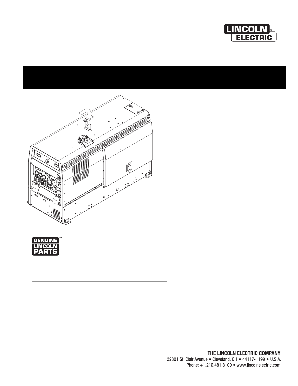
VANTAGE 400
For use with machines having Code Numbers:
11530, 11785, 11920, 12305,
12319
Register your machine:
www.lincolnelectric.com/register
Authorized Service and Distributor Locator:
www.lincolnelectric.com/locator
Save for future reference
Date Purchased
Code: (ex: 10859)
Serial: (ex: U1060512345)
IM989-D | Issue D ate Jul-16
© Lincoln Global, Inc. All Rights Reserved.
Need Help? Call 1.888.935.3877
to talk to a Service Representative
Hours of Operation:
8:00 AM to 6:00 PM (ET) Mon. thru Fri.
After hours?
Use “Ask the Experts” at lincolnelectric.com
A Lincoln Service Representative will contact you
no later than the following business day.
For Service outside the USA:
Email: globalservice@lincolnelectric.com
Page 2
THANK YOU FOR SELECTING
A QUALITY PRODUCT BY
LINCOLN ELEC TRIC.
PLEASE EXAMINE CARTON AND EQUIPMENT FOR
DAMAGE IMMEDIATELY
When this equipment is shipped, title passes to the purchaser
upon receipt by the carrier. Consequently, claims for material
damaged in shipment must be made by the purchaser against the
transportation company at the time the shipment is received.
SAFETY DEPENDS ON YOU
Lincoln arc welding and cutting equipment is designed and built
with safety in mind. However, your overall safety can be increased
by proper installation ... and thoughtful operation on your part.
DO NOT INSTALL, OPERATE OR REPAIR THIS EQUIPMENT
WITHOUT READING THIS MANUAL AND THE SAFETY
PRECAUTIONS CONTAINED THROUGHOUT. And, most importantly,
think before you act and be careful.
WARNING
This statement appears where the information must be followed
exactly to avoid serious personal injury or loss of life.
CAUTION
This statement appears where the information must be followed
to avoid minor personal injury or damage to this equipment.
KEEP YOUR HEAD OUT OF THE FUMES.
DON’T get too close to the arc.
se corrective lenses if necessary
U
to stay a reasonable distance
away from the arc.
READ and obey the Safety Data
Sheet (SDS) and the warning label
that appears on all containers of
welding materials.
USE ENOUGH VENTILATION or
exhaust at the arc, or both, to
keep the fumes and gases from
your breathing zone and the general area.
IN A LARGE ROOM OR OUTDOORS, natural ventilation may be
adequate if you keep your head out of the fumes (See below).
USE NATURAL DRAFTS or fans to keep the fumes away
from your face.
If you de velop unusual symptoms, see your supervisor.
Perhaps the welding atmosphere and ventilation system
should be checked.
WEAR CORRECT EYE, EAR &
BODY PROTECTION
PROTECT your eyes and face with welding helmet
properly fitted and with proper grade of filter plate
(See ANSI Z49.1).
PROTECT your body from welding spatter and arc
flash with protective clothing including woolen
clothing, flame-proof apron and gloves, leather
leggings, and high boots.
PROTECT others from splatter, flash, and glare
with protective screens or barriers.
IN SOME AREAS, protection from noise may be appropriate.
BE SURE protective equipment is in good condition.
Also, wear safety glasses in work area
AT ALL TIMES.
SPECIAL SITUATIONS
DO NOT WELD OR CUT containers or materials which previously
had been in contact with hazardous substances unless they are
properly cleaned. This is extremely dangerous.
DO NOT WELD OR CUT painted or plated parts unless special
precautions with ventilation have been taken. They can release
highly toxic fumes or gases.
Additional precautionary measures
PROTECT compressed gas cylinders from excessive heat,
mechanical shocks, and arcs; fasten cylinders so they cannot fall.
BE SURE cylinders are never grounded or part of an
electrical circuit.
REMOVE all potential fire hazards from welding area.
ALWAYS HAVE FIRE FIGHTING EQUIPMENT READY FOR
IMMEDIATE USE AND KNOW HOW TO USE IT.
Safety 01 of 04 - 06/15/2016
Page 3
SECTION A:
WARNINGS
CALIFORNIA PROPOSITION 65 WARNINGS
Diesel Engines
Diesel engine exhaust and some of its constituents are known
to the State of California to cause cancer, birth defects, and other
reproductive harm.
Gasoline Engines
The engine exhaust from this product contains chemicals known
to the State of California to cause cancer, birth defects, or other
reproductive harm.
ARC WELDING CAN BE HAZARDOUS. PROTECT
YOURSELF AND OTHERS FROM POSSIBLE SERIOUS
INJURY OR DEATH. KEEP CHILDREN AWAY.
PACEMAKER WEARERS SHOULD CONSULT WITH
THEIR DOCTOR BEFORE OPERATING.
Read and understand the following safety highlights. For
additional safety information, it is strongly recommended
that you purchase a copy of “Safety in Welding & Cutting ANSI Standard Z49.1” from the American Welding Society,
P.O. Box 351040, Miami, Florida 33135 or CSA Standard
W117.2-1974. A Free copy of “Arc Welding Safety” booklet
E205 is available from the Lincoln Electric Company,
22801 St. Clair Avenue, Cleveland, Ohio 44117-1199.
BE SURE THAT ALL INSTALLATION, OPERATION,
MAINTENANCE AND REPAIR PROCEDURES ARE
PERFORMED ONLY BY QUALIFIED INDIVIDUALS.
SAFETY
1.d. Keep all equipment safety guards, covers
and devices in position and in good repair.
Keep hands, hair, clothing and tools away
from V-belts, gears, fans and all other
moving parts when starting, operating or
repairing equipment.
1.e. In some cases it may be necessary to remove safety guards to
perform required maintenance. Remove guards only when
necessary and replace them when the maintenance requiring
heir removal is complete. Always use the greatest care when
t
working near moving parts.
1.f. Do not put your hands near the engine fan. Do not attempt to
override the governor or idler by pushing on the throttle control
rods while the engine is running.
1.g. To prevent accidentally starting gasoline engines while turning
the engine or welding generator during maintenance work,
disconnect the spark plug wires, distributor cap or magneto wire
as appropriate.
1.h. To avoid scalding, do not remove the radiator
pressure cap when the engine is
hot.
ELECTRIC AND
MAGNETIC FIELDS MAY
BE DANGEROUS
2.a. Electric current flowing through any conductor
causes localized Electric and Magnetic Fields (EMF).
Welding current creates EMF fields around welding cables
and welding machines
FOR ENGINE POWERED
EQUIPMENT.
1.a. Turn the engine off before troubleshooting
and maintenance work unless the
maintenance work requires it to be running.
1.b. Operate engines in open, well-ventilated
areas or vent the engine exhaust fumes outdoors.
1.c. Do not add the fuel near an open flame
welding arc or when the engine is running.
Stop the engine and allow it to cool before
refueling to prevent spilled fuel from
vaporizing on contact with hot engine parts
and igniting. Do not spill fuel when filling
tank. If fuel is spilled, wipe it up and do not start engine until
fumes have been eliminated.
2.b. EMF fields may interfere with some pacemakers, and
welders having a pacemaker should consult their physician
before welding.
2.c. Exposure to EMF fields in welding may have other health effects
which are now not known.
2.d. All welders should use the following procedures in order to
minimize exposure to EMF fields from the welding circuit:
2.d.1. Route the electrode and work cables together - Secure
them with tape when possible.
2.d.2. Never coil the electrode lead around your body.
2.d.3. Do not place your body between the electrode and work
cables. If the electrode cable is on your right side, the
work cable should also be on your right side.
2.d.4. Connect the work cable to the workpiece as close as possible to the area being welded.
2.d.5. Do not work next to welding power source.
Safety 02 of 04 - 06/15/2016
Page 4
SAFETY
ELECTRIC SHOCK
CAN KILL.
3.a. The electrode and work (or ground) circuits are
electrically “hot” when the welder is on. Do
not touch these “hot” parts with your bare skin or wet clothing.
Wear dry, hole-free gloves to insulate hands.
3.b. Insulate yourself from work and ground using dry insulation.
Make certain the insulation is large enough to cover your full area
f physical contact with work and ground.
o
In addition to the normal safety precautions, if
welding must be performed under electrically
hazardous conditions (in damp locations or while
wearing wet clothing; on metal structures such as
floors, gratings or scaffolds; when in cramped
positions such as sitting, kneeling or lying, if there
is a high risk of unavoidable or accidental contact
with the workpiece or ground) use the following
equipment:
• Semiautomatic DC Constant Voltage (Wire) Welder.
• DC Manual (Stick) Welder.
• AC Welder with Reduced Voltage Control.
3.c. In semiautomatic or automatic wire welding, the electrode,
electrode reel, welding head, nozzle or semiautomatic welding
gun are also electrically “hot”.
3.d. Always be sure the work cable makes a good electrical
connection with the metal being welded. The connection should
be as close as possible to the area being welded.
3.e. Ground the work or metal to be welded to a good electrical (earth)
ground.
3.f. Maintain the electrode holder, work clamp, welding cable and
welding machine in good, safe operating condition. Replace
damaged insulation.
3.g. Never dip the electrode in water for cooling.
3.h. Never simultaneously touch electrically “hot” parts of electrode
holders connected to two welders because voltage
two can be the total of the open circuit voltage of both
welders.
3.i. When working above floor level, use a safety belt to protect
yourself from a fall should you get a shock.
between the
ARC RAYS CAN BURN.
4.a. Use a shield with the proper filter and cover plates to protect your
eyes from sparks and the rays of the arc when welding or
observing open arc welding. Headshield and filter lens should
conform to ANSI Z87. I standards.
4.b. Use suitable clothing made from durable flame-resistant material
to protect your skin and that of your helpers from the arc rays.
4.c. Protect other nearby personnel with suitable, non-flammable
screening and/or warn them not to watch the arc nor expose
themselves to the arc rays or to hot spatter or metal.
FUMES AND GASES
CAN BE DANGEROUS.
5.a. Welding may produce fumes and gases
hazardous to health. Avoid breathing these fumes and gases.
When welding, keep your head out of the fume. Use enough
ventilation and/or exhaust at the arc to keep fumes and gases
away from the breathing zone. When welding hardfacing
(see instructions on container or SDS) or on lead
or cadmium plated steel and other metals or
coatings which produce highly toxic fumes, keep
exposure as low as possible and within applicable
OSHA PEL and ACGIH TLV limits using local
exhaust or mechanical ventilation unless exposure
assessments indicate otherwise. In confined
spaces or in some circumstances, outdoors, a
respirator may also be required. Additional
precautions are also required when welding
on galvanized steel.
5. b. The operation of welding fume control equipment is affected by
various factors including proper use and positioning of the
equipment, maintenance of the equipment and the specific
welding procedure and application involved. Worker exposure
level should be checked upon installation and periodically
thereafter to be certain it is within applicable OSHA PEL and
ACGIH TLV limits.
5.c. Do not weld in locations near chlorinated hydrocarbon vapors
coming from degreasing, cleaning or spraying operations. The
heat and rays of the arc can react with solvent vapors to form
phosgene, a highly toxic gas, and other irritating products.
3.j. Also see It ems 6.c. and 8.
5.d. Shielding gases used for arc welding can displace air and
cause
injury or death. Always use enough ventilation, especially in
confined areas, to insure breathing air is safe.
5.e. Read and understand the manufacturer’s instructions for this
equipment and the consumables to be used, including the
Safety Data Sheet (SDS) and follow your employer’s safety
practices. SDS forms are available from your welding
distributor or from the manufacturer.
5.f. Also see item 1.b.
Safety 03 of 04 - 06/15/2016
Page 5
SAFETY
WELDING AND CUTTING
SPARKS CAN CAUSE
FIRE OR EXPLOSION.
6.a. Remove fire hazards from the welding area. If
this is not possible, cover them to prevent the welding sparks
rom starting a fire. Remember that welding sparks and hot
f
materials from welding can easily go through small cracks and
openings to adjacent areas. Avoid welding near hydraulic lines.
Have a fire extinguisher readily available.
6.b. Where compressed gases are to be used at the job site, special
precautions should be used to prevent hazardous situations.
Refer to “Safety in Welding and Cutting” (ANSI Standard Z49.1)
and the operating information for the equipment being used.
6.c. When not welding, make certain no part of the electrode circuit is
touching the work or ground. Accidental contact can cause
overheating and create a fire hazard.
6.d. Do not heat, cut or weld tanks, drums or containers until the
proper steps have been taken to insure that such procedures
will not cause flammable or toxic vapors from substances inside.
They can cause an explosion even though they have been
“cleaned”. For information, purchase “Recommended Safe
Practices for the Preparation for Welding and Cutting of
Containers and Piping That Have Held Hazardous Substances”,
AWS F4.1 from the American Welding Society
(see address above).
6.e. Vent hollow castings or containers before heating, cutting or
welding. They may explode.
6.f. Sparks and spatter are thrown from the welding arc. Wear oil free
protective garments such as leather gloves, heavy shirt, cuffless
trousers, high shoes and a cap over your hair. Wear ear plugs
when welding out of position or in confined places. Always wear
safety glasses with side shields when in a welding area.
6.g. Connect the work cable to the work as close to the welding area
as practical. Work cables connected to the building framework or
other locations away from the welding area increase the
possibility of the welding current passing through lifting chains,
crane cables or other alternate circuits. This can create fire
hazards or overheat lifting chains or cables until they fail.
6.h. Also see item 1.c.
CYLINDER MAY EXPLODE IF
DAMAGED.
7.a. Use only compressed gas cylinders containing
the correct shielding gas for the process used
and properly operating regulators designed for
the gas and pressure used. All hoses, fittings,
tc. should be suitable for the application and
e
maintained in good condition.
7.b. Always keep cylinders in an upright position securely chained to
an undercarriage or fixed support.
7.c. Cylinders should be located:
• Away from areas where they may be struck or subjected
to physical damage.
• A safe distance from arc welding or cutting operations
and any other source of heat, sparks, or flame.
7.d. Never allow the electrode, electrode holder or any other
electrically “hot” parts to touch a cylinder.
7.e. Keep your head and face away from the cylinder valve outlet
when opening the cylinder valve.
7.f. Valve protection caps should always be in place and hand tight
except when the cylinder is in use or connected for use.
7.g. Read and follow the instructions on compressed gas cylinders,
associated equipment, and CGA publication P-l, “Precautions for
Safe Handling of Compressed Gases in Cylinders,” available from
the Compressed Gas Association, 14501 George Carter Way
Chantilly, VA 20151.
FOR ELECTRICALLY
POWERED EQUIPMENT.
8.a. Turn off input power using the disconnect
switch at the fuse box before working on
the equipment.
8.b. Install equipment in accordance with the U.S. National Electrical
Code, all local codes and the manufacturer’s recommendations.
6.I. Read and follow NFPA 51B “Standard for Fire Prevention During
Welding, Cutting and Other Hot Work”, available from NFPA, 1
Batterymarch Park, PO box 9101, Quincy, MA 022690-9101.
6.j. Do not use a welding power source for pipe thawing.
8.c. Ground the equipment in accordance with the U.S. National
Electrical Code and the manufacturer’s recommendations.
Refer to
http://www.lincolnelectric.com/safety
for additional safety information.
Safety 04 of 04 - 06/15/2016
Page 6

VANTAGE 400
TABLE OF CONTENTS
Page
Installation ................................................................................................................................................Section A
Technical Specifications................................................................................................................................A-1
Safety Precautions...................................................................................................................................A-2
VRD (Voltage Reduction Device) ............................................................................................................A-2
Location and Ventilation........................................................................................................................A-2
Stacking ...............................................................................................................................................A-2
Angle of Operation ................................................................................................................................A-2
Lifting......................................................................................................................................................A-2
High Altitude Operation.........................................................................................................................A-3
High Temperature Operation.................................................................................................................A-3
Cold Weather Operation...........................................................................................................................A-3
Towing .................................................................................................................................................A-3
Vehicle Mounting ..................................................................................................................................A-3
Pre-Operation Engine Service........................................................................................................................A-3
Oil ........................................................................................................................................................A-4
Fuel......................................................................................................................................................A-4
Engine Coolant .....................................................................................................................................A-4
Battery Connections..............................................................................................................................A-4
Muffler Outlet Pipe................................................................................................................................A-4
Spark Arrester ......................................................................................................................................A-4
Remote Control........................................................................................................................................A-4
Electrical Connections...................................................................................................................................A-5
Machine Grounding...............................................................................................................................A-5
Welding Terminals................................................................................................................................A-5
Welding Output Cables ............................................................................................................................A-5
Cable Installation .....................................................................................................................................A-5
Auxiliary Power Receptacles and Plugs .........................................................................................................A-6
Standby Power Connections..........................................................................................................................A-6
Premises Wiring .............................................................................................................................................A-7
Connection of Lincoln Electric Wire Feeders .............................................................................................A-8,A-9
________________________________________________________________________________
Operation Section B
Safety Precautions .......................................................................................................................................B-1
General Description.......................................................................................................................................B-1
For Auxiliary Power .......................................................................................................................................B-1
Engine Operation............................................................................................................................................B-1
Add Fuel .......................................................................................................................................................B-1
Break in Period .............................................................................................................................................B-1
Welder Controls......................................................................................................................................B-2,B-3
Engine Controls.............................................................................................................................................B-4
Starting and Stopping the Engine..........................................................................................................B-4
Fuel Consumption.................................................................................................................................B-4
Welding Operation ........................................................................................................................................B-5
Duty Cycle and Electrode Information ...................................................................................................B-5
Constant Current (Stick) Welding ..........................................................................................................B-5
Typical Current Ranges for Tungsten Electrodes ...................................................................................B-5
Downhill Pipe (Stick) Welding ...............................................................................................................B-6
Tig Welding ..........................................................................................................................................B-6
Wire Welding-CV...................................................................................................................................B-7
Arc Gouging..........................................................................................................................................B-7
Auxiliary Power .............................................................................................................................................B-7
Simultaneous Welding and Power Loads...............................................................................................B-7
Extension Cord Recommendations........................................................................................................B-7
________________________________________________________________________________
Accessories .............................................................................................................................Section C
Field Installed
________________________________________________________________________________
Options / Accessories .........................................................................................................C-1
2
Page 7

ANTAGE 400
V
TABLE OF CONTENTS
aintenance ..............................................................................................................................Section D
M
Safety Precautions.......................................................................................................................D-1
Routine Maintenance ....................................................................................................................D-1
Engine Service Items ...................................................................................................................D-1
Engine Oil Change................................................................................................................D-2
Engine Oil Filter Change .......................................................................................................D-2
Air Cleaner ...........................................................................................................................D-2
Service Instructions And Installation Tips for Engine Air Filter ...............................................D-3
Cooling System............................................................................................................................D-4
Fan Belt ...............................................................................................................................D-4
Fuel .....................................................................................................................................D-4
Bleeding the Fuel System.....................................................................................................D-4
Fuel Filter.............................................................................................................................D-5
Engine Adjustment..................................................................................................................D-5
Battery Maintenance...............................................................................................................D-5
Servicing Optional Spark Arrestor ..........................................................................................D-5
Welder / Generator Maintenance................................................................................................D-6
Storage ................................................................................................................................D-6
Cleaning...............................................................................................................................D-6
Brush Removal and Replacement.........................................................................................D-6
GFCI Testing and Resetting Procedure..................................................................................D-6
________________________________________________________________________
Troubleshooting.......................................................................................................................Section E
How to Use Troubleshooting Guide...............................................................................................E-1
Troubleshooting Guide....................................................................................................E-2 thru E-6
________________________________________________________________________
Connection Diagrams, Wiring Diagrams and Dimension Print..............................................Section F
________________________________________________________________________
Parts List .......................................................................................................................................P-590
________________________________________________________________________
3
Page 8

GENERAL DESCRIPTION
The VANTAGE 400 is a diesel engine powered DC multi-process
elding power source and 120 / 240 volt AC power generator.
w
The engine drives a generator that supplies three phase power
for the DC welding circuit, single phase and Three Phase power
for the AC auxiliary outlets. The DC welding control system uses
state of the art Chopper Technology (CT™) for superior welding
performance.
The Vantage 400 is fitted with a selectable VRD (Voltage Reduction
Device). The VRD operates in the CC-Stick mode reducing the OCV
to <13 volts, increasing operator safety when welding is performed in environments with increased hazard of electric shock.
FOR AUXILIARY POWER:
Start the engine and set the IDLER control switch to the desired
operating mode. Full power is available regardless of the welding
control settings providing no welding current is being drawn.
ENGINE OPERATION
Before Starting the Engine:
PRODUCT DESCRIPTION
• Be sure the machine is on a level surface.
• Open side engine door and remove the engine oil dipstick and
wipe it with a clean cloth. Reinsert the dipstick and check the
level on the dipstick.
• Add oil (if necessary) to bring the level up to the full mark. Do
not overfill. Close engine door.
• Check radiator for proper coolant level. (Fill if necessary).
• See Engine Owner’s Manual for specific oil and coolant recommendations.
4
Page 9
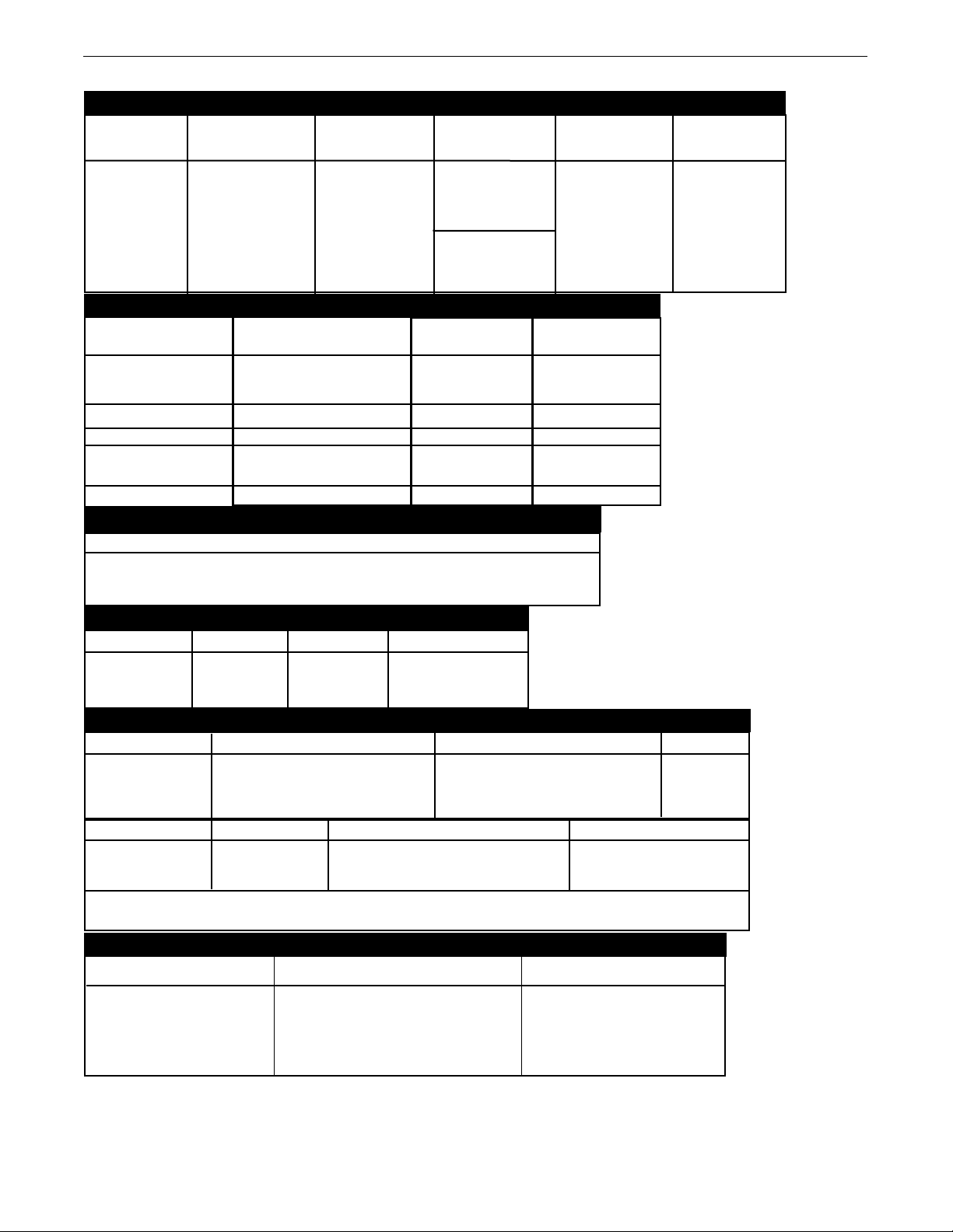
TECHNICAL SPECIFICATIONS - VANTAGE 400 (K2410-3, K2410-4, K2410-7)
INPUT - DIESEL ENGINE
ake/Model Description Speed (RPM) Displacement Starting Capacities
M
PERKINS cu. in. (ltrs.) System
4 cylinder 135.6(2.2)
32.7 HP High Idle 1880 starter (75.7 L)
1800 RPM Bore x Stroke inch (mm) (Group 34; 650 Oil: 8.45Qts. (8L)
404D-22 naturally aspirated Full Load 1800 cold crank amps)
water cooled
Diesel Engine Low Idle 1400 (87.1 x 92.5mm) W/Built in Regulator 8.0 Qts. (7.6L)
3.43 X 3.64
65 Amp Alternator Radiator Coolant:
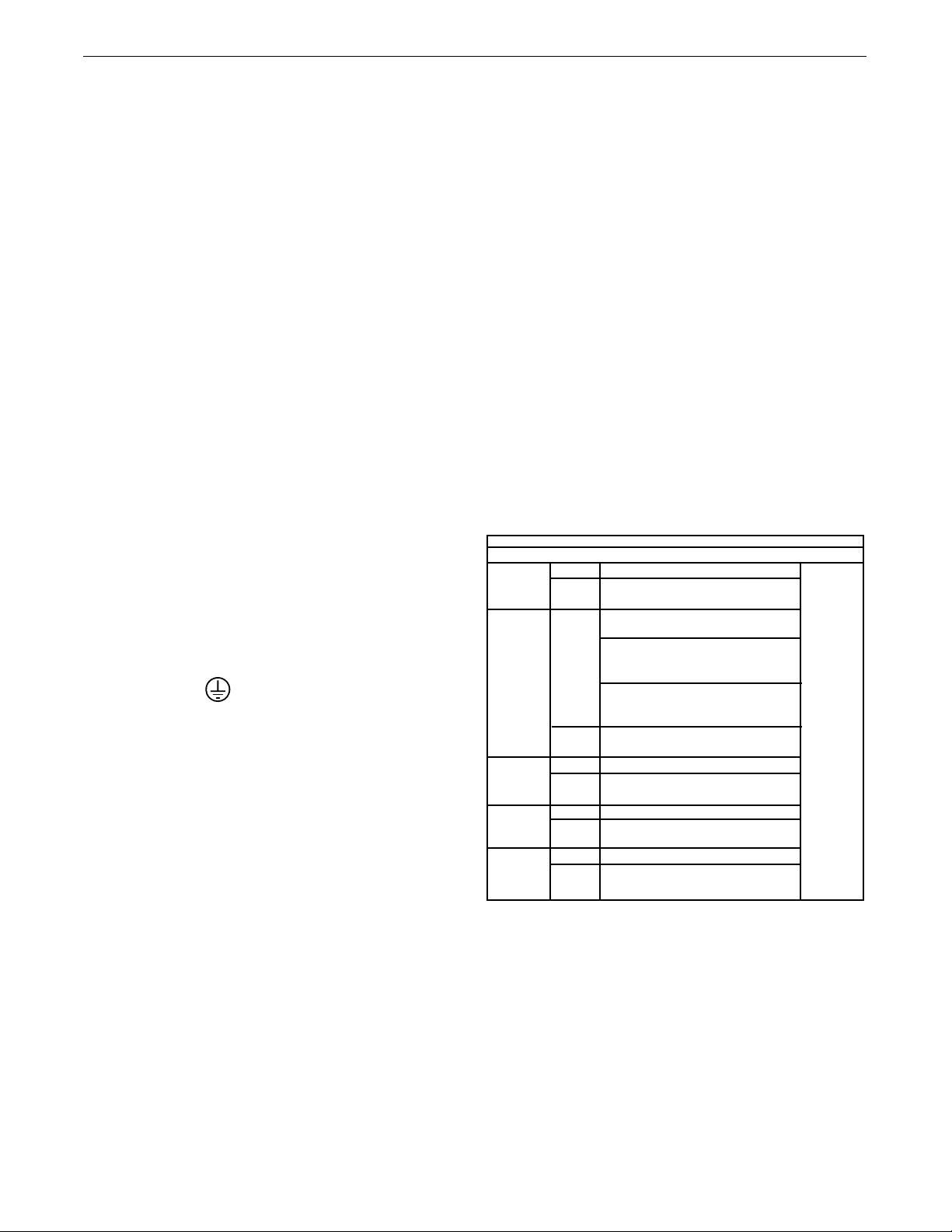
RATED OUTPUT @ 104° F (40° C) - WELDER
Welding Process
DC Constant Current
DC Pipe Current
Touch-Start™TIG
DC Constant Voltage
Arc Gouging
Welding Output
Current/Voltage/Duty Cycle
400A / 36V / 100%
450A / 32V / 100%
300A / 32V / 100%
250A / 30V / 100%
400A / 36V / 100%
450A / 32V / 100%
400A / 36V / 100%
Output Range
30 TO 500 AMPS
40 TO 300 AMPS
20 TO 250 AMPS
14 TO 36 VOLTS
90 to 450 Amps
RATED OUTPUT @ 104° F (40° C).- GENERATOR
Auxiliary Power
12,000 Watts Peak, / 11,000 Watts Continuous, 60 Hz 120/240 Volts Single Phase
19,000 Watts Peak, / 17,000 Watts Continuous, 60 Hz, 240 Volts 3-Phase
1
12VDC Battery &
Max. Weld OCV
@Rated Load RPM
2
60 Volts
Fuel: 20 gal.
INSTALLATIONVANTAGE 400
PHYSICAL DIMENSIONS
HEIGHT WIDTH DEPTH WEIGHT
35.94* in. 25.30 in 60.00 in.
913 mm 643 mm 1524 mm
1230 lbs. (559kg.)
ENGINE
LUBRICATION EMISSIONS FUEL SYSTEM GOVERNOR
Full Pressure K2410-3 EPA Tier 4 Interim Compliant Mechanical Fuel Pump, Auto air bleed Mechanical
with Full Flow Filter K2410-4 EPA Tier 4 Interim Compliant system, Electric shutoff solenoid,
K2410-7 EPA Tier 4 Final Compliant Indirect fuel injector.
AIR CLEANER ENGINE IDLER MUFFLER ENGINE PROTECTION
Low noise Muffler: Shutdown on low oil
Single Element Automatic Idler Top outlet can be rotated. pressure & high engine
Made from long life, aluminized steel. coolant temperature
ENGINE WARRANTY: 2 years / 2000 hours, all non-electric components, 3 years major non-electric components .
See Perkins warranty for details.
MACHINE SPECIFICATIONS
RECEPTACLES AUXILIARY POWER CIRCUIT BREAKER OTHER CIRCUIT BREAKERS
(2) 120VAC Duplex (5-20R) GFCI protected
(1) 120/240VAC Dual Voltage (1) 50AMP for Dual Voltage and for 10AMP for 42V Wire Feeder Power
(Full KVA (14-50R)14-50R) 3-Phase (3-pole)
(1) 240VAC 3-Phase (15-50R)
1. Output rating in watts is equivalent to volt-amperes at unity power factor. Output voltage is within ± 10% at all loads up to rated capacity. When
welding, available auxiliary power will be reduced.
* To Top of enclosure, add 10.68”(271.3mm) to top of exhaust pipe. Add 6.67”(169.4mm) to top of Lift Bail.
2. Reduced to less than 30V in the CC-stick Mode when VRD (VOLTAGE REDUCTION DEVICE) is on.
Two 20AMP for Two Duplex Receptacle 10AMP for Battery Charging Circuit
A-1
Page 10
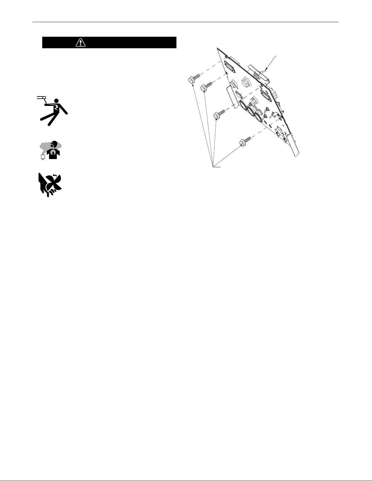
SAFETY PRECAUTIONS
(
VRD)-VOLTAGE REDUCTION DEVICE
S
WITCH IS LOCATED IN THIS AREA.
REMOVE 4 FRONT PANEL
S
CREWS TO ACC ESS
(VRD) SWITCH
WARNING
o not attempt to use this equipment until you have thor-
D
oughly read the engine manufacturer’s manual supplied
with your welder. It includes important safety precautions,
detailed engine starting, operating and maintenance instructions, and parts lists.
-------------------------------------------------------------------
-
ELECTRIC SHOCK can kill.
• Do not touch electrically live parts or electrode with skin or wet clothing.
• Insulate yourself from work and ground
• Always wear dry insulating gloves.
--------------------------------------------------------------------
ENGINE EXHAUST can kill.
• Use in open, well ventilated areas or vent
exhaust outside.
--------------------------------------------------------------------
MOVING PARTS can injure.
• Do not operate with doors open or guards
off.
• Stop engine before servicing.
• Keep away from moving parts.
--------------------------------------------------------------------
See additional warning information at front of this
operator’s manual.
Only qualified personnel should install,
use, or service this equipment.
VRD (VOLTAGE REDUCTION DEVICE)
The VRD feature provides additional safety in the CC-Stick mode especially
in an environment with a higher risk of electric shock such as wet areas and
hot humid sweaty conditions.
The VRD reduces the OCV (Open Circuit Voltage) at the welding output terminals while not welding to less than 30V DC when the resistance of the
output circuit is above 200 (ohms).
The VRD requires that the welding cable connections be kept in good electrical condition because poor connections will contribute to poor starting.
Having good electrical connections also limits the possibility of other safety
issues such as heat-generated damage, burns and fires.
The machine is shipped with the VRD switch in the “Off” position. To turn it
“On” or “Off”.
• Turn the engine “Off”.
• Disconnect the negative battery cable.
• Lower the control panel by removing 4 front panel screws. (See Figure
A.1)
• Place the VRD switch in the “On” or “Off” position. (See Figure A.1)
With the VRD switch in the “On” position, the VRD lights
are enabled.
INSTALLATIONVANTAGE 400
IGURE A.1
F
LOCATION AND VENTILATION
The welder should be located to provide an unrestricted flow of
clean, cool air to the cooling air inlets and to avoid restricting the
cooling air outlets. Also, locate the welder so that the engine
exhaust fumes are properly vented to an outside area.
STACKING
VANTAGE 400 machines cannot be stacked.
ANGLE OF OPERATION
Engines are designed to run in the level condition which is where
the optimum performance is achieved. The maximum angle of
continuous operation is 25 degrees in all directions, 35 degrees
Intermittent (less than 10 minutes continuous) in all directions. If
the engine is to be operated at an angle, provisions must be
made for checking and maintaining the oil level at the normal
(FULL) oil capacity in the crankcase.
When operating the welder at an angle, the effective fuel capacity will be slightly less than the amount specified.
LIFTING
The VANTAGE 400 weighs approximately 1345lbs. (611kg.) with
a full tank of fuel 1230lbs.(559kg) less fuel. A lift bail is mounted
to the machine and should always be used when lifting the
machine.
A-2
Page 11

WARNING
• Lift only with equipment of adequate lifting capacity.
• Be sure machine is stable when lifting.
• Do not lift this machine using lift bail if it
is equipped with a heavy accessory such
as trailer or gas cylinder.
FALLING • Do not lift machine if lift bail is
EQUIPMENT can damaged.
cause injury. • Do not operate machine while
suspended from lift bail.
----------------------------------------------------------------------------
INSTALLATIONVANTAGE 400
. Proper placement of the equipment on the trailer to insure stability side to
3
side and front to back when being moved and when standing by itself
while being operated or serviced.
4. Typical conditions of use, i.e., travel speed; roughness of surface on
which the trailer will be operated; environmental conditions; like mainte-
ance.
n
5. Conformance with federal, state and local laws.
1) Consult applicable federal, state and local laws regarding specific requirements for use on public highways.
(
(1)
NOTE: This machine is furnished with a wet charged battery; if unused
for several months, the battery may require a booster charge. Be careful
to charge the battery with the correct polarity. (See Battery in
“Maintenance Section”)
HIGH ALTITUDE OPERATION
At higher altitudes, output derating may be necessary. For maximum rating,
derate the machine 2.5% to 3.5% for every 1000 ft. (305m). Due to new
EPA and other local emissions regulations, modifications to the engine for
high altitude are restricted within the United States. For use above 6000
ft.(1828 m) an authorized Perkins engine field service shop should be contacted to determine if any adjustments can be made for operation in higher
elevations.
HIGH TEMPERATURE OPERATION
At temperatures above 104°F(40°C), Welder output derating is necessary.
For maximum output ratings, derate the welder output 2 volts for every
18°F
(10°
C) above 104°F(40°C).
Cold weather starting:
With a fully charged battery and the proper oil, the engine should start
satisfactorily down to -15°F(-26C°). If the engine must be frequently
started at or below 0°F (-18°C), it may be desirable to install cold-starting aides. The use of No. 1D diesel fuel is recommended in place of No.
2D at temperatures below 23°F (-5°C). Allow the engine to warm up
before applying a load or switching to high idle.
Note: Extreme cold weather starting may require longer glow
plug operation.
VEHICLE MOUNTING
WARNING
Improperly mounted concentrated loads may cause unstable
vehicle handling and tires or other components to fail.
• Only transport this Equipment on serviceable vehicles
which are rated and designed for such loads.
• Distribute, balance and secure loads so vehicle is stable
under conditions of use.
• Do not exceed maximum rated loads for components
such as suspension, axles and tires.
• Mount equipment base to metal bed or frame of vehicle.
• Follow vehicle manufacturer’s instructions.
----------------------------------------------------------------------------
PRE-OPERATION ENGINE SERVICE
READ the engine operating and maintenance instructions supplied with this machine.
WARNING
WARNING
Under no conditions should ether or other starting fluids be
used with this engine!
----------------------------------------------------------------------------
TOWING
Use a recommended trailer for use with this equipment for road, in-plant
and yard towing by a vehicle(1). If the user adapts a non-Lincoln trailer, he
must assume responsibility that the method of attachment and usage does
not result in a safety hazard or damage the welding equipment. Some of the
factors to be considered are as follows:
1. Design capacity of trailer vs. weight of Lincoln equipment and likely additional attachments.
2. Proper support of, and attachment to, the base of the welding equipment
so there will be no undue stress to the framework.
• Stop engine and allow to cool before fueling
• Do not smoke when fueling.
• Fill fuel tank at a moderate rate and do not overfill.
• Wipe up spilled fuel and allow fumes to clear before
starting engine.
• Keep sparks and flame away from tank.
----------------------------------------------------------------------------
A-3
Page 12
INSTALLATIONVANTAGE 400
OIL
The VANTAGE 400 is shipped with the engine crankcase filled
with high quality SAE 10W-30 Oil that meets classification CG-4
or CH-4 for diesel engines. Check the oil level before starting
he engine. If it is not up to the full mark on the dip stick, add oil
t
as required. Check the oil level every four hours of running time
uring the first 50 running hours. Refer to the engine Operator’s
d
Manual for specific oil recommendations and break-in information. The oil change interval is dependent on the quality of the oil
and the operating environment. Refer to the Engine Operator’s
Manual for more details on the proper service and maintenance
intervals.
FUEL
USE DIESEL FUEL ONLY
WARNING
• Fill the fuel tank with clean, fresh fuel. The capacity of the
tank is 20 gals. (75.7 ltrs). When the fuel gauge reads
empty the tank contains approximately 2 gals. (7.6ltrs.) of
reserve fuel.
WARNING
NOTE: A fuel shut off valve is located on the pre-filter/sedi-
ment filter. Which should be in the closed position
when the welder is not used for extended periods of
time.
----------------------------------------------------------------------------
ENGINE COOLING SYSTEM
MUFFLER OUTLET PIPE
Using the clamp provided secure the outlet pipe to the outlet tube with
the pipe positioned such that it will direct the exhaust in the desired
direction. Tighten using a 9/16" socket or wrench.
SPARK ARRESTER
Some federal, state or local laws may require that gasoline or diesel
engines be equipped with exhaust spark arresters when they are operated in certain locations where unarrested sparks may present a fire
hazard. The standard muffler included with this welder does not qualify
as a spark arrester. When required by local regulations, a suitable spark
arrester, such as the K903-1 must be installed and properly maintained.
WARNING
An incorrect spark arrestor may lead to damage to the engine or
adversely affect performance.
----------------------------------------------------------------------------
REMOTE CONTROL
The VANTAGE® 400 is equipped with a 6-pin and a 14-pin connector.
When in the ARC GOUGING or CV-WIRE modes and when a remote control
is connected to the 6-pin Connector, the auto-sensing circuit automatically
switches the OUTPUT control from control at the welder to remote control.
When in TOUCH START TIG mode and when a Amptrol is connected to the 6Pin Connector, the OUTPUT dial is used to set the maximum current range of
the CURRENT CONTROL of the Amptrol.
When in the CC-STICK or DOWNHILL PIPE mode and when a remote control
is connected to the 6-Pin or 14-Pin connector, the output control is used to
set the maximum current range of the remote.
WARNING
Air to cool the engine is drawn in the side and exhausted
through radiator & case back. It is important that the intake
and exhaust air is not restricted. Allow a minimum clearance of 1ft. (0.6m) from the case back and 16in.(406mm)
from either side of the base to a vertical surface.
----------------------------------------------------------------------------
BATTERY CONNECTION
CAUTION
Use caution as the electrolyte is a strong acid that can burn
skin and damage eyes.
----------------------------------------------------------------------------
The VANTAGE 400 is shipped with the negative battery cable disconnected. Make certain that the RUN-STOP switch is in the
STOP position. Remove the two screws from the battery tray
using a screwdriver or a 3/8" socket. Attach the negative battery
cable to the negative battery terminal and tighten using a 1/2"
socket or wrench.
EXAMPLE: When the OUTPUT CONTROL on the welder is set to 200 amps
the current range on the remote control will be Min.-200 amps, rather than
the full Min.-Max. amps. Any current range that is less than the full range
provides finer current resolution for more fine tuning of the output.
In the CV-WIRE mode, if the feeder being used has a voltage control when
the wire feeder control cable is connected to the 14-Pin Connector, the
auto-sensing circuit automatically makes OUTPUT CONTROL inactive and
the wire feeder voltage control active. Otherwise, the OUTPUT CONTROL is
used to preset the voltage.
The 14-pin connector is used to directly connect a wire feeder control cable.
In the CV-WIRE mode, when the control cable is connected to the 14-pin
connector, the auto-sensing circuit automatically makes the Output Control
inactive and the wire feeder voltage control active.
NOTE: When a wire feeder with a built in welding voltage control is
connected to the 14-pin connector, do not connect anything to the 6pin connector.
----------------------------------------------------------------------------
ELECTRICAL CONNECTIONS
A-4
Page 13
MACHINE GROUNDING
Because this portable engine driven welder creates
its own power, it is not necessary to connect its
frame to an earth ground, unless the machine is connected to
premises wiring (home, shop, etc.)
INSTALLATIONVANTAGE 400
current and duty cycle. Length refers to the distance from the
elder to the work and back to the welder. Cable diameters are
w
increased for long cable lengths to reduce voltage drops.
TABLE A.1
CABLE INSTALLATION
To prevent dangerous electric shock, other equipment to which
this engine driven welder supplies power must:
• Be grounded to the frame of the welder using a grounded
type plug or be double insulated.
WARNING
• Do not ground the machine to a pipe that carries explosive or combustible material.
----------------------------------------------------------------------------
When this welder is mounted on a truck or trailer, its frame
WARNING
must be electrically bonded to the metal frame of the vehicle. Use a #8 or larger copper wire connected between the
machine grounding stud and the frame of the vehicle. When
this engine driven welder is connected to premises wiring
such as that in a home or shop, its frame must be connected
to the system earth ground. See further connection instructions in the section entitled "Standby Power Connections"
as well as the article on grounding in the latest National
Electrical Code and the local code.
In general, if the machine is to be grounded, it should be connected with a #8 or larger copper wire to a solid earth ground
such as a metal water pipe going into the ground for at least ten
feet and having no insulated joints, or to the metal framework of
a building which has been effectively grounded.
The National Electrical Code lists a number of alternate means of
grounding electrical equipment. A machine grounding stud
marked with the symbol is provided on the front of the
welder.
TOTAL COMBINED LENGTH OF
ELECTRODE AND WORK CABLES
Cable Length
0-100 Ft. (0-30 meters)
100-150 Ft. (30-46 meters)
150-200 Ft. (46-61 meters)
Install the welding cables to your VANTAGE 400 as follows.
1. The engine must be OFF to install welding cables.
2. Remove the flanged nuts from the output terminals
3. Connect the electrode holder and work cables to the weld output terminals. The terminals are identified on the case front.
4. Tighten the flanged nuts securely.
5. Be certain that the metal piece you are welding (the “work”) is
properly connected to the work clamp and cable.
6. Check and tighten the connections periodically.
• Loose connections will cause the output terminals to over-
heat. The terminals may eventually melt.
Cable Size for
400 Amps
60% Duty Cycle
2 / 0 AWG
2 / 0 AWG
3 / 0 AWG
CAUTION
• Do not cross the welding cables at the output terminal
connection. Keep the cables isolated and separate from
one another.
----------------------------------------------------------------------------
AUXILIARY POWER RECEPTACLES
WELDING TERMINALS
The VANTAGE 400 is equipped with a toggle switch for selecting
"hot" welding terminal when in the "WELD TERMINALS ON"
position or "cold" welding terminal when in the "REMOTELY
CONTROLLED" position.
WELDING OUTPUT CABLES
With the engine off connect the electrode and work cables to the
output studs. The welding process dictates the polarity of the
electrode cable. These connections should be checked periodically and tightened with a 3/4" wrench.
Table A.1 lists recommended cable sizes and lengths for rated
Start the engine and set the “IDLER” control switch to the “High
Idle” mode. Voltage is now correct at the receptacles for auxiliary
power. This must be done before a tripped GFCI can be reset
properly. See the MAINTENANCE section for more detailed information on testing and resetting the GFCI.
The auxiliary power of the VANTAGE 400 consists of two 20
Amp-120 VAC (5-20R) duplex receptacles with GFCI protection,
one 50 Amp 120/240 VAC (14-50R) receptacle and one 50 Amp
240VAC Three-Phase (15-50R) receptacle.
The auxiliary power capacity is 12,000 watts Peak, 11,000 Watts
Continuous of 60 Hz, single phase power. The auxiliary power
capacity rating in watts is equivalent to volt-amperes at unity
power factor. The max permissible current of the 240 VAC output
A-5
Page 14

INSTALLATIONVANTAGE 400
is 50amps.
The 240 VAC output can be split to provide two separate 120 VAC
utputs with a max permissible current of 50 Amps per output to
o
two separate 120 VAC branch circuits (these circuits cannot be
paralleled). Output voltage is within ± 10% at all loads up to rated
capacity.
The Three-Phases auxiliary power capacity is 17,000 watts peak,
19,000 watts continuous. The maximum current is 45 amps.
120 V DUPLEX RECEPTACLES AND GFCI
A GFCI protects, the two 120V Auxiliary Power receptacles. A
GFCI (Ground Fault Circuit Interrupter) electrical receptacle is a
device to protect against electric shock should a piece of defective equipment connected to it develop a ground fault. If this situation should occur, the GFCI will trip, removing voltage from the
output of the receptacle. If a GFCI is tripped see the MAINTENANCE section for detailed information on testing and resetting it.
A GFCI should be properly tested at least once every month.
The 120 V auxiliary power receptacles should only be used with
three wire grounded type plugs or approved double insulated
tools with two wire plugs. The current rating of any plug used
with the system must be at least equal to the current capacity of
the associated receptacle.
circuit breaker. Maximum rated load for each leg of the 240
AC auxiliary is 50 amperes. Loading above the rated output
V
will reduce output voltage below the allowable - 10% of rated
oltage which may damage appliances or other motor-driven
v
equipment and may result in overheating of the engine
and/or alternator windings.
Install a 50 amp, 120/240 VAC plug (NEMA Type 14-50P) to
•
the double-pole circuit breaker using No. 6, 4 conductor
cable of the desired length. (The 50 amp, 120/240 VAC plug
is available in the optional K802R plug kit or as part number
T12153-9.)
• Plug this cable into the 50 Amp, 120/240 Volt receptacle on
the case front.
NOTE: The 240 V receptacle has two 120 V circuits,
but are of opposite polarities and cannot be paralleled.
All auxiliary power is protected by circuit breakers.
The 120V has 20 Amp circuit breakers for each duplex receptacle. The 120/240V Single Phase and the 240V Three-Phases have
a 50 Amp 3-pole Circuit Breaker that disconnects both hot leads
and all Three Phases simultaneously.
STANDBY POWER CONNECTIONS
The VANTAGE 400 is suitable for temporary, standby or emergency power using the engine manufacturer’s recommended
maintenance schedule.
The VANTAGE 400 can be permanently installed as a standby
power unit for 240 VAC, 3 wire, single phase, 50 amp service.
Connections must be made by a licensed electrician who can
determine how the 120/240 VAC power can be adapted to the
particular installation and comply with all applicable electrical
codes.
• Install the double-pole, double-throw switch between the
power company meter and the premises disconnect. Switch
rating must be the same or greater than the customer’s
premises disconnect and service over current protection.
• Take necessary steps to assure load is limited to the capacity
of the generator by installing a 50 amp, 240 VAC double pole
A-6
Page 15
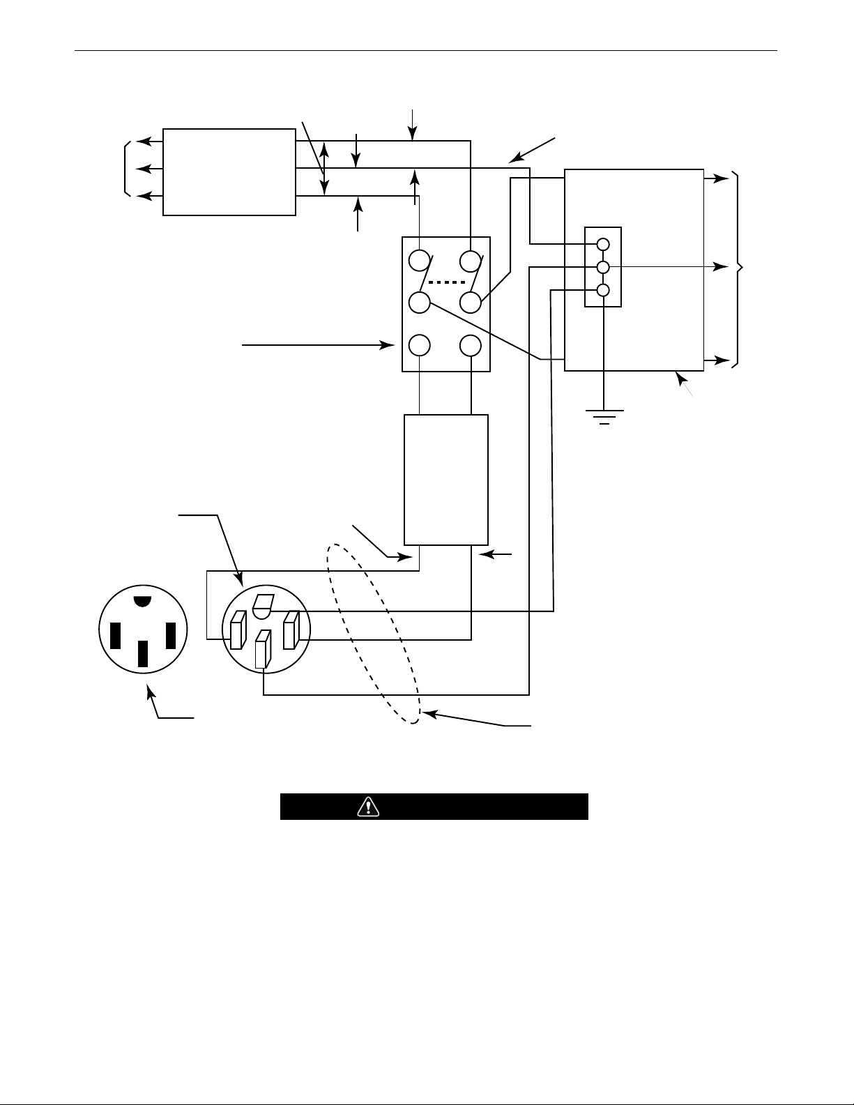
CONNECTION OF VANTAGE 400 TO PREMISES WIRING
240 Volt
6
0 Hz.
3
-Wire
Service
POWER
COMPANY
METER
240 VOLT
120 VOLT
120 VOLT
L
OAD
N
NEUTRAL
BUS
G
ROUND
PREMISES
D
ISCONNECT AND
SERVICE
OVERCURRENT
P
ROTECTION
GND
N
NOTE: No. 6 COPPER CONDUCTOR CABLE SEE
NATIONAL ELECTRICAL CODE FOR ALTERNATE WIRE
SIZE RECOMMENDATIONS.
240 VOLT
G
ROUNDED CONDUCTOR
5
0AMP
240 VOLT
D
OUBLE
POLE
CIRCUIT
BREAKER
D
OUBLE POLE DOUBLE THROW
SWITCH RATING TO BE THE SAME
AS OR GREATER THAN PREMISES
S
ERVICE OVERCURRENT
P
ROTECTION.
50 AMP, 120/240
VOLT PLUG
NEMA TYPE 14-50
50 AMP, 120/240 VOLT
RECEPTACLE
INSTALLATIONVANTAGE 400
WARNING
• Only a licensed, certified, trained electrician should install the machine to a premises or residential electrical system. Be
certain that:
• The installation complies with the National Electrical Code and all other applicable electrical codes.
• The premises is isolated and no feedback into the utility system can occur. Certain state and local laws require the premis-
es to be isolated before the generator is linked to the premises. Check your state and local requirements.
• A double pole, double throw transfer switch in conjunction with the properly rated double throw circuit breaker is connect-
ed between the generator power and the utility meter.
A-7
Page 16

INSTALLATIONVANTAGE 400
CONNECTION OF LINCOLN ELECTRIC WIRE
FEEDERS
Connection of LN-7 or LN-8 to the VANTAGE 400
1. Shut the welder off.
2. Connect the LN-7 or LN-8 per instructions on the appropriate
connection diagram in Section F.
3. Set the "WIRE FEEDER VOLTMETER" switch to either "+" or
"-" as required by the electrode being used.
4. Set the "MODE" switch to the "CV WIRE " position.
5. Set the "ARC CONTROL" knob to "0" initially and adjust to
suit.
6. Set the "WELD TERMINALS" switch to the "REMOTELY CON-
TROLLED" position.
7. Set the "IDLE" switch to the "HIGH" position.
Connection of LN-15 to the VANTAGE 400
4. Control Cable Model:
• Connect Control Cable between Engine Welder and Feeder.
• Set the "WELD TERMINALS" switch to "REMOTELY
CONTROLLED"
Set the MODE switch to the "CV-WIRE " position.
•
• Set the "WIRE FEEDER VOLTMETER" switch to either "+" or
"-" as required by the electrode polarity being used.
• Set the "ARC CONTROL" knob to "0" initially and adjust to
suit.
• Set the "IDLE" switch to the "AUTO" position.
• When the gun trigger is closed, the current sensing circuit
will cause the VANTAGE 400 engine to go to the high idle
speed, the wire will begin to feed and the welding process
started. When welding is stopped, the engine will revert to
low idle speed after approximately 12 seconds unless
welding is resumed.
1. Shut the welder off.
2. For electrode Positive, connect the electrode cable to the "+"
terminal of the welder and work cable to the "-" terminal of
the welder. For electrode Negative, connect the electrode
cable to the "-" terminal of the welder and work cable to the
"+" terminal of the welder.
3. Across The-Arc Model:
• Attach the single lead from the front of the LN-15 to work
using the spring clip at the end of the lead. This is a control
lead to supply current to the wire feeder motor; it does not
carry welding current.
• Set the "WELD TERMINALS" switch to "WELD TERMINALS
ON".
• When the gun trigger is closed, the current sensing circuit
will cause the VANTAGE 400 engine to go to the high idle
speed, the wire will begin to feed and the welding process
started. When welding is stopped, the engine will revert to
low idle speed after approximately 12 seconds unless
welding is resumed.
A-8
Page 17

INSTALLATIONVANTAGE 400
WARNING
Connection of the LN-25 to the VANTAGE 400
Shut off welder before makin g any elec tri cal
connections.
----------------------------------------------------------------------------
The LN-25 with or without an internal contactor may be used
with the VANTAGE 400. See the appropriate connection diagram
in Section F.
NOTE: The LN-25 (K431) Remote Control Module and (K432)
Remote Cable are not recommended for use with the VANTAGE
400.
1. Shut the welder off.
2. For electrode Positive, connect the electrode cable from the
LN-25 to the "+" terminal of the welder and work cable to
the "-" terminal of the welder. For electrode Negative, connect the electrode cable from the LN-25 to the "-" terminal
of the welder and work cable to the "+" terminal of the
welder.
Spool Gun (K487-25) and Cobramatic to
VANTAGE 400
• Shut the welder off.
• Connect per instructions on the appropriate connection diagram in Section F.
Connection of PRINCE XL SPOOL GUN to the VANTAGE 400
Connection of the Prince XL Spool Gun requires the use of the
K1849-1 Adapter Module.
• Shut the Welder off.
• For electrode Positive, connect the electrode cable to the "+"
terminal of the welder and work cable to the "-" terminal of
the welder. For electrode Negative, connect the electrode
cable "-" terminal of the welder and work cable to the "+"
terminal of the welder.
• Connect the Control Cable of the Spool Gun to the Adapter
Module and connect the Control Cable of the Adapter Module
to the Welder.
3. Attach the single lead from the front of the LN-25 to work
using the spring clip at the end of the lead. This is a control
lead to supply current to the wire feeder motor; it does not
carry welding current.
4. Set the MODE switch to the "CV-WIRE " position.
5. Set the "WELD TERMINALS" switch to "WELD TERMINALS
ON"
6. Set the "ARC CONTROL" knob to "0" initially and adjust to
suit.
7. Set the "IDLE" switch to the "AUTO" position. When not
welding, the VANTAGE 400 engine will be at the low idle
speed. If you are using an LN-25 with an internal contactor,
the electrode is not energized until the gun trigger is closed.
8. When the gun trigger is closed, the current sensing circuit
will cause the VANTAGE 400 engine to go to the high idle
speed, the wire will begin to feed and the welding process
started. When welding is stopped, the engine will revert to
low idle speed after approximately 12 seconds unless welding is resumed.
• Connect the Gas Hose.
• Set the MODE switch to the "CV-WIRE " position.
• Set the "WELD TERMINALS" switch to "WELD TERMINALS
ON".
• Set the "ARC CONTROL" knob to "0" initially and adjust to
suit.
• Set the “IDLE” switch to the “HIGH” position.
CAUTION
If you are using an LN-25 without an internal contactor, the
electrode will be energized when the VANTAGE 400 is started.
----------------------------------------------------------------------------
A-9
Page 18
SAFETY PRECAUTIONS
WARNING
Do not attempt to use this equipment until you have thoroughly read the engine manufacturer’s manual supplied
with your welder. It includes important safety precautions,
et ailed engine starting, operating an d maintenanc e
d
instructions, and parts lists.
--------------------------------------------------------------------
ELECTRIC SHOCK can kill.
• Do not touch electrically live parts or electrode with skin
or wet clothing.
• Insulate yourself from work and ground
• Always wear dry insulating gloves.
• Always operate the welder with the hinged
door closed and the side panels in place.
• Read carefully the Safety Precautions page before operat-
ing this machine. Always follow these and any other safety procedures included in this manual and in the Engine
Instruction Manual.
GENERAL DESCRIPTION
The VANTAGE 400 is a diesel engine powered DC multi-process
welding power source and 120 / 240 volt AC power generator.
The engine drives a generator that supplies three phase power
for the DC welding circuit, single phase and Three Phase power
for the AC auxiliary outlets. The DC welding control system uses
state of the art Chopper Technology (CT™) for superior welding
performance.
Th e Van ta ge 400 is fitt ed with a sele ct ab le VRD(Voltage
Reduction Device). The VRD operates in the CC-Stick mode
reducing the OCV to <13 volts, increasing operator safety when
welding is performed in environments with increased hazard of
electric shock.
OPERATIONVANTAGE 400
ADD FUEL
WARNING
• Stop engine while fueling.
• Do not smoke when fueling.
• Keep sparks and flame away from
tank.
• Do not leave unattended while fueling.
• Wipe up spilled fuel and allow fumes
to clear before starting engine.
DIESEL FUEL
can cause fire.
• Do not overfill tank, fuel expansion
may cause overflow.
DIESEL FUEL ONLY
---------------------------------------------------------------------------
• Remove the fuel tank cap.
• Fill the tank. DO NOT FILL THE TANK TO THE POINT OF OVERFLOW.
• Replace the fuel cap and tighten securely.
• See Engine Owner’s Manual for specific fuel recommendations.
BREAK-IN PERIOD
The engine will use a small amount of oil during its “break-in”
period. The break-in period is about 50 running hours.
FOR AUXILIARY POWER:
Start the engine and set the IDLER control switch to the desired
operating mode. Full power is available regardless of the welding
control settings providing no welding current is being drawn.
ENGINE OPERATION
Before Starting the Engine:
• Be sure the machine is on a level surface.
• Open side engine door and remove the engine oil dipstick and
wipe it with a clean cloth. Reinsert the dipstick and check the
level on the dipstick.
• Add oil (if necessary) to bring the level up to the full mark. Do
not overfill. Close engine door.
• Check radiator for proper coolant level. (Fill if necessary).
• See Engine Owner’s Manual for specific oil and coolant
recommendations.
Check the oil every four hours during break-in. Change the oil
after the first 50 hours of operation and every 200 hours thereafter. Change the oil filter at each oil change.
CAUTION
During break-in, subject the Welder to moderate loads.
Avoid long periods running at idle. Before stopping the
engine, remove all loads and allow the engine to cool several minutes.
---------------------------------------------------------------------------
B-1
Page 19
ANTAGE 400
V
13
OPERATION
FIGURE B.1
1
11
2
9
3
10
4
14
12
17
22
16
20
5
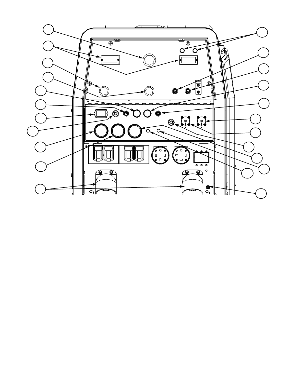
WELDING CONTROLS (Figure B.1)
1. OUTPUT CONTROL-
voltage or current as displayed on the digital meters for the five welding modes. When in the ARC GOUGING or CV-WIRE modes and when
a remote control is connected to the 6-Pin or 14-Pin Connector, the
auto-sensing circuit automatically switches the OUTPUT CONTROL
from control at the welder to the remote control.
The OUTPUT dial is used to preset the output
15
8
7
23
21
18
19
6
2. DIGITAL OUTPUT METERS-The digital meters allow the output
voltage (CV-WIRE mode) or current (CC-STICK,DOWN HILL PIPE and
TIG modes) to be set prior to welding using the OUTPUT control dial.
During welding, the meter display the actual output voltage (VOLTS)
and current (AMPS). A memory feature holds the display of both
meters on for seven seconds after welding is stopped. This allows
the operator to read the actual current and voltage just prior to when
welding was ceased.
When in the CC-STICK or DOWNHILL PIPE mode and when a remote
control is connected to the 6-Pin or 14-Pin connector, the output control is used to set the maximum current range of the remote.
EXAMPLE: When the OUTPUT CONTROL on the welder is set to 200
amps the current range on the remote control will be Min.-200 amps,
rather than the full Min.-Max. amps. Any current range that is less
than the full range provides finer current resolution for more fine tuning of the output.
In the CV-WIRE mode, if the feeder being used has a voltage control
when the wire feeder control cable is connected to the 14-Pin
Connector, the auto-sensing circuit automatically makes OUTPUT
CONTROL inactive and the wire feeder voltag e control active.
Otherwise, the OUTPUT CONTROL is used to preset the voltage.
When in the TOUCH START TIG mode and when an Amptrol is connected to the 6-Pin Connector, the OUTPUT dial is used to set the
maximum current range of the CURRENT CONTROL of the Amptrol.
While the display is being held the left-most decimal point in each
display will be flashing. The accuracy of the meters is +/- 3%.
3. WELD MODE SELECTOR SWITCH-
(Provides Five selectable welding modes)
CV-WIRE
ARC GOUGING
DOWNHILL PIPE
CC-STICK
TOUCH START TIG
B-2
Page 20
ANTAGE 400
V
OPERATION
4. ARC CONTROL- The ARC CONTROL dial is active in the CV-WIRE,
CC-STICK and DOWNHILL PIPE modes, and has different functions in
hese modes. This control is not active in the TIG mode and ARC
t
GOUGING mode.
CC-STICK mode: In this mode, the ARC CONTROL dial sets the short
ircuit current (arc-force) during stick welding to adjust for a soft or
c
crisp arc. Increasing the dial from –10 (soft) to +10 (crisp) increases
the short circuit current and prevents sticking of the electrode to the
plate while welding. This can also increase spatter. It is recommended
that the ARC CONTROL be set to the minimum number without electrode sticking. Start with a setting at 0.
DOWNHILL PIPE mode: In this mode, the ARC CONTROL dial sets the
short circuit current (arc-force) during stick welding to adjust for a soft
or a more forceful digging arc (crisp). Increasing the number from –10
(soft) to +10 (crisp) increases the short circuit current which results in a
more forceful digging arc. Typically a forceful digging arc is preferred for
root and hot passes. A softer arc is preferred for fill and cap passes
where weld puddle control and deposition ("stacking" of iron) are key to
fast travel speeds. It is recommended that the ARC CONTROL be set initially at 0.
CV-WIRE mode: In this mode, turning the ARC CONTROL clock wise
from –10 (soft) to +10 (crisp) changes the arc from soft and washed-in
to crisp and narrow. It acts as an inductance/pinch control. The proper
setting depends on the procedure and operator preference. Start with a
setting of 0.
5. WELD OUTPUT TERMINALS WITH FLANGE NUT- Provides a
connection point for the electrode and work cables.
6. GROUND STUD- Provides a connection point for connecting
the machine case to earth ground.
7. 14-PIN CONNECTOR- For attaching wire feeder control cables.
Includes contactor closure circuit, auto-sensing remote control circuit,
and 120V and 42V power. The remote control circuit operates the same
as the 6 Pin Amphenol.
8. 6-PIN CONNECTOR- For attaching optional remote control equip-
ment. Includes auto-sensing remote control circuit.
9. WELD TERMINALS CONTROL SWITCH- In the WELD TERMI-
NALS ON position, the output is electrically hot all the time. In the
REMOTELY CONTROLLED position, the output is controlled by a wire
feeder or amptrol device, and is electrically off until a remote switch is
depressed.
cator lights. A red light when lit indicates
reater than 30V and a green light when
Voltage) is equal to or
lit indicates
OCV(Open Circuit Voltage)
g
OCV (Open Circuit
is less than 30V.
The VRD “On/Off” switch inside the control panel must be “On”
for the VRD function to be active and the lights to be enabled.
When the machine is first started with VRD enabled, both lights
ill illuminate for 5 seconds.
w
These lights monitor the
OCV (Open Circuit Voltage)
and weld
voltage at all times. In the CC-Stick mode when not welding the
green light will illuminate indicating that the VRD has reduced
the OCV to less than 30V. During welding the red light will illuminate whenever the arc voltage is equal to or greater than 30V.
This means that the red and green light may alternate depending on the weld voltage. This is normal operation.
If the red light remains illuminated when not welding in the CCstick mode, the VRD is not functioning properly. Please refer to
your local field service shop for service.
If the VRD is turned “On” and the lights don’t come “On”, refer to
the trouble shooting section.
TABLE B.1
MODE VRD "ON" VRD "OFF"
CC-STICK OCV Green (OCV Reduced)
While Red or Green
Welding (Depends on Weld Voltage) *
CV-WIRE OCV Red (OCV Not Reduced)
Weld Terminals On
Red (OCV Not Reduced)
Weld Terminals Remotely Controlled
Gun Trigger Closed
Green (No OCV)
Weld Terminals Remotely Controlled
Gun Trigger Open No Lights
While Red or Green
Welding (Depends on Weld Voltage) *
PIPE OCV Green (No Output)
While Not Applicable (No Output)
Welding
ARC GOUGING
While Not Applicable (No Output)
Welding
TIG OCV Green (Process is Low Voltage)
While Green (Process is Low Voltage)
Welding
OCV Green (No Output)
VRD INDICATOR LIGHTS
* It is normal for the lights to alternate between colors while welding.
10. WIRE FEEDER VOLTMETER SWITCH:
Matches the polarity of the wire feeder voltmeter to the polarity
of the electrode.
11. VRD (Voltage Reduction Device) INDICATOR
LIGHTS- On the front panel of the VANTAGE 400 are two indi-
B-3
Page 21
ANTAGE 400
V
OPERATION
ENGINE CONTROLS:
12. RUN/STOP SWITCH - RUN position energizes the engine prior
to starting. STOP position stops the engine. The oil pressure interlock switch prevents battery drain if the switch is left in the RUN
osition and the engine is not operating.
p
13. GLOW PLUG PUSH BUTTON -
• When pushed activates the glow plugs. Glow plug should not be
activated for more than 20 seconds continuously.
14. START PUSH BUTTON - Energizes the starter motor to crank
the engine.
15. IDLER SWITCH- Has two positions as follows:
1) In the HIGH position, the engine runs at the high idle speed
controlled by the engine governor.
2) In the AUTO position, the idler operates as follows:
• When switched from HIGH to AUTO or after starting the engine,
the engine will operate at full speed for approximately 12 seconds
and then go to low idle speed.
• When the electrode touches the work or power is drawn for lights
or tools (approximately 100 Watts minimum), the engine accelerates and operates at full speed.
• When welding ceases or the AC power load is turned off, a fixed
time delay of approximately 12 seconds starts. If the welding or
AC power load is not restarted before the end of the time delay,
the idler reduces the engine speed to low idle speed.
• The engine will automatically return to high idle speed when there
is welding load or AC power load reapplied.
16. ELECTRIC FUEL GAUGE- The electric fuel gauge gives accu-
rate and reliable indication as to how much fuel is in the fuel tank.
17. ENGINE HOUR METER- Displays the total time that the engine has
been running. This meter is useful for scheduling prescribed maintenance.
18. ENGINE PROTECTION LIGHT- A warning indicator light for Low
Oil Pressure and/or Coolant Over Temperature.The light is off when the
systems are functioning properly. The light will come on and the engine
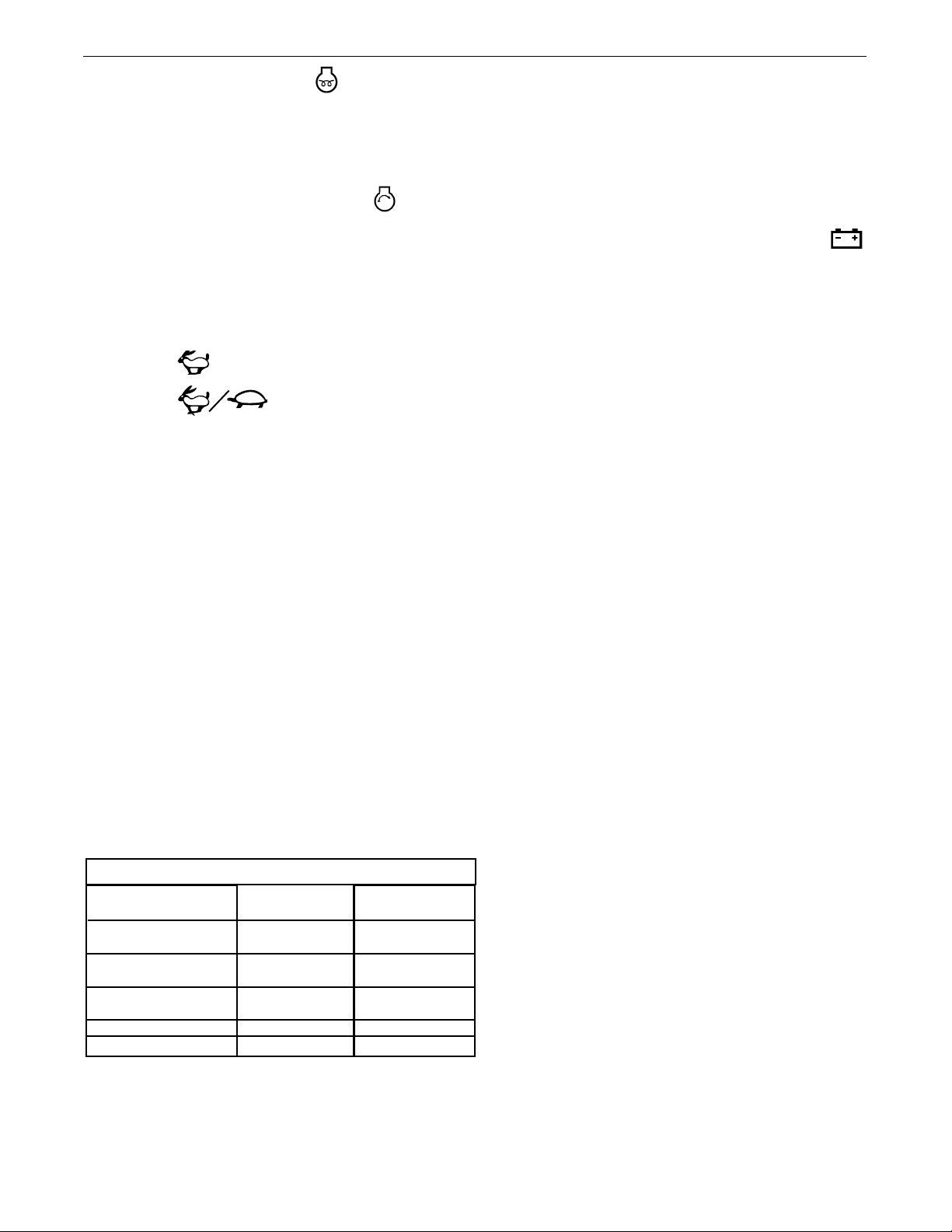
TABLE B.2
TYPICAL VANTAGE 400 FUEL CONSUMPTION
Low Idle - No Load
1400 R.P.M.
High Idle - No Load
1880 R.P.M.
DC Weld Output
400 Amps @ 36 Volts
17,000 Watts 3 Phase
11,000 Watts 1 Phase
PERKINS 404C-22
Gal./Hr (Liters/Hr)
.26 (.97)
.42 (1.57)
1.18 (4.46)
1.24 (4.68)
.90 (3.42)
Running Time for
20 gallons / hours
76.92
47.62
16.95
16.13
22.22
will shutdown when there is Low Oil Pressure and/or the Coolant is Over
Temperature.
Note: The light remains off when the RUN-STOP switch is in the "ON"
position prior to starting the engine.However if the engine is not started
within 60 seconds the light will come on. When this happens the RUNSTOP switch must be returned to the "OFF" position to reset the engine
protection system and light.
19. BATTERY CHARGING LIGHT- A warning indicator light
for Low/No battery charge. The light is off when the systems are functioning properly. The light will come on if there is a Low/No battery con-
dition but the machine will continue to run.
Note: The light may or may not come on when the RUN-STOP switch is in
the "ON" position. It will come on during cranking and stay on until the
engine starts. After starting the engine the light will go off unless a Low/No
battery charge condition exists.
20. COOLANT TEMPERATURE GAUGE-A indicator of engine coolant
temperature.
21. OIL PRESSURE GAUGE- A indicator of engine Oil Pressure.
22. CIRCUIT BREAKER- For protection of Battery Charging Circuit.
23. CIRCUIT BREAKER- For protection of 42V Wire Feeder circuit.
STARTING THE ENGINE
1. Remove all plugs connected to the AC power receptacles.
2. Set IDLER switch to AUTO.
3. Press Glow Plug Button and hold 15 to 20 seconds.
4. Set the RUN/STOP switch to RUN.
5. Press START button until the engine starts or for up to 10 seconds.
Continue to hold the glow plug button for up to an additional 10 seconds.
6. Release the engine START button immediately when the engine
starts.
7. The engine will run at high idle speed for approximately 12 seconds
and then drop to low idle speed. Allow the engine to warm up at low
idle for several minutes before applying a load and/or switching to
high idle. Allow a longer warm up time in cold weather.
NOTE: This data is for reference only. Fuel consumption is
approximate and can be influenced by many factors, including
engine maintenance, environmental conditions and fuel quality.
B-4
Page 22

ANTAGE 400
V
OPERATION
NOTE: If the unit fails to start turn Run/Stop switch to off and
repeat step 3 through step 7 after waiting 30 seconds.
CAUTION
• Do not allow the starter motor to run continuously
than 20 seconds.
• Do not push the START button while the engine is run-
ning because this can damage the ring gear and/or the
starter motor.
• IF the Engine Protection or Battery Charging Lights do
“not” turn off shortly after starting the engine shut off
the engine immediately and determine the cause.
----------------------------------------------------------------------------
NOTE: When starting for the first time, or after and extended
period of time of not operating, it will take longer than normal to
start because the fuel pump has to fill the fuel system. For best
results, bleed the fuel system as indicated in Maintenance
Section of this manual.
STOPPING THE ENGINE
Remove all welding and auxiliary power loads and allow the
engine to run at low idle speed for a few minutes to cool the
engine.
STOP the engine by placing the RUN-STOP switch in the STOP
position.
NOTE: A fuel shut off valve is located on the fuel pre-filter.
WELDER OPERATION
DUTY CYCLE
Duty Cycle is the percentage of time the load is being applied in a 10
minute period. For example a 60% duty cycle, represents 6 minutes
of load and 4 minutes of no load in a 10 minute period.
ELECTRODE INFORMATION
For any electrode the procedures should be kept within the rating of the machine. For information on electrodes and their proper application see (www.lincolnelectric.com) or the appropriate
Lincoln publication.
for more
set to the minimum number without electrode sticking. Start with
the dial set at 0.
NOTE: Due to the low OCV with the VRD on, a very slight
delay during striking of the electrodes may occur. Due to the
equirement of the resistance in the circuit to be low for a
r
VRD to operate, a good metal-to-metal contact must be made
between the metal core of the electrode and the job. A poor
connection anywhere in the welding output circuit may limit
the operation of the VRD. This includes a good connection of
the work clamp to the job. The work clamp should be connected as close as practical to where the welding will be performed.
A. For New Electrodes
E6010 - Touch, Lift to Start the Arc
E7018, E7024 - Touch, Rock Back and Forth in Joint, Lift .
Once the arc is started, normal welding technique for the
application is then used.
B. For Re-Striking Electrodes
Some electrodes form a cone at the end of the electrode after
the welding arc has been broken, particularly iron powder
and low hydrogen electrodes. This cone will need to be broken off in order to have the metal core of the electrode make
contact.
E6010 - Push, Twist in Joint, Lift
E7018, E7024 - Push, Rock Back and Forth in Joint, Lift.
Once the arc is started, normal welding technique for the
application is then used.
For other electrodes the above techniques should be tried
first and varied as needed to suit operator preference. The
goal for successful starting is good metal to metal contact.
For indicator light operation, see table B.1.
DOWNHILL PIPE Welding
The VANTAGE 400 can be used with a broad range of DC stick electrodes. The MODE switch provides two stick welding settings as follows:
CONSTANT CURRENT (CC-STICK) WELDING
The CC-STICK position of the MODE switch is designed for horizontal
and vertical-up welding with all types of electrodes, especially low
hydrogen. The OUTPUT CONTROL dial adjusts the full output range
for stick welding.
The ARC CONTROL dial sets the short circuit current (arc-force) during
stick welding to adjust for a soft or crisp arc. Increasing the number
from -10(soft) to +10(crisp) increases the short circuit current and
prevents sticking of the electrode to the plate while welding. This can
also increase spatter. It is recommended that the ARC CONTROL be
This slope controlled setting is intended for "out-of-position" and
"down hill" pipe welding where the operator would like to control
the current level by changing the arc length.
The OUTPUT CONTROL dial adjusts the full output range for pipe
welding.
The ARC CONTROL dial sets the short circuit current (arc-force)
during stick welding to adjust for a soft or more forceful digging
arc (crisp). Increasing the number from -10(soft) to +10(crisp)
increases the short circuit current which results in a more forceful digging arc.
Typically a forceful digging arc is preferred for root and hot passes. A softer arc is preferred for fill and cap passes where weld
puddle control and deposition (“stacking” of iron) are key to fast
B-5
Page 23

ANTAGE 400
V
travel speeds. This can also increase spatter.
It is recommended that the ARC CONTROL be set to the minimum
umber without electrode sticking. Start with the dial set at 0.
n
NOTE: With the VRD switch in the “ON” position there is no output in
the DOWNHILL PIPE mode.
For indicator light operation, see table
B.1.
TIG WELDING
The TOUCH START TIG setting of the MODE switch is for DC TIG
(Tungsten Inert Gas) welding. To initiate a weld, the OUTPUT CONTROL dial is first set to the desired current and the tungsten is
touched to the work. During the time the tungsten is touching the
work there is very little voltage or current and, in general, no tungsten contamination. Then, the tungsten is gently lifted off the work
in a rocking motion, which establishes the arc.
OPERATION
he VANTAGE 400 can be used in a wide variety of DC TIG weld-
T
ing applications. In general the ‘Touch Start’ feature allows contamination free starting without the use of a Hi-frequency unit. If
desired, the K930-2 TIG Module can be used with the VANTAGE
400. The settings are for reference.
ANTAGE 400 settings when using the K930-2 TIG Module with
V
an Amptrol or Arc Start Switch:
• Set the MODE Switch to the TOUCH START TIG setting.
• Set the "IDLER" Switch to the "AUTO" position.
• Set the "WELDING TERMINALS" switch to the "REMOTELY CONTROLLED" position. This will keep the "Solid State" contactor open
and provide a "cold" electrode until the Amptrol or Arc Start Switch
is pressed.
When in the TOUCH START TIG mode and when a Amptrol is
connected to the 6-Pin connector the OUTPUT CONTROL dial is
used to set the maximum current range of the current control of
the Amptrol.
When using the TIG Module, the OUTPUT CONTROL on the VANTAGE
400 is used to set the maximum range of the CURRENT CONTROL on
the TIG Module or an Amptrol if connected to the TIG Module.
NOTE: The TIG process is to receive a low voltage welding process.
There is no difference in operation with the VRD “On” or “Off” for
The ARC CONTROL is not active in the TIG mode. To STOP a
this mode. For indicator light operation, see table B.1.
weld, simply pull the TIG torch away from the work.
When the arc voltage reaches approximately 30 Volts the arc will
go out and the machine will reset the current to the Touch Start
level.
To reinitiate the arc, retouch the tungsten to the work and lift.
Alternatively, the weld can be stopped by releasing the Amptrol
or arc start switch.
WIRE WELDING-CV
Connect a wire feeder to the VANTAGE 400 according to the instructions
in INSTALLATION INSTRUCTIONS Section.
The VANTAGE 400 in the CV-WIRE mode, permits it to be used with a
broad range of flux cored wire (Innershield and Outershield) electrodes
and solid wires for MIG welding (gas metal arc welding). Welding can be
TABLE B.3
TYPICAL CURRENT RANGES
Tungsten Electrode DCEN (-) DCEP (+) Approximate Argon Gas Flow TIG TORCH
Diameter in. (mm) Flow Rate C.F.H. ( l /min.) Nozzle Size (4), (5)
1%, 2% Thoriated 1%, 2% Thoriated Aluminum Stainless Steel
Tungsten Tungsten
.010 (.25) 2-15 (3) 3-8 (2-4) 3-8 (2-4) #4, #5, #6
0.020 (.50) 5-20 (3) 5-10 (3-5) 5-10 (3-5)
0.040 (1.0) 15-80 (3) 5-10 (3-5) 5-10 (3-5)
1/16 (1.6) 70-150 10-20 5-10 (3-5) 9-13 (4-6) #5, #6
3/32 (2.4) 150-250 15-30 13-17 (6-8) 11-15 (5-7) #6, #7, #8
1/8 (3.2) 250-400 25-40 15-23 (7-11) 11-15 (5-7)
5/32 (4.0) 400-500 40-55 21-25 (10-12) 13-17 (6-8) #8, #10
3/16 (4.8) 500-750 55-80 23-27 (11-13) 18-22 (8-10)
1/4 (6.4) 750-1000 80-125 28-32 (13-15) 23-27 (11-13)
(1) When used with argon gas. The current ranges shown must be reduced when using argon/helium or pure helium shielding gases.
(2) Tungsten electrodes are classified as follows by the American Welding Society (AWS):
Pure EWP
1% Thoriated EWTh-1
2% Thoriated EWTh-2
Though not yet recognized by the AWS, Ceriated Tungsten is now widely accepted as a substitute for 2% Thoriated Tungsten in AC and DC applications.
(3) DCEP is not commonly used in these sizes.
(4) TIG torch nozzle "sizes" are in multiples of 1/16ths of an inch:
(5) TIG torch nozzles are typically made from alumina ceramic. Special applications may require lava nozzles, which are less prone to breakage, but cannot withstand high temperatures and high duty cycles.
# 4 = 1/4 in. (6 mm)
# 5 = 5/16 in. (8 mm)
# 6 = 3/8 in. (10 mm)
# 7 = 7/16 in. (11 mm)
# 8 = _ in. (12.5 mm)
#10 = 5/8 in. (16 mm)
(1)
FOR TUNGSTEN ELECTRODES
(2)
B-6
Page 24
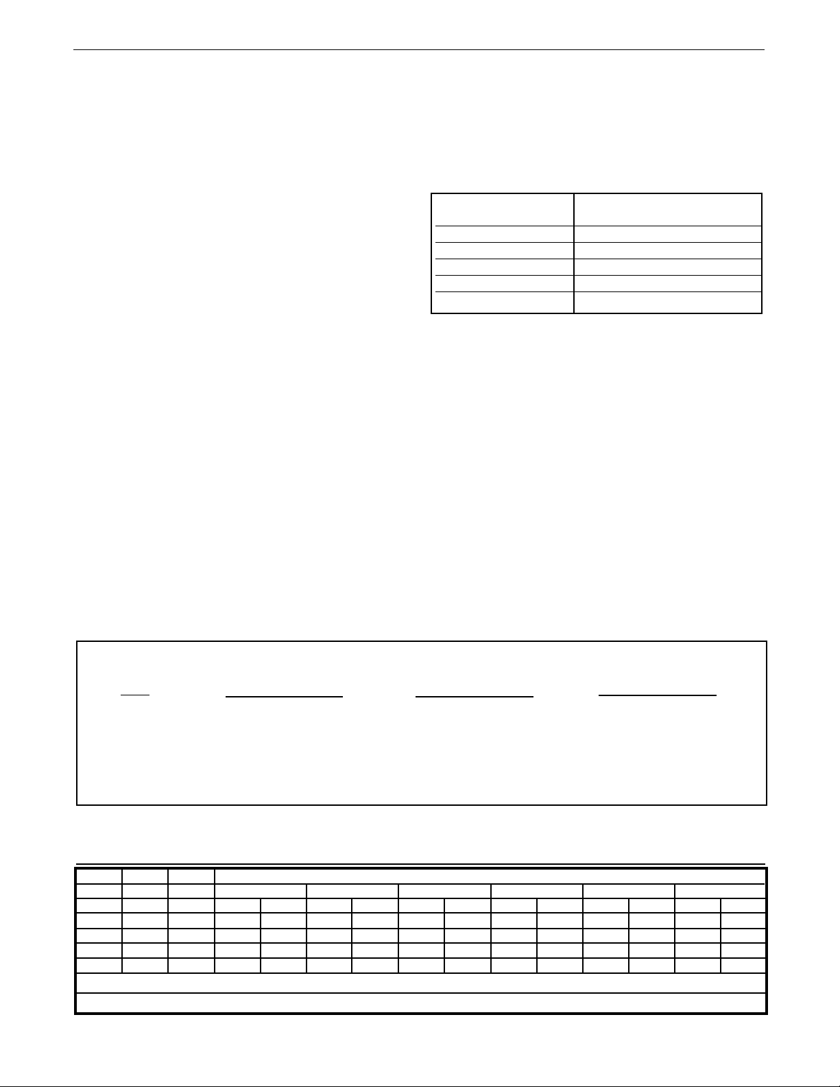
ANTAGE 400
V
OPERATION
finely tuned using the ARC CONTROL. Turning the ARC CONTROL clockwise from –10 (soft) to +10 (crisp) changes the arc from soft and
washed-in to crisp and narrow. It acts as an inductance/pinch control.
The proper setting depends on the procedure and operator preference.
Start with the dial set at 0.
NOTE: In the CV-Mode with VRD “On”, the OCV(Open Circuit Voltage) is
not reduced. For indicator light operation, see table B.1.
ARC GOUGING
The VANTAGE 400 can be used for arc gouging. For optimal performance, set the MODE switch to
et the OUTPUT CONTROL knob to adjust output current to the desired
S
level for the gouging electrode being used according to the ratings in
the following Table B.4.
Carbon Diameter
1/8"(3.2mm) 60-90 Amps
5/32"(4.0mm) 90-150 Amps
3/16"9(4.8mm) 200-250 Amps
1/4"(6.4mm) 300-400 Amps
5/16"(8.0mm) 400-Max.Amps
The ARC CONTROL is not active in the ARC GOUGING Mode. The
ARC CONTROL is automatically set to maximum when the ARC
GOUGING mode is selected which provides the best ARC GOUGING performance.
NOTE: With the VRD switch in the “ON” position there is no output in the Arc Gouging Mode. For indicator light operation, see
Table B.1.
ARC GOUGING.
TABLE B.4
Current Range (DC, electrode
positive)
Weld
Amps
0
100
200
300
400
500
PLUS
AUXILIARY POWER:
Start the engine and set the IDLER control switch to the desired
operating mode. Full power is available regardless of the welding
control settings providing no welding current is being drawn.
Simultaneous Welding and Auxiliary Power Loads
The a uxi liary power r ati ngs are wi th no weld ing l oad .
Simultaneous welding and power loads are specified in the following Table B.5.
TABLE B.5
VANTAGE 400 Simultaneous Welding and Power Loads
1 PHASE
WATTS AMPS
11,000 46
11,000 46
8,000 33
4700 20
1700 7
WATTS AMPS
17,000 41
15,400 37
13,000 31
OR
9400 23
3400 8
00
TABLE B.6
VANTAGE 400 (CE) Extension Cord Length Recommendations
(Use the shortest length extension cord possible sized per the following table.)
3 PHASE
WATTS AMPS
11,000 11,000 -
OR
8,000 4,700 1,700 -
00
BOTH 1 & 3 PHASE
00
Current
(Amps)
15
20
15
20
44
Voltage
Volts
120
120
240
240
240
Load
(Watts)
1800
2400
3600
4800
9500
Maximum Allowable Cord Length in ft. (m) for Conductor Size
14 AWG 12 AWG 10 AWG 8 AWG 6 AWG 4 AWG
30
60
(9)
(18)
40
30
75
60
Conductor size is based on maximum 2.0% voltage drop.
(12)
(9)
(23)
(18)
75
50
150
100
50
B-7
(23)
(15)
(46)
(30)
(15)
125
88
225
175
90
(38)
(27)
(69)
(53)
(27)
175
138
350
275
150
(53)
(42)
(107)
(84)
(46)
300
225
600
450
225
(91)
(69)
(183)
(137)
(69)
Page 25

ANTAGE 400
V
ACCESSORIES
FIELD INSTALLED OPTIONS / ACCESSORIES
2641-2 FOUR WHEELED STEERABLE YARD TRAILER
K
For in plant and yard towing. Comes standard with a Duo-Hitch™, a 2” Ball and
Lunette Eye combination Hitch.
K2636-1 TRAILER - Two-wheeled trailer with optional fender and light package.
For highway use, consult applicable federal, state, and local laws regarding possible additional requirements. Comes standard with a Duo-Hitch™, a 2” Ball and
Lunette Eye combination hitch. Order:
K2636-1 Trailer
K2639-1 Fender & Light Kit
K2640-1 Cable Storage Rack
K903-1 SPARK ARRESTOR - Includes a heavy gage steel, approved spark
arrestor, clamp and adapter for mounting to the muffler exhaust pipe.
K704 ACCESSORY SET - Includes 35 ft. (10m) of electrode cable and 30 ft.
(9.1m) of work cable, head shield, work clamp electrode holder. Cables are
rated at 400 amps, 100% duty cycle.
K857 25 ft (7.6m) or K857-1 100 ft. (30.4m) REMOTE CONTROL
Portable control provides same dial range as the output control on the welder.
Has a convenient 6 pin plug for easy connection to the welder.
K802N POWER PLUG KIT
Provides four 120 volt plugs rated at 20 amps each and one dual voltage, full
KVA plug rated at 120/240 volts, 50 amps.
K802R POWER PLUG KIT
Provides four 120 volt plugs rated at 15 amps each and one dual voltage, full
KVA plug rated at 120/240 volts, 50 amps.
WIRE FEEDER OPTIONS
K449 LN-25 - Includes internal contactor for across the arc operation
no control cable). Provides “cold” electrode until gun trigger is pressed.
(
Includes gas solenoid.
K1870-1 LN-15 Across the Arc Wire Feeder.
ortable, lightweight, compact CC/CV unit for flux-cored and MIG weld-
P
ing. Includes Gas Solenoid, adjustable flow meter and internal contactor.
For 10-15 lb. (4.5-6.8kg) spools.
Magnum Gun and Magnum Gun Connector Kit are required for gasshielded welding. Innershield Gun is required for gasless welding.
K126-2 Magnum 350 Innershield Gun
K1802-1 Magnum 300 MIG Gun (for LN-25)
K470-2 Magnum 300 MIG Gun (for LN-15, Includes Connector Kit)
K466-10 Connector Kit (for LN-15, K470-2)
K1500-1 Gun Receiver Bushing (for LN-15 & K126-2)
K487-25 Magnum SG Spool Gun
Hand held semiautomatic wire feeder. Requires SG Control Module and
Input Cable.
K488 SG Control Module (For Magnum Spool Gun)
The Interface between the power source and the spool gun. Provides
control of the wire speed and gas flow. For use with a K487-25 spool
gun.
K691-10 Input Cable (For SG Control Module)
For Lincoln engine power sources with 14-pin MS-type connection, separate 115V NEMA receptacles and output stud connections.
Note: See Wire Feeder IM manuals for appropriate Drive Roll and Guide
Tubes.
T12153-9 50 AMP, 120/240V POWER PLUG (1-Phase)
T12153-10 50 AMP, 240V POWER PLUG (3-Phase)
K1816-1 FULL KVA ADAPTER KIT
Plugs into the 120/240V NEMA 14-50R receptacle on the case front (which
accepts 4-prong plugs) and converts it to a NEMA 6-50R receptacle, (which
accepts 3-prong plugs.) For connection of Lincoln equipment with NEMA 6-50
Plug.
K1858-1 SERVICE INDICATOR KIT- Provides a GO / NO-GO visual indication of
air cleaner element useful service life. Filter service based on restriction readings
allows the longest life possible from the filter and best engine protection.
K2679-1 COLD WEATHER HEATER AND TARP KIT
For engine starting and operation in extreme cold weather conditions down to 40ºF / -40ºC (with the use of OW40 synthetic oil and arctic diesel fuel), includes
120VAC engine block heater, and radiator grill tarp.
TIG OPTIONS
K1783-9 Pro -Torch® PTA-26V TIG Torch
Air Cooled 200 amp torch (2 piece) equipped with valve for gas flow
control. 25 ft. (7.6m) length.
KP509 Magnum Parts Kit for PTA-26V TIG Torch
Magnum Parts Kit provides all the torch accessories you need to start
welding. Parts kit provides collets, collet bodies, a black cap, alumina
nozzles and tungstens in a variety of sizes, all packaged in an easy to
carry reclosable sack.
K870 Foot Amptrol®
K963-3 Hand Amptrol®
K2347-1 Precision TIG 185 Ready-Pak(For AC TIG)
K2350-1 Invertec® V205-T AC/DC One-Pak™ Package
(For AC TIG)
PLASMA CUTTING
K1580-1 Pro-Cut 55
Cuts metal using the 3-phase AC generator power from the engine driven welder. Accepts 3-phase or 1-phase input power. Requires the
K1816-1 Full KVA adapter
power.
kit, if connected for 1-phase input
C-1
Page 26

ANTAGE 400
MAINTENANCE ITEM
TYPE OR QUANTITY
I
Coolant level
I
Concentration of antifreeze
50/50 Water/Ethylene Glycol
R
Coolant (NOTE 3)
9.5qt., 9.0L
I
Engine oil level (NOTE 1)
R
R
Engine oil (NOTE 1 & 3)
8.45qt., 8L (including filter)
R
R
Engine oil filter
Perkins #140517050
C
Drain water separator & fuel strainer
R
Water separator element
Lincoln #M20840-A
R
Fuel filter canister
Perkins #130366120
I
Tension of alternator drive belt
I
Alternator drive belt wear
R
Alternator drive belt
Perkins #080109107
C
Air filter (earlier check may be req’d)
R
Air filter element
Donaldson #P821575
R
Renew the engine breather
I
Tighten cylinder head
I
Valve clearances
Intake .008”, exhaust .008”
I
Electrical systems
I
All nuts and bolts for tightness
I
Injector performance
Contact Perkins
I
Leaks or engine damage
I
Battery
ENGINE SERVICE (NOTE 2)
E
VERY DAY OR EVERY 8 HOURS
FIRST SERVICE (20 / 50 HOURS)
EVERY 100 HOURS OR 3 MONTHS
EVERY 200 HOURS OR 6 MONTHS
EVERY 500 HOURS OR 12 MONTHS
EVERY 1000 HOURS OR ANNUALLY
I = Inspect C = CleanR = Replace
ENGINE SERVICE
Notes:
(1) Consult Engine Operators Manual for oil recommendations.
(2) Consult Engine Operators Manual for additional
maintenance schedule information.
(3) Fill slowly! Ensure correct quantity is used.
Above operations to be carried out by trained personnel with
reference to the workshop manual where necessary.
These preventative maintenance periods apply to average
conditions of operation. If necessary use shorter periods.
S26354 VM
WARRANTY WORK PERFORMED ON THE ENGINE CONTAINED
IN THIS MACHINE, IF NOT BILLABLE TO THE ENGINE MANUFACTURER,
SHOULD BE PRE-APPROVED BY CALLING
THE LINCOLN ELECTRIC COMPANY AT 888-935-3877
V
SAFETY PRECAUTIONS
WARNING
Have qualif ied personne l do all maintena nce and
•
roubleshooting work.
t
Turn the engine off before working inside the machine or
•
ervicing the engine.
s
• Remove guards only when necessary to perform mainte-
nance and replace them when the maintenance requiring
their removal is complete. If guards are missing from
th e ma chine, obtain repla cemen ts fro m a L incoln
Distributor. (See Operating Manual Parts List.)
MAINTENANCE
ead the Safety Precautions in the front of this manual and
R
in the Engine Owner’s Manual before working on this
machine.
Keep all equipment safety guards, covers, and devices in
position and in good repair. Keep hands, hair, clothing, and
tools away from the gears, fans, and all other moving parts
hen starting, operating, or repairing the equipment.
w
----------------------------------------------------------------------------
Routine Maintenance
At the end of each day’s use, refill the fuel tank to minimize
moisture condensation in the tank. Running out of fuel tends to
draw dirt into the fuel system. Also, check the crankcase oil
level and add oil if indicated.
D-1
Page 27

ANTAGE 400
V
MAINTENANCE
ENGINE OIL CHANGE
Drain the engine oil while the engine is warm to assure rapid and
complete draining. It is recommended that each time the oil is
changed the oil filter be changed as well.
• Be sure the unit is off. Disconnect the negative battery cable to
nsure safety.
e
• Locate oil drain hose and valve in bottom of base and pull
through the hole in the battery access panel on the welder.
• Open oil drain valve by lifting up spring loaded lever and rotate
90
counterclockwise. Pull to open and drain the oil into a suit-
°
able container for disposal.
• Close the drain valve by rotating lever 90° clockwise.
• Re-fill the crankcase to the upper limit mark on the dipstick
with the recommended oil (see engine operation manual OR
engine service items decal OR below). Replace and tighten the
oil filler cap securely.
• Push oil drain hose and valve back into unit, re-connect negative battery cable, and close doors and engine top cover before
restarting unit.Wash your hands with soap and water after handling used motor oil. Please dispose of used motor oil in a
manner that is compatible with the environment. We suggest
you take it in a sealed container to your local service station or
recycling center for reclamation. DO NOT throw it in the trash;
pour it on the ground or down a drain.
should be taken during filter removal to not disrupt or damage
in any way the fuel lines.
• Clean the filter mounting base and coat the gasket of the
new filter with clean engine oil.
• Screw the new filter on by hand until the gasket contacts the
mounting base. Using an oil filter wrench, tighten the filter an
additional 1/2 to 7/8 of a turn.
• Refill the crankcase with the specified amount of the recommended engine oil. Reinstall the oil filler cap and tighten
securely.
• Start the engine and check for oil filter leaks.
• Stop the engine and check the oil level. If necessary, add oil to
the upper limit mark on the dipstick.
WARNING
• Never use gasoline or low flash point solvents for cleaning
the air cleaner element. A fire or explosion could result.
• Never run the engine without the air cleaner. Rapid engine
wear will result from contaminants, such as dust and dirt
being drawn into the engine.
----------------------------------------------------------------------------
AIR CLEANER
CAUTION
Use motor oil designed for diesel engines that meets requirements for API service classification CC/CD/CE/CF/CF-4/CG-4 or
CH-4.
ACEA E1/E2/E3. Always check the API service label on the oil container to be sure it includes the letters indicated. (Note: An Sgrade oil must not be used in a diesel engine or damage may
result. It IS permissible to use an oil that meets S and C grade
service classifications.)
SAE 10W30 is recommended for general, all temperature use, 5F
to 104F (-15C to 40C).
See engine owner’s manual for more specific information on oil
viscosity recommendations.
OIL FILTER CHANGE
• Drain the oil.
• Remove the oil filter with an oil filter wrench and drain the oil
into a suitable container. Discard the used filter. Note: Care
The diesel engine is equipped with a dry type air filter. Never
apply oil to it. Service the air cleaner as follows:
Replace the element every 500 hours of operation. Under dusty
conditions, replace sooner.
D-2
Page 28

ANTAGE 400
Unfasten or unlatch the
s
ervice cover. Because
the filter fits tightly over the
outlet tube to create the critical seal, there will
be some initial resistance, similar to breaking
the seal on a jar. Gently move the end of the filter
back and forth to break the seal then rotate while
pulling straight out. Avoid knocking the filter
against the housing.
Remove the FilterRemove the Filter
Rotate the
lter while
pulling
straight out.
If your air cleaner has a safety filter, replace it every third primary
filter change. Remove the safety filter as you would the primary
filter. Make sure you cover the air cleaner outlet tube to avoid any
unfiltered contaminant dropping into the engine.
If your air cleaner is equipped with a Vacuator Valve
Visually check and physically squeeze to make sure the
valve is flexible and not inverted, damaged or plugged.
Inspect the new filter carefully, paying attention to
the inside of the open end, which is the
sealing area. NEVER install a damaged
f
ilter. A new Donaldson radial seal
filter may have a dry lubricant on the
seal to aid installation.
If you're servicing the safety filter, this should be seated into
position before installing the primary filter.
Insert the new filter carefully. Seat
the filter by hand, making certain it is
completely into the air cleaner housing
before securing the cover in place.
If the service cover hits the filter before it is fully in place, remove
the cover and push the filter (by hand) further into the air cleaner
and try again. The cover should go on with no extra force.
Once the filter is in place, secure the service cover.
Make sure that all mounting bands, clamps, bolts, and connections
in the entire air cleaner system are tight. Check for holes in piping
and repair if needed. Any leaks in your intake piping will send dust
directly to the engine!
The critical sealing area will stretch
slightly, adjust itself and distribute the sealing pressure evenly. To
complete a tight seal, apply pressure by hand at the outer rim of
the filter, not the flexible center. (Avoid pushing on the center of the
urethane end cap.) No cover pressure is required to hold the seal.
NEVER use the service cover to push the filter into place! Using the
cover to push the filter in could cause damage to the housing, cover
fasteners and will void the warranty.
Visually inspect the old filter for any signs
of leaks. A streak of dust on the clean side
of the filter is a telltale sign. Remove any
cause of leaks before installing new filter.
Clean Both Surfaces of the Outlet TubeClean Both Surfaces of the Outlet Tube
and Check the Vacuator™ Valveand Check the Vac uato r™ Valve
Inspect the OldInspect the Old
Filter for Leak CluesFilter for Leak Clues
Inspect the New Filter for DamageInspect the New Filter for Damage
Insert the New Radial Seal Filter ProperlyInsert the New Radial Seal Filter Properly
Check Connectors for Tight FitCheck Connectors for Tight Fit
NEVER use the service cover toNEVER use the service cover to
push the filter into place! Usingpush the filter into place! Using
the cover to push the filter in couldthe cover to push the filter in could
cause damage to the housing, covercause damage to the housing, cover
fasteners and will void the warranty.fasteners and will void the warranty.
CautionCaution
Use a clean cloth to wipe the filter sealing surface and the inside of
the outlet tube. Contaminant on the sealing surface could hinder an
effective seal and cause leakage. Make sure that all contaminant is
removed before the new filter is inserted. Dirt accidently transferred
to the inside of the outlet tube will reach the engine and cause
wear. Engine manufacturers say that it takes only a few grams of
dirt to "dust" an engine! Be careful not to damage the sealing area
on the tube.
Wipe both sides
of the outlet
tube clean.
Outer edge of the
outlet tube
Inner edge of the
outlet tube
Service InstructionsService Instructions
Single- and Two-Stage Engine Air CleanersSingle- and Two-Stage Engine Air Cleaners
V
MAINTENANCE
D-3
Page 29

ANTAGE 400
V
MAINTENANCE
COOLING SYSTEM
WARNING
HOT COOLANT
• Do not remove cap if radiator is hot.
--------------------------------------------------------------------
Check the coolant level by observing the level in the radiator and
recovery bottle. Add 50/50 antifreeze / water solution if the level
is close to or below the "LOW" mark. do not fill above the "FULL"
mark. Remove radiator cap and add coolant to radiator. Fill up to
the top of the tube in the radiator filler neck which includes a
connecting hose coming from the thermostat housing.
To drain the coolant, open the valve at the bottom of the radiator.
Open the radiator cap to allow complete drainage. (Tighten the
valve and refill with a 50/50 antifreeze/water solution.) Use an
automotive grade (low silicate) ethylene glycol antifreeze. The
cooling system capacity is 8.0 quarts (7.6L.). Squeeze upper and
lower radiator hoses while filling to bleed air from system
coolant. Replace and tighten the radiator cap.
can burn skin.
CAUTION
Always premix the antifreeze and clean tap water before
adding to the radiator. It is very important that a precise
50/50 solution be used with this engine year round. This
gives proper cooling during hot weather and freezing protection to -34° F (-37° C).
Cooling solution exceeding 50% ethylene glycol can result in
engine overheating and damage to the engine. Coolant solution must be premixed before adding to radiator.
----------------------------------------------------------------------------
FUEL
At the end of each day’s use, refill the fuel tank to minimize
moisture condensation and dirt contamination in the fuel line.
Do not overfill; leave room for the fuel to expand.
Use only fresh No. 2D diesel fuel, the use of No. 1D diesel fuel is
recommended in place of No. 2D at temperatures below 23°F (5°C). Do not use kerosene.
See the Engine Operator's Manual for instructions on replacing
the fuel filter.
BLEEDING THE FUEL SYSTEM
You may need to bleed air from the fuel system if the fuel filter
or fuel lines have been detached, the fuel tank has been ran
empty or after periods of long storage. It is recommended that
the fuel shutoff valve be closed during periods of non-use.
WARNING
To avoid personal injury, do not bleed a hot engine. This
could cause fuel to spill onto a hot exhaust manifold, creating a danger of fire.
----------------------------------------------------------------------------
Bleed the fuel system as follows:
1. Fill the fuel tank with fuel.
2. Open the fuel shut off valve.
3. Loosen bleed fitting on the fuel injector manifold.
4. Operate hand priming lever until fuel comes out the bleed
screw on the injector manifold. This could take 20-30 seconds of rapid operation of the priming lever. Tighten bleed fitting on injector manifold.
5. Follow normal STARTING procedures until engine starts.
Periodically remove the dirt from the radiator fins.
Periodically check the fan belt and radiator hoses. Replace if
signs of deterioration are found.
TIGHTENING THE FAN BELT
If the fan belt is loose, the engine can overheat and the battery
lose its charge. Check tightness by pressing on the belt midway
between the pulleys. It should deflect about .25 in.(6.4 mm)
under a load of 20 lbs.(9 Kg).
D-4
Page 30

ANTAGE 400
V
MAINTENANCE
FUEL FILTER
. Check the fuel filter and fuel pre-filter for water accumulation
1
or sediment.
2. Replace the fuel filter if it is found with excessive water accumulation or sediment. Empty fuel pre-filter.
ENGINE ADJUSTMENT
OVERSPEED IS HAZARDOUS
The maximum allowable high idle speed for this machine is
1890 RPM, no load. Do NOT tamper with governor components
or setting or make any other adjustments to increase the
maximum speed. Severe personal injury and damage to the
machine can result if operated at speeds above maximum.
Adjustments to the engine are to be made only by a Lincoln
Service Center or an authorized Field Service Shop.
BATTERY MAINTENANCE
To access the battery, remove the battery tray from the front of
the machine with 3/8” nut driver or flat head screw driver. Pull
the tray out of machine far enough to disconnect the negative
and then positive battery cables. The tray can then be tilted and
lifted to remove the entire tray and battery from the machine for
easy service.
WARNING
GASES FROM BATTERY can explode.
ª Keep sparks, flame and cigarettes away from battery.
To prevent EXPLOSION when:
• INSTALLING A NEW BATTERY — discon-
nect negative cable from old battery first
and connect to new battery last.
• CONNECTING A BATTERY CHARGER —
remove battery from welder by disconnecting negative cable first, then positive
cable and battery clamp. When reinstalling, connect
negative cable last. Keep well ventilated.
CLEANING THE BATTERY
eep the battery clean by wiping it with a damp cloth when dirty.
K
If the terminals appear corroded, disconnect the battery cables
and wash the terminals with an ammonia solution or a solution
of 1/4 pound (0.1113 kg) of baking soda and 1 quart (0.9461L)
of water. Be sure the battery vent plugs (if equipped) are tight so
that none of the solution enters the cells.
fter cleaning, flush the outside of the battery, the battery com-
A
partment, and surrounding areas with clear water. Coat the battery terminals lightly with petroleum jelly or a non-conductive
grease to retard corrosion.
Keep the battery clean and dry. Moisture accumulation on the
battery can lead to more rapid discharge and early battery failure.
CHECKING THE ELECTROLYTE LEVEL
If battery cells are low, fill them to the neck of the filler hole with
distilled water and recharge. If one cell is low, check for leaks.
CHARGING THE BATTERY
When you charge, jump, replace, or otherwise connect battery
cables to the battery, be sure the polarity is correct. Improper
polarity can damage the charging circuit. The VANTAGE 400 positive (+) battery terminal has a red terminal cover.
If you need to charge the battery with an external charger, disconnect the negative cable first, then the positive cable before
you attach the charger leads. After the battery is charged,
reconnect the positive battery cable first and the negative cable
last. Failure to do so can result in damage to the internal charger
components.
Follow the instructions of the battery charger manufacturer for
proper charger settings and charging time.
SERVICING OPTIONAL SPARK ARRESTOR
Clean every 100 hours.
WELDER / GENERATOR MAINTENANCE
STORAGE: Store in clean, dry protected areas.
• USING A BOOSTER — connect positive lead to battery
first then connect negative lead to negative battery lead
at engine foot.
BATTERY ACID can burn eyes and skin.
ª Wear gloves and eye protection and be careful when
working near battery.
• Follow instructions printed on battery.
WARNING
• MUFFLER MAY BE HOT
• ALLOW ENGINE TO COOL BEFORE INSTALLING THE SPARK
ARRESTER!
• DO NOT OPERATE ENGINE WHILE INSTALLING THE SPARK
ARRESTER!
D-5
Page 31

ANTAGE 400
V
LEANING: Blow out the generator and controls periodically with
C
low pressure air. Do this at least once a week in particularly dirty
areas.
BRUSH REMOVAL AND REPLACEMENT: It’s normal for the
rushes and slip rings to wear and darken slightly. Inspect the
b
brushes when a generator overhaul is necessary.
CAUTION
• Do not attempt to polish slip rings while the engine is running.
MAINTENANCE
GFCI TESTING AND RESETTING PROCEDURE
The GFCI should be properly tested at least once every month or
henever it is tripped. To properly test and reset the GFCI:
w
• If the GFCI has tripped, first carefully remove any load and
check it for damage.
If the equipment has been shut down, it must be restarted.
•
• The equipment needs to be operating at high idle speed and
any necessary adjustments made on the control panel so that
the equipment is providing at least 80 volts to the receptacle
input terminals.
• The circuit breaker for this receptacle must not be tripped.
Reset if necessary.
• Push the "Reset" button located on the GFCI. This will assure
normal GFCI operation.
• Plug a night-light (with an "ON/OFF" switch) or other product
(such as a lamp) into the Duplex receptacle and turn the product "ON".
• Push the "Test" button located on the GFCI. The night-light or
other product should go "OFF".
• Push the "Reset" button, again. The light or other product
should go "ON" again.
WARNING
• Service and Repair should only be performed by Lincoln
Electric Factory Trained Personnel. Unauthorized repairs
performed on this equipment may result in danger to the
technician and machine operator and will invalidate your
factory warranty. For your safety and to avoid Electrical
Shock, please observe all safety notes and precautions.
If the light or other product remains "ON" when the "Test" button is pushed, the GFCI is not working properly or has been
incorrectly installed (miswired). If your GFCI is not working properly, contact a qualified, certified electrician who can assess the
situation, rewire the GFCI if necessary or replace the device.
D-6
Page 32

ANTAGE 400
V
HOW TO USE TROUBLESHOOTING GUIDE
WARNING
Service and Repair should only be performed by Lincoln Electric Factory Trained Personnel. Unauthorized repairs performed on this equipment may result in danger to the technician and machine operator and will invalidate your factory
warranty. For your safety and to avoid Electrical Shock, please observe all safety notes and precautions detailed throughout this manual.
__________________________________________________________________________
TROUBLE SHOOTING
This Troubleshooting Guide is provided to help you locate and
repair possible machine malfunctions. Simply follow the threestep procedure listed below.
Step 1. LOCATE PROBLEM (SYMPTOM).
Look under the column labeled “PROBLEM (SYMPTOMS)”. This
column describes possible symptoms that the machine may
exhibit. Find the listing that best describes the symptom that the
machine is exhibiting.
Step 2. POSSIBLE CAUSE.
The second column labeled “POSSIBLE CAUSE” lists the obvious
external possibilities that may contribute to the machine symptom.
Step 3. RECOMMENDED COURSE OF ACTION
This column provides a course of action for the Possible Cause,
generally it states to contact your local Lincoln Authorized Field
Service Facility.
If you do not u nderstan d or are unable to perfor m the
Recommended Course of Action safely, contact your local
Lincoln Authorized Field Service Facility.
CAUTION
If for any reason you do not understand the test procedures or are unable to perform the tests/repairs safely, contact your Local Lincoln Authorized
Field Service Facility for technical troubleshooting assistance before you proceed.
E-1
Page 33

ANTAGE 400
V
PROBLEMS
(SYMPTOMS)
bserve all Safety Guidelines detailed throughout this manual
O
POSSIBLE
CAUSE
TROUBLE SHOOTING
RECOMMENDED
COURSE OF ACTION
Major Physical or Electrical Damage is
Evident.
Engine will not "crank".
Engine will "crank" but not start.
. Contact your local Lincoln Authorized
1
Field Service Facility.
1. Battery is low,
2. Loose battery cable connections.
Inspect, clean and tighten terminals.
3. Faulty engine starter motor. Contact
authorized local Engine Service Shop.
1. Fuel shut off valve on Main Fuel Filter in
the OFF position. Open valve (vertical)
position of handle.
2. Fuel Filters dirty/clogged. Check and
replace main filter element and/or Inline
Fuel Filter.
3. Out of fuel. Fill tank and bleed fuel system.
4. High coolant temperature or low oil pressure. (indictor lights lit) Check oil and
coolant levels. Fill if required. Check for
loose or broken fan belt.
5. Faulty fuel shutdown solenoid. Check
that shutdown solenoid is functioning
properly and not binding/ contact authorized engine service shop.
6. Faulty fuel pump. Check for fuel flow
through filters. Contact authorized local
Engine Service Shop.
Charge Battery.
I
f all recommended possible areas of misadjustment have been checked and the
problem persists, Contact your local
Lincoln Authorized Field Service Facility.
1. High coolant temperature or low oil pressure. (indictor light lit) Change oil and oil
filters and fill to proper level. Check and
Engine shuts down shortly after starting.
fill coolant level. Check for loose or broken fan belt. Start engine and look for
leaks.
2. Faulty oil pressure switch or other engine
component. Contact authorized local
Engine Service Shop.
3. Faulty Idler/Protection Board.
CAUTION
If for any reason you do not understand the test procedures or are unable to perform the tests/repairs safely, contact your Local Lincoln Authorized
Field Service Facility for technical troubleshooting assistance before you proceed.
E-2
Page 34

ANTAGE 400
V
TROUBLE SHOOTING
Observe all Safety Guidelines detailed throughout this manual
POSSIBLE
CAUSE
Engine shuts down while under a load.
Engine runs rough.
Battery does not stay charged.
Engine alternator trouble light is on while
machine is running.
Engine will not idle down to low speed.
1. High radiator coolant temperature.
educe load if it is exceeding machine
R
rating. Add coolant to system if low.
Clean fins on radiator if dirty. Tighten fan
belt if loose. Remove objects blocking or
close to intake openings on both sides of
base and exhaust end (case back).
1. Dirty fuel or air filters. Inspect and
clean/replace filters as needed. Inspect
and clean/replace filters as needed.
2. Water in fuel. If water found in tank.
Empty fuel tank and refill then purge fuel
lines.
1. Faulty battery. Replace.
2. Loose connections at battery or alterna-
tor. Clean and tighten connections.
3. Faulty engine alternator or charger mod-
ule. Consult authorized Engine Service
Shop.
1. Idler switch in High idle position.
Set switch to Auto.
2. External load on welder or auxiliary
power.
Remove all external loads.
3. Faulty PC board or idler solenoid.
If all recommended possible areas of misadjustment have been checked and the
problem persists, Contact your local
Lincoln Authorized Field Service Facility.
1. Poor work lead connection to work.
Engine will not go to high idle when
attempting to weld.
Make sure work clamp is tightly
ed to clean base metal.
2. "Contactor" switch is in wrong position.
Set to "Welding On" when welding without a
control cable. Refer to Operations chapter
for proper use of this switch.
3. Faulty PC board. Low idle speed set to
low.
connect-
CAUTION
If for any reason you do not understand the test procedures or are unable to perform the tests/repairs safely, contact your Local Lincoln Authorized
Field Service Facility for technical troubleshooting assistance before you proceed.
E-3
Page 35

PROBLEMS
(SYMPTOMS)
Observe all Safety Guidelines detailed throughout this manual
POSSIBLE
CAUSE
RECOMMENDED
COURSE OF ACTION
Engine will not go to high idle when using
auxiliary power.
Engine will not go to high idle under weld
or auxiliary loading.
Engine does not develop full power.
Engine runs rough.
Engine will not go to high idle when
attempting to weld or using auxiliary
power. Switching to manual high idle does
not work.
Engine will not shut off.
1. Auxiliary power load is less than 100
atts. Idler may not respond with less than a
w
100 watt load. Set idler to "High".
2. Faulty PC board.(Control or Idler).
1. Faulty idler solenoid. Check for bent
linkage or broken spring.
2. Faulty PC board.(Control or Idler).
1. Fuel filter clogged,
2. Air filter clogged,
3. High idle setting incorrect, check and
adjust if required.
4. Valves out of adjustment.
5. Fuel contaminated with water or sedi-
ment. Check fuel pre-filter and empty of
water, bleed fuel system. Replace fuel in
tank if needed.
1. Broken spring on Idle Solenoid, solenoid
linkage binding, Faulty PC board (Control
or Idler), low idle speed set too low on
idle solenoid.
1. Fuel Shutdown solenoid not functioning
properly / linkage binding. Stop engine
by shutting off valve located on main fuel
filter. Contact authorized local Engine
Service Shop.
Replace.
clean or replace.
I
f all recommended possible areas of misadjustment have been checked and the
problem persists, Contact your local
Lincoln Authorized Field Service
Facility.
Engine does not develop full power. Low
weld and auxiliary output. Engine runs
rough.
1. Fuel filter dirty/clogged. Replace.
2. Air filter dirty/clogged. Replace Air Filter
Element.
3. Fouled fuel injector(s). Contact authorized
Engine Service Shop.
4. Fuel contaminated with water. Check
water separator for water. Clean and
replace as needed. Replace fuel in tank.
5. Cracked or loose fuel hose. Replace hose
and tighten clamps.
6. Valves out of adjustment. Contact authorized local Engine Service Shop.
CAUTION
If for any reason you do not understand the test procedures or are unable to perform the tests/repairs safely, contact your Local Lincoln Authorized
Field Service Facility for technical troubleshooting assistance before you proceed.
E-4
Page 36

ANTAGE 400
V
PROBLEMS
(SYMPTOMS)
Observe all Safety Guidelines detailed throughout this manual
POSSIBLE
CAUSE
TROUBLE SHOOTING
RECOMMENDED
COURSE OF ACTION
No welding power output.
Welder has output but no control.
Wire feeder does not work when control
cable is connected to 14 pin connector.
1. Poor work lead connection to work. Make
sure work clamp is tightly connected to
clean base metal.
. "Weld Terminals" switch in wrong posi-
2
tion. Place switch in "Weld Terminals On"
position when welding without control
cable.
3. Faulty PC board or welder alternator.
1. Poor remote/control cable connection to
6-pin or 14-pin connector. Check connections.
2. Faulty remote cable or faulty wire feeder
or wire feeder cable. Replace if necessary.
3. Faulty control potentiometer or PC board.
1. Wire Feeder Power circuit breaker open.
Check 42V and 120V beakers and reset if
tripped.
2. Faulty control cable. Repair or replace
cable.
3. Faulty wire feeder. Replace wire feeder.
I
f all recommended possible areas of misadjustment have been checked and the
problem persists, Contact your local
Lincoln Authorized Field Service Facility.
No auxiliary power.
1. Open circuit breakers. Reset
breakers. If breakers keep tripping
reduce power draw.
2. GFCI may have tripped.
Follow “GFCI Testing and
Resetting Procedure” in the MAINTENANCE section of this manual.
3. Faulty connections to auxiliary receptacles. Check connections.
4. Faulty PC board or welder alternator.
CAUTION
If for any reason you do not understand the test procedures or are unable to perform the tests/repairs safely, contact your Local Lincoln Authorized
Field Service Facility for technical troubleshooting assistance before you proceed.
E-5
Page 37

ANTAGE 400
V
PROBLEMS
(SYMPTOMS)
Observe all Safety Guidelines detailed throughout this manual
POSSIBLE
CAUSE
TROUBLE SHOOTING
RECOMMENDED
COURSE OF ACTION
The welding arc is “cold.” The welding arc
is not stable or is not satisfactory. the
engine runs normally. The auxiliary power is
ormal.
n
No output in Pipe Mode.
1. Make sure the MODE selector switch is in
the correct position for the process being
used. (For example, CV-WIRE, PIPE, CC-
TICK.)
S
2. Make sure the electrode (wire, gas, voltage,
current etc.) is correct for the process
being used.
3. Check for loose or faulty connections at the
weld output terminals and welding cable
connections.
4. The welding cables may be too long or
coiled, causing an excessive voltage drop.
5. Faulty Control Board.
1. Make sure VRD ON/OFF toggle switch is in
the “OFF” position.
2. Poor work lead connection to work. Make
sure work clamp is tightly connected to
clean base metal.
3. "Weld Terminals" switch in wrong posi-
tion. Place switch in "Weld Terminals On"
position when welding without control
cable.
4. Faulty PC board or welder alternator.
If all recommended possible areas of misadjustment have been checked and the
problem persists, Contact your local
Lincoln Authorized Field Service Facility.
VRD Lights don’t light up.
1. Ensure VRD ON/OFF switch is in the “ON”
position.
2. If light is burned out, replace both VRD
lights.
3. Faulty OCV indicator PC board.
CAUTION
If for any reason you do not understand the test procedures or are unable to perform the tests/repairs safely, contact your Local Lincoln Authorized
Field Service Facility for technical troubleshooting assistance before you proceed.
E-6
Page 38

ANTAGE 400
V
DIAGRAMS
F-1
Page 39

ANTAGE 400
V
DIAGRAMS
F-2
Page 40

ANTAGE 400
V
DIAGRAMS
F-3
Page 41

ANTAGE 400
V
DIAGRAMS
F-4
Page 42

ANTAGE 400
V
DIAGRAMS
F-5
Page 43

ANTAGE 400
V
DIAGRAMS
F-6
Page 44
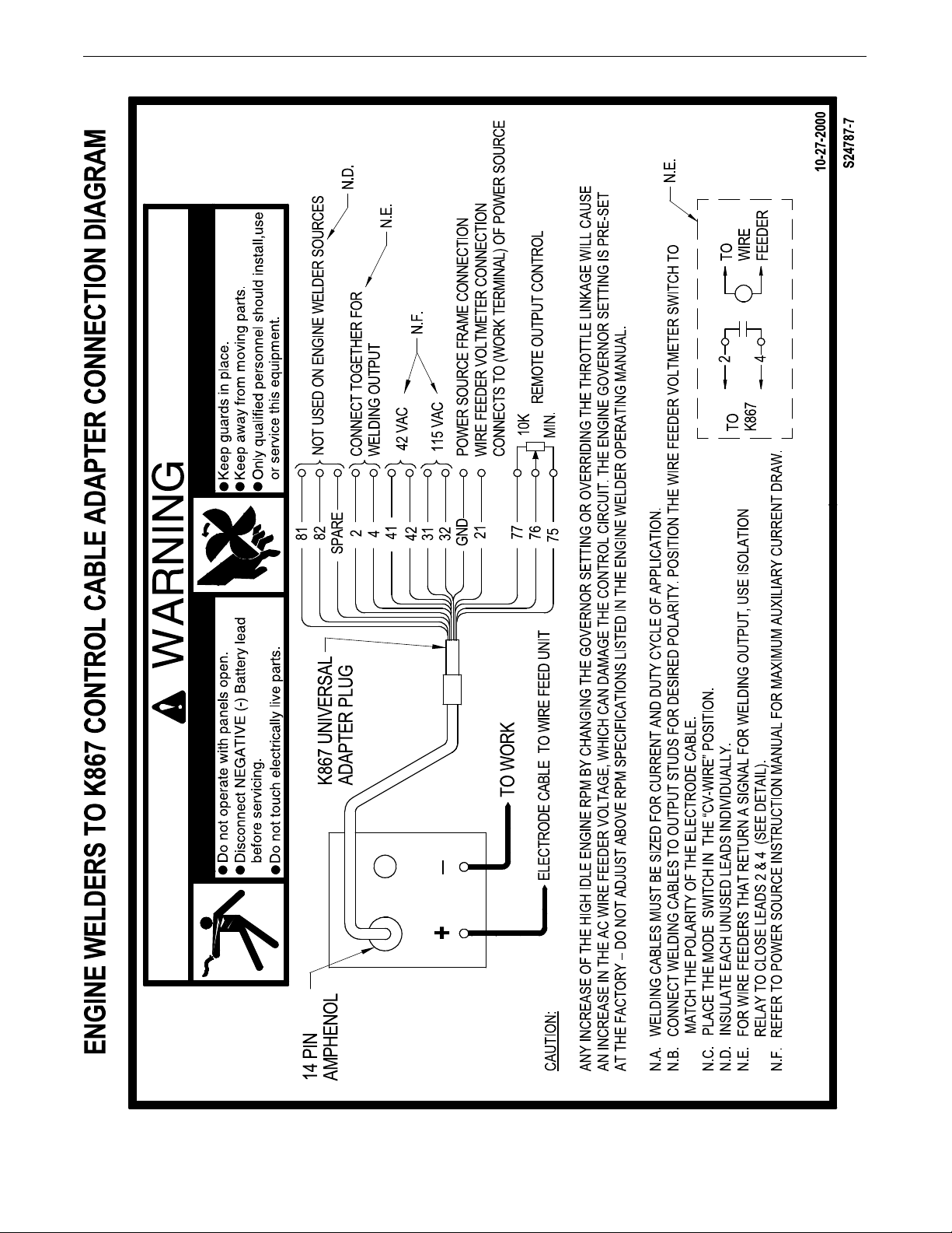
ANTAGE 400
V
DIAGRAMS
F-7
Page 45

ANTAGE 400
V
DIAGRAMS
F-8
Page 46

ANTAGE 400
2
9/03
V
DIAGRAMS
F-9
Page 47

ANTAGE 400
V
DIAGRAMS
F-10
Page 48

ANTAGE 400
V
DIAGRAMS
F-11
gram is illegible, write to the Service Department for a replacement. Give the equipment code number.
NOTE: This diagram is for reference only. It may not be accurate for all machines covered by this manual. The specific diagram for a particular code is included with the machine. If the dia-
Page 49

ANTAGE 400
VANTAGE 400 WIRING DIAGRAM CODES 11785, 11920, 12305, 12319
G7138
V
DIAGRAMS
gram is illegible, write to the Service Department for a replacement. Give the equipment code number.
NOTE: This diagram is for reference only. It may not be accurate for all machines covered by this manual. The specific diagram for a particular code is included with the machine. If the dia-
F-12
Page 50

ANTAGE 400
L12853
D
25.82
655.8
27.00
685.8
55.50
14091409..77
2.25
57.2
5.75
146.0
35.94
913.0
24.00
609.6
39.81
20.60
523.3
28.95
735.3
36.06
915.9
29.75
755.7
60.00
1524.0
11.25
285.8
N.A.
1.27
32.3
46.62
1184.15
N.A. CENTER OF GRAVITY WITH OIL IN ENGINE, COOLANT IN RADIATOR, AND EMPTY FUEL TANK.
N.B. CASEFRONT GRAPHICS MAY NOT MATCH ALL CODES.
V
DIAGRAMS
F-13
Page 51

Engine Driven Welders
Vantage
Vantage 400 (Perkins) - 12319
Index of Sub Assemblies - 12319........................................................................................1
Case Front & Control Panel Assembly ................................................................................3
Output Panel Assembly .......................................................................................................7
Power Module Panel Assembly.........................................................................................10
Generator & Rotor Assembly.............................................................................................12
Contents
Base, Fuel Tank & Battery Assembly ................................................................................14
Engine Assembly ...............................................................................................................18
Case Back & Radiator Asbly .............................................................................................21
Enclosure Components......................................................................................................23
i
Page 52

THIS PAGE INTENTIONALLY LEFT BLANK
ii
Page 53

Index of Sub Assemblies - 12319
KEY PART NUMBER DESCRIPTION QTY
P-590-A INDEX OF SUB ASSEMBLIES AR
1 P-590-C CASE FRONT & CONTROL PANEL ASSEMBLY AR
2 P-590-D OUTPUT PANEL ASSEMBLY AR
3 P-590-E POWER MODULE PANEL ASSEMBLY AR
4 P-590-F GENERATOR & ROTOR ASSEMBLY AR
5 P-590-G BASE FUEL TANK & BATTERY ASSEMBLY AR
6 P-590-H ENGINE ASSEMBLY AR
7 P-590-J CASE BACK & RADIATOR ASBLY AR
8 P-590-K ENCLOSURE COMPONENTS AR
Printed 07/11/2016 at 11:58:14. Produced by Enigma.
Vantage 400 (Perkins) - 12319 1
Page 54

Index of Sub Assemblies - 12319
P-590-A.jpg
2 Vantage 400 (Perkins) - 12319
Printed 07/11/2016 at 11:58:14. Produced by Enigma.
Page 55

Case Front & Control Panel Assembly
KEY PART NUMBER DESCRIPTION QTY
9SG4982-30 CONTROL PANEL ASBLY 1
1 9SG4867-1 CONTROL PANEL 1
9SS9262-27 PLAIN WASHER 2
9SCF000010 #10-24HN 4
9SE106A-1 LOCKWASHER 2
9SM19685-17 CONNECTOR & LEAD ASBLY 1
5B 9ST10491-1 KNOB 1
5C 9ST10491 KNOB 2
5D 9ST13483-7 O RING 011 3
9SM19685-10 CONNECTOR & LEAD ASBLY 1
6B 9SS12021-70 BOX RECEPTACLE SOLID SHELL 1
6C 9SS12021-68 CONNECTOR 1
6D 9SS17062-10 CABLE CONNECTOR CAP 1
6E 9SS17062-11 CABLE CONNECTOR CAP 1
9SS8025-96 SELF TAPPING SCREW 8
7 9SS17585-1 FUEL GAUGE 1
8 9SS25154-2 WATER TEMPERATURE GAUGE 1
9 9SS20206-2 OIL PRESSURE GAUGE 1
10 9ST13534-11 PILOT LIGHT 2
9SS24659 CATCH BRACKET 1
9SS8025-98 SELF TAPPING SCREW 2
12 9SS24691 PILOT LIGHT & TERMINAL 1
13 9SS17475-3 HOURMETER 1
14A 9ST10800-36 SWITCH-TOGGLEDPDT 1
9SS22061-4 SEALING BOOT 1
15 9SS13146-4 SWITCH-PUSH BUTTON 1
16 9SS13146-1 START BUTTON 1
17A 9ST10800-38 SWITCH-TOGGLE 2
9SS22061-4 SEALING BOOT 2
18A 9ST10800-39 SWITCH-TOGGLE 1
9SS22061-4 SEALING BOOT 1
19 9SG7105 DECAL CARRIER 1
20A 9SG5507-3 WELD CONTROL PC BD ASBLY 1
9SS8025-100 SELF TAPPING SCREW 4
Printed 07/11/2016 at 11:58:14. Produced by Enigma.
Vantage 400 (Perkins) - 12319 3
Page 56

Case Front & Control Panel Assembly
KEY PART NUMBER DESCRIPTION QTY
20C 9SL11924-1 PC BD MOUNTING BRKT 1
9ST9187-13 #10-24HLN-1817/1-NYLON INSERT 4
9SG6349 WIRING HARNESS 1
22A 9ST13637-6 DIODE-BRIDGE35A400VF-W1-PH 1
9SS10773-7 INSULATING WASHER 1
9SS9262-3 PLAIN WASHER 1
9SE106A-1 LOCKWASHER 1
9SCF000010 #10-24HN 1
24 9ST14659-1 FASTENER BUTTON 1
26 9ST10800-39 SWITCH-TOGGLE 1
30 9ST13534-3 PILOT LIGHT 1
K2467-1 DIGITAL WELD METER KIT 1
31A 9SL11160 METER HOUSING ASBLY 2
9SS24630 METER HOUSING SEAL 2
31E 9SM19368 METER BEZEL 2
31F 9ST14807-9 FILTER LENS 2
31G 9SCF000389 #4-40X.375SS-PPNHS-FULL-GR2-3147 4
9SS9262-3 PLAIN WASHER 4
9SCF000005 #6-32HN 4
32A 9SG4407-2 OCV INDICATOR PCB ASBLY 1
9ST9187-13 #10-24HLN-1817/1-NYLON INSERT 4
33 9SG7105 DECAL CARRIER 1
9SM19685-11 CONNECTOR & LEAD ASBLY 1
9SM21328-16 DOOR DECAL & LATCH ASBLY 1
35A 9SL12440 FLIP DOWN DOOR ASBLY 1
35B 9SG7105 DECAL CARRIER 1
35C 9SS25569 DOOR PADDLE LATCH 1
9SS9225-68 THREAD FORMING SCREW (CUTTING) 4
38A 9ST12287-20 CIRCUIT BREAKER-10A250VAC 2
38B 9SS22061-3 SEALING BOOT 2
9SS9225-68 THREAD FORMING SCREW (CUTTING) 4
9SL13117 CASE FRONT & INSERT ASBLY 1
43A 9SG4865 CASEFRONT 1
9SS9225-68 THREAD FORMING SCREW (CUTTING) 6
4 Vantage 400 (Perkins) - 12319
Printed 07/11/2016 at 11:58:14. Produced by Enigma.
Page 57

Case Front & Control Panel Assembly
KEY PART NUMBER DESCRIPTION QTY
43C 9SG4870 CASEFRONT INSERT 1
9SS9225-68 THREAD FORMING SCREW (CUTTING) 4
9SM17238 INSTRUCTION TAG 1
45 9SG6048 SHIELD 1
Printed 07/11/2016 at 11:58:14. Produced by Enigma.
Vantage 400 (Perkins) - 12319 5
Page 58

Case Front & Control Panel Assembly
P-590-C.jpg
6 Vantage 400 (Perkins) - 12319
Printed 07/11/2016 at 11:58:14. Produced by Enigma.
Page 59

Output Panel Assembly
KEY PART NUMBER DESCRIPTION QTY
9SG4983-27 OUTPUT PANEL ASSEMBLY 1
1A 9SG4866-12 WELD OUTPUT PANEL 1
9SS9262-27 PLAIN WASHER 2
9SCF000010 #10-24HN 4
9SE106A-1 LOCKWASHER 2
5A 9SS11668-2 RECEPTACLE DUPLEX 120VAC 20A 2
5B 9SS27290 COVER RECEPTACLE DUPLEX 2
5C 9SL13286 GFCI HOUSING 2
5D 9SS27167 MOUNTING BRACKET 2
5E 9SS24738-3 THERMOPLASTIC SCREW 4
7 9ST12287-38 CIRCUIT BREAKER 2
8 9SS22061-2 SEALING BOOT 2
9 9SG7105 DECAL CARRIER 1
10A 9SM13900 OUTPUT TERMINAL ASBLY 2
10B 9SS8025-91 SELF TAPPING SCREW 4
11A 9SM20007 OUTPUT STUD COVER 2
11B 9SS25669 OUTPUT STUD COVER PLATE 2
11C 9SS9225-68 THREAD FORMING SCREW (CUTTING) 4
12A 9ST9187-1 1/4-20HJLN 1
12B 9SCF000017 1/4-20HN 1
13A 9SS18907-3 RECEPTACLE 250v 50A 1
13B 9SM18861 RECEPTACLE COVER 1
9ST9695-3 LOCKWASHER 4
9SCF000042 #8-32HN 4
14A 9SM20586-1 CIRCUIT BREAKER50A3 POLE 1
14B 9SS24911-4 CIRCUIT BREAKER COVER 1
9ST10082-30 SEMS SCREW 6
9ST4291-A LOCKWASHER 6
15A 9SS18907-2 RECEPTACLE-SINGLE 1
15B 9SM18861 RECEPTACLE COVER 1
9ST9695-3 LOCKWASHER 4
9SCF000042 #8-32HN 4
21 9SG7105 DECAL CARRIER 1
K3157-1 GFCI KIT 1
Printed 07/11/2016 at 11:58:14. Produced by Enigma.
Vantage 400 (Perkins) - 12319 7
Page 60

Output Panel Assembly
KEY PART NUMBER DESCRIPTION QTY
22A 9SS26843-1 GFCI REWORK 2
22B 9SS28464 GFCI COVER 2
22C 9SL13286 GFCI HOUSING 2
22D 9SS27167 MOUNTING BRACKET 2
9SS24738-3 THERMOPLASTIC SCREW 4
9SS9225-68 THREAD FORMING SCREW (CUTTING) 4
9SS24097-2 SHUNT & LEAD ASBLY 1
9SCF000344 HEX HD SCREW 2
9SE106A-15 LOCKWASHER 2
9SS9262-1 PLAIN WASHER 2
8 Vantage 400 (Perkins) - 12319
Printed 07/11/2016 at 11:58:14. Produced by Enigma.
Page 61

Output Panel Assembly
P-590-D.jpg
Printed 07/11/2016 at 11:58:14. Produced by Enigma.
Vantage 400 (Perkins) - 12319 9
Page 62

Power Module Panel Assembly
KEY PART NUMBER DESCRIPTION QTY
9SG5011-1 POWER MODULE PANEL ASSEMBLY 1
1 9SG4930-1 POWER MODULE PANEL 1
2A 9SG4932-1 FUEL TANK FRONT PANEL 1
2B 9SS9225-68 THREAD FORMING SCREW (CUTTING) 1
3 9ST12380-4 BUSHING 1
4A 9SS26006-1 CHOPPER BRACKET 2
4B 9SS9225-68 THREAD FORMING SCREW (CUTTING) 4
5A 9SL12683-1 CHOPPER HEAT SINK 1
9SS25930-6 TORX BUTTON HEAD SCREW 1/4-20X.62 4
9SE106A-2 LOCKWASHER 4
7A 9SS10404-138 RESISTOR-WW100W505% 1
7B 9SCF000191 #10-24X7.50RHS 1
7C 9SS9262-27 PLAIN WASHER 2
9SE106A-1 LOCKWASHER 1
7E 9SCF000010 #10-24HN 1
8A 9SS22168 HEAT SINK HOLDER 2
8B 9SS9225-45 THREAD FORMING SCREW 2
9A 9SL11132-2 THREE PHASE BRIDGE RECTIFIER 1
9SS9262-121 PLAIN WASHER 2
9SE106A-14 LOCKWASHER 2
9SS9225-68 THREAD FORMING SCREW (CUTTING) 4
16A 9SL12400-3V1 IDLER/ENGINE SHUTDOWN PC BD ASBLY 1
16B 9SS8025-100 SELF TAPPING SCREW 4
10 Vantage 400 (Perkins) - 12319
Printed 07/11/2016 at 11:58:14. Produced by Enigma.
Page 63

Power Module Panel Assembly
P-590-E.jpg
Printed 07/11/2016 at 11:58:14. Produced by Enigma.
Vantage 400 (Perkins) - 12319 11
Page 64

Generator & Rotor Assembly
KEY PART NUMBER DESCRIPTION QTY
9SL10742-15 GENERATOR ASBLY 1
1 9SG3088-16 STATOR TIE BAR ASBLY 1
9SL13110-3 ROTOR & COUPLING DISC ASBLY 1
2B 9SL10501-5 ROTOR & SHAFT ASBLY 1
2C 9SM19796 COUPLING DISC 1
9SS8042 COUPLING DISC BACKING PLATE 2
2E 9SS14233 COUPLING CLAMP RING-INSIDE 1
2F 9ST8833-2 HEX HD CAP SCREW 8
2G 9SE106A-8 LOCKWASHER 8
3A 9SS22657 FAN COUPLE 1
3B 9SCF000025 3/4-10HN 1
3C 9SE106A-7 LOCKWASHER 1
4A 9SL9551 FAN BLADE 1
4B 9SS9225-22 THREAD FORMING SCREW (ROLLING) 4
4C 9SE106A-14 LOCKWASHER 4
5A 9SM9300-85 BEARING 1
5B 9SS18044-5 TOLERANCE RING 1
9A 9SS11868-1 BLOWER SEGMENT 4
9B 9ST14731-61 METRIC SOCKET HD SCREW-M10 X 1.25 SS 8
9C 9SS17400-1 LOCKWASHER-METRIC 8
9ST8833-10 HEX HD CAP SCREW 8
9SE106A-16 LOCKWASHER 8
15A 9ST8833-86 HEX HD CAP SCREW 2
15B 9SE106A-16 LOCKWASHER 2
15C 9SS9262-120 PLAIN WASHER 2
16A 9SM16158 BRUSH & BRUSH HOLDER ASBLY 1
9SG2114 BRUSH HOLDER CARTRIDGE 1
9SS19480 BRUSH ASBLY 2
9SM16157 BRUSH ASBLY RETAINER 1
16B 9SM18323 BRUSH HOLDER BRKT 1
9SS9225-8 THREAD FORMING SCREW (ROLLING) 2
9SS8025-91 SELF TAPPING SCREW 2
16E 9ST12380-4 BUSHING 1
12 Vantage 400 (Perkins) - 12319
Printed 07/11/2016 at 11:58:14. Produced by Enigma.
Page 65

Generator & Rotor Assembly
P-590-F.jpg
Printed 07/11/2016 at 11:58:14. Produced by Enigma.
Vantage 400 (Perkins) - 12319 13
Page 66

Base, Fuel Tank & Battery Assembly
KEY PART NUMBER DESCRIPTION QTY
1 9SG4900-4 BASE 1
2A 9SM20610 MOUNTING BRACKET 4
2B 9SS9225-64 SELF TAPPING SCREW 8
3A 9SL12454-11 STATOR SUPPORT 1
9SS9225-64 SELF TAPPING SCREW 16
3C 9SL12454-12 SUPPORT 1
5A 9ST11991-2 RUBBER MOUNTING 4
9SS9225-64 SELF TAPPING SCREW 8
7A 9SM9399-11 BATTERY 1
7B 9SS8070-51 BATTERY CABLE (NEGATIVE) 1
7C 9SS8070-47 BATTERY CABLE 1
9ST14815-2 METRIC HEX NUT-M8 X 1.25 BRASS 1
7E 9SS20191-1 BATTERY TERMINAL COVER 1
9SE106A-14 LOCKWASHER 1
9SS9262-121 PLAIN WASHER 1
8A 9SM20535 BATTERY TRAY 1
8B 9SS22018 BATTERY BRKT 1
8C 9ST11827-31 CARRIAGE BOLT 2
8D 9ST9187-6 LOCKNUT 2
8E 9ST14654 CAP-PLASTIC 1
9SS9225-68 THREAD FORMING SCREW (CUTTING) 4
9SG6071 FUEL TANK ASSEMBLY 1
10A 9SG6058 FUEL TANK 1
10B 9SL12505 FUEL SENDER 1
10C 9SS19564-1 FUEL FITTING (PUSH-IN) 1
10D 9SS19563 RUBBER PLUG 2
10E 9SS20541 FUEL CAP 1
10F 9SS19564-5 FUEL FITTINGPUSH-IN 1
9SL13304 FUEL TANK TRAY 1
15A 9SL12457 SUPPORT RAIL 2
9SS9225-68 THREAD FORMING SCREW (CUTTING) 4
16A 9SM20547 CHOKE BRACKET 1
16B 9SM19416-2 CHOKE ASBLY 1
16C 9SCF000187 5/16-18X2.50HHCS 2
14 Vantage 400 (Perkins) - 12319
Printed 07/11/2016 at 11:58:14. Produced by Enigma.
Page 67

Base, Fuel Tank & Battery Assembly
KEY PART NUMBER DESCRIPTION QTY
16D 9SS9262-121 PLAIN WASHER 2
16E 9SE106A-14 LOCKWASHER 2
16F 9SCF000029 5/16-18HN 2
9SS9225-68 THREAD FORMING SCREW (CUTTING) 4
18A 9ST10642-231 FLEX TUBE 1
18B 9SS10888-35 HOSE CLAMP 2
19A 9ST10642-111 FLEX TUBE 1
19B 9ST13777-5 HOSE CLAMP 2
20A 9SG6084 LIFT BALE FRAME 1
9ST8833-24 HEX HD CAP SCREW 4
9SE106A-15 LOCKWASHER 4
9SCF000027 1/2-13HN 4
21A 9SS10227-61 LIFT BALE 1
9ST8833-24 HEX HD CAP SCREW 4
9SE106A-15 LOCKWASHER 4
9SCF000027 1/2-13HN 4
25A 9SL12458-1 FAN GUARD 1
25B 9SL12485 STATOR FAN SHROUD 1
9SS9225-68 THREAD FORMING SCREW (CUTTING) 8
26A 9SL10121-1 BYPASS/STABILIZER PC BD ASBLY 1
26B 9SS14020-3 PLASTIC EXPANSION NUT 3
26C 9SS8025-97 SELF TAPPING SCREW 3
28A 9SCF000014 1/4-20X.75HHCS 2
28B 9SS9262-98 PLAIN WASHER 2
28C 9SE106A-2 LOCKWASHER 2
28D 9SCF000017 1/4-20HN 2
29A 9SS13490-171A FILTER CAPACITOR 1
29B 9SS22747 CAPACITOR BRKT ASBLY 1
9SS9225-68 THREAD FORMING SCREW (CUTTING) 1
9SS11604-65 SET SCREW 2
30A 9SM20007 OUTPUT STUD COVER 1
30B 9SS25669 OUTPUT STUD COVER PLATE 1
30C 9SS9225-68 THREAD FORMING SCREW (CUTTING) 2
35A 9SM20612 CONTAINER BRACKET 1
Printed 07/11/2016 at 11:58:14. Produced by Enigma.
Vantage 400 (Perkins) - 12319 15
Page 68

Base, Fuel Tank & Battery Assembly
KEY PART NUMBER DESCRIPTION QTY
35B 9SS9225-68 THREAD FORMING SCREW (CUTTING) 2
36A 9SL12515-1 SIDE PANEL 1
9SS24739-27 1/4X.75 TEK SCREW 3
40 9SM16197 DECAL-WARNING 1
41 9SS17851 DECAL-CAUTION 1
9ST14882-1 DOOR BUMPER 2
16 Vantage 400 (Perkins) - 12319
Printed 07/11/2016 at 11:58:14. Produced by Enigma.
Page 69

Base, Fuel Tank & Battery Assembly
P-590-G.jpg
Printed 07/11/2016 at 11:58:14. Produced by Enigma.
Vantage 400 (Perkins) - 12319 17
Page 70

Engine Assembly
KEY PART NUMBER DESCRIPTION QTY
9SG6063-4 ENGINE ASSEMBLY 1
1 9SM25304 ENGINE 1
2B 9SM20808 SOLENOID BRACKET 1
9ST14731-31 METRIC HEX HD SCREW-M8 X1.25 2
9SE106A-3 LOCKWASHER 2
9ST10642-86 FLEX TUBE 1
9ST13777-1 HOSE CLAMP 2
6A 9SL10878-2 MUFFLER ASBLY 1
9ST14731-11 METRIC HEX HD SCREW-M8 X1.25 4
9SE106A-3 LOCKWASHER 4
7A 9SS24739-31 1/4-20 STAINLESS STEEL SCREW 1
7B 9SE106A-2 LOCKWASHER 1
8A 9SS20140-2 SOLENOID ASBLY 1
9SS9225-66 SELF TAPPING SCREW 2
8C 9SS22070 IN-LINE SWIVEL 1
8D 9SCF000060 1/4-28HJN 4
8E 9SS22232 ROD END SWIVEL 1
8F 9SE106A-2 LOCKWASHER 5
8G 9SS26305-1 SOLENOID LINKAGE 1
9ST8833-54 HEX HD CAP SCREW 1
9ST10642-278 FLEX TUBE 1
9SS10888-27 HOSE CLAMP 1
10A 9SM25295 ENGINE FOOT WELDED ASBLY 2
9SS19959-1 METRIC HEX LOCK NUT 1
9ST14815-4 METRIC HEX NUT-M5 X 0.8 1
9SE106A-1 LOCKWASHER 1
12A 9SM20827 UPPER RADIATOR HOSE 1
9SM20828 LOWER RADIATOR HOSE 1
9SS10888-16 HOSE CLAMP 2
13A 9SM20840 FUEL PRE-FILTER/WATER SEPARATOR 1
9SM20840-A WATER SEPARATOR ELEMENT SET 1
9SCF000073 5/16-18X2.75HHCS 1
9SE106A-14 LOCKWASHER 1
9SCF000029 5/16-18HN 1
18 Vantage 400 (Perkins) - 12319
Printed 07/11/2016 at 11:58:14. Produced by Enigma.
Page 71

Engine Assembly
KEY PART NUMBER DESCRIPTION QTY
9ST8833-86 HEX HD CAP SCREW 2
9SE106A-16 LOCKWASHER 2
9SS9262-120 PLAIN WASHER 2
16A 9SM20358 AIR FILTER 1
16B 9SM20501 AIR INTAKE HOSE 1
9SS10888-29 HOSE CLAMP 2
9SM20359 AIR FILTER MTG BAND 1
9SCF000028 5/16-18X1.25HHCS 2
9SS9262-121 PLAIN WASHER 2
9SE106A-14 LOCKWASHER 2
9SCF000029 5/16-18HN 2
9SM20807 AIR CLEANER BRACKET 1
9SS24739-31 1/4-20 STAINLESS STEEL SCREW 3
17A 9SS26772 LIFT EYE 1
9SE106A-3 LOCKWASHER 1
9ST14731-31 METRIC HEX HD SCREW-M8 X1.25 1
Printed 07/11/2016 at 11:58:14. Produced by Enigma.
Vantage 400 (Perkins) - 12319 19
Page 72

Engine Assembly
P-590-H.jpg
20 Vantage 400 (Perkins) - 12319
Printed 07/11/2016 at 11:58:14. Produced by Enigma.
Page 73

Case Back & Radiator Asbly
KEY PART NUMBER DESCRIPTION QTY
1A 9SL13118-9 CASE BACK & RADIATOR ASBLY 1
9SG4901-10 CASE BACK 1
9SG3115-6 RADIATOR 1
9SM15045-80 ACOUSTICAL FOAM 2
9SG6916-2 FAN SHROUD 1
9SS9225-26 THREAD FORMING SCREW (ROLLING) 4
9SE106A-14 LOCKWASHER 4
9ST11827-71 CARRIAGE BOLT 4
9SS30690 SPACER 4
9SS30686 ISOLATOR 4
9SM25275 MOUNTING BRACKET 2
9SS9262-47 PLAIN WASHER 4
9ST9187-10 3/8-16HLN-1817/1-NYLON INSERT 4
9ST10642-218 FLEX HOSE 1
9SS10888-35 HOSE CLAMP 3
9SS24068 FUEL SHUT-OFF 1
9ST10642-333 FLEX TUBE 1
10A 9SG4058-10 LEFT FAN GUARD 1
9SS9225-68 THREAD FORMING SCREW (CUTTING) 6
11A 9SG4060-10 FAN GUARD 1
9SS9225-68 THREAD FORMING SCREW (CUTTING) 5
15 9SG7105 DECAL CARRIER 1
16 9SS26354 ENGINE SERVICE DECAL 1
17 9ST13086-62 DECAL-WARNING 1
18 9SM20358-1 AIR SERVICE DECAL 1
9ST14882 DOOR BUMPER 1
Printed 07/11/2016 at 11:58:14. Produced by Enigma.
Vantage 400 (Perkins) - 12319 21
Page 74

Case Back & Radiator Asbly
P-590-J.jpg
22 Vantage 400 (Perkins) - 12319
Printed 07/11/2016 at 11:58:14. Produced by Enigma.
Page 75

Enclosure Components
KEY PART NUMBER DESCRIPTION QTY
1A 9SG4902-1 ROOF 1
1B 9SS24739-27 1/4X.75 TEK SCREW 13
1C 9SL12084 FUEL TROUGH 1
9SM20278 RADIATOR CAP COVER ASSEMBLY 1
2A 9SS25717 RADIATOR CAP COVER 1
2B 9SS21250-19 HINGE - STAINLESS STEEL 1
2C 9SS24694 LATCH 1
9ST12584-9 RIVET 2
2E 9ST14882 DOOR BUMPER 2
9ST12584-6 RIVET 2
3A 9SG4903 LEFT CASE SIDE 1
9SS24739-27 1/4X.75 TEK SCREW 11
4A 9SG4904 RIGHT CASE SIDE 1
4B 9SS24739-27 1/4X.75 TEK SCREW 7
5A 9ST14882-1 DOOR BUMPER 2
9ST12584-6 RIVET 2
7A 9SL12516-1 DOOR SLIDE 1
7B 9SS24739-27 1/4X.75 TEK SCREW 12
7C 9SS25719-2 EDGE GUARD 2
9SL13813 DOOR ASBLY 1
8A 9SL12513-1 DOOR 1
8B 9SS25698 DOOR HOOK 2
8C 9SM20241 DOOR LATCH 1
8D 9ST12584-6 RIVET 4
9ST14882-2 DOOR BUMPER 2
9ST12584-6 RIVET 2
9ST14882 DOOR BUMPER 2
8H 9SS27368-6 LOGO DECAL 1
8J 9SM21801 FAMILY NAME LOGO 1
10 9ST13086-205 FUEL WARNING DECAL 1
11 9SS12934-1 COVER SEAL 1
12 9SS25896 DECAL-WARNING 1
13 9SS27368-6 LOGO DECAL 1
15 9ST14882-1 DOOR BUMPER 2
Printed 07/11/2016 at 11:58:14. Produced by Enigma.
Vantage 400 (Perkins) - 12319 23
Page 76

Enclosure Components
KEY PART NUMBER DESCRIPTION QTY
17 9SM21801 FAMILY NAME LOGO 1
20 9SM21436 CARBON MONOXIDE WARNING DECAL 1
21 9SS30277-3 WARRANTY DECAL 1
22 9SS28039-1 DECAL GREEN INITIATIVE 1
24 Vantage 400 (Perkins) - 12319
Printed 07/11/2016 at 11:58:14. Produced by Enigma.
Page 77
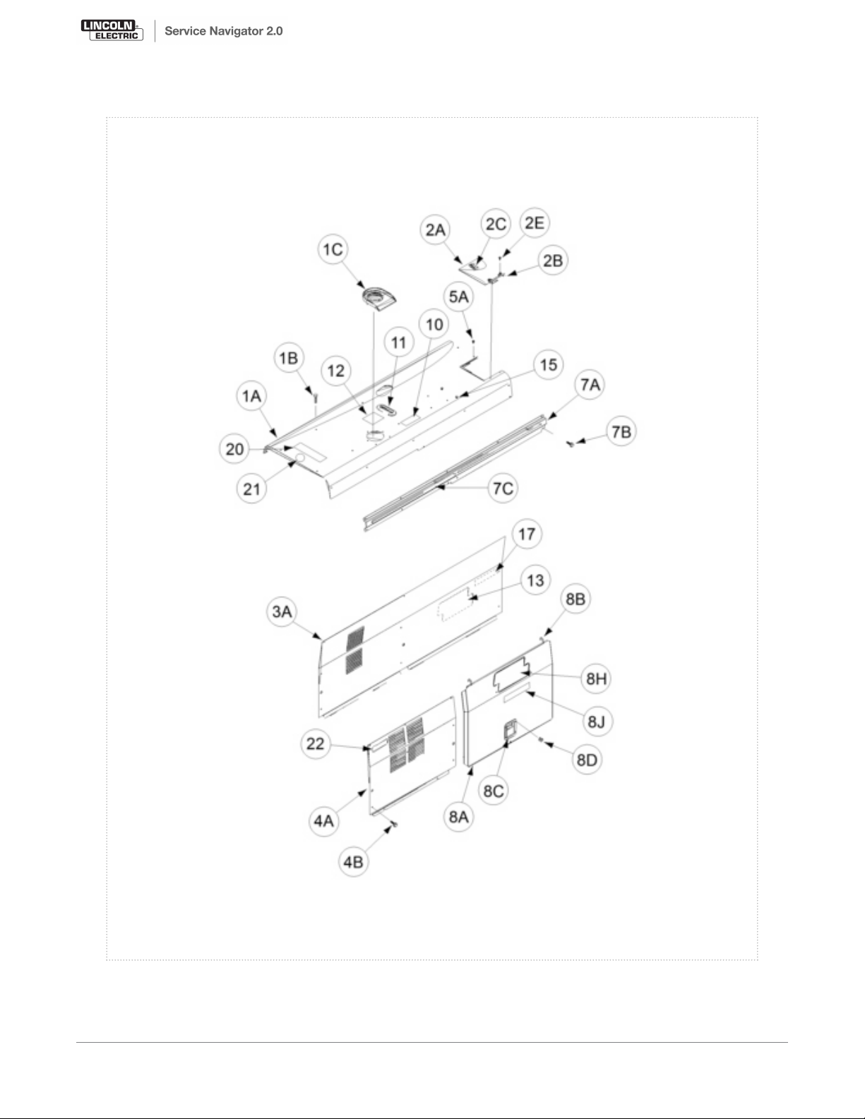
Enclosure Components
P-590-K.jpg
Printed 07/11/2016 at 11:58:14. Produced by Enigma.
Vantage 400 (Perkins) - 12319 25
Page 78
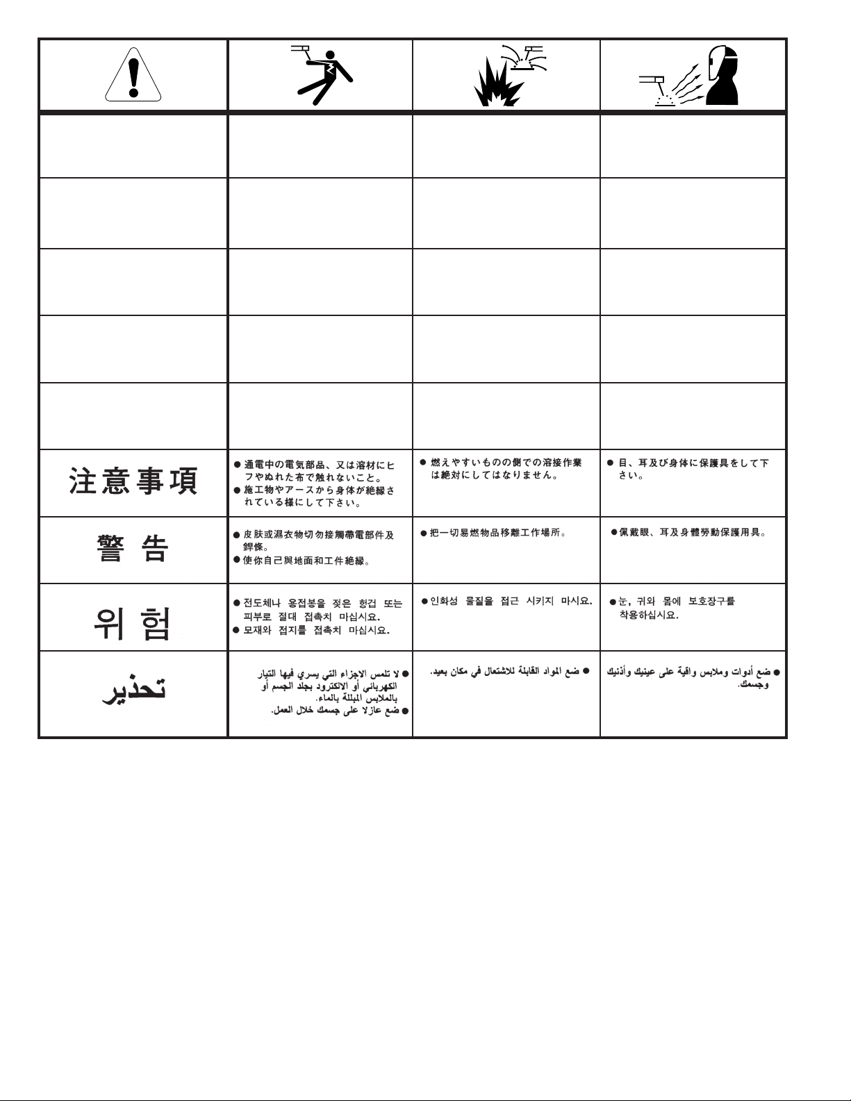
WARNING
panish
S
AVISO DE
PRECAUCION
French
ATTENTION
erman
G
WARNUNG
ortuguese
P
ATENÇÃO
Japanese
Chinese
l Do not touch electrically live parts or
electrode with skin or wet clothing.
l Insulate yourself from work and
ground.
l
No toque las partes o los electrodos
bajo carga con la piel o ropa mojada.
l Aislese del trabajo y de la tierra.
l Ne laissez ni la peau ni des vête-
ments mouillés entrer en contact
avec des pièces sous tension.
l
Isolez-vous du travail et de la terre.
l Berühren Sie keine stromführenden
Teile oder Elektroden mit Ihrem
Körper oder feuchter Kleidung!
l Isolieren Sie sich von den
Elektroden und dem Erdboden!
l Não toque partes elétricas e elec-
trodos com a pele ou roupa molhada.
l
Isole-se da peça e terra.
l Keep flammable materials away.
l
Mantenga el material combustible
fuera del área de trabajo.
l
Gardez à l’écart de tout matériel
inflammable.
l Entfernen Sie brennbarres Material!
l
Mantenha inflamáveis bem guardados.
l Wear eye, ear and body protection.
l
Protéjase los ojos, los oídos y el
cuerpo.
l
Protégez vos yeux, vos oreilles et
votre corps.
l Tragen Sie Augen-, Ohren- und Kör-
perschutz!
l
Use proteção para a vista, ouvido e
corpo.
Korean
Arabic
READ AND UNDERSTAND THE MANUFACTURER’S INSTRUCTION FOR THIS EQUIPMENT AND THE CONSUMABLES TO BE
USED AND FOLLOW YOUR EMPLOYER’S SAFETY PRACTICES.
SE RECOMIENDA LEER Y ENTENDER LAS INSTRUCCIONES DEL FABRICANTE PARA EL USO DE ESTE EQUIPO Y LOS
CONSUMIBLES QUE VA A UTILIZAR, SIGA LAS MEDIDAS DE SEGURIDAD DE SU SUPERVISOR.
LISEZ ET COMPRENEZ LES INSTRUCTIONS DU FABRICANT EN CE QUI REGARDE CET EQUIPMENT ET LES PRODUITS A
ETRE EMPLOYES ET SUIVEZ LES PROCEDURES DE SECURITE DE VOTRE EMPLOYEUR.
LESEN SIE UND BEFOLGEN SIE DIE BETRIEBSANLEITUNG DER ANLAGE UND DEN ELEKTRODENEINSATZ DES HERSTELLERS. DIE UNFALLVERHÜTUNGSVORSCHRIFTEN DES ARBEITGEBERS SIND EBENFALLS ZU BEACHTEN.
Page 79
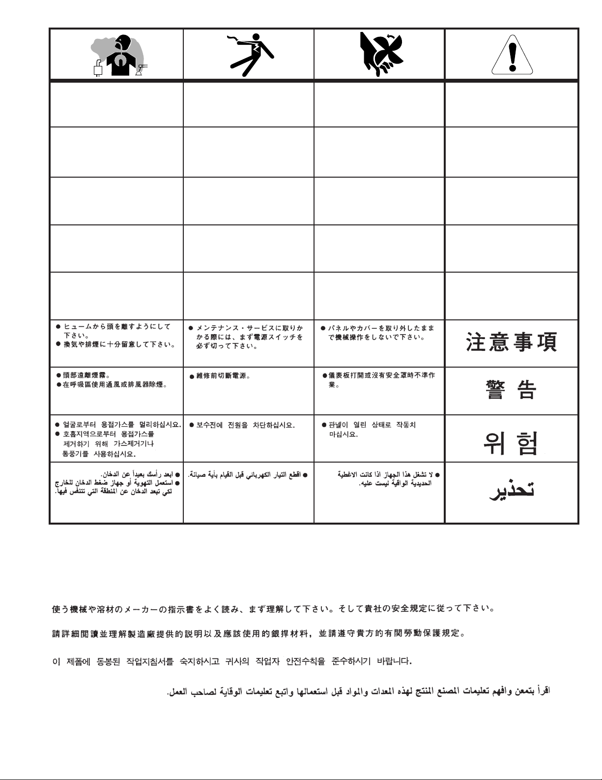
l Keep your head out of fumes.
l Use ventilation or exhaust to
remove fumes from breathing zone.
l Turn power off before servicing.
l Do not operate with panel open or
guards off.
WARNING
l Los humos fuera de la zona de res-
piración.
l Mantenga la cabeza fuera de los
humos. Utilice ventilación o
aspiración para gases.
l Gardez la tête à l’écart des fumées.
l Utilisez un ventilateur ou un aspira-
teur pour ôter les fumées des zones
de travail.
l
Vermeiden Sie das Einatmen von
Schweibrauch!
l Sorgen Sie für gute Be- und
Entlüftung des Arbeitsplatzes!
l Mantenha seu rosto da fumaça.
l Use ventilação e exhaustão para
remover fumo da zona respiratória.
l Desconectar el cable de ali-
mentación de poder de la máquina
antes de iniciar cualquier servicio.
l Débranchez le courant avant l’entre-
tien.
l
Strom vor Wartungsarbeiten
abschalten! (Netzstrom völlig öffnen; Maschine anhalten!)
l Não opere com as tampas removidas.
l Desligue a corrente antes de fazer
serviço.
l
Não toque as partes elétricas nuas.
l No operar con panel abierto o
guardas quitadas.
l N’opérez pas avec les panneaux
ouverts ou avec les dispositifs de
protection enlevés.
l
Anlage nie ohne Schutzgehäuse
oder Innenschutzverkleidung in
Betrieb setzen!
l
Mantenha-se afastado das partes
moventes.
l Não opere com os paineis abertos
ou guardas removidas.
Spanish
AVISO DE
PRECAUCION
rench
F
ATTENTION
German
WARNUNG
ortuguese
P
ATENÇÃO
Japanese
Chinese
Korean
Arabic
LEIA E COMPREENDA AS INSTRUÇÕES DO FABRICANTE PARA ESTE EQUIPAMENTO E AS PARTES DE USO, E SIGA AS
PRÁTICAS DE SEGURANÇA DO EMPREGADOR.
Page 80

CUSTOMER ASSISTANCE POLICY
The business of The Lincoln Electric Company is manufacturing and
selling high quality welding equipment, consumables, and cutting
equipment. Our challenge is to meet the needs of our customers and
to exceed their expectations. On occasion, purchasers may ask
incoln Electric for advice or information about their use of our
L
products. We respond to our customers based on the best information
in our possession at that time. Lincoln Electric is not in a position to
warrant or guarantee such advice, and assumes no liability, with
respect to such information or advice. We expressly disclaim any
warranty of any kind, including any warranty of fitness for any
customer’s particular purpose, with respect to such information or
advice. As a matter of practical consideration, we also cannot assume
any responsibility for updating or correcting any such information or
advice once it has been given, nor does the provision of information
or advice create, expand or alter any warranty with respect to the sale
of our products.
Lincoln Electric is a responsive manufacturer, but the selection and
use of specific products sold by Lincoln Electric is solely within the
control of, and remains the sole responsibility of the customer. Many
variables beyond the control of Lincoln Electric affect the results
obtained in applying these types of fabrication methods and service
requirements.
Subject to Change – This information is accurate to the best of our
knowledge at the time of printing. Please refer to
www.lincolnelectric.com for any updated information.
TABLE OF CONTENTS
INSTALLATION
PERATION
O
ACCESSORIES
MAINTENANCE
TROUBLE SHOOTING
DIAGRAMS
 Loading...