

Page 1
Operator’s Manual
INVERTEC ® V205-T DC & V205-T AC/DC
Register your machine:
www.lincolnelectric.com/register
Authorized Service and Distributor Locator:
www.lincolnelectric.com/locator
IM937 | Issue D ate Jan- 14
© Lincoln Global, Inc. All Rights Reserved.
For use with machines having Code Numbers:
11426, 11430
I
N
V
E
R
I
N
V
E
R
T
E
C
V
2
0
5
-
T
T
E
C
V
2
0
5
-
T
A
C
/D
C
A
C
/D
C
Save for future reference
Date Purchased
Code: (ex: 10859)
Serial: (ex: U1060512345)
Page 2
THANK YOU FOR SELECTING
A QUALITY PRODUCT BY
LINCOLN ELEC TRIC.
!
"
When this equipment is shipped, title passes to the purchaser upon
receipt by the carrier. Consequently, Claims for material damaged in
shipment must be made by the purchaser against the transportation
company at the time the shipment is received.
""
Lincoln arc welding and cutting equipment is designed and built with
safety in mind. However, your overall safety can be increased by
proper installation ... and thoughtful operation on your part.
DO NOT INSTALL, OPERATE OR REPAIR THIS EQUIPMENT
WITHOUT READING THIS MANUAL AND THE SAFETY PRECAUTIONS
CONTAINED THROUGHOUT. And, most importantly, think before you
act and be careful.
This statement appears where the information must be followed
exactly to avoid serious personal injury or loss of life.
This statement appears where the information must be followed to
avoid minor personal injury or damage to this equipment.
"
DON’T get too close to the arc. Use
c
orrective lenses if necessary to
stay a reasonable distance away
from the arc.
READ and obey the Material Safety
Data Sheet (MSDS) and the warning
label that appears on all containers
of welding materials.
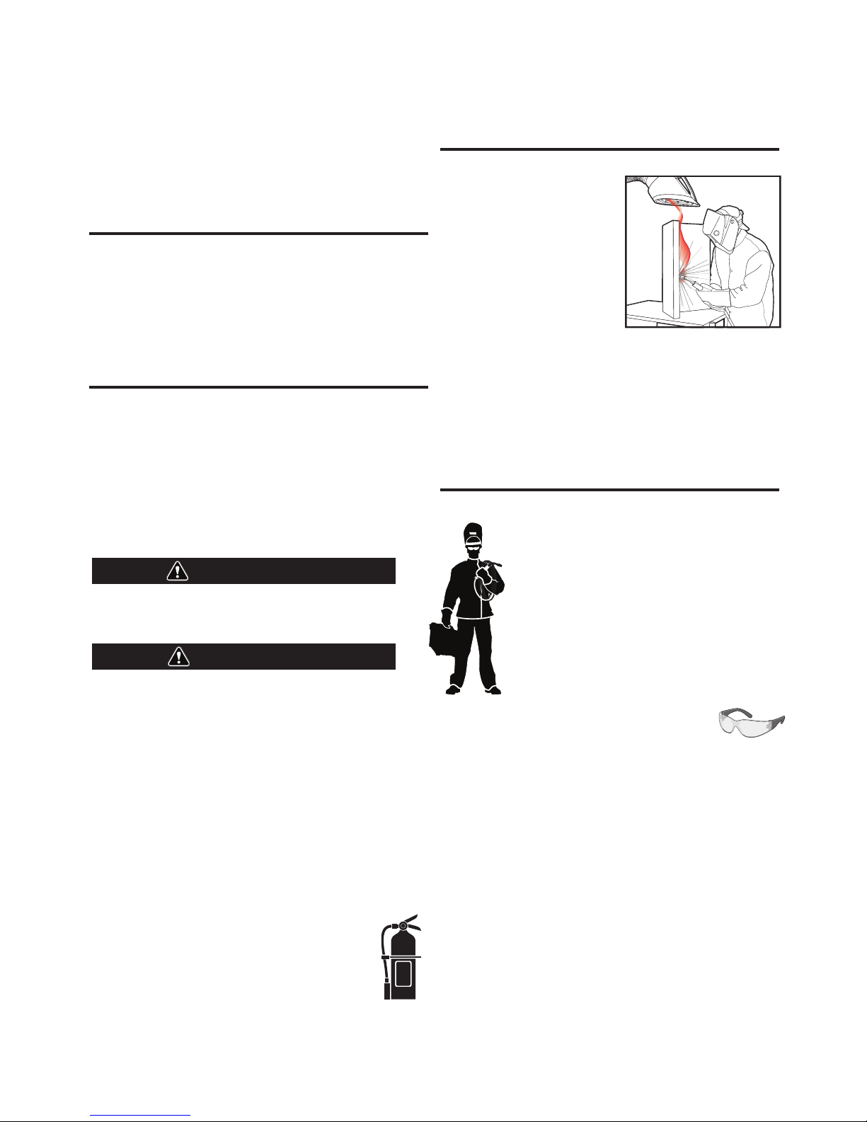
USE ENOUGH VENTILATION or
exhaust at the arc, or both, to keep
the fumes and gases from your breathing zone and the general area.
IN A LARGE ROOM OR OUTDOORS, natural ventilation may be
adequate if you keep your head out of the fumes (See below).
USE NATURAL DRAFTS or fans to keep the fumes away from your
face.
If you de velop unusual symptoms, see your supervisor. Perhaps the
welding atmosphere and ventilation system should be checked.
""
PROTECT your eyes and face with welding helmet
properly fitted and with proper grade of filter plate
(See ANSI Z49.1).
PROTECT your body from welding spatter and arc
flash with protective clothing including woolen
clothing, flame-proof apron and gloves, leather
leggings, and high boots.
PROTECT others from splatter, flash, and glare with
protective screens or barriers.
IN SOME AREAS, protection from noise may be
appropriate.
BE SURE protective equipment is in good condition.
Also, wear safety glasses in work area
AT ALL
TIMES.
SPECIA L SI TUATIONS
DO NOT WELD OR CUT containers or materials which previously had
been in contact with hazardous substances unless they are properly
cleaned. This is extremely dangerous.
DO NOT WELD OR CUT painted or plated parts unless special
precautions with ventilation have been taken. They can release highly
toxic fumes or gases.
Additional precautionary measures
PROTECT compressed gas cylinders from excessive heat, mechanical
shocks, and arcs; fasten cylinders so they cannot fall.
BE SURE cylinders are never grounded or part of an electrical circuit.
REMOVE all potential fire hazards from welding area.
ALWAYS HAVE FIRE FIGHTING EQUIPMENT READY FOR
IMMEDIATE USE AND KNOW HOW TO USE IT.
WARNING
CAUTION
Page 3
SECTION A:
WARNINGS
CALIFORNIA PROPOSITION 65 WARNINGS
Diesel Engines
Diesel engine exhaust and some of its constituents are known
to the State of California to cause cancer, birth defects, and other
reproductive harm.
Gasoline Engines
The engine exhaust from this product contains chemicals known
to the State of California to cause cancer, birth defects, or other
reproductive harm.
#
"
" "
Read and understand the following safety highlights. For additional
safety information, it is strongly recommended that you purchase a
copy of “Safety in Welding & Cutting - ANSI Standard Z49.1” from the
American Welding Society, P.O. Box 351040, Miami, Florida 33135 or
CSA Standard W117.2-1974. A Free copy of “Arc Welding Safety”
booklet E205 is available from the Lincoln Electric Company, 22801
St. Clair Avenue, Cleveland, Ohio 44117-1199.
BE SURE THAT ALL INSTALLATION, OPERATION,
MAINTENANCE AND REPAIR PROCEDURES ARE
PERFORMED ONLY BY QUALIFIED INDIVIDUALS.
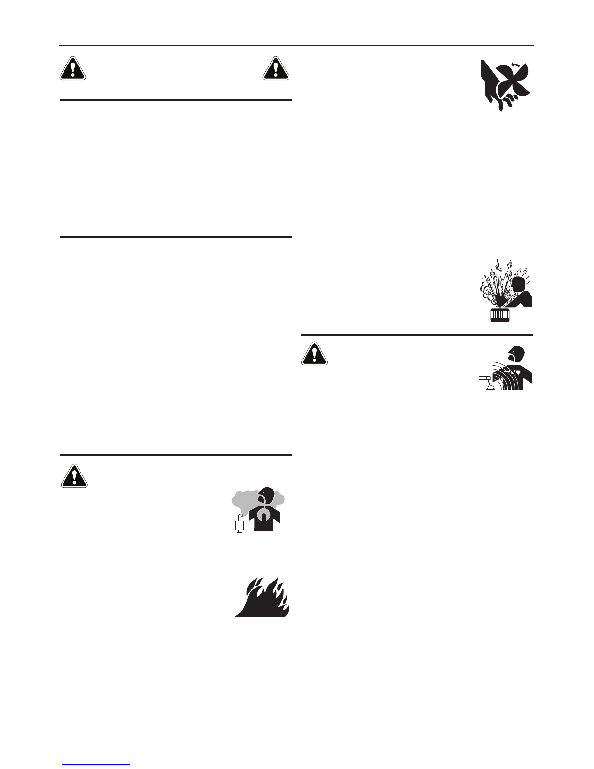
FOR ENGINE POWERED
EQUIPMENT.
1.a. Turn the engine off before troubleshooting
and maintenance work unless the
maintenance work requires it to be running.
1.b. Operate engines in open, well-ventilated
areas or vent the engine exhaust fumes outdoors.
1.c. Do not add the fuel near an open flame
welding arc or when the engine is running.
Stop the engine and allow it to cool before
refueling to prevent spilled fuel from
vaporizing on contact with hot engine parts
and igniting. Do not spill fuel when filling
tank. If fuel is spilled, wipe it up and do not start engine until
fumes have been eliminated.
1.d. Keep all equipment safety guards, covers and
devices in position and in good repair.Keep
h
ands, hair, clothing and tools away from
V-belts, gears, fans and all other moving parts
when starting, operating or repairing
equipment.
1.e. In some cases it may be necessary to remove safety guards to
perform required maintenance. Remove guards only when
n
ecessary and replace them when the maintenance requiring
their removal is complete. Always use the greatest care when
working near moving parts.
1.f. Do not put your hands near the engine fan. Do not attempt to
override the governor or idler by pushing on the throttle control
rods while the engine is running.
1.g. To prevent accidentally starting gasoline engines while turning
the engine or welding generator during maintenance work,
disconnect the spark plug wires, distributor cap or magneto wire
as appropriate.
1.h. To avoid scalding, do not remove the radiator
pressure cap when the engine is
hot.
ELECTRIC AND
MAGNETIC FIELDS MAY
BE DANGEROUS
2.a. Electric current flowing through any conductor
causes localized Electric and Magnetic Fields (EMF). Welding
current creates EMF fields around welding cables and welding
machines
2.b. EMF fields may interfere with some pacemakers, and welders
having a pacemaker should consult their physician before
welding.
2.c. Exposure to EMF fields in welding may have other health effects
which are now not known.
2.d. All welders should use the following procedures in order to
minimize exposure to EMF fields from the welding circuit:
2.d.1. Route the electrode and work cables together - Secure
them with tape when possible.
2.d.2. Never coil the electrode lead around your body.
2.d.3. Do not place your body between the electrode and work
cables. If the electrode cable is on your right side, the
work cable should also be on your right side.
2.d.4. Connect the work cable to the workpiece as close as possible to the area being welded.
2.d.5. Do not work next to welding power source.
3
SAFETY
Page 4
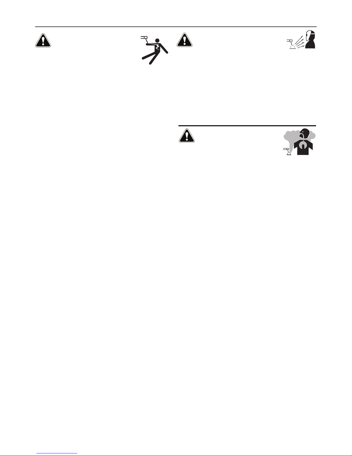
ELECTRIC SHOCK
CAN KILL.
3.a. The electrode and work (or ground) circuits are
e
lectrically “hot” when the welder is on. Do
not touch these “hot” parts with your bare skin
or wet clothing. Wear dry, hole-free gloves to insulate hands.
3.b. Insulate yourself from work and ground using dry insulation.
Make certain the insulation is large enough to cover your full area
of physical contact with work and ground.
0$'',6,10616+(014/$.5$)(6;24(&$76,105,)
9(.',0*/756%(2(4)14/('70'(4(.(&64,&$..;
+$<$4'175&10',6,105,0'$/2.1&$6,105149+,.(
9($4,0*9(6&.16+,0*10/(6$.5647&674(557&+$5
).1145*4$6,0*5145&$))1.'59+(0,0&4$/2('
215,6,10557&+$55,66,0*-0((.,0*14.;,0*,)6+(4(
,5$+,*+4,5-1)70$81,'$%.(14$&&,'(06$.&106$&6
9,6+6+(914-2,(&(14*4170'75(6+()1..19,0*
(37,2/(06
• Semiautomatic DC Constant Voltage (Wire) Welder.
• DC Manual (Stick) Welder.
• AC Welder with Reduced Voltage Control.
3.c. In semiautomatic or automatic wire welding, the electrode,
electrode reel, welding head, nozzle or semiautomatic welding
gun are also electrically “hot”.
3.d. Always be sure the work cable makes a good electrical
connection with the metal being welded. The connection should
be as close as possible to the area being welded.
3.e. Ground the work or metal to be welded to a good electrical (earth)
ground.
3.f. Maintain the electrode holder, work clamp, welding cable and
welding machine in good, safe operating condition. Replace
damaged insulation.
3.g. Never dip the electrode in water for cooling.
3.h. Never simultaneously touch electrically “hot” parts of electrode
holders connected to two welders because voltage
between the
two can be the total of the open circuit voltage of both
welders.
3.i. When working above floor level, use a safety belt to protect
yourself from a fall should you get a shock.
3.j. Also see It ems 6.c. and 8.
ARC RAYS CAN BURN.
4.a. Use a shield with the proper filter and cover plates to protect your
e
yes from sparks and the rays of the arc when welding or
observing open arc welding. Headshield and filter lens should
conform to ANSI Z87. I standards.
4.b. Use suitable clothing made from durable flame-resistant material
to protect your skin and that of your helpers from the arc rays.
4.c. Protect other nearby personnel with suitable, non-flammable
screening and/or warn them not to watch the arc nor expose
themselves to the arc rays or to hot spatter or metal.
FUMES AND GASES
CAN BE DANGEROUS.
5.a. Welding may produce fumes and gases
hazardous to health. Avoid breathing these
fumes and gases. When welding, keep your head out of the fume.
Use enough ventilation and/or exhaust at the arc to keep fumes
and gases away from the breathing zone. +(09(.',0*
9,6+(.(&641'(59+,&+4(37,4(52(&,$.8(06,.$6,10
57&+$556$,0.(5514+$4')$&,0*5((,05647&6,105
10&106$,0(4141410.($'14&$'/,7/
2.$6('56((.$0'16+(4/(6$.514&1$6,0*59+,&+
241'7&(+,*+.;61:,&)7/(5-((2(:21574($5.19
$52155,%.($0'9,6+,0$22.,&$%.($0'
.,/,6575,0*.1&$.(:+$75614
/(&+$0,&$.8(06,.$6,100&10),0('52$&(514,0
51/(&,4&7/56$0&(5176'1145$4(52,4$614/$;
%(4(37,4(''',6,10$.24(&$76,105$4($.51
4(37,4('9+(09(.',0*10*$.8$0,<('56((.
5. b. The operation of welding fume control equipment is affected by
various factors including proper use and positioning of the
equipment, maintenance of the equipment and the specific
welding procedure and application involved. Worker exposure
level should be checked upon installation and periodically
thereafter to be certain it is within applicable OSHA PEL and
ACGIH TLV limits.
5.c. Do not weld in locations near chlorinated hydrocarbon vapors
coming from degreasing, cleaning or spraying operations. The
heat and rays of the arc can react with solvent vapors to form
phosgene, a highly toxic gas, and other irritating products.
5.d. Shielding gases used for arc welding can displace air and
cause
injury or death. Always use enough ventilation, especially in
confined areas, to insure breathing air is safe.
5.e. Read and understand the manufacturer’s instructions for this
equipment and the consumables to be used, including the
material safety data sheet (MSDS) and follow your employer’s
safety practices. MSDS forms are available from your welding
distributor or from the manufacturer.
5.f. Also see item 1.b.
4
SAFETY
Page 5
WELDING AND CUTTING
SPARKS CAN CAUSE
FIRE OR EXPLOSION.
6.a. Remove fire hazards from the welding area. If
this is not possible, cover them to prevent the
welding sparks from starting a fire. Remember that welding
s
parks and hot materials from welding can easily go through
small cracks and openings to adjacent areas. Avoid welding near
hydraulic lines. Have a fire extinguisher readily available.
6.b. Where compressed gases are to be used at the job site, special
precautions should be used to prevent hazardous situations.
Refer to “Safety in Welding and Cutting” (ANSI Standard Z49.1)
and the operating information for the equipment being used.
6.c. When not welding, make certain no part of the electrode circuit is
touching the work or ground. Accidental contact can cause
overheating and create a fire hazard.
6.d. Do not heat, cut or weld tanks, drums or containers until the
proper steps have been taken to insure that such procedures will
not cause flammable or toxic vapors from substances inside.
They can cause an explosion even though they have been
“cleaned”. For information, purchase “Recommended Safe
Practices for the Preparation for Welding and Cutting of
Containers and Piping That Have Held Hazardous Substances”,
AWS F4.1 from the American Welding Society (see address
above).
6.e. Vent hollow castings or containers before heating, cutting or
welding. They may explode.
6.f. Sparks and spatter are thrown from the welding arc. Wear oil free
protective garments such as leather gloves, heavy shirt, cuffless
trousers, high shoes and a cap over your hair. Wear ear plugs
when welding out of position or in confined places. Always wear
safety glasses with side shields when in a welding area.
6.g. Connect the work cable to the work as close to the welding area
as practical. Work cables connected to the building framework or
other locations away from the welding area increase the
possibility of the welding current passing through lifting chains,
crane cables or other alternate circuits. This can create fire
hazards or overheat lifting chains or cables until they fail.
6.h. Also see item 1.c.
6.I. Read and follow NFPA 51B “ Standard for Fire Prevention During
Welding, Cutting and Other Hot Work”, available from NFPA, 1
Batterymarch Park, PO box 9101, Quincy, Ma 022690-9101.
6.j. Do not use a welding power source for pipe thawing.
CYLINDER MAY EXPLODE IF
DAMAGED.
7.a. Use only compressed gas cylinders containing
t
he correct shielding gas for the process used
and properly operating regulators designed for
the gas and pressure used. All hoses, fittings,
etc. should be suitable for the application and
m
aintained in good condition.
7.b. Always keep cylinders in an upright position securely chained to
a
n undercarriage or fixed support.
7.c. Cylinders should be located:
• Away from areas where they may be struck or subjected
to physical damage.
• A safe distance from arc welding or cutting operations
and any other source of heat, sparks, or flame.
7.d. Never allow the electrode, electrode holder or any other
electrically “hot” parts to touch a cylinder.
7.e. Keep your head and face away from the cylinder valve outlet
when opening the cylinder valve.
7.f. Valve protection caps should always be in place and hand tight
except when the cylinder is in use or connected for use.
7.g. Read and follow the instructions on compressed gas cylinders,
associated equipment, and CGA publication P-l, “Precautions for
Safe Handling of Compressed Gases in
Cylinders,” available
from the Compressed Gas Association 1235 Jefferson Davis
Highway, Arlington, VA 22202.
FOR ELECTRICALLY
POWERED EQUIPMENT.
8.a. Turn off input power using the disconnect
switch at the fuse box before working on the
equipment.
8.b. Install equipment in accordance with the U.S. National Electrical
Code, all local codes and the manufacturer’s recommendations.
8.c. Ground the equipment in accordance with the U.S. National
Electrical Code and the manufacturer’s recommendations.
()(461
+662999.,0&1.0(.(&64,&&1/5$)(6;
)14$'',6,10$.5$)(6;,0)14/$6,10
5
SAFETY
Welding Safety
Interactive Web Guide
for mobile devices
Page 6

6
SAFETY
ELECTROMAGNETIC
COMPATIBILITY (EMC)
Products displaying the CE mark are in conformity with European
Community Council Directive of 3 May 1989 on the approximation of
the laws of the Member States relating to electromagnetic compatibility (89/336/EEC). It was manufactured in conformity with a national
s
tandard that implements a harmonized standard: EN 60974-10
Electromagnetic Compatibility (EMC) Product Standard for Arc Welding
Equipment. It is for use with other Lincoln Electric equipment. It is
designed for industrial and professional use.
All electrical equipment generates small amounts of electromagnetic
emission. Electrical emission may be transmitted through power lines
or radiated through space, similar to a radio transmitter. When
emissions are received by other equipment, electrical interference
may result. Electrical emissions may affect many kinds of electrical
equipment; other nearby welding equipment, radio and TV reception,
numerical controlled machines, telephone systems, computers, etc.
Be aware that interference may result and extra precautions may be
required when a welding power source is used in a domestic establishment.
The user is responsible for installing and using the welding equipment
according to the manufacturer’s instructions. If electromagnetic
disturbances are detected then it shall be the responsibility of the
user of the welding equipment to resolve the situation with the
technical assistance of the manufacturer. In some cases this remedial
action may be as simple as earthing (grounding) the welding circuit,
see Note. In other cases it could involve construction of an electromagnetic screen enclosing the power source and the work complete
with associated input filters. In all cases electromagnetic disturbances
must be reduced to the point where they are no longer troublesome.
Note: The welding circuit may or may not be earthed for safety reasons
according to national codes. Changing the earthing arrangements should
only be authorized by a person who is competent to access whether the
changes will increase the risk of injury, e.g., by allowing parallel welding
current return paths which may damage the earth circuits of other equipment.
Before installing welding equipment the user shall make an
assessment of potential electromagnetic problems in the surrounding
area. The following shall be taken into account:
a. other supply cables, control cables, signaling and telephone cables;
above, below and adjacent to the welding equipment;
b. radio and television transmitters and receivers;
c. computer and other control equipment;
d. safety critical equipment, e.g., guarding of industrial equipment;
e. the health of the people around, e.g., the use of pacemakers and
hearing aids;
f. equipment used for calibration or measurement
g. the immunity of other equipment in the environment. The user shall
ensure that other equipment being used in the environment is
compatible. This may require additional protection measures;
h. the time of day that welding or other activities are to be carried out.
T
he size of the surrounding area to be considered will depend on the
structure of the building and other activities that are taking place. The
surrounding area may extend beyond the boundaries of the premises.
Mains Supply
Welding equipment should be connected to the mains supply
a
ccording to the manufacturer’s recommendations. If interference
occurs, it may be necessary to take additional precautions such as
filtering of the mains supply. Consideration should be given to
shielding the supply cable of permanently installed welding
equipment, in metallic conduit or equivalent. Shielding should be
electrically continuous throughout its length. The shielding should be
connected to the welding power source so that good electrical contact
is maintained between the conduit and the welding power source
enclosure.
Maintenance of the Welding Equipment
The welding equipment should be routinely maintained according to
the manufacturer’s recommendations. All access and service doors
and covers should be closed and properly fastened when the welding
equipment is in operation. The welding equipment should not be
modified in any way except for those changes and adjustments
covered in the manufacturers instructio ns. In particular, the spark
gaps of arc striking and stabilizing devices should be adjusted and
maintained according to the manufacturer’s recommendations.
Welding Cables
The welding cables should be kept as short as possible and should be
positioned close together, running at or close to floor level.
Equipotential Bonding
Bonding of all metallic components in the welding installation and
adjacent to it should be considered. However, metallic components
bonded to the work piece will increase the risk that the operator could
receive a shock by touching these metallic components and the
electrode at the same time. The operator should be insulated from all
such bonded metallic components.
Earthing of the Workpiece
Where the workpiece is not bonded to earth for electrical safety, not
connected to earth because of its size and position, e.g., ships hull or
building steelwork, a connection bonding the workpiece to earth may
reduce emissions in some, but not all instances. Care should be taken
to prevent the earthing of the work piece increasing the risk of injury
to users, or damage to other electrical equipment. Where necessary,
the connection of the workpiece to earth should be made by a direct
connection to the work piece, but in some countries where direct
connection is not permitted, the bonding should be achieved by
suitable capacitance, selected according to national regulations.
Screening and Shielding
Selective screening and shielding of other cables and equipment in
the surrounding area may alleviate problems of interference.
Screening of the entire welding installation may be considered for
special applications.
1
Portions of the preceding text are contained in EN 60974-10: “Electromagnetic
Compatibility (EMC) product standard for arc welding equipment.”
Page 7

7
TABLE OF CONTENTS
V
205-T DC & V205-T AC/DC
Page
General Description ................................................................................................................................................8
I
nstallation ................................................................................................................................................Section A
Technical Specifications................................................................................................................................A-1
Select Suitable Location................................................................................................................................A-2
Stacking .......................................................................................................................................................A-2
T
ilting ...........................................................................................................................................................A-2
Environmental Area.......................................................................................................................................A-2
Machine Grounding and High Frequency Interference Protection ...................................................................A-2
Input Connections .........................................................................................................................................A-3
Reconnect Procedure....................................................................................................................................A-3
230V Input............................................................................................................................................A-4
115V Input............................................................................................................................................A-4
Attachment Plug Installation, Engine Driven Generator ..........................................................................A-4
Output Connections.......................................................................................................................................A-5
Output and Gas Connection for Tig Welding...................................................................................................A-5
Work Cable Connection .................................................................................................................................A-5
Output Connection for Stick Welding .............................................................................................................A-5
Quick Disconnect Plug..........................................................................................................................A-6
Shielding Gas Connection .....................................................................................................................A-6
Remote Control Connection...................................................................................................................A-6
_________________________________________________________________________________________
Operation Section B
Safety Instructions ........................................................................................................................................B-1
Welding Capability ........................................................................................................................................B-1
Limitations....................................................................................................................................................B-1
Rear Control Panel ........................................................................................................................................B-1
Controls and Settings, 2 Step and 4 Step Tig Sequence..........................................................................B-2,B-4
Welding Parameter Defaults and Ranges.......................................................................................................B-4
Set Up Menu.................................................................................................................................................B-5
Output Limitations ........................................................................................................................................B-6
DC Tig Welding ............................................................................................................................................B-6
Welding Polarity............................................................................................................................................B-6
DC Electrode Negative Polarity..............................................................................................................B-6
DC Electrode Positive Polarity ...............................................................................................................B-7
D.C.-Pulsed TIG ....................................................................................................................................B-7
A.C. (Alternating Current) ......................................................................................................................B-7
A.C.-Pulsed TIG (Alternating Current Pulsed) .........................................................................................B-7
Steel Tig Welding..........................................................................................................................................B-8
Copper Tig Welding.......................................................................................................................................B-8
Tips For AC TIG Welding................................................................................................................................B-8
GTAW Process ..............................................................................................................................................B-8
Protective Gas, Tips For Improved TIG Starting..............................................................................................B-9
AC Tig Welding Quick Start Up ....................................................................................................................B-10
DC Tig Welding Quick Start Up ....................................................................................................................B-11
_________________________________________________________________________________________
Accessories .............................................................................................................................Section C
Optional Accessories and Compatible Equipment .........................................................................C-1
Factory, Field Installed .................................................................................................................C-1
________________________________________________________________________________
Maintenance............................................................................................................................Section D
Safety Precautions.......................................................................................................................D-1
Input Filter Capacitor Discharge Procedure ..................................................................................D-1
Routine Maintenance ...................................................................................................................D-1
________________________________________________________________________________
Troubleshooting.......................................................................................................................Section E
How to Use Troubleshooting Guide...............................................................................................E-1
Troubleshooting Guide....................................................................................................E-2 thru E-4
________________________________________________________________________________
Wiring Diagram........................................................................................................................Section F
________________________________________________________________________________
Parts Lists......................................................................................................................................P-560
Page 8

8
GENERAL DESCRIPTION
V
205-T DC & V205-T AC/DC
GENERAL DESCRIPTION
GENERAL DESCRIPTION
The Invertec V205-T DC & V205-T AC/DC are industrial 200 amp
arc welding power sources that utilize single phase input power,
to produce constant current output. The welding response has
b
een optimized for stick (SMAW) and TIG (GTAW). The units are
ideal for industrial applications where portability is important.
The Invertec V205-T AC/DC is a power source that can perform
the following types of welding with excellent results:
• TIG AC with square, sinusoidal and triangular waveforms.
• TIG DC (with high frequency or Touch Start TIG Starting)
• Stick DC
The Invertec V205-T DC is a power source that can perform the
following types of welding with excellent results:
• TIG DC (with high frequency or Touch Start TIG Starting)
• Stick DC
The following items can be connected to the 6 pin socket on the
front panel:
• Remote control potentiometer for Stick welding.
•
Remote Foot Amptrol or Hand Amptrol
• Arc Start Switch
NOTE: See Accessories section of this manual for product numbers and complete description.
Page 9
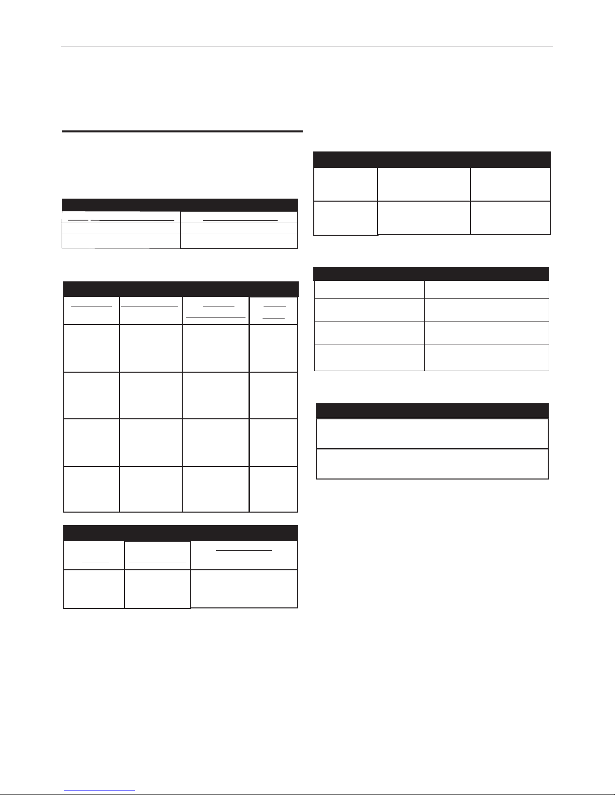
Input
Amps
34A
28A
20A
34A
25A
20A
30A
23A
19A
30A
18A
15A
Output Amps Volts at
Rated Amperes
(Stick) 110 24.4V
90 23.6V
70 22.8V
(TIG) 150 16V
120 14.8V
100 14V
(Stick) 180 27.2V
150 26V
130 25.2V
(TIG) 200 18V
170 16V
140 15.6V
Duty Cycle
(115V) 35%
60%
100%
(115V) 40%
60%
100%
(230V) 35%
60%
100%
(230V) 40%
60%
100%
Output Current
Range
6-200 Amps
Maximum Open
Circuit Voltage
54 Volts Max.
Type of Output
DC (K2629-1)
AC/DC (K1855-4)
A-1
INSTALLATION
V
205-T DC & V205-T AC/DC
TECHNICAL
SPECIFICATIONS
INPUT - SINGLE PHASE ONLY
RATED OUTPUT
OUTPUT
PHYSICAL DIMENSIONS
* Note: Refer to RECONNECT PROCEDURE (Table A.1) for
Input Voltage Operating Range.
RECOMMENDED INPUT WIRE AND FUSE SIZES
(1)
In
p
u
t
V
ol
t
a
g
e
s
*
/50
/60
H
z
.
115
230
Max. Input Current
34A at Rated Output
30A at Rated Output
Height
Width
Depth
Weight
15 in. (381 mm)
8.5 in. (216mm)
19 in. (483mm)
38 lbs. (17kg)
I
NPUT VOLTAGE /
FREQUENCY (HZ)
115/50/60
230/50/60
T
YPE
S,
SO
ST
,
ST
O
,
O
R
E
X
T
R
A
H
A
R
D
U
SA
G
E
I
N
PU
T
C
O
R
D
A
W
G
#
1
2
TIME-DELAY CIRCUIT
BREAKER OR FUSE
SIZE (AMPS)
30 A
(1) Maximum Rated Output
TEMPERATURE RANGES
OPERATING TEMPERATURE RANGE
-20°C to +40°C
STORAGE TEMPERATURE RANGE
-50°C to +85°C
V205-T DC
K2629-1 (Code Number 11426)
V205-T AC/DC
K1855-4 (Code Number 11430)
Page 10

A-2
INSTALLATION
V
205-T DC & V205-T AC/DC
Read entire installation section before starting
installation.
SAFETY PRECAUTIONS
ELECTRIC SHOCK can kill.
• Only qualified personnel should perform
this installation.
• Turn the input power OFF and unplug the
machine from the receptacle before working on this equipment. Allow machine to sit
for 5 minutes
minimum to allow the power
capacitors to discharge before working
inside this equipment.
•
Insulate yourself from the work and ground.
•
Always wear dry insulating gloves.
• Always connect the V205-T to a power supply grounded
according to the National Electrical Code and local codes.
-------------------------------------------------------
SELECT SUITABLE LOCATION
The Invertec will operate in harsh environments. Even so, it is
important that simple preventative measures are followed in order
to assure long life and reliable operation.
• The machine must be located where there is free circulation of
clean air such that air movement in the back and out the front
will not be restricted.
• Dirt and dust that can be drawn into the machine should be kept
to a minimum. Failure to observe these precautions can result in
excessive operating temperatures and nuisance shutdown.
STACKING
The Invertec V205-T DC & V205-T AC/DC can not be stacked.
TILTING
Place the machine directly on a secure, level surface. The
machine may topple over if this procedure is not followed.
ENVIRONMENTAL AREA
Keep the machine dry. Do not place it on wet ground or in puddles.
MACHINE GROUNDING AND HIGH FREQUENCY
INTERFERENCE PROTECTION
The Capacitor Discharge Circuit used in the high frequency generator, may cause many radio, TV and electronic equipment interference problems. These problems may be the result of radiated
i
nterference. Proper grounding methods can reduce or eliminate
radiated interference.
The Invertec V205-T DC & V205-T AC/DC have been field tested
under recommended installation conditions. It complies with FCC
allowable limits for radiation.
Radiated interference can develop in the following four ways:
1. Direct interference radiated from the welder.
2. Direct interference radiated from the welding leads.
3. Direct interference radiated from feedback into the power
lines.
4. Interference from re-radiation of “pickup” by
ungrounded metallic objects.
Keeping these contributing factors in mind, installing equipment
per the following instructions should minimize problems.
1. Keep the welder power supply lines as short as possible and
enclose as much of them as possible in rigid metallic conduit
or equivalent shielding for a distance of 50 feet (15.2m). There
should be good electrical contact between this conduit and the
welder case ground. Both ends of the conduit should be connected to a driven ground and the entire length should be continuous.
2. Keep the work and electrode leads as short as possible and as
close together as possible. Lengths should not exceed 25 ft
(7.6m).
WARNING
Page 11

A-3
INSTALLATION
V
205-T DC & V205-T AC/DC
3. Be sure the torch and work cable rubber coverings are free of
cuts and cracks that allow high frequency leakage. Cables
with high natural rubber content, such as Lincoln Stable-Arc
®
b
etter resist high frequency leakage than neoprene and other
synthetic rubber insulated cables.
4. Keep the torch in good repair and all connections tight to
reduce high frequency leakage.
5. The work terminal must be connected to a ground within ten
feet of the welder, using one of the following methods.
a) A metal underground water pipe in direct contact with
the earth for ten feet or more.
b) A 3/4” (19mm) galvanized pipe or a 5/8” (16mm) solid
galvanized iron, steel or copper rod driven at least eight
feet into the ground.
The ground should be securely made and the grounding
cable should be as short as possible using cable of the same
size as the work cable, or larger. Grounding to the building
frame electrical conduit or a long pipe system can result in
re-radiation, effectively making these members radiating
antennas.
6. Keep all panels securely in place.
7. All electrical conductors within 50 ft (15.2m) of the welder
should be enclosed in grounded, rigid metallic conduit or
equivalent shielding. Flexible metallic conduit is generally not
suitable.
8. When the welder is enclosed in a metal building, several
earth driven electrical grounds connected (as in 5b above)
around the periphery of the building are recommended.
Failure to observe these recommended installation procedures can
cause radio or TV interference problems.
INPUT CONNECTIONS
Be sure the voltage, phase, and frequency of the input
power is as specified on the rating plate, located on the bottom of
the machine.
ELECTRIC SHOCK can kill.
• Have a qualified electrician install and
service this equipment.
• Turn the input power OFF and unplug
the machine from the receptacle
before working on this equipment.
• Allow machine to sit for 5 minutes
minimum to allow the
power capacitors to discharge before working inside this
equipment.
• Do not touch electrically hot parts.
• Machine must be plugged into a receptacle that is grounded according to the National Electrical Code and local
codes.
• Do not remove or defeat the purpose of the power cord
ground pin.
------------------------------------------------------------------
RECONNECT PROCEDURE
The Invertec V205-T DC & V205-T AC/DC auto reconnect to either
115V or 230V supply.
This machine is capable of operating within the following input
voltage ranges (Table A.1):
TABLE A.1
Fuse the input circuit with time delay fuses or delay type¹circuit
breakers. Using fuses or circuit breakers smaller than recommended may result in “nuisance” shut-offs from welder inrush
currents even if not welding at high currents.
The Invertec Power Source is recommended for use on an individual branch circuit.
¹
Also called “inverse time” or “thermal/magnetic” circuit breakers. These circuit
breakers have a delay in tripping action that decreases as the magnitude of the
current increases.
WARNING
NOMINAL
115V
208V / 230V
RANGE
90-140V
184-276V
Page 12

A-4
INSTALLATION
V
205-T DC & V205-T AC/DC
230V INPUT
The equipment is provided with a 230/115V cable, 6.6ft.(2m) in
l
ength with a 230V 6-50P attachment plug.
The Invertec V205-T performs best when connected to 230VAC
inputs. This input allows full output of the machine (200 amps).
115V INPUT
A suitable 115V attachment plug must be installed on the power cord
to use the V205-T with a 115V input supply. The rated output of the
V205-T is available when connected to a 30A branch circuit. When
connected to a branch circuit with lower amp rating, lower welding
current and duty cycle must be used. An output guide is provided
below. The values are approximate and must be adjusted downward
if the fuse or circuit breaker trips off. Other loads on the circuit and
fuse/circuit breaker characteristics will affect the available output. Do
not exceed these welding conditions:
15A branch circuit
10% duty cycle
Stick: 75A
TIG: 105A
20A branch circuit
10% duty cycle
Stick: 90A
TIG: 130A
ATTACHMENT PLUG INSTALLATION
Connect the white (neutral) wire under terminal clamp with silver
screw, and black (hot) wire under terminal clamp with brass
screw. Connect green wire under terminal clamp with green
screw.
•
Failure to wire as instructed may cause personal injury or
damage to equipment. To be installed or checked by an
electrician or qualified person only.
------------------------------------------------------------------
In all cases, the green or green/yellow grounding wire must be connected to the grounding pin of the plug, usually identified by a green
screw.
Attachment plugs must comply with the Standard for Attachment
Plugs and Receptacles, UL498.
The product is considered acceptable for use only when an attachment plug as specified is properly attached to the supply cord.
For use on engine drives, keep in mind the above input draw
restrictions and the following precaution.
ENGINE DRIVEN GENERATOR
The Invertec V205-T DC & V205-T AC/DC can be operated on
engine driven generators as long as the 230 volt auxiliary meets
the following conditions:
• The AC waveform peak voltage is below 400 volts.
• The AC waveform frequency is between 45 and 65Hz.
The following Lincoln engine drives meet these condi-tions when
run in the high idle mode:
• Ranger 250, 250 LPG, 305 G, 305 D
*
• Vantage 300, 400, 500 & Air Vantage 500
*
Some engine drives do not meet these conditions (e.g. Miller
Bobcats, etc). Operation of the Invertec V205-T AC/DC is not recommended on engine drives not conforming to these conditions.
Such drives may deliver unacceptably high voltage levels to the
Invertec power source.
*
Ranger and Vantage Engine Drives require the full KVA Adapter
Kit (K1816-1)
WARNING
Page 13

A-5
INSTALLATION
V
205-T DC & V205-T AC/DC
OUTPUT CONNECTIONS
ELECTRIC SHOCK can kill.
• Keep the electrode holder, TIG torch and
cable insulation in good condition and in
place.
• Do not touch electrically live parts or elect
rode with skin or wet clothing.
• Insulate yourself from work and ground.
• Turn the input line Switch on the Invertec V205-T DC & V205T AC/DC “off” before connecting or disconnecting output
cables or other equipment.
-----------------------------------------------------------------
OUTPUT AND GAS CONNECTION FOR TIG WELDING
(FIGURE A.1)
The TIG Torch Twist-Mate and work cable Twist-Mate Connectors
are supplied with the welder. To connect the cables,turnthe Power
Switch“OFF”.
Connect the torch cable Twist-Mate plug into the DC(-)
Electrode/Gas Output Receptacle on the front of the welder and
turn it clockwise until snug,(Do not Overtighten). This is a quick
connect terminal and also provides the gas connection for the
shielding gas to the torch.
To avoid receiving a high frequency shock, keep the TIG torch
and cable Insulation in good condition.
_________________________________________________
WORK CABLE CONNECTION
Next, connect the work cable to the “+” output terminal in the
same way.
To minimize high frequency interference, refer to Machine
Grounding and High Frequency Interference Protection section
of this manual for the proper procedure on grounding the work
clamp and work piece.
This unit does not include a TIG torch, but one may be purchased
separately. The accessories section of this manual lists a number
of Lincoln Electric TIG torches, and TIG Torch Starter Packs that
are recommended for use with this machine; however, any similar
TIG torch can be used. To attach the Twist-Mate Plug to a Lincoln
Torch, slide the rubber boot onto the torch cable (enlarge the boot
opening if necessary), screw the fitting on the torch cable into the
brass connector snugly and slide the boot back over the brass
connector.
OUTPUT CONNECTION FOR STICK WELDING (FIGURE
A.2)
First determine the proper electrode polarity for the electrode to
be used. Consult the electrode data for this information. Then
connect the output cables to the output terminals corresponding to
this polarity. For instance, for DC(+) welding, connect the electrode cable (which is connected to the electrode holder) to the “+”
output terminal and the work cable (which is connected to the
work clamp) to the “-” output terminal. Insert the connector with
the key lining up with the keyway, and rotate clockwise; until the
connection is snug. Do not over tighten.
WARNING
+
-
WORK CLAMP
WORK CABLE
TIG TORCH
FIGURE A.1
TIG ADAPTER
R
ETAINING COMPOUND
STRAIN RELIEF BOOT
T
IG TORCH POWER CABLE WITH GAS FITING
+
-
FIGURE A.2
WORK CABLE
WORK CABLE
STICK ELECTRODE
HOLDER
Page 14

A-6
INSTALLATION
V
205-T DC & V205-T AC/DC
QUICK DISCONNECT PLUG (FOR STICK ELECTRODE CABLE and
WORK CABLE)
A quick disconnect system is used for the welding cable connections. The stick electrode cable will need to have a plug attached.
1. Cut off welding cable lug, if present.
2. Remove 1.00 in. (25mm) of welding cable insulation.
3. Slide rubber boot onto cable end. The boot end may be
trimmed to match the cable diameter. Use soap or other nonpetroleum-based lubricant to help slide the boot over the
cable, if needed.
4. Insert copper strands into ferrule.
5. Slide the copper ferrule into the brass plug.
6. Tighten set screw to collapse copper tube. Screw must apply
pressure against welding cable. The top of the set screw will
be well below the surface of the brass plug after tightening.
7. Slide rubber boot over brass plug. The rubber boot must be
positioned to completely cover all electrical surfaces after the
plug is locked into the receptacle.
SHIELDING GAS CONNECTION
Obtain the necessary inert shielding gas. Connect the cylinder of
gas with a pressure regulator and flow gage. Install a gas hose
b
etween the regulator and gas inlet (located on the rear of the
welder). The gas inlet has a 5/16-18 right hand female thread;
CGA #032.
CYLINDER could explode
if damaged.
• Keep cylinder upright and chained to a
support.
• Keep cylinder away from areas where it could be
damaged.
• Never allow the torch or welding electrode to touch
the cylinder.
• Keep cylinder away from live electrical circuits.
------------------------------------------------------------------
REMOTE CONTROL CONNECTION
A remote control receptacle is provided on the lower center case
front of the welder for connecting a remote control to the machine.
Refer to the Optional Accessories section of this manual for available remote controls.
25 mm
1.00 in.
WELDING CABLE
BOOT
TRIM, IF REQ'D
TO FIT OVER CABLE
WELDING CABLE
COPPER FERRULE
SET SCREW
BRASS PLUG
COPPER TUBE
WARNING
Page 15

B-1
OPERATION
V
205-T DC & V205-T AC/DC
Read and understand this entire section before operating
your machine.
SAFETY INSTRUCTIONS
ELECTRIC SHOCK can kill.
• Do not touch electrically live parts such as
output terminals, electrode or internal wiring.
• Insulate yourself from the work and ground.
• Always wear dry insulating gloves.
------------------------------------------------------------------
FUMES AND GASES
can be dangerous.
• Keep your head out of fumes.
• Use ventilation or exhaust to
remove fumes from breathing
zone.
------------------------------------------------------------------
WELDING, CUTTING and
GOUGING SPARKS
can cause fire or explosion
•Keep flammable material away.
•Do not weld, cut or gouge on
containers that have held combustibles.
------------------------------------------------------------------
ARC RAYS
can burn.
• Wear eye, ear and body
protection.
------------------------------------------------------------------
Only qualified personnel should operate this equipment.
Observe all safety information throughout this manual.
WELDING CAPABILITY
T
he Invertec V205-T DC & V205-T AC/DC is rated at 200 amps, 18
volts, at 40% duty cycle on a ten minute basis. It is capable of
higher duty cycles at lower output currents. It is capable of 140
amps, 15.6 volts at at 100% duty cycle. If the duty cycle is
e
xceeded, a thermal protector will shut off the output until the
machine cools. See Technical Specifications in A-1 for other rated
outputs.
The Invertec V205-T is recommended for stick welding with such
popular electrodes as Fleetweld 5P and 5P+ (E6010), Fleetweld
35 (E6011), Fleetweld 37 (E6013), Fleetweld 180 (E6011) and
Excalibur 7018.
LIMITATIONS
The V205-T is not recommended for pipe thawing.
REAR CONTROL PANEL (FIGURE B.1)
• I1: Off/On switch turns on the electric power to the welder.
It has two positions, "O" off, and "I" on.
------------------------------------------------------------------
* With "l1" in the "I" (ON) position, the welding machine is opera-
tional and there is voltage between the positive (+) and negative
(-) Terminals in stick welding. In TIG, the welding process needs
a trigger closure command at the remote control
connection.(Usually via an Arc Start Switch or Foot Amptrol)
* The welder is connected to the supply even if the “l1” (Power
Switch) is in the "O" (Off) position, and therefore there are electrically live parts inside the power source. Carefully follow the
instructions given in this manual.
FIGURE B.1
* 1 : Supply cable
* 2 : Gas attachment
l1 : Power Switch
WARNING
Page 16

B-2
OPERATION
CONTROLS AND SETTINGS
All operator controls and adjustments are located on the case front
of the V205-T machine. Refer to Figure B.2 and the corresponding
explanations.
1. Input Voltage warning light green LED - Indicates that the
machine is on and input voltage is within acceptable range.
2
. Thermal Shutdown Light (yellow LED) - Indicates thermal
over load or output disabled for incorrect supply voltage.
• With the "Yellow LED" on, and an alarm code blinking on
"Digital Display Item 6" (see Troubleshooting Section E,
"Possible electrical problems"), the machine will not supply
power at the output.
• If over-heating occurs, the "Yellow LED" will stay on until the
machine has sufficiently cooled. Leave the power source on to
allow the fan to cool the unit.
3. Pulse On/OFF push button - CONSTANT current - PULSED
current
4. Setup/Parameter Select push button -“Setup/Parameter"
push button has three (3) different functions:
•
Access Welding Parameter. Repeatedly pressing the Parameter
button will step through the Welding Parameter waveform lights on
the front panel. Parameters which can be changed.
Start Current
Upslope
Weld Current (Peak Current)
Pulse Frequency
% on Time
Background Current
Downslope
Finish Current
Postflow sec.
There is a LED for each welding parameter. When lit, it has confirmed the mode or selection chosen.
•
Access the "AC Frequency" and "AC Balance" by pressing and
holding the Parameter button for three (3) seconds. (AC/DC model
only)
•
Access the "Set Up Menu". See Set Up Menu section.
5. Output / Parameter Adjust Knob - Allows you to continuously
adjust the current both in TIG and in Stick welding. Allows you to
change the value, shown on "Digital Display Item 6", of the parameter selected with "Setup/Parameter select button Item 4".
V
205-T DC & V205-T AC/DC
2. Thermal / Device Warning Light Yellow LED
6. Digital Display
1. Input Voltage warning Light Green LED
5
. Output/Parameter Adjust Knob
4. Setup/Parameter Select Button
9. Welding Process (MODE) Button
7. Local/Remote Button
3
. Pulse On/Off Button
8.Trigger Selection Button
10. Electrode Connection (Negative)
11. Remote Control Connector
12. Electrode Connection (Positive)
13. Welding Parameter Drawing
14. VRD (Voltage Reduction Device) Status Light
sec
sec
LOCAL
1
9
10
11
12
1
3
8
7
6
5
4
3
2
VDR OFF
VDR ON
1
4
FIGURE B.2
Page 17

B-3
OPERATION
6. Digital Display - displays currently set values for each mode
or welding parameter.
7
. Local/Remote push button - Selects the welding current
adjusting system:
• from front panel
• from remote control
The LED beside the symbol confirms the selection.
8. Tig Trigger Sequences - For the V205-T AC/DC, TIG welding
can be done in either the 2-step or 4-step mode which is
selected with the Trigger Mode Push Button.
2-Step Sequence
With the Trigger Mode switch in the 2-step position, the following welding sequence will occur. This sequence is shown in (2-
step diagram 1)
1. Press and hold the Arc Start Switch to start the sequence.
The machine will open the gas valve to start the flow of the
shielding gas. After a 0.5 second preflow time, to purge air from
the torch hose, the output of the machine is turned ON. At this
time the arc is started.
After the arc is started the output current will be increased from
the start current to the welding current. Both the start current
and increase, or upslope time are presettable. The default start
current is 15 amps and the default upslope time is 0.2 seconds.
2. Release the Arc Start Switch to stop welding.
The machine will now decrease the output current at a controlled rate, or downslope time, until the Finish current, (also
commonly referred to as Crater Current) is reached and the output of the machine is turned OFF. Both the Downslope Time and
the Finish Current are can be preset.
After the arc is turned OFF, the gas valve will remain open to
continue the flow of the shielding gas to the hot electrode and
work piece. The duration of this postflow shielding gas is adjusted by the Postflow Parameter.
Possible variations of this standard sequence is shown in (2 step
diagram 2). It is possible to press and hold the TIG torch trigger a
second time during downslope to restart. After the trigger is
pressed the output current will increase to the welding current.
This operation is shown in (2 step diagram 2).
4-Step Sequence
With the 4-step Selected, the following welding sequence will
occur.
1. Press and hold the Arc Start Switch to start the sequence.
The machine will open the gas valve to start the flow of the
shielding gas. After a 0.5 second preflow time, to purge air from
the torch hose, the output of the machine is turned ON. At this
time the arc is started.
After the arc is started the output current will be at the Start current. This condition can be maintained as long or as short as
necessary.
If the Start current is not necessary, do not hold the TIG torch
trigger as described at the beginning of this step. Instead, quickly press and release the trigger. In this condition, the machine
will automatically pass from Step 1 to Step 2 when the arc is
started.
2. Release the TIG torch trigger to start the main part of the weld.
The output current will be increased from the start current to the
welding current. Both the start current and increase, or upslope
time are presettable. The default start current is 15 amps and
the default upslope time is 0.2 seconds.
3. Press and hold the TIG torch trigger when the main part of the
weld is complete.
The machine will now decrease the output current at a controlled rate, or downslope time, until the Finish current is
reached. Both the Downslope Time and the Finish Current are
presettable. This Finish current can be maintained as long or as
short as necessary.
V
205-T DC & V205-T AC/DC
2 STEP DIAGRAM 1
2 STEP DIAGRAM 2
(1)
(2)
(2)
(2)
(1)
Page 18

B-4
OPERATION
4. Release the TIG torch trigger.
T
he output current of the machine will turn OFF and the gas
valve will remain open to continue the flow of the shielding gas.
The duration of this postflow time is adjusted by the Postflow
parameter. This operation is shown in (4 step diagram 1).
Possible variations of this standard sequence are shown in (4 step
diagram 2). By releasing and re-pressing the TIG torch trigger
during the downslope step, the output will immediately drop to
and hold at the Finish Current. Releasing the trigger will turn off
the output and begin postflow. This operation shown in (4 step
diagram 2)
.
9. Welding selection button - Permits selection of the welding mode. The
LED beside the symbol confirm the selection:
• Stick Crisp-used for E6010 and other cellulosic electrodes
• Stick Soft-used for low Hydrogen and E7018 electrodes
• TIG DC
• TIG AC (AC/DC model only)
10. Electrode Connection (Negative) - For quick disconnect system using
T
wist-Mate
TM
c
able plugs with gas pass through for TIG Torches.
11. Remote Control Connector - For the connection of a Lincoln Foot
Amptrol, Hand Amptrol or Arc Start Switch. See the ACCESSORIES section
f
or available options.
12. Electrode Connection (Positive) - For quick disconnect system using
Twist-Mate
T
M
cable plugs
13. Welding Parameter Display - LED’s show which mode or welding parameter is activated for adjustment.
• If it is necessary to modify the welding parameters "Item 13":
- Wait four seconds after the LED’s on the panel have gone out,
the welding current LED will be lit.
- Press the SETUP/Parameter push button "Item 4"; every time the
push button is pressed, one of the LED’s in the diagram “Item
13” comes on (in clockwise sequence) and the value of the parameter appears on the Digital display "Item 6". Stop at the desired
parameter.
- Rotate the Output/Parameter Adjust Knob"Item 5" and modify the
parameter value.
- Press the SETUP/Parameter "Item 4" push button again to pass
to another parameter, or wait five seconds and the Weld Current
LED will come on again.
14. VRD (Voltage Reduction Device) Status Lights - Voltage reduction
device can be enabled from the set-up menu and an output voltage limit
can be set that reduces the output open circuit voltage when not welding
to that limit. If enabled when the machine is sitting idle the Green VRD on
light will illuminate to indicate the voltage is reduced below the set limit. If
the VRD device is not enabled (factory default) from the set up menu or
while welding the red VRD off light will illuminate.
Note: The green VRD on light will illuminate in TIG mode until the output is
triggered even when VRD is disabled.
V
205-T DC & V205-T AC/DC
WELDING PARAMETER DEFAULTS AND RANGES
PARAMETER VALUE MIN MAX DEFAULT
START CURRENT AMPS 6 MAX 6
UPSLOPE SEC. 0 10 0.2
WELD CURRENT * AMPS 6 MAX 100
DOWNSLOPE SEC. 0 10 1.0
FINISH CURRENT AMPS 6 MAX 8
POSTFLOW SEC. 0.2 60 5.0
PULSE FREQUENCY HZ 0.1 500 0.5
% ON TIME %595 50
BACKGROUND CURRENT
% OF WELD CURRENT
1 100 20
AC FREQUENCY (AC/DC model only)
HZ 20 150 100
AC BALANCE % EN 35 85 75
(AC/DC model only)
(EN = Electrode Negative)
MODE DC TIG
TRIGGER 2 STEP
LOCAL / REMOTE LOCAL
* Maximum Weld Current can be limited by input voltage, Welding Mode, AC TIG waveform and AC TIG frequency.
4 STEP DIAGRAM 1
4 STEP DIAGRAM 2
(1)
(2)
(3)
(3A)
(4)
Page 19

B-5
OPERATION
SET UP MENU
M
any additional parameters can be modified via the
Set Up Menu. To access the Set Up Menu:
• Position the ON/OFF switch to OFF “0”.
•
Depress and hold the Parameter select Push Button.
• Position the On/Off switch to on "I" at the back of the machine;
the input voltage light "Item 1" (green LED) confirms normal
operation.
• The SETUP mode is confirmed by a center "0" on the Digital display “Item 6”.
- Rotate the Output / Parameter Adjust Knob, the Digital Display
shows the numbers corresponding to the parameters in
sequence; stop at the desired parameter and push the
"
Setup/Parameter Push Button".
- The number on the Digital display "Item 6" is replaced by the
value of the parameter that can be modified through the Output /
Parameter adjust knob "Item 5".
- With parameter (11) all the modifications made in the SETUP
mode are cancelled and the standard values set by Invertec
V205-T DC & V205-T AC/DC are restored.
- To exit the Set Up Menu, return to “0” and press the
S
etup/Parameter Push Button
V
205-T DC & V205-T AC/DC
INDICATOR PARAMETER DEFAULT
0 Exit From Set Up
2 Pre Flow Time (0 - 25 seconds) 0.5 sec.
3 Arc Force Soft Mode, Percent above Peak Current for Stick only (0-100%) 30%
4 Hot Start Soft Mode, Percent above Peak Current for Stick only (0-100%) 80%
5 Arc Force Crisp Mode, Pecent above Peak Current for Stick only (0-500%) 350%
6 Hot Start Crisp Mode, Percent above Peak Current for Stick only (0-500%) 150%
Setting the AC Wave Form (AC/DC model only)
0=Sinusoidal
1=Triangular
2=Square
VRD
Off=Disabled
1=Enable (limits OCV to 12V) Off
2=Enable (limits OCV to 20V)
3=Enable (limits OCV to 30V)
Max Current Value with Remote Control
(6 Amps - Peak Current)
NOTE: Peak Current (Max Weld Current) can be limited by input voltage, welding mode, AC TIG waveform and AC TIG frequency.
10 Lift or HF Start in DC, Ignored in AC (0 = HF Start, 1 Touch Start) HF
11 Reset of all Parameters
12 DC TIG STRIKE CURRENT 6-200 40 Amps
13 DC TIG Start Polarity 0=DC- or 1=DC+ 0
2 Step Trigger Selection
14 0 = Restart Disabled 1
1 = Restart Enabled
4 Step Trigger Selection
15 0 = Restart Disabled 0
1 = Restart Enabled
AC TIG Start Power (for AC TIG only on AC/DC model)
This function sets the initial start energy limit. Set this number to a
higher setting than the factory default if needed to improve starting
of large diameter tungsten electrodes.
0.5 to 1.0 manual start energy setting
1.2 to 5.0 = max. Incrementing limit (See Note)
Note: The machine will try to start the machine at a start power of 1.
If the arc does not establish it will incrementally increase the start
power and try to restrike up to the set limit.
TIG PULSED BASE CURRENT Setting:
17 0 = Absolute value setting 1
1 = Percentage value setting
7
8
9
16
2
Peak Current
2 (Square)
Page 20

B-6
OPERATION
OUTPUT LIMITATIONS
The maximum output current as specified in the installation section of this manual is derated in several situations; alternate AC
Wave Forms, elevated AC Frequencies and 115V input.
• Alternate AC Wave Forms (See Set Up Menu)
¹
S
quare 200 amps max. output
Sinusoidal 150 amps max. output
Triangular 120 amps max output
• Elevated AC Frequencies
¹
Above 85Hz (AC output) the square wave output is limited to 170 amps. Elevated AC Frequencies do not effect
the output of Sinusoidal and Triangular Waveforms.
• 115V Operation
150 A TIG Mode
110 A Stick Soft mode
100 A Stick Crisp Mode
These derated values have been programmed into the Invertec
V205-T to ensure reliable operation.
¹
AC/DC model only
DC TIG WELDING
(see FIGURE B.3)
The TIG (Tungsten lnert Gas) welding process is based on the
presence of an electric arc between a non-consumable electrode
(pure or alloyed tungsten with an approximate melting temperature of 3370°C) and the workpiece. An inert gas (typically argon)
atmosphere protects the weld pool.
To avoid inclusions of tungsten in the joint, the electrode should
not contact the workpiece. For this reason the arc is started
through a Hi. Freq. generator.
For situations requiring no Hi. Freq., Touch Start Tig reduces the
short-circuit current to keep tungsten inclusions to the minimum.
To improve weld bead quality at the end of the weld it is important
to carefully control the downslope of current and ensure proper
gas coverage over the weld.
FIGURE B.3
WELDING POLARITY
DC El ectrode Negative Polarity (Direct Current S traight
Polarity)
(see Figure B.4)
While Welding, there is a continuous flow of electrons from the
electrode to the workpiece.
This is the most used polarity, ensuring limited wear of the electrode, since the majority of the heat concentrates on the anode
(workpiece). Narrow and deep welds are obtained with high travel
speeds.
Most materials, with the exception of aluminum and magnesium,
are welded with this polarity.
FIGURE B.4
V
205-T DC & V205-T AC/DC
1) Workpiece 5) Flowmeter
2) Filler material 6) Pressure reducer
3) Non-consumable electrode 7
)
l
nert gas (typically argon)
4) Torch 8)
Power source
Page 21

B-7
OPERATION
DC Electrode Positive Po la rity. (Direct Curre nt Reverse
Polarity) (see Figure B.5)
I
n this case, there is a continuous flow of electrons from the workpiece to the electrode. The reverse polarity is used for welding
alloys covered with a layer of refractory oxide.
With this polarity the electrode functions as anode and is subjected to a high degree of heat; the workpiece is bombarded by positive ions sent from the electrode which break the surface oxide.
In Electrode Positive Polarity, high currents cannot be used, since
they would cause an excessive wear of the electrode.
NOTE: (The Invertec V205-T DC & V205-T AC/DC cannot be used
for Electrode Positive TIG welding without special adapters.)
FIGURE B.5
D.C.- Pulsed TIG
(see Figure B-6)
The use of pulsed direct current allows better control of the weld
pool during certain operating conditions.
When compared with traditional TIG welding performed at the
same average current, pulsed welding results in a smaller heat
affected zone which results in fewer deformations and reduced
chance of cracking and gas entrapment.
Increasing the frequency constricts the arc, increases stability and
improves weld quality.
FIGURE B.6
A.C. (Alternating Current) (AC/DC model only)
(
see Figure B.7)
Alternating Current welding is typically used for Tig welding aluminum (and its alloys) or magnesium. The polarity alternates
between Electrode Positive and Electrode Negative (EN). During
the positive half-wave the oxide is broken. During the negative
h
alf-wave, the electrode cools, the workpiece melts and penetra-
tion occurs.
FIGURE B.7
Changing the wave balance alters the ratio between the cleaning
and the penetrating current.
A.C.- Pulsed TIG
When AC welding, a pulsed current can be used, with similar
effects to those described in pulsed direct current welding.
FIGURE B.8
V
205-T DC & V205-T AC/DC
DC-PULSED TIG
DC TIG- NOT PULSED
Lb
m
Is
T
T
Is
A.C.- PULSED TIG
Greater % EN = MORE PENETRATION
50% (EN)
L
esser % EN = more CLEANING
Page 22

B-8
OPERATION
STEEL TIG WELDING
The TIG process is very effective for welding both carbon steel and
a
lloy steel, especially in applications requiring precision results.
DC Electrode Negative Polarity is required. Since this process does
n
ot include the removal of impurities, proper cleaning and preparation of the edges is required.
FILLER MATERIAL:
T
he filler rods must deposit welds with mechanical characteristics
appropriate for the application.
COPPER TIG WELDING
Since TIG welding is a process characterized by high heat concentration, it is particularly suitable for welding materials with high
thermal conductivity, like copper. As with steel, the DC Electrode
Negative Polarity is employed, with argon as protective gas.
Considering the fluidity of molten copper, the use of backup support may prove useful.
FILLER MATERIAL:
In order to avoid the oxidation of the molten material, filler materials containing phosphorus, silicon or other deoxidating materials
are typically us ed . The mechanical properties can also be
improved through the use of silver.
TIPS FOR AC TIG WELDING
(AC/DC model only)
AC Inverter TIG power sources offer two significant advantages
over conventional Silicon Controlled Rectifier (SCR) / transformer
power sources:
1. The AC wave balance can be set to a higher percentage electrode negative which minimizes tungsten heating and erosion.
2. The AC frequency can be varied to "focus" the arc. Increasing
the AC frequency above 60Hz will narrow the cone shape arc
from the tungsten’s tip. Decreasing the AC frequency below
60Hz will broaden the cone shape arc from the tungsten’s tip.
The two above benefits can be used to maintain a tight focus of
the arc for precise heat control and tight joint access. Because of
the AC inverters abilities in these areas the following recommend
ations are made as a starting point:
• A 2% Thoriated tungsten is recommended instead of the Pure
tungsten that is normally recommended for AC we lding.
Thoriated tungstens emit electrons easier and therefore will
improve starting.
• Sharpen the tungsten to a point. Normally it is recommended
to pre-ball a pure tungsten when AC welding with a conventional power source. However, the AC inverter with it’s extended
AC balance control minimized tungsten heating thus allowing
for a pointed tungsten to be used.
• Set the AC Balance control to maximum 85% electrode negative. This can be reduced if the material welded is heavily oxidized, however starting at maximum and adjusting to less is
desired.
• Set the AC Frequency in the 100 to 120 Hz range. This is a
"Sweet Spot" for most aluminum applications.
V
205-T DC & V205-T AC/DC
GTAW Process
Electrode Polarity DC- AC Approximate Argon
Electrode Tip Preparation Sharpened Sharpened Gas Flow Rate
Electrode Type
C.F.H. (l/min.)
EWTh-2, EWLa-1 EWTh-2, EWLa-1 Stainless
Electrode Size-in. (mm) Aluminum Steel
.010 (0.25) Up to 15 A. Up to 15 A. 3-8 (2-4) 3-8 (2-4)
.020 (0.50) Up to 15 A. Up to 20 A. 5-10 (3-5) 5-10 (3-5)
.040 (1.0) Up to 80 A. Up to 60 A. 5-10 (3-5) 5-10 (3-5)
1/16 (1.6) Up to 150 A. Up to 130 A. 5-10 (3-5) 9-13 (4-6)
3/32 (2.4) Up to MAX. A. Up to MAX. A. 13-17 (6-8) 11-15 (5-7)
1/8 (3.2) XX15-23 (7-11) 11-15 (5-7)
Tungsten electrodes are classified as follows by the American Welding Society (AWS):
+2% Thoria .......................EWTh-2 ...red
+1.5% Lanthana ...............EWLa-1...black
Page 23

B-9
OPERATION
PROTECTIVE GAS
Both argon and helium work when welding aluminum. Argon is
preferred, due to its lower cost and consumption rate. This gas
a
lso tends to stabilize the arc, thus making it easy to operate. For
some applications, however, the use of helium, or argon-helium
blends, is recommended due to better weld penetration and faster
travel speed. Helium is especially suitable for welding thick workpieces. The recommended gas flow rates are shown in table 5.
TABLE 5
TIPS FOR IMPROVED TIG STARTING
1. Start Current:
For the best AC or DC TIG starting characteristics it may be necessary to adjust the start current on the front panel depending on the
tungsten size. In general, larger tungsten requires more energy to
establish an arc than smaller tungsten. As an initial guideline, set
the start current according to the following recommendations:
Tungsten Size (in.) Start Current (Amps)
0.020, 0.040 1/16th 6-10 Amps
3/32 th 10-12 Amps
1/8th 12-15 Amps
2. DC Strike Current:
Aside from start current, DC strike current can also be adjusted
from the set-up menu to get a hotter or softer start when DC TIG
welding. Strike current is an initial spike of current that lasts a
few milliseconds before the machine goes to start current. In
general, the factory default of 40 amps works for most applications. If welding on very thin materials with small diameter tungsten, strike current can be turned down to minimize burning
through the weld material. Like wise for larger diameter tungsten
strike current can be turned up to put more energy in the tungsten.
3. AC TIG Start Power:
For AC TIG welding AC start power can be adjusted from the setu
p menu to aid starting if required. The V205-T AC/DC when set
to AC TIG will try to initiate the arc with positive polarity until the
arc is established. Positive polarity puts more energy into heating
the tungsten but the drawback is that is can cause the tungsten to
ball excessively or to super heat. Note super heating of the tungsten can be noticed if the tungsten is glowing red or orange during
starting. Start Power can be adjusted within two ranges:
Range Mode
0.5 to 1 Manual Setting
1.2 to 5.0 Incremental setting
If start power is set within the incremental range mode, the
machine tries to start electrode positive at a relative setting of 1. If
the arc fails to establish it will repeat the start sequence each time
by incrementing the amount of electrode positive energy by 10%
more (0.1) up to the start power limit setting or until the arc establishes. For comparison a start power limit of 2 if reached will have
twice the energy of the starting point of 1. If the tungsten has too
much of a ball on it or appears to be super heating during starts
the start power limit can be turned down. In the manual setting
range, the start power will not keep incrementing up to a limit.
Instead the start power stays at whatever level is set. For example
a setting of 0.5 will start the machine with half the normal starting
energy of 1.
V
205-T DC & V205-T AC/DC
C
urrent (A)
5
0
100
150
200
250
300
H
elium cfh-(l/min)
29 - (14)
2
9 - (14)
42 - (20)
42 - (20)
53 - (25)
5
3 - (25)
Page 24

B-10
OPERATION
AC TIG WELDING QUICK START UP
(AC/DC model only)
ELECTRIC SHOCK can kill.
• Have an electrician install and service
this equipment.
• Turn the input power off at the fuse box, disconnect or
unplug supply lines and allow machine to sit for five
minutes minimum to allow the power capacitors to discharge before working inside this equipment.
• Do not touch electrically hot parts.
------------------------------------------------------------------
Connect the shielding gas – typically argon – using a appropriate
regulator. Connect the foot amptrol, torch and work lead to the
power source.
With the work cable connected to a properly grounded work piece,
turn the power source on.
The Invertec V205 T AC/DC TIG is ready to AC TIG weld with the
following features:
• AC TIG
• Trigger Mode in 2 step mode
• Local control
• Pulser off
• AC Square Wave
• AC Balance 65% EN
• AC Frequency 100HZ
• Pre Flow .5sec.
• Post Flow 5 sec.
• High Freq Start
Change from Local to Remote control by pushing front panel push
button.
Set the maximum output current desired using the Output Control.
Initiate the arc by closing the arc start switch. The Amptrol will
control the output current from 10 amps to current level set by
Output Control.
To change the AC Frequency
, press and hold the Parameter button for 3 seconds. The AC Frequency is now selected and can be
varied by the Output Control. The frequency is displayed on the
digital meter. After about 5 seconds, the power source will switch
back to the welding mode ready to weld with the new selected AC
Frequency.
To change the AC Balance
, press and hold the Parameter button
for 3 seconds, AC Frequency is selected, press the Parameter button again and AC Balance is selected. Adjust the Output Control for
t
he desired AC Balance. After about 5 seconds, the power source
will switch back to the welding mode ready to weld with the new
selected AC Balance.
To change the Post Flow time
, repeatedly push the Parameter
button until the Post Flow indicator light is on. Adjust the Output
control to the desired Post Flow time as indicated on digital display.
V
205-T DC & V205-T AC/DC
Page 25

B-11
OPERATION
DC TIG WELDING QUICK START UP
ELECTRIC SHOCK can kill.
• Have an electrician install and service
this equipment.
• Turn the input power off at the fuse box, disconnect or
unplug supply lines and allow machine to sit for five
minutes minimum to allow the power capacitors to discharge before working inside this equipment.
• Do not touch electrically hot parts.
------------------------------------------------------------------
Connect up the shielding gas – typically argon – using an appropriate regulator. Connect foot amptrol, torch and work lead to
power source.
With the Work cable connected to a properly grounded work piece,
turn the power source on.
To change to DC TIG Welding:
• Press Mode button to select "DC TIG."
• Press Trigger Mode button and set to 2-step.
• Press Local / Remote Mode button and set for Remote.
• Pulsing parameters selected by Parameter button, and changed
using Output Control.
Set the maximum output current desired using the Output Control.
Initiate the arc by closing the Foot Amptrol’s arc start switch. The
Amptrol will control the output current from 10 amps to current
level set by output control.
To change the Post Flow time, repeatedly push the Parameter
button until the Post Flow indicator light is on. Adjust the Output
control to the desired Post Flow time as indicated on digital display.
To change from High Frequency to Lift Start
(
Refer to Set-Up
menu in Operation Section of this manual), turn power source off.
Press and hold the Parameter button while the power source is
turned on. A “0” in the center of the digital display indicates the
Set Up Menu is now active. Rotate the Output Control until # 10 is
displayed. Press the Parameter button again and rotate the Output
Control until “1” is displayed. Press the Parameter button to
accept this setting. Rotate the Output Control until “0” is displayed. Press the parameter button to exit the Set Up Menu.
V
205-T DC & V205-T AC/DC
WARNING
Page 26

C-1
ACCESSORIES
GENERAL OPTIONS /
ACCESSORIES
Factory Installed
Twist-Mate Cable Connectors
1 – standard for Ground Clamp
1 – Gas Pass through for Tig Torch
Strap Packet
Instruction Manual
Field Installed
K857 - Remote Output Control - For Stick welding. When the
V205-T’s Output Control is in the "REMOTE" position, this portable
current control provides the same range as the current control on
the welder. Consists of a 6-pin Amphenol connector which plugs
into the remote control Amphenol. 25 foot cable length.
K870 - Foot Amptroltmfor TIG welding. When the V205-T’s Output
Control is in the “REMOTE” position, the foot Amptrol energizes
the output and controls the output remotely. The Foot Amptrol
connects directly to the 6 pin Amphenol.
K963-3 - Hand Amptroltmfor TIG welding. When the V205-T’s
Output Control is in the “Remote” position, the hand Amptrol
energizes the output and controls the output remotely. The Hand
Amptrol connects directly to the 6 pin Amphenol.
K814 - Arc Start Switch -Energizes the output for TIG welding if
remote output control of the amperage is not desired. It allows
on/off TIG welding at the current set by the Current Control on the
control panel. When using the Arc Start Switch set the Output
Control to the “LOCAL” position.
Magnum® PTA-9 and PTA-17 TIG Torches -The following stan-
dard Magnum® TIG torches with one-piece cable may be used with
the Invertec V205-T.
• K1781-1 PTA-9 12.5 ft medium back cap
• K1781-3 PTA-9 25 ft medium back cap
• K1782-1 PTA-17 12.5 ft long back cap
• K1782-3 PTA-17 25 ft long back cap
NOTE: Each torch requires a Twist-Mate™ adapter, (one is included with the machine). Collets, collet bodies, and nozzles are not
included and must be ordered separately.
TIG TORCH KITS
K2266-1 – TIG-Mate 17 Air Cooled TIG Torch Starter Pack.
O
ne complete easy-to-order kit packaged in its own portable carrying c ase. Incl ude s: PT A-1 7 tor ch, p arts kit, Har ris
flowmeter/regulator, 10 ft. gas hose, Twist-Mate™ adapter, work
clamp and cable.
K2267-1 – TIG-Mate 20 Water-Cooled TIG Torch Starter Pack.
One complete easy-to-order kit packaged in its own portable carrying case . In clu des : PT W-20 torch, par ts kit, Har ris
flowmeter/regulator, 10 ft. gas hose, Twist-Mate™ adapter, work
clamp and cable, and 10 ft. water hose.
CABLE PLUGS
K852-70 -Cable Plug Kit for 1/0-2/0 cable. Attaches to welding
cable to provide quick disconnect from machine.
Twist-Mate Torch Adapter K1622-1 -One is shipped with the
welder torch. If you do not care to interchange this part between
torches
(one is required to connect Magnum PTA-9 or PTA-17 TIG
torches with one-piece cable to the V205-T)
you may order an additional adapters. The quick connect plug provides connection for
both gas and welding current.
K1622-4 – Twist-Mate adapter for Water-Cooled TIG torches.
Adapter for PTW-18 and -20 Torches.
TIG Torch Parts Kits - Parts kits are available for the PTA-9 and
PTA-17 TIG torches. These kits include back cap, collets, collet
bodies, nozzles and tungstens.
Order KP507 for PTA-9 torches
Order KP508 for PTA-17 torches
Order KP2414-1 Gas Lens Parts kit for PTA-9 torches
See publication E12.150 for parts kits breakdown.
Cut Length Consumables-TIG welding filler metals are available
for welding stainless steel, mild steel, aluminum and copper
alloys. See publication C9.10.
V
205-T DC & V205-T AC/DC
Page 27

D-1
MAINTENANCE
SAFETY PRECAUTIONS
ELECTRIC SHOCK c
an kill.
• Have an electrician install and service this
equipment.
• Turn the input power off at the fuse box,
disconnect or unplug supply lines and
allow machine to sit for five minutes minim
um to allow the power capacitors to discharge before working inside this equipment.
•
Do not touch electrically hot parts.
------------------------------------------------------------------
INPUT FILTER CAPACITOR DISCHARGE
PROCEDURE
The machine has internal capacitors which are charged to a
high voltage during power-on conditions. This voltage is dangerous and must be discharged before the machine can be
serviced. Discharging is done automatically by the machine
each time the power is switched off. However, you must
allow the machine to sit for at least 5 minutes to allow time
for the process to take place.
------------------------------------------------------------------
ROUTINE MAINTENANCE
Prevent metal powder from accumulating near the aeration fins
and over them.
Carry out the following periodic controls on the power source:
• Clean the power source inside by means of low-pressure compressed air.
• Check the electric connections and all the connection cables.
• Always use gloves in compliance with the safety standards.
V
205-T DC & V205-T AC/DC
WARNING
WARNING
Page 28

E-1
TROUBLE SHOOTING
This Troubleshooting Guide is provided to help you locate and repair
possible machine malfunctions. Simply follow the three-step
procedure listed below.
Step 1. LOCATE PROBLEM (SYMPTOM).
Look under the column labeled “PROBLEM (SYMPTOMS)”. This
column describes possible symptoms that the machine may exhibit.
Find the listing that best describes the symptom that the machine is
exhibiting.
Step 2. POSSIBLE CAUSE.
The second column labeled “POSSIBLE CAUSE” lists the obvious
external possibilities that may contribute to the machine symptom.
Step 3. RECOMMENDED COURSE OF
ACTION
This column provides a course of action for the Possible Cause,
generally it states to contact your local Lincoln Authorized Field
Service Facility.
If you do not understand or are unable to perform the Recommended
Course of Action safely, contact your local Lincoln Authorized Field
Service Facility.
V
205-T DC & V205-T AC/DC
If for any reason you do not understand the test procedures or are unable to perform the tests/repairs safely, contact your
Local Lincoln Authorized Field Service Facility for technical troubleshooting assistance before you proceed.
CAUTION
HOW TO USE TROUBLESHOOTING GUIDE
Service and Repair should only be performed by Lincoln Electric Factory Trained
Personnel. Unauthorized repairs performed on this equipment may result in
danger to the technician and machine operator and will invalidate your factory
warranty. For your safety and to avoid Electrical Shock, please observe all safety
notes and precautions detailed throughout this manual.
WARNING
Page 29

E-2
TROUBLE SHOOTING
V
205-T DC & V205-T AC/DC
Observe all Safety Guidelines detailed throughout this manual
PROBLEMS
(SYMPTOMS)
POSSIBLE
CAUSE
RECOMMENDED
COURSE OF ACTION
Excessive spatter
Craters
Inclusions
Insufficient penetration
Sticking
Porosity
Cracks
1
. Long arc
2. High current
1. Fast movement of the electrode
away from piece.
1. Poor cleanliness or distribution of
the Welding passes.
2. Improper movement of the electrode.
1. High progression speed.
2. Welding current too low.
3. Narrow chamfering.
1. Arc too short.
2. Current too low.
1. Humidity in electrode.
2. Long arc.
1. Current too high.
2. Dirty materials.
3. Hy drog en in wel d (pre sent o n
electrode coating).
If all recommended possible areas
of mis adjus t ment ha v e been
checked and the problem persists,
Con t act you r l o cal Li n coln
Authorized Field Service Facility.
PROBLEMS IN STICK WELDING
If for any reason you do not understand the test procedures or are unable to perform the tests/repairs safely, contact your
Local Lincoln Authorized Field Service Facility for technical troubleshooting assistance before you proceed.
CAUTION
Page 30

E-3
TROUBLE SHOOTING
If for any reason you do not understand the test procedures or are unable to perform the tests/repairs safely, contact your
Local Lincoln Authorized Field Service Facility for technical troubleshooting assistance before you proceed.
CAUTION
V
205-T DC & V205-T AC/DC
O
bserve all Safety Guidelines detailed throughout this manual
PROBLEMS
(SYMPTOMS)
POSSIBLE
CAUSE
RECOMMENDED
COURSE OF ACTION
Oxidation
Tungsten inclusions
Porosity
Hot cracking
1. lnsufficient gas.
2. No protection on the back side.
1. lncorrect electrode sharpening.
2. Electrode too small.
3. Operating failure (contact of the
tip with the workpiece).
1. Dirt on the edges.
2. Dirt on the filler material.
3. Excessive travel speed.
4. Current intensity too low.
5. Insuffient gas flow rate
1 Unsuitable filler material.
2. High heat supply.
3. Dirty materials.
If all recommended possible areas of
misadjustment have been checked
and the problem persists, Contact
your local Lincoln Authorized
Field Service Facility.
PROBLEMS IN TIG WELDING
Page 31

E-4
TROUBLE SHOOTING
Observe all Safety Guidelines detailed throughout this manual
If for any reason you do not understand the test procedures or are unable to perform the tests/repairs safely, contact your
Local Lincoln Authorized Field Service Facility for technical troubleshooting assistance before you proceed.
CAUTION
V
205-T DC & V205-T AC/DC
PROBLEMS
(SYMPTOMS)
POSSIBLE
CAUSE
RECOMMENDED
COURSE OF ACTION
M
achine fails to come on
(Green LED off)
Power output incorrect
(Green LED on)
No output current
(Green LED on)
1. No Input Voltage.
2. Faulty supply plug or cable.
3. Internal fuse blown.
1. Incorrect setting up of the welding
parameters.
2. Low mains supply voltage
1. E00 Appears briefly on "DIGITAL
DISPLAY"
• Instantaneous error relating to
input voltage or output current. If
the condition persists, the Error
code will change to E11, E12, or
E14.
2. E10 Flashin g on t he "D IGITAL
DISPLAY", and the yellow control
panel LED on.
• Equ ipmen t O v erhea t. Allow
mac h ine to cool. The powe r
should remain on so the fan can
mainta in airflow a nd coo l the
machine
3. E11 Flashing on "DIGITAL DISPLAY"
• Input supply voltage too high.
4. E12 Flashing on "DIGITAL DISPLAY"
• Input supply voltage too low.
5. E14 Flashing on "DIGITAL DISPLAY"
• Welding circuit Inductance too
high.
6. E2 0, E24, or E25 F lashing on
"DIGITAL DISPLAY"
• Internal memory errors. (Contact
you r local L inco l n Elec t ric
Authorized Service Facility.)
If all recommended possible areas of
misadjustment have been checked
and the problem persists, Contact
your local Lincoln Authorized
Field Service Facility.
ELECTRICAL FAILURES
Page 32

F-1
DIAGRAMS
V
205-T DC & V205-T AC/DC
NOTE: This diagram is for reference only. It may not be accurate for all machines covered by this manual. The specific diagram for a particular code is pasted inside the
machine on one of the enclosure panels. If the diagram is illegible, write to the Service Department for a replacement. Give the equipment code number.
V205-T DC WIRING DIAGRAM FOR 11426
Page 33

F-2
DIAGRAMS
V
205-T DC & V205-T AC/DC
NOTE: This diagram is for reference only. It may not be accurate for all machines covered by this manual. The specific diagram for a particular code is pasted inside the
machine on one of the enclosure panels. If the diagram is illegible, write to the Service Department for a replacement. Give the equipment code number.
V205-T AC/DC WIRING DIAGRAM FOR 11430
Page 34

F-3
NOTES
V
205-T DC & V205-T AC/DC
Page 35

"
The business of The Lincoln Electric Company is manufacturing and
selling high quality welding equipment, consumables, and cutting
equipment. Our challenge is to meet the needs of our customers and
t
o exceed their expectations. On occasion, purchasers may ask
Lincoln Electric for advice or information about their use of our
products. We respond to our customers based on the best information
in our possession at that time. Lincoln Electric is not in a position to
warrant or guarantee such advice, and assumes no liability, with
respect to such information or advice. We expressly disclaim any
warranty of any kind, including any warranty of fitness for any
customer’s particular purpose, with respect to such information or
advice. As a matter of practical consideration, we also cannot assume
any responsibility for updating or correcting any such information or
advice once it has been given, nor does the provision of information
or advice create, expand or alter any warranty with respect to the sale
of our products.
Lincoln Electric is a responsive manufacturer, but the selection and
use of specific products sold by Lincoln Electric is solely within the
control of, and remains the sole responsibility of the customer. Many
variables beyond the control of Lincoln Electric affect the results
obtained in applying these types of fabrication methods and service
requirements.
Subject to Change – This information is accurate to the best of our
knowledge at the time of printing. Please refer to
www.lincolnelectric.com for any updated information.
 Loading...