

Page 1

LT-7 TRACTOR TROUBLESHOOTING
TROUBLE SHOOTING GUIDE
Sales and Service through Subsidiaries and Distributors Worldwide
22801 St. Clair Ave. Cleveland, Ohio 44117-1199 U.S.A.Tel.(216) 481-8100
World's Leader in Welding and Cutting Products Premier Manufacturer of Industrial Motors
IM279-TS
JUNE 1995
Safety Depends on You
Lincoln arc welding and cutting
equipment is designed and built
with safety in mind. However, your
overall safety can be increased by
proper installation ... and thoughtful operation on your part. DO
NOT INSTALL, OPERATE OR
REPAIR THIS EQUIPMENT
WITHOUT READING THIS MANUAL AND THE SAFETY PRECAUTIONS CONTAINED
THROUGHOUT. And, most
importantly, think before you act
and be careful.
Page 2
FOR ENGINE
powered equipment.
1.a. Turn the engine off before troubleshooting and maintenance
work unless the maintenance work requires it to be running.
____________________________________________________
1.b.Operate engines in open, well-ventilated
areas or vent the engine exhaust fumes
outdoors.
____________________________________________________
1.c. Do not add the fuel near an open flame weld-
ing arc or when the engine is running. Stop
the engine and allow it to cool before refueling to prevent spilled fuel from vaporizing on
contact with hot engine parts and igniting. Do
not spill fuel when filling tank. If fuel is spilled,
wipe it up and do not start engine until fumes
have been eliminated.
____________________________________________________
1.d. Keep all equipment safety guards, covers and
devices in position and in good repair.Keep
hands, hair, clothing and tools away from Vbelts, gears, fans and all other moving parts
when starting, operating or repairing equipment.
____________________________________________________
1.e. In some cases it may be necessary to remove safety
guards to perform required maintenance. Remove
guards only when necessary and replace them when the
maintenance requiring their removal is complete.
Always use the greatest care when working near moving
parts.
___________________________________________________
1.f. Do not put your hands near the engine fan.Do not attempt to
override the governor or idler by pushing on the throttle control rods while the engine is running.
___________________________________________________
1.g. To prevent accidentally starting gasoline engines while
turning the engine or welding generator during maintenance
work, disconnect the spark plug wires, distributor cap or
magneto wire as appropriate.
i
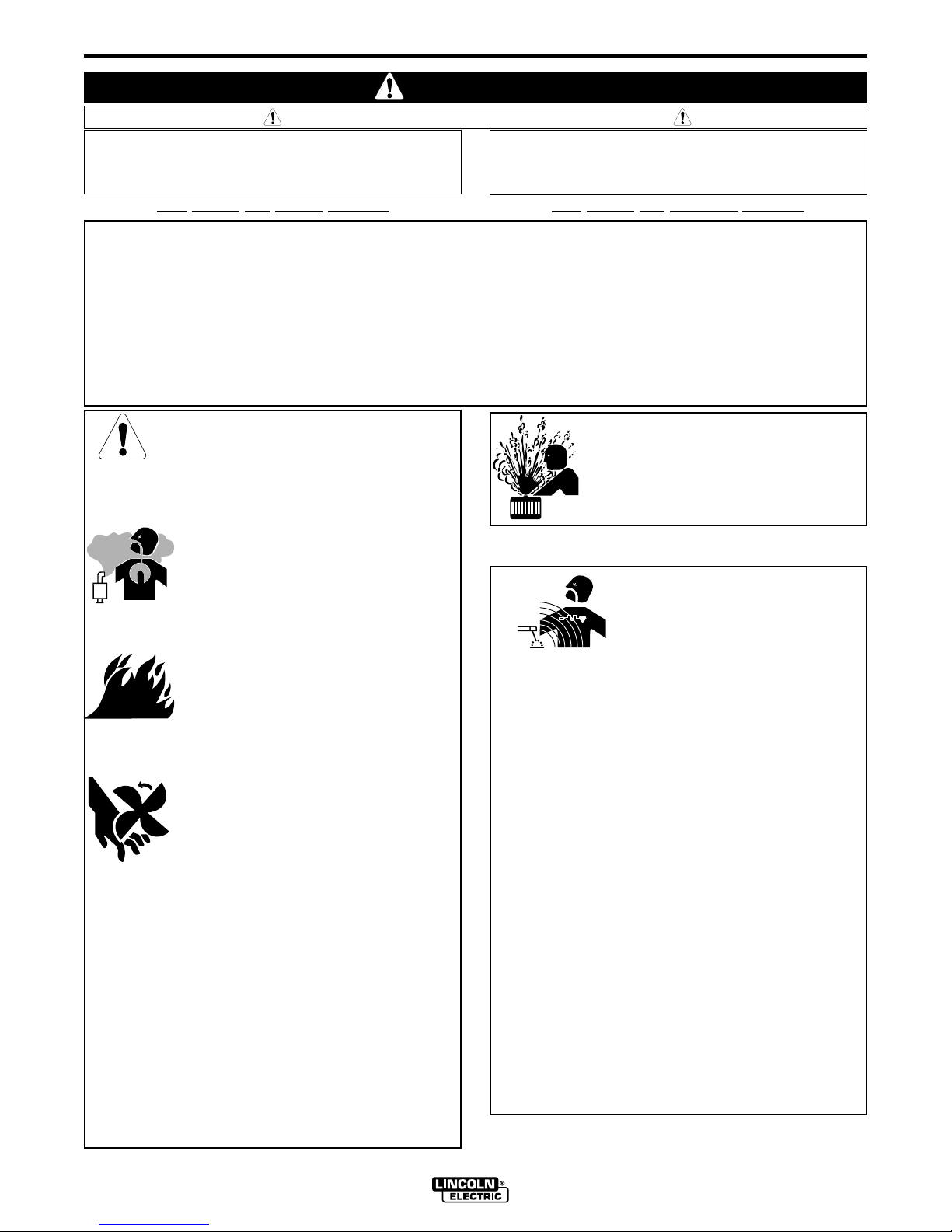
SAFETY
i
ARC WELDING CAN BE HAZARDOUS. PROTECT YOURSELF AND OTHERS FROM POSSIBLE SERIOUS INJURY OR DEATH.
KEEP CHILDREN AWAY. PACEMAKER WEARERS SHOULD CONSULT WITH THEIR DOCTOR BEFORE OPERATING.
Read and understand the following saf ety highlights.For additional saf ety inf ormation, it is strongly recommended that you purchase a copy of “Safety in Welding & Cutting - ANSI Standard Z49.1” from the American Welding Society, P.O. Box 351040,
Miami, Florida 33135 or CSA Standard W117.2-1974. A Free copy of “Arc Welding Safety”booklet E205 is available from the
Lincoln Electric Company, 22801 St. Clair Avenue, Cleveland, Ohio 44117-1199.
BE SURE THAT ALL INSTALLATION, OPERATION, MAINTENANCE AND REPAIR PROCEDURES ARE
PERFORMED ONLY BY QUALIFIED INDIVIDUALS.
WARNING
Mar ‘95
ELECTRIC AND
MAGNETIC FIELDS
may be dangerous
2.a. Electric current flowing through any conductor causes
localized Electric and Magnetic Fields (EMF). Welding
current creates EMF fields around welding cables and
welding machines
2.b. EMF fields may interfere with some pacemakers, and
welders having a pacemaker should consult their physician
before welding.
2.c. Exposure to EMF fields in welding may have other health
effects which are now not known.
2.d. All welders should use the following procedures in order to
minimize exposure to EMF fields from the welding circuit:
2.d.1.
Route the electrode and work cables together - Secure
them with tape when possible.
2.d.2. Never coil the electrode lead around your body.
2.d.3. Do not place your body between the electrode and
work cables. If the electrode cable is on your right
side, the work cable should also be on your right side.
2.d.4. Connect the work cable to the workpiece as close as
possible to the area being welded.
2.d.5. Do not work next to welding power source.
1.h. To avoid scalding, do not remove the
radiator pressure cap when the engine is
hot.
CALIFORNIA PROPOSITION 65 WARNINGS
Diesel engine exhaust and some of its constituents
are known to the State of California to cause cancer, birth defects, and other reproductive harm.
The engine exhaust from this product contains
chemicals known to the State of California to cause
cancer, birth defects, or other reproductive harm.
The Above For Diesel Engines
The Above For Gasoline Engines
Page 3

ii
SAFETY
ii
ARC RAYS can burn.
4.a. Use a shield with the proper filter and cover
plates to protect your eyes from sparks and
the rays of the arc when welding or observing
open arc welding. Headshield and filter lens
should conform to ANSI Z87. I standards.
4.b. Use suitable clothing made from durable flame-resistant
material to protect your skin and that of your helpers from
the arc rays.
4.c. Protect other nearby personnel with suitable, non-flammable
screening and/or warn them not to watch the arc nor expose
themselves to the arc rays or to hot spatter or metal.
ELECTRIC SHOCK can kill.
3.a. The electrode and work (or ground) circuits
are electrically “hot” when the welder is on.
Do not touch these “hot” parts with your bare
skin or wet clothing. Wear dry, hole-free
gloves to insulate hands.
3.b. Insulate yourself from work and ground using dry insulation.
Make certain the insulation is large enough to cover your full
area of physical contact with work and ground.
In addition to the normal safety precautions, if welding
must be performed under electrically hazardous
conditions (in damp locations or while wearing wet
clothing; on metal structures such as floors, gratings or
scaffolds; when in cramped positions such as sitting,
kneeling or lying, if there is a high risk of unavoidable or
accidental contact with the workpiece or ground) use
the following equipment:
• Semiautomatic DC Constant Voltage (Wire) Welder.
• DC Manual (Stick) Welder.
• AC Welder with Reduced Voltage Control.
3.c. In semiautomatic or automatic wire welding, the electrode,
electrode reel, welding head, nozzle or semiautomatic
welding gun are also electrically “hot”.
3.d. Always be sure the work cable makes a good electrical
connection with the metal being welded. The connection
should be as close as possible to the area being welded.
3.e. Ground the work or metal to be welded to a good electrical
(earth) ground.
3.f.
Maintain the electrode holder, work clamp, welding cable and
welding machine in good, safe operating condition.Replace
damaged insulation.
3.g. Never dip the electrode in water for cooling.
3.h. Never simultaneously touch electrically “hot” parts of
electrode holders connected to two welders because voltage
between the two can be the total of the open circuit voltage
of both welders.
3.i. When working above floor level, use a safety belt to protect
yourself from a fall should you get a shock.
3.j. Also see Items 6.c. and 8.
FUMES AND GASES
can be dangerous.
5.a.Welding may produce fumes and gases
hazardous to health. Avoid breathing these
fumes and gases.When welding, keep
your head out of the fume. Use enough
ventilation and/or exhaust at the arc to keep
fumes and gases away from the breathing zone. When
welding with electrodes which require special
ventilation such as stainless or hard facing (see
instructions on container or MSDS) or on lead or
cadmium plated steel and other metals or coatings
which produce highly toxic fumes, keep exposure as
low as possible and below Threshold Limit Values (TLV)
using local exhaust or mechanical ventilation. In
confined spaces or in some circumstances, outdoors, a
respirator may be required. Additional precautions are
also required when welding on galvanized steel.
5.b.
Do not weld in locations near chlorinated hydrocarbon
vapors
coming from degreasing, cleaning or spraying operations.
The heat and rays of the arc can react with solvent vapors
to
form phosgene, a highly toxic gas, and other irritating
products.
5.c. Shielding gases used for arc welding can displace air and
cause injury or death. Always use enough ventilation,
especially in confined areas, to insure breathing air is safe.
5.d. Read and understand the manufacturer’s instructions for this
equipment and the consumables to be used, including the
material safety data sheet (MSDS) and follow your
employer’s safety practices. MSDS forms are available from
your welding distributor or from the manufacturer.
5.e. Also see item 1.b.
Mar ‘95
Page 4
FOR ELECTRICALLY
powered equipment.
8.a.Turn off input power using the disconnect
switch at the fuse box before working on
the equipment.
8.b. Install equipment in accordance with the U.S. National
Electrical Code, all local codes and the manufacturer’s
recommendations.
8.c. Ground the equipment in accordance with the U.S. National
Electrical Code and the manufacturer’s recommendations.
CYLINDER may explode
if damaged.
7.a. Use only compressed gas cylinders
containing the correct shielding gas for the
process used and properly operating
regulators designed for the gas and
pressure used. All hoses, fittings, etc. should be suitable for
the application and maintained in good condition.
7.b. Always keep cylinders in an upright position securely
chained to an undercarriage or fixed support.
7.c. Cylinders should be located:
•Away from areas where they may be struck or subjected to
physical damage.
• A safe distance from arc welding or cutting operations and
any other source of heat, sparks, or flame.
7.d. Never allow the electrode, electrode holder or any other
electrically “hot” parts to touch a cylinder.
7.e. Keep your head and face away from the cylinder valve outlet
when opening the cylinder valve.
7.f. Valve protection caps should always be in place and hand
tight except when the cylinder is in use or connected for
use.
7.g. Read and follow the instructions on compressed gas
cylinders, associated equipment, and CGA publication P-l,
“Precautions for Safe Handling of Compressed Gases in
Cylinders,” available from the Compressed Gas Association
1235 Jefferson Davis Highway, Arlington, VA 22202.
iii
SAFETY
iii
Mar ‘95
WELDING SPARKS can
cause fire or explosion.
6.a.
Remove fire hazards from the welding area.
If this is not possible, cover them to prevent
the welding sparks from starting a fire.
Remember that welding sparks and hot
materials from welding can easily go through small cracks
and openings to adjacent areas. Avoid welding near
hydraulic lines. Have a fire extinguisher readily available.
6.b. Where compressed gases are to be used at the job site,
special precautions should be used to prevent hazardous
situations. Refer to “Safety in Welding and Cutting” (ANSI
Standard Z49.1) and the operating information for the
equipment being used.
6.c. When not welding, make certain no part of the electrode
circuit is touching the work or ground. Accidental contact can
cause overheating and create a fire hazard.
6.d. Do not heat, cut or weld tanks, drums or containers until the
proper steps have been taken to insure that such procedures
will not cause flammable or toxic vapors from substances
inside. They can cause an explosion even
though
they have
been “cleaned”. For information, purchase “Recommended
Safe Practices for the
Preparation
for Welding and Cutting of
Containers and Piping That Have Held Hazardous
Substances”, AWS F4.1 from the American Welding Society
(see address above).
6.e. Vent hollow castings or containers before heating, cutting or
welding.They may explode.
6.f.
Sparks and spatter are thrown from the welding arc. Wear oil
free protective garments such as leather gloves, heavy shirt,
cuffless trousers, high shoes and a cap over your hair. Wear
ear plugs when welding out of position or in confined places.
Always wear safety glasses with side shields when in a
welding area.
6.g. Connect the work cable to the work as close to the welding
area as practical. Work cables connected to the building
framework or other locations away from the welding area
increase the possibility of the welding current passing
through lifting chains, crane cables or other alternate circuits.
This can create fire hazards or overheat lifting chains or
cables until they fail.
6.h. Also see item 1.c.
Page 5
TABLE OF CONTENTS
LT-7 TRACTOR
Theory of Operation . . . . . . . . . . . . . . . . . . . . . . . . . . . . . . . . .Section A
General Description . . . . . . . . . . . . . . . . . . . . . . . . . . . . . . . . . . . .A-1
Input Power Circuits . . . . . . . . . . . . . . . . . . . . . . . . . . . . . . . . . . . .A-1
Control Logic and Travel Boards . . . . . . . . . . . . . . . . . . . . . . . . . . .A-2
Variable Voltage Board . . . . . . . . . . . . . . . . . . . . . . . . . . . . . . . . . .A-3
Troubleshooting and Repair . . . . . . . . . . . . . . . . . . . . . . . . . . .Section B
How to Use Troubleshooting Guide . . . . . . . . . . . . . . . . . . . . . . . . .B-2
PC Board Troubleshooting Procedures . . . . . . . . . . . . . . . . . . . . . .B-3
Troubleshooting Guide . . . . . . . . . . . . . . . . . . . . . . . . . . . . . . . . . .B-4
P.C. Board Status Lights . . . . . . . . . . . . . . . . . . . . . . . . . . . . . . . .B-21
Wire Drive Motor Test . . . . . . . . . . . . . . . . . . . . . . . . . . . . . . . . . .B-24
Travel Motor Test . . . . . . . . . . . . . . . . . . . . . . . . . . . . . . . . . . . . . .B-26
Wire Drive Motor Removal and Replacement . . . . . . . . . . . . . . . .B-30
Diagrams . . . . . . . . . . . . . . . . . . . . . . . . . . . . . . . . . . . . . . . . . .Section C
M15342 Connection Schematic . . . . . . . . . . . . . . . . . . . . . . . . . . . .C-1
L7460 Control Box Wiring Diagram . . . . . . . . . . . . . . . . . . . . . . . . .C-2
iviv
WARNING
ELECTRIC SHOCK can kill.
• Never work on the inside of the machine without removing the
input power.You can receive a life threatening electrical shock if
you fail to do this. Only qualified technicians should perform
installation, maintenance, and troubleshooting work on the
machine.
Page 6
THEORY OF OPERATION
A-1A-1
LT-7 TRACTOR
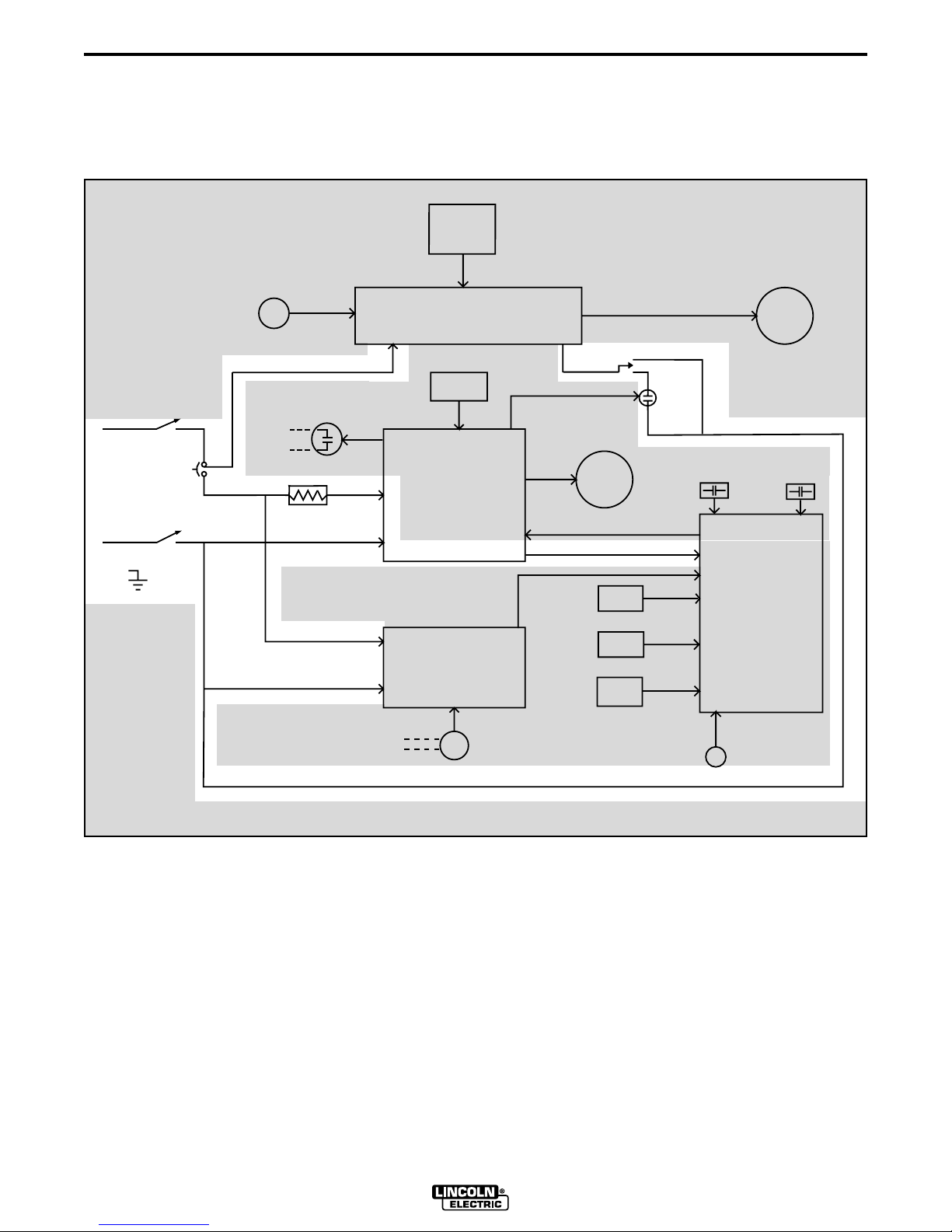
FIGURE E.1 - 115VAC INPUT POWER CIRCUITS
GENERAL DESCRIPTION
The LT-7 tractor is a compact, lightweight, DC, single arc tractor. It is capable of operating with 3/32” through
3/16” electrode with a current carrying capacity of 1000 amps. The LT-7 has a travel range from 6 to 70 inches
per minute.
INPUT POWER CIRCUITS
The LT7 is powered by 115VAC which is usually supplied from the welding power source. The 115VAC is
applied to the travel board. This voltage is also coupled
to the control box circuitry through the on/off power
switch and a 3 amp circuit breaker. The input power is
then applied to the the variable voltage board and,
through resistor R1, to the control board. The 115VAC
is rectified and regulated by the control board which
supplies 24VDC to the logic board.
GLP WELD CURRENT
SENSING REED
2CR
TRAVEL
RELAY
TRAVEL
SWITCH
TRAVEL
MOTOR
TRAVEL BOARD
TRAVEL
SPEED
CONTROL
POWER SOURCE
CONTACT RELAY
R1
CIRCUIT
BREAKER
115VAC
FROM
WELDING
POWER
SOURCE
INCH UP
SWITCH
WIRE
DRIVE
MOTOR
START
SWITCH
STOP
SWITCH
INCH
DOWN
SWITCH
WIRE
SPEED
CONTROL
LOGIC
BOARD
CONTROL
BOARD
VARIABLE VOLTAGE
BOARD
ARC
VOLTAGE
METER
115VAC
115VAC
115VAC
115VAC
115VAC 115VAC
115VAC
115VAC
LOGIC CONTROL SIGNALS
ARC VOLTAGE SENSING SIGNALS
24VDC
ELECTRODE
WORK
VOLTAGE
SENSING
LEADS
REED
SWITCH 4CR
SWITCH 3CR
TRAVEL
DIRECTION
SWITCH
CONTROL
1CR
#2
#4
{
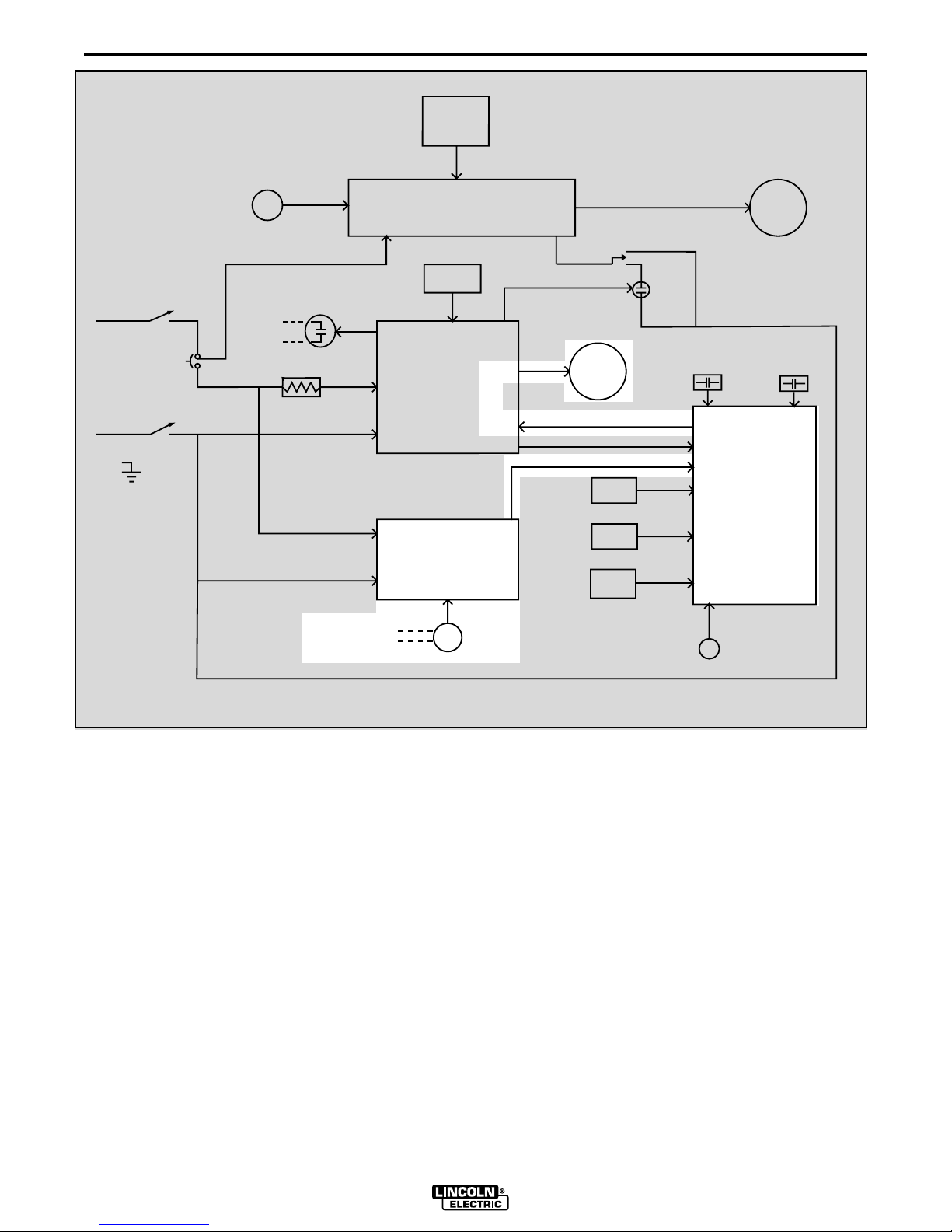
NOTE: Unshaded areas of the Block Logic Diagram are the subject of discussion
Page 7
THEORY OF OPERATION
A-2A-2
LT-7 TRACTOR
Upon receiving commands from the user operated
switches or potentiomenters the logic board sends the
appropriate signal to the control board which then drives the wire feed motor to the correct speed and direction. When the start signal is received by the control
board the power source contact relay(1CR) is energized as well as the trav el rela y(2CR) and the wire drive
motor. When weld current closes reed switch 3CR the
logic board directs the control board to change the wire
feed speed from the preset inch speed to the welding
feed speed set by the wire speed control potentiometer. Reed switch 4CR protects the internal grounding
wire circuitry. In the event that abnormally high current
was to flow in the grounding lead system the 4CR reed
switch would close, signaling the logic board to stop the
welding procedure. The inch up switch, which is coupled directly to the control board, dictates that the wire
drive motor reverse direction and back the electrode
wire away from the work piece.
Travel speed, direction and mode (either manual or
auto) are determined by the settings of the three controls connected to the travel board. The travel board
then applies the correct voltage and polarity to the travel motor to satisfy the control settings.
CONTROL, LOGIC AND TRAVEL
BOARDS
FIGURE E.2 - CONTROL LOGIC AND TRAVEL BOARDS
GLP WELD CURRENT
SENSING REED
2CR
TRAVEL
RELAY
TRAVEL
SWITCH
TRAVEL
MOTOR
TRAVEL BOARD
TRAVEL
SPEED
CONTROL
POWER SOURCE
CONTACT RELAY
R1
CIRCUIT
BREAKER
115VAC
FROM
WELDING
POWER
SOURCE
INCH UP
SWITCH
WIRE
DRIVE
MOTOR
START
SWITCH
STOP
SWITCH
INCH
DOWN
SWITCH
WIRE
SPEED
CONTROL
LOGIC
BOARD
CONTROL
BOARD
VARIABLE VOLTAGE
BOARD
ARC
VOLTAGE
METER
115VAC
115VAC
115VAC
115VAC
115VAC 115VAC
115VAC
115VAC
LOGIC CONTROL SIGNALS
ARC VOLTAGE SENSING SIGNALS
24VDC
ELECTRODE
WORK
VOLTAGE
SENSING
LEADS
REED
SWITCH 4CR
SWITCH 3CR
TRAVEL
DIRECTION
SWITCH
CONTROL
1CR
#2
#4
{
NOTE: Unshaded areas of the Block Logic Diagram are the subject of discussion
Page 8
THEORY OF OPERATION
A-3A-3
LT-7 TRACTOR
Arc voltage is monitored by the voltmeter and variable
voltage board. When the LT7 tractor is being operated
in the constant current mode the variable voltage
board is essential in the control of the wire feed speed.
As the arc length changes the arc voltage will also
change. The variable voltage board recognizes this
change and signals the logic board to either increase or
decrease the wire feed speed. This function is necessary to maintain a constant electrode arc length and a
stable and high quality weld.
The variable voltage board also generates a low voltage which is applied to the electrode during the inch
down mode. When the electrode makes contact with
the work piece this low voltage is “loaded down” thus
signaling the control circuitry to stop the wire feed
motor. This feature allows the operator to utilize “work
touch sensing”.
FIGURE E.3 - VARIABLE VOLTAGE BOARD
V ARIABLE V OLT A GE BOARD
GLP WELD CURRENT
SENSING REED
2CR
TRAVEL
RELAY
TRAVEL
SWITCH
TRAVEL
MOTOR
TRAVEL BOARD
TRAVEL
SPEED
CONTROL
POWER SOURCE
CONTACT RELAY
R1
CIRCUIT
BREAKER
115VAC
FROM
WELDING
POWER
SOURCE
INCH UP
SWITCH
WIRE
DRIVE
MOTOR
START
SWITCH
STOP
SWITCH
INCH
DOWN
SWITCH
WIRE
SPEED
CONTROL
LOGIC
BOARD
CONTROL
BOARD
VARIABLE VOLTAGE
BOARD
ARC
VOLTAGE
METER
115VAC
115VAC
115VAC
115VAC
115VAC 115VAC
115VAC
115VAC
LOGIC CONTROL SIGNALS
ARC VOLTAGE SENSING SIGNALS
24VDC
ELECTRODE
WORK
VOLTAGE
SENSING
LEADS
REED
SWITCH 4CR
SWITCH 3CR
TRAVEL
DIRECTION
SWITCH
CONTROL
1CR
#2
#4
{
NOTE: Unshaded areas of the Block Logic Diagram are the subject of discussion
Page 9

NOTES
A-4A-4
LT-7 TRACTOR
Page 10

B-1
TROUBLESHOOTING AND REPAIR
B-1
LT-7 TRACTOR
If for any reason you do not understand the test procedures or are unable to perform the
tests/repairs safely, contact the Lincoln Electric Ser vice Department for technical
troubleshooting assistance before you proceed. Call 216-383-2531 or 1-800-833-9353.
Service and Repair should only be performed by Lincoln Electric Factory Trained
Personnel. Unauthorized repairs performed on this equipment may result in danger
to the technician and machine operator and will invalidate your factory warranty. For
your safety and to avoid Electrical Shock, please observe all safety notes and
precautions detailed throughout this manual.
This Troubleshooting Guide is provided to
help you locate and repair possible machine
malfunctions. Simply follow the three step
procedure below.
Step 1. LOCATE PROBLEM (SYMPTOM).
Look under the column labeled “PROBLEM
(SYMPTOMS)”. This column describes
possible symptoms that the machinery may
exhibit. Find the listing that best describes
the symptom that the machine is exhibiting.
Symptoms are grouped according to:
function problems and travel problems.
Step 2. PERFORM EXTERNAL TESTS.
The second column labeled “FIELD
COURSE OF ACTION” lists the basic
possibilities that may contribute to the
machine symptom. Perform these
tests/checks in the order listed.
Step 3. PERFORM COMPONENT TESTS.
The last column labeled “RECOMMENDED
SHOP COURSE OF ACTION”lists the most
likely components that may have failed in
your machine. It also specifies the
appropriate test procedure to verify that the
subject component is either bad or good. If
there are a number of possible components,
check the components in the order listed to
eliminate one possibility at a time until you
locate the cause of your problem.
All the necessary test specifications and
repair procedures are described in detail
following the troubleshooting guide. All
electrical test points, terminal strips,
junctions, etc., can be found on the
electrical wiring diagrams and schematics
in the Electrical Diagram Section.
WARNING
CAUTION
How To Use T r oubleshooting Guide
Page 11
B-2
TROUBLESHOOTING AND REPAIR
B-2
LT-7 TRACTOR
Sometimes machine failures appear to be due
to PC board failures. These problems can
sometimes be traced to poor electrical connections. To avoid problems when troubleshooting and replacing PC boards, please
use the following procedure:
1. Determine to the best of your technical
ability that the PC board is the most
likely component causing the failure
symptom.
2. Check for loose connections at the PC
board to assure that the PC board is
properly connected.
3. If the problem persists, replace the
suspect PC board using standard
practices to avoid static electrical
damage and electrical shock. Read the
warning inside the static resistant bag
and perform the following procedures:
PC board can be
damaged by static
electricity.
- Remove your body’s
static charge before
opening the staticshielding bag. Wear an
anti-static wrist strap. For
safety, use a 1 Meg ohm
resistive cord connected
to a grounded part of the
equipment frame.
- If you don’t have a wrist
strap, touch an unpainted, grounded, part of the equipment
frame. Keep touching the frame to prevent
static build-up. Be sure not to touch any
electrically live parts at the same time.
ELECTRIC SHOCK
can kill.
•
Have an electrician
install and service this
equipment. Turn the input
power OFF at the fuse box
before working on equipment. Do not touch
electrically hot parts.
- Tools which come in contact with the PC
board must be either conductive, anti-static or
static-dissipative.
- Remove the PC board from the static-shielding bag and place it directly into the equipment.Don’t set the PC board on or near paper,
plastic or cloth which could have a static
charge. If the PC board can’t be installed
immediately, put it back in the static-shielding
bag.
- If the PC board uses protective shorting
jumpers, don’t remove them until installation is
complete.
- If you return a PC board to The Lincoln
Electric Company for credit, it must be in the
static-shielding bag. This will prevent further
damage and allow proper failure analysis.
4. Test the machine to determine if the
failure symptom has been corrected by
the replacement PC board.
NOTE: It is desirable to have a spare
(known good) PC board available for PC
board troubleshooting.
NOTE: Allow the machine to heat up so that
all electrical components can reach their
operating temperature.
5. Remove the replacement PC board and
substitute it with the original PC board
to recreate the original problem.
a. If the original problem does not
reappear by substituting the original
board, then the PC board was not
the problem.Continue to look for bad
connections in the control wiring
harness, junction blocks, and
terminal strips.
b. If the original problem is recreated by
the substitution of the original board,
then the PC board was the problem.
Reinstall the replacement PC board
and test the machine.
6. Always indicate that this procedure was
followed when warranty reports are to
be submitted.
NOTE: Following this procedure and writing
on the warranty report, “INSTALLED AND
SWITCHED PC BOARDS TO VERIFY PROBLEM,” will help avoid denial of legitimate PC
board warranty claims.
PC BOARD TROUBLESHOOTING PROCEDURES
ATTENTION
Static-Sensitive
Devices
Handle only at
Static-Safe
Workstations
Reusable
Container
Do Not Destroy
WARNING
CAUTION
Page 12
TROUBLESHOOTING AND REPAIR
Observe Safety Guidelines
detailed in the beginning of this manual.
Troubleshooting Guide – See Wiring Diagrams for location of specified
components. See Wiring Diagrams for troubleshooting of specific circuits.
B-3B-3
LT-7 TRACTOR
If for any reason you do not understand the test procedures or are unab le to perform the tests/repairs safely, contact the Lincoln
Electric Service Department for electrical technical troubleshooting assistance before y ou proceed.Call 216-383-2531 or 1-800833-9353
CA UTION
FUNCTIONAL PROBLEMS
PROBLEMS
(SYMPTOMS)
FIELD
COURSE OF ACTION
RECOMMENDED SHOP
COURSE OF ACTION
Wire feeds whenever “Power
Switch” (S1) is turned “ON”.
1. Check the “Start Switch”(S5).
Make certain it is not stuck
closed.
2. Check the “Inch Down Switch”
(S4). Make certain it is not
stuck closed.
3. Check the “Inch Up Switch”
(S3). Make certain it is not
stuck closed.
1. If light 1B on the control board
is NOT on, then the control
board may be faulty. Replace.
2. If lights 1B and 1A are both
“ON” then remove lead #593
from the Inch Up switch(S3). If
the problem is resolved the lead
or the switch is faulty. If light 1A
stays on when lead #593 is
removed from the Inch Up switch
the control board may be faulty.
Replace.
3. If lights 1B, on the control
board, and 2B on the logic
board, are both “ON” then
remove lead #581 from the Start
switch(S5). If the problem is
resolved the lead or the switch is
faulty. If light 2B stays on when
lead #581 is removed from the
Start Switch the logic board may
be faulty. Replace.
4. If lights 1B, on the control
board, and 2J on the logic board
are both “ON” then remove lead
#592 from the Inch Down switch
(S4). If the problem is resolved
the lead or the switch is faulty. If
light 2J stays on when lead #592
is removed from the Inch Down
switch the logic board may be
faulty. Replace.
Page 13

TROUBLESHOOTING AND REPAIR
Observe Safety Guidelines
detailed in the beginning of this manual.
Troubleshooting Guide – See Wiring Diagrams for location of specified
components. See Wiring Diagrams for troubleshooting of specific circuits.
B-4B-4
LT-7 TRACTOR
If for any reason you do not understand the test procedures or are unab le to perform the tests/repairs safely, contact the Lincoln
Electric Service Department for electrical technical troubleshooting assistance before y ou proceed.Call 216-383-2531 or 1-800833-9353
CA UTION
FUNCTIONAL PROBLEMS
PROBLEMS
(SYMPTOMS)
FIELD
COURSE OF ACTION
RECOMMENDED SHOP
COURSE OF ACTION
Wire does not feed. No inch up or
down. Wire does NOT feed when
start switch is activated.
1. Make sure the Power Switch
(S1) is on and functioning properly.
2. Check the circuit breaker locat-
ed on the front cover. If tr ipped
- reset. If circuit breaker repeatedly trips consult appropriate
(“PROBLEMS (SYMPTOMS”).
3. Open the front cover and inner
panel to check if any of the
LEDS on the printed circuit
boards are lit. If none of the
LEDS are lit, this is an indication that the LT7 is NOT receiving any power. Check the 2/10
amp fuse on the control board.
Also make sure that 115VAC is
being received on leads #531
and #532. See wir ing diagram.
1. Check lights 1C and 1D on the
control board. If both lights are
lit at the same time replace the
control board.
2. Press the inch up switch. Lights
1D and 1E, on the control board
should be lit. If they are NOT lit
the control board may be faulty.
3. If light 1D and 1E are lit and the
wire drive motor does not turn
check the continuity of leads
#539, #541, #626 and #627
from the control board to the
wire drive motor.
4. Perform the
Wire Drive Motor
Test
.
Page 14

TROUBLESHOOTING AND REPAIR
Observe Safety Guidelines
detailed in the beginning of this manual.
Troubleshooting Guide – See Wiring Diagrams for location of specified
components. See Wiring Diagrams for troubleshooting of specific circuits.
B-5B-5
LT-7 TRACTOR
If for any reason you do not understand the test procedures or are unab le to perform the tests/repairs safely, contact the Lincoln
Electric Service Department for electrical technical troubleshooting assistance before y ou proceed.Call 216-383-2531 or 1-800833-9353
CA UTION
FUNCTIONAL PROBLEMS
PROBLEMS
(SYMPTOMS)
FIELD
COURSE OF ACTION
RECOMMENDED SHOP
COURSE OF ACTION
The wire will not feed and the circuit breaker trips when the inch or
start switches are pressed.
1. Reset the circuit breaker and
observe lights 1C and 1D on
the control board with the unit at
idle. (Not attempting to feed
wire). Light 1C should be OFF
and light 1D should be ON. If
both lights are OFF remove
power and check F101 field
fuse. (1/2amp).
2. If both lights are ON the control
board may be faulty.
3. The following conditions may
cause the F101 fuse to fail.
•Faulty wire drive motor
•Incorrect welding procedure.
•A low impedance across the
arc voltage sensing leads (#21
and #67).
•A defective control board.
1. If when at idle light 1D is ON
and light 1C is OFF then perform
the
Wire Drive Motor Test
.
Page 15

TROUBLESHOOTING AND REPAIR
Observe Safety Guidelines
detailed in the beginning of this manual.
Troubleshooting Guide – See Wiring Diagrams for location of specified
components. See Wiring Diagrams for troubleshooting of specific circuits.
B-6B-6
LT-7 TRACTOR
If for any reason you do not understand the test procedures or are unab le to perform the tests/repairs safely, contact the Lincoln
Electric Service Department for electrical technical troubleshooting assistance before y ou proceed.Call 216-383-2531 or 1-800833-9353
CA UTION
FUNCTIONAL PROBLEMS
PROBLEMS
(SYMPTOMS)
FIELD
COURSE OF ACTION
RECOMMENDED SHOP
COURSE OF ACTION
The wire will not feed when the
start switch is pressed. There is
not a voltage indicated on the LT7
voltmeter. The wire does inch up
and down properly.
1. If light 2M on the logic board is
lit the ground lead protector has
tripped. Make sure the LT7 head
or electrode is NOT contacting
the LT7 frame or control box.
Note that conductive dirt or shavings can cause the ground lead
protector to trip. Remove power to
unit and clear fault.
2. While pressing the star t switch
observe light 2B. It should be
lit. If not the start switch (S5) or
associated wires may be faulty.
See wiring diagram.
1. If light 2B is on when the start
switch is pressed and light 2M
does NOT light then the logic
board may be faulty.
Page 16

TROUBLESHOOTING AND REPAIR
Observe Safety Guidelines
detailed in the beginning of this manual.
Troubleshooting Guide – See Wiring Diagrams for location of specified
components. See Wiring Diagrams for troubleshooting of specific circuits.
B-7B-7
LT-7 TRACTOR
If for any reason you do not understand the test procedures or are unab le to perform the tests/repairs safely, contact the Lincoln
Electric Service Department for electrical technical troubleshooting assistance before y ou proceed.Call 216-383-2531 or 1-800833-9353
CA UTION
FUNCTIONAL PROBLEMS
PROBLEMS
(SYMPTOMS)
FIELD
COURSE OF ACTION
RECOMMENDED SHOP
COURSE OF ACTION
The wire will NOT inch down but
does inch up properly.
When the start switch is pressed
the wire feeds down properly.
1. While pressing the inch down
switch observe light 2J. It
should be lit. If not the inch
down switch (S4) or associated
wires may be faulty. See wiring
diagram.
2. If the LT7 is in the constant voltage (CV) mode and light 2J
does light then the logic board
may be faulty.
1. If the LT7 is in the variable voltage (VV) mode, and a variable
voltage board is installed, disconnect lead #21 from the terminal strip. Tur n on input power
and while pressing the inch
down switch observe light 3A. If
light 3A does NOT light the variable voltage board may be
faulty. Replace board and
reconnect lead #21.
If light 3A does light, with lead
#21 disconnected, the resistance across leads #21 and
#67 is too low. The resistance
must be above 500 ohms. The
low resistance could be caused
by the following:
• A lead or object external to
the power source or LT7
causing a low resistance
between leads #21 and #67.
• A non-Lincoln power source
not designed with the
required impedance.
• A defective power source.
Page 17

TROUBLESHOOTING AND REPAIR
Observe Safety Guidelines
detailed in the beginning of this manual.
Troubleshooting Guide – See Wiring Diagrams for location of specified
components. See Wiring Diagrams for troubleshooting of specific circuits.
B-8B-8
LT-7 TRACTOR
If for any reason you do not understand the test procedures or are unab le to perform the tests/repairs safely, contact the Lincoln
Electric Service Department for electrical technical troubleshooting assistance before y ou proceed.Call 216-383-2531 or 1-800833-9353
CA UTION
FUNCTIONAL PROBLEMS
PROBLEMS
(SYMPTOMS)
FIELD
COURSE OF ACTION
RECOMMENDED SHOP
COURSE OF ACTION
The wire will NOT inch down but
inches up properly. When the star t
switch is pressed the wire does not
feed.
1. Press the inch down switch and
observe light 1B on the control
board. If light 1B is lit and the
motor does not activate the control
board may be faulty.
1. If light 1B does NOT light,
when the inch down switch is
pressed, measure the DC voltage from lead #586 to lead
#539 while pressing the inch
down switch. Normal voltage
is 12 to 15VDC.
•If normal voltage is indicated
the control board may be
faulty.
•If normal voltage is not pre-
sent the logic board may be
faulty.
Page 18

TROUBLESHOOTING AND REPAIR
Observe Safety Guidelines
detailed in the beginning of this manual.
Troubleshooting Guide – See Wiring Diagrams for location of specified
components. See Wiring Diagrams for troubleshooting of specific circuits.
B-9B-9
LT-7 TRACTOR
If for any reason you do not understand the test procedures or are unab le to perform the tests/repairs safely, contact the Lincoln
Electric Service Department for electrical technical troubleshooting assistance before y ou proceed.Call 216-383-2531 or 1-800833-9353
CA UTION
FUNCTIONAL PROBLEMS
PROBLEMS
(SYMPTOMS)
FIELD
COURSE OF ACTION
RECOMMENDED SHOP
COURSE OF ACTION
The wire will not inch down. The
wire inches up properly. When the
start switch is pressed the wire
feeds up instead of down.
1. Check the connections between
the power source and LT7 for
loose or incorrect connections.
2. Check the leads connected to
the variable voltage board for
loose or faulty connections.
3. While pressing the inch down
switch observe light 3A on the
variable voltage board.
• If light 3A is NOT lit check
leads #21 and #67 for continuity to the voltage board.
4. If while pressing the inch down
switch light 3A does light also
check light 2E on the logic
board.
• If light 3A and 2E are both lit
the control board may be
faulty.
• If light 3A is lit but light 2E is
NOT lit the logic board may
be faulty.
1. Check lead #21 for continuity
(zero ohms) to “work”.
2. Check lead #67 for continuity
(zero ohms) to electrode.
Page 19

TROUBLESHOOTING AND REPAIR
Observe Safety Guidelines
detailed in the beginning of this manual.
Troubleshooting Guide – See Wiring Diagrams for location of specified
components. See Wiring Diagrams for troubleshooting of specific circuits.
B-10B-10
LT-7 TRACTOR
If for any reason you do not understand the test procedures or are unab le to perform the tests/repairs safely, contact the Lincoln
Electric Service Department for electrical technical troubleshooting assistance before y ou proceed.Call 216-383-2531 or 1-800833-9353
CA UTION
FUNCTIONAL PROBLEMS
PROBLEMS
(SYMPTOMS)
FIELD
COURSE OF ACTION
RECOMMENDED SHOP
COURSE OF ACTION
When attempting to “cold start” the
wire does not stop feeding when it
touches the work piece.
The wire will not inch up. The wire
inches down properly.
1. Make certain a variable voltage
board is installed and connected correctly.
2. The jumper on the variable voltage board must be connected
to the “H” pin.
3. The logic board may be faulty.
4. The variable voltage board may
be faulty.
1. With LT7 at idle (not feeding
wire) observe light 1D on the
control board. The light should
be lit. If light is NOT lit the control board may be faulty.
2. While pressing the inch up
switch observe light 1A on the
control board. If light 1A does
NOT light check the inch up
switch and associated leads.
(#593 and #539) See wiring
diagram.
3. If light 1A is lit the control
board may be faulty.
1. Check lead #21 for continuity
(zero ohms) to “work”.
2. Check lead #67 for continuity
(zero ohms) to electrode.
1. Perform the
Wire Drive Motor
Test
.
Page 20

TROUBLESHOOTING AND REPAIR
Observe Safety Guidelines
detailed in the beginning of this manual.
Troubleshooting Guide – See Wiring Diagrams for location of specified
components. See Wiring Diagrams for troubleshooting of specific circuits.
B-11B-11
LT-7 TRACTOR
If for any reason you do not understand the test procedures or are unab le to perform the tests/repairs safely, contact the Lincoln
Electric Service Department for electrical technical troubleshooting assistance before y ou proceed.Call 216-383-2531 or 1-800833-9353
CA UTION
FUNCTIONAL PROBLEMS
PROBLEMS
(SYMPTOMS)
FIELD
COURSE OF ACTION
RECOMMENDED SHOP
COURSE OF ACTION
The wire feeds up with either inch
switch.
The wire feeds down with either
inch switch.
1. While pressing the inch down
switch observe light 2E on the
logic board. If light 2E does
NOT light the logic board may
be faulty.
2. If light 2E does light the control
board may be faulty.
1. With the LT7 at idle (not feeding
wire) observe light 2E on the
logic board. It should be off. If
light 2E is on the logic board
may be faulty.
2. If light 2E is off the control
board may be faulty.
1. Check the wiring to the inch
down switch. See wiring diagram.
2. Check the wiring between the
logic board and the control
board. See wiring diagram.
1. Check the wiring to the inch up
switch. See wir ing diagram.
2. Check the wiring between the
logic board and the control
board. See wiring diagram.
Page 21

TROUBLESHOOTING AND REPAIR
Observe Safety Guidelines
detailed in the beginning of this manual.
Troubleshooting Guide – See Wiring Diagrams for location of specified
components. See Wiring Diagrams for troubleshooting of specific circuits.
B-12B-12
LT-7 TRACTOR
If for any reason you do not understand the test procedures or are unab le to perform the tests/repairs safely, contact the Lincoln
Electric Service Department for electrical technical troubleshooting assistance before y ou proceed.Call 216-383-2531 or 1-800833-9353
CA UTION
FUNCTIONAL PROBLEMS
PROBLEMS
(SYMPTOMS)
FIELD
COURSE OF ACTION
RECOMMENDED SHOP
COURSE OF ACTION
The wire feeds at full speed during
the inch mode (only).
The wire feeds at full speed during
the weld mode (only).
1. The logic board may be faulty.
1. Remove electrode from drive
rolls and place a jumper wire
from lead #528 to lead #539 on
the reed switch(CR3) in the
shunt box. Press the start
switch and observe lights 2L
and 2D on the logic board.
Both lights should be on. If light
2D is lit and light 2L is NOT lit
the logic board may be faulty.
2. If light 2D does not light check
continuity (zero ohms) of leads
#528 and #539 from the reed
switch (CR3) to the logic board.
See wiring diagram.
1. Check the wiring between the
logic board and the control board.
See wiring diagram.
2. Perform the
Wire Drive Motor
Test.
1. Check leads #634, #641 and
#642 between wire feed speed
control (R3) and logic board.
2. Check R3 rheostat for correct
resistance (5000 ohms) and
proper function.
Page 22

TROUBLESHOOTING AND REPAIR
Observe Safety Guidelines
detailed in the beginning of this manual.
Troubleshooting Guide – See Wiring Diagrams for location of specified
components. See Wiring Diagrams for troubleshooting of specific circuits.
B-13B-13
LT-7 TRACTOR
If for any reason you do not understand the test procedures or are unab le to perform the tests/repairs safely, contact the Lincoln
Electric Service Department for electrical technical troubleshooting assistance before y ou proceed.Call 216-383-2531 or 1-800833-9353
CA UTION
FUNCTIONAL PROBLEMS
PROBLEMS
(SYMPTOMS)
FIELD
COURSE OF ACTION
RECOMMENDED SHOP
COURSE OF ACTION
The wire feeds at full speed in both
inch and weld modes.
The wire has limited or erratic
speed control in one or more
modes.
1. With the LT7 at idle (not feeding
wire) observe light 2F on the
logic board. If light 2F is lit the
control board may be faulty.
2. If light 2F is not lit the logic
board may be faulty.
1. Make sure the CV-VV switch is
in the CV mode. If the problem
is solved the variable voltage
board may be faulty.
2. The logic board may be faulty.
3. The control board may be faulty.
1. Perform the
Wire Drive Motor
Test
.
1. Perform the
Wire Drive Motor
Test
.
2. Check the wire feed speed control (R3) for resistance and
smooth operation. Normal
resistance is 5000 ohms.
Page 23

TROUBLESHOOTING AND REPAIR
Observe Safety Guidelines
detailed in the beginning of this manual.
Troubleshooting Guide – See Wiring Diagrams for location of specified
components. See Wiring Diagrams for troubleshooting of specific circuits.
B-14B-14
LT-7 TRACTOR
If for any reason you do not understand the test procedures or are unab le to perform the tests/repairs safely, contact the Lincoln
Electric Service Department for electrical technical troubleshooting assistance before y ou proceed.Call 216-383-2531 or 1-800833-9353
CA UTION
FUNCTIONAL PROBLEMS
PROBLEMS
(SYMPTOMS)
FIELD
COURSE OF ACTION
RECOMMENDED SHOP
COURSE OF ACTION
The wire feeds up instead of down
when the start switch is pressed.
There is no voltage reading on LT7
voltmeter. The wire inches up and
down properly.
1. Check for proper connection of
electrode leads and control
cable leads from power source
to LT7.
2. On Lincoln power sources put a
jumper from #2 to #4 on the terminal strip. This activates the
output from the power source.
Test for voltage at the output
terminals of the power source.
If no voltage is indicated then
the power source is faulty.
3. If voltage is present at the
power source output terminals it
should also be present at the
LT7 voltmeter. If not, check
leads #21 and #67 for breaks or
faulty connections.
4. Remove electrode from drive
rolls and press the start switch.
Observe light 2K on the logic
board. It should be lit. If light
2K does NOT light when the
start switch is pressed remove
power to unit. Remove lead
#682 from CR1. Check the
resistance of the coil from the
terminal to lead #510. Normal
resistance is 10,000 ohms. See
wiring diagram.
5. If the relay coil resistance is correct the logic board may be
faulty.
6. If light 2K does light make sure
the relay (CR1) contacts are
making contact.
1. Check lead #21 for continuity
(zero ohms) to “work”.
2. Check lead #67 for continuity
(zero ohms) to electrode.
3. Check leads #2 and #4 for
loose or faulty connections
between relay CR1 and the
control cable receptacle.
Page 24

TROUBLESHOOTING AND REPAIR
Observe Safety Guidelines
detailed in the beginning of this manual.
Troubleshooting Guide – See Wiring Diagrams for location of specified
components. See Wiring Diagrams for troubleshooting of specific circuits.
B-15B-15
LT-7 TRACTOR
If for any reason you do not understand the test procedures or are unab le to perform the tests/repairs safely, contact the Lincoln
Electric Service Department for electrical technical troubleshooting assistance before y ou proceed.Call 216-383-2531 or 1-800833-9353
CA UTION
FUNCTIONAL PROBLEMS
PROBLEMS
(SYMPTOMS)
FIELD
COURSE OF ACTION
RECOMMENDED SHOP
COURSE OF ACTION
No control of power source output
from LT7 tractor. Power source
does have output.
The circuit breaker trips while the
LT7 is at idle (not feeding wire).
1. Check control cable leads for
proper connection to power
source.
2. Make sure the Lincoln power
source is in the remote control
mode.
1. Isolate the problem by unpluging the printed circuit boards
one at a time and checking to
see if circuit breaker trips.
1. Check the continuity of leads
#75, #76 and #77 in the control
cable.
2. Check the resistance and operation of the voltage control
rheostat (R2). Normal resistance is 10,000 ohms.
3. Check the continuity of leads
#75, #76 and #77 from the control rheostat (R2) to the control
cable receptacle.
1. If the problem is not in a printed
circuit board then check the
wiring harness for “shorts” or
grounded leads.
Page 25

TROUBLESHOOTING AND REPAIR
Observe Safety Guidelines
detailed in the beginning of this manual.
Troubleshooting Guide – See Wiring Diagrams for location of specified
components. See Wiring Diagrams for troubleshooting of specific circuits.
B-16B-16
LT-7 TRACTOR
If for any reason you do not understand the test procedures or are unab le to perform the tests/repairs safely, contact the Lincoln
Electric Service Department for electrical technical troubleshooting assistance before y ou proceed.Call 216-383-2531 or 1-800833-9353
CA UTION
FUNCTIONAL PROBLEMS
PROBLEMS
(SYMPTOMS)
FIELD
COURSE OF ACTION
RECOMMENDED SHOP
COURSE OF ACTION
The power source output contactor
does NOT “drop out”. The power
source output terminals are always
electrically hot.
The welding and travel do not stop
when the stop switch is pressed.
1.With the LT7 at idle (not feeding
wire) observe light 2K on the
logic board. It should not be on.
If light 2K IS on the logic board
may be faulty.
2. If light 2K is NOT lit (with the
LT7 at idle) locate and remove
lead #2 on the 1CR relay. If the
power source output contactor
drops out the 1CR relay may be
faulty.
3. If the power source contactor
stays “ON”( output terminals
electrically hot) with #2 lead
removed from 1CR, the problem is in the control cable or the
power source.
1.While pressing the stop switch
observe light 2C. If light 2C is
on the logic board may be faulty.
2. If light 2C is NOT lit (while
pressing the stop switch) check
the stop switch (S6) and associated leads.
Page 26

TROUBLESHOOTING AND REPAIR
Observe Safety Guidelines
detailed in the beginning of this manual.
Troubleshooting Guide – See Wiring Diagrams for location of specified
components. See Wiring Diagrams for troubleshooting of specific circuits.
B-17B-17
LT-7 TRACTOR
If for any reason you do not understand the test procedures or are unab le to perform the tests/repairs safely, contact the Lincoln
Electric Service Department for electrical technical troubleshooting assistance before y ou proceed.Call 216-383-2531 or 1-800833-9353
CA UTION
TRAVEL PROBLEMS
PROBLEMS
(SYMPTOMS)
FIELD
COURSE OF ACTION
RECOMMENDED SHOP
COURSE OF ACTION
The travel motor does not run in
either the “manual” or “automatic”
position.
1. Make sure the circuit breaker is
NOT tripped.
2. Set the travel switch in “manual”
mode. Check the voltage at the
travel board #531 to #632 at the
circuit breaker. Normal is 105
to 130VAC. If the correct voltage is NOT present check the
circuit breaker, the R5 resistor,
the travel switch and the associated wiring. See wiring diagram.
3. If the correct AC voltage IS pre-
sent at leads #531 to #632 then
check the DC voltage at the
travel direction switch (S7).
(Leads #561 to #559). Normal
is 85VDC. with the travel speed
set at maximum. If the correct
DC voltage is NOT present at
leads #561 to #559 the travel
board may be faulty. Also check
the travel speed control (R6)
and the associated wiring. See
wiring diagram
1. Check the DC armature voltage
being applied to the travel
motor. Leads #595 to #594.
Normal is 0 to 85VDC. depending upon the travel speed setting.
(Note: In older units the travel
motor may be a shunt wound
field motor. Normal field voltage is 90 to 110VDC. This
may be measured at leads
#656 to #657. If field voltage is
missing check field fuse F401
on travel board).
2. If the armature voltage is NOT
present at leads #595 to #594
check the travel direction switch
and associated wiring. See
wiring diagram.
3. If the correct armature voltage
(and field voltage in older units)
IS present perform the
Travel
Motor Test
.
Page 27

TROUBLESHOOTING AND REPAIR
Observe Safety Guidelines
detailed in the beginning of this manual.
Troubleshooting Guide – See Wiring Diagrams for location of specified
components. See Wiring Diagrams for troubleshooting of specific circuits.
B-18B-18
LT-7 TRACTOR
If for any reason you do not understand the test procedures or are unab le to perform the tests/repairs safely, contact the Lincoln
Electric Service Department for electrical technical troubleshooting assistance before y ou proceed.Call 216-383-2531 or 1-800833-9353
CA UTION
TRAVEL PROBLEMS
PROBLEMS
(SYMPTOMS)
FIELD
COURSE OF ACTION
RECOMMENDED SHOP
COURSE OF ACTION
The travel motor will not run with
travel switch set on “automatic”.
The motor runs properly with travel
switch set to “manual”.
The travel motor runs continuously
with travel control switch set on
“automatic”.
1. Check light 2H on logic board.
Light 2H should be lit when
automaic travel is required. If
light 2H does NOT light check
the coil resistance of relay 2CR.
Normal resistance is 10,000
ohms.
2. If 2CR coil is good and light 2H
does NOT light, when automatic
travel is required, the logic
board may be faulty.
3. If light 2H does light and relay
2CR activates the contacts in
2CR may be faulty.
1. Observe light 2H on logic board.
Light 2H should only be lit when
automatic travel is required. If
light 2H is lit continuously the
logic board may be faulty.
2. If light 2H lights only when automatic travel is required and is
off all other times the contacts
in relay 2CR may be stuck
closed. Replace relay.
1. The travel control switch (S2) or
associated wiring may be faulty.
See wiring diagram. Check and
repair or replace if necessary.
Page 28

TROUBLESHOOTING AND REPAIR
Observe Safety Guidelines
detailed in the beginning of this manual.
Troubleshooting Guide – See Wiring Diagrams for location of specified
components. See Wiring Diagrams for troubleshooting of specific circuits.
B-19B-19
LT-7 TRACTOR
If for any reason you do not understand the test procedures or are unab le to perform the tests/repairs safely, contact the Lincoln
Electric Service Department for electrical technical troubleshooting assistance before y ou proceed.Call 216-383-2531 or 1-800833-9353
CA UTION
TRAVEL PROBLEMS
PROBLEMS
(SYMPTOMS)
FIELD
COURSE OF ACTION
RECOMMENDED SHOP
COURSE OF ACTION
The travel circuit breaker repeatedly trips.
The travel motor runs at full speed
with no control.
1. While unit is traveling check the
the travel motor armature current. Normal current is 0.5
amps DC.
(Note: In older units also
check for field voltage of 90 to
110VDC at leads #656 to
#657. If field voltage is missing
check field fuse F401 on travel
board).
2. If the current is too high check
for possible excessive external
loading of the travel motor such
as gummed up gears, excessive
cable drag or other obstacles.
3. The travel board may be faulty.
1. Remove power to unit and
check the resistance of travel
speed control rheostat (R6).
Normal resistance is 5000
ohms. Also check R6 for
smooth operation.
2. Check associated leads
between R6 and the travel
board.
3. The travel board may be faulty.
1. If all tests are good the circuit
breaker may be faulty. Test or
replace.
1. Perform the
Travel Motor Test
.
Page 29

TROUBLESHOOTING AND REPAIR
Observe Safety Guidelines
detailed in the beginning of this manual.
Troubleshooting Guide – See Wiring Diagrams for location of specified
components. See Wiring Diagrams for troubleshooting of specific circuits.
B-20B-20
LT-7 TRACTOR
If for any reason you do not understand the test procedures or are unab le to perform the tests/repairs safely, contact the Lincoln
Electric Service Department for electrical technical troubleshooting assistance before y ou proceed.Call 216-383-2531 or 1-800833-9353
CA UTION
TRAVEL PROBLEMS
PROBLEMS
(SYMPTOMS)
FIELD
COURSE OF ACTION
RECOMMENDED SHOP
COURSE OF ACTION
The travel motor runs with limited
speed. The control may be erratic.
1. Remove power to unit and
check the resistance of travel
speed control rheostat (R6).
Normal resistance is 5000
ohms. Also check R6 for
smooth operation.
2. Check associated leads
between R6 and the travel
board.
3. The travel board may be faulty.
1. Perform the
Travel Motor Test
.
Page 30

TROUBLESHOOTING AND REPAIR
B-21B-21
LT-7 TRACTOR
PC BOARD STATUS LIGHTS
Table B.1 is a summary of the on/off states of the LED’s on the Control Board, Logic Board and
Voltage Board for various conditions of the LT-7. Table B.2 lists the functions that these LED’s indicate.
LIGHT NUMBER FUNCTIONS INDICATED BY PC BOARD LEDS
1A INCH UP SWITCH PRESSED
1B LOGIC SIGNAL FOR MOTOR TO RUN
1C DOWN FIELD VOLTAGE APPLIED
1D UP FIELD VOLTAGE APPLIED
1E ARMATURE VOL TAGE APPLIED
2B START SWITCH PRESSED
2C STOP SWITCH PRESSED
2D WELD CURRENT PRESENT
2E SIGNAL TO APPLY DOWN FIELD VOLTAGE
2F INCH SPEED CIRCUIT OPERATIVE
2H SIGNAL T O ENERGIZE TRA VEL CIRCUIT
2J INCH DOWN SWITCH PRESSED
2K SIGNAL TO OPERATE POWER SOURCE CONTACTOR
2L WELD VOLTAGE CONTROL OPERATIVE
2M GROUND LEAD PROTECTOR “TRIPPED”
3A ELECTRODE VOLTAGE (OUTPUT FROM VV BOARD)
3B ELECTRODE VOLTAGE (INPUT TO VV BOARD)
INDICATOR LIGHTS CONDITIONS FOR LIGHT “ON”
LIGHT LOCATION IDLE INCH UP INCH DOWN START STOP BURNBACK GROUND
NO. MODE SWITCH SWITCH SWITCH SWITCH MODE LEAD
PRESSED PRESSED PRESSED PRESSED PROTECTOR
TRIPPED
1A CONTR. BD. ON
1B CONTR. BD. ON ON
1C CONTR. BD. ON ON
1D CONTR. BD. ON ON ON ON ON ON
1E CONTR. BD. ON ON ON
2B LOGIC BD. ON
2C LOGIC BD. ON ON ON
2D LOGIC BD. ON* ON* ON* ON ON ON*
2E LOGIC BD. ON ON
2F LOGIC BD. ON ON ON ON ON
2H LOGIC BD. ON
2J LOGIC BD. ON
2K LOGIC BD. ON ON
2L LOGIC BD. ON
2M LOGIC BD. ON
3A VOLT BD. ON ON ON
3B VOLT BD. ON ON ON
Table B.1 P.C. Board Status Lights
ON* INDICATES LIGHT IS DIM
Table B.2 P.C. Board Status Light Definitions
Page 31

TROUBLESHOOTING AND REPAIR
B-22B-22
LT-7 TRACTOR
FIGURE B.1 Logic P.C. Board LED Locations
FIGURE B.2 Voltage P.C. Board LED Locations
FIGURE B.3 Control P.C. Board LED Locations
2F
2L
2D
2E
2H
2K
2C
L5927 LOGIC
2J
2M
2B
3A
3B
L5394 VARIABLE VOLTAGE
1E
1D
1C
1B
1A
L6959 CONTROL
Page 32

NOTES
B-23B-23
LT-7 TRACTOR
Page 33

TROUBLESHOOTING AND REPAIR
B-24B-24
LT-7 TRACTOR
WIRE DRIVE MOTOR TEST
Service and repair should only be performed by Lincoln Electric factory trained
personnel. Unauthorized repairs performed on this equipment may result in
danger to the technician or machine operator and will invalidate your factory
warranty. For your safety and to avoid electrical shock please observe all safety
notes and precautions detailed throughout this manual.
If for any reason you do not understand the test procedures or are unable to
perform the test/repairs safely, contact the Lincoln Electric ser vice department
for technical troubleshooting assistance before you proceed. Call 216-383-2531
or 1-800-833-9353(WELD).
WARNING
TEST DESCRIPTION
This test will determine if the wire drive motor is able to function when supplied with the
correct voltage.
MATERIALS NEEDED
Variable DC voltage supply 0 to 90VDC.
Isolated DC voltage supply 110VDC.
Volt/ohmmeter
Page 34

TROUBLESHOOTING AND REPAIR
B-25B-25
LT-7 TRACTOR
1. Remove the wire feed motor connector
from the LT7 control box.
2. Using the ohmmeter measure the motor
resistances per Table B.3. Also see
Figure B.4
3. If the motor resistance test is good proceed to the Motor Applied Voltage Test.
MOTOR APPLIED VOLTAGE TEST
1. Carefully connect the 110VDC supply
(SUPPLY TURNED OFF) to pins C and D
on the motor connector.
2. Carefully connect the v ariable 0 to 90VDC
supply (SUPPLY TURNED OFF) to pins A
and B on the motor connector.(See Table
B.3)
3. Apply field voltage first(pins C and D) to
the motor. Then slowly apply the armature voltage on pins A and B.(See Table
B.3)
4. The motor should run and the speed
should vary with changes to the armature
voltage.
5. If the motor does NOT run and change
speed correctly the motor or gear box
may be faulty.
6. To stop motor REMOVE ARMATURE
VOLTAGE FIRST. (Pins A and B)
TEST POINTS RESISTANCE DC VOLTAGE
Lead #539 to #541 4 to 5 ohms 0 to 90VDC
Armature
Lead #626 to #627 750 to 850 ohms 90 to 120VDC
Field Winding
All leads 500,000 ohms min. NONE
to
motor shell
TABLE B.3
TEST PROCEDURE
WIRE DRIVE MOTOR TEST (
continued
)
FIGURE B.4 - Wire Drive Motor Connector Pins
E
D
#627
#539
A
#541
B
#626
C
Page 35

TROUBLESHOOTING AND REPAIR
B-26B-26
LT-7 TRACTOR
TRAVEL MOTOR TEST
Service and repair should only be performed by Lincoln Electric factory trained
personnel. Unauthorized repairs performed on this equipment may result in
danger to the technician or machine operator and will invalidate your factory
warranty. For your safety and to avoid electrical shock please observe all safety
notes and precautions detailed throughout this manual.
If for any reason you do not understand the test procedures or are unable to
perform the test/repairs safely, contact the Lincoln Electric ser vice department
for technical troubleshooting assistance before you proceed. Call 216-383-2531
or 1-800-833-9353(WELD).
WARNING
TEST DESCRIPTION
This test will determine if the travel motor is able to function when supplied with the correct voltage.
MATERIALS NEEDED
Variable DC voltage supply 0 to 90VDC.
Isolated DC voltage supply 110VDC. (Only needed for older units with powered field
motor).
Volt/Ohmmeter
Page 36

TROUBLESHOOTING AND REPAIR
B-27B-27
LT-7 TRACTOR
TEST POINTS RESISTANCE DC VOLTAGE
Lead #594 to #595 25 ohms 0 to 90VDC
Armature
Lead #559 to #561 27 ohms* 0 to 90VDC*
Armature*
Lead #546 to #547 500 to 650 ohms* 90 TO 110VDC*
Field Winding*
All leads to motor 500,000 ohms min. NONE
shell
TABLE B.4
*DENOTES OLDER UNITS WITH FIELD WINDING
TRAVEL MOTOR TEST (
continued
)
TEST PROCEDURE
1. Remove the travel motor connector from
the LT7 control box.
2. Using the ohmmeter measure the motor
resistances per Table B.4. Also see
Figures B.5. and B.6*
3. If the motor resistance test is good proceed to the Motor Applied Voltage Test.
MOTOR APPLIED VOLTAGE TEST
1. *Carefully connect the 110VDC supply
(SUPPLY TURNED OFF) to pins C and D
on the travel motor connector. See Figure
B.6
2. Carefully connect the variable 0 to 90VDC
supply (SUPPLY TURNED OFF) to pins A
and B on the travel motor connector.
3. *Apply field voltage first (pins C and D) to
the motor. See Figure B.6 and Table B.4
4. Slo wly apply the armature voltage on pins
A and B.(See Table B.4)
5.The motor should run and the speed
should vary with changes to the armature
voltage.
6. If the travel motor does NOT run and
change speed correctly the motor or gear
box may be faulty.
7. *To stop motor REMOVE ARMATURE
VOLTAGE FIRST. (Pins A and B)
*DENOTES OLDER UNITS WITH FIELD
WINDING
Page 37

TROUBLESHOOTING AND REPAIR
B-28B-28
LT-7 TRACTOR
FIGURE B.5 Travel Motor Connector Pins
FIGURE B.6 Travel Motor Connector Pins (Older
Units with Powered Field.)
TRAVEL MOTOR TEST (
continued
)
C
B
#595
#594
A
#647
#646
#559
D
C
A
B
#561
Page 38

NOTES
B-29B-29
LT-7 TRACTOR
Page 39

TROUBLESHOOTING AND REPAIR
B-30B-30
LT-7 TRACTOR
WIRE DRIVE MOTOR REMOVAL AND REPLACEMENT
Service and repair should only be performed by Lincoln Electric factory trained
personnel. Unauthorized repairs performed on this equipment may result in
danger to the technician or machine operator and will invalidate your factory
warranty. For your safety and to avoid electrical shock please observe all safety
notes and precautions detailed throughout this manual.
If for any reason you do not understand the test procedures or are unable to
perform the test/repairs safely, contact the Lincoln Electric ser vice department
for technical troubleshooting assistance before you proceed. Call 216-383-2531
or 1-800-833-9353(WELD).
WARNING
MATERIALS NEEDED
1/2” Wrench
Large slot head screwdriver
Small slot head screwdriver
5/32” Allen type wrench
Page 40

TROUBLESHOOTING AND REPAIR
B-31B-31
LT-7 TRACTOR
MOTOR REMOVAL PROCEDURE:
1. Remove the wire drive motor cable from
the LT7 control box.
2. Using the 1/2” wrench remove the bolt
holding the flux hopper(if used) to the
bumper handle assembly.
3. Use the large slot head screwdriver to
remove the two slot head screws holding
the bumper handle assembly to the gear
box housing.
4. Use the 5/32” Allen type wrench to remove
the socket head cap screw from the gear
box housing and motor end bracket.
5. Locate and remove the four small slot
head screws holding the inspection cover
plate to the gear box housing. Note placement of rubber gasket and cable strain
clamp.
6. Locate and remove the two socket head
cap screws mounting the motor to the gear
box housing. Note: The inspection cover
plate has to be remove (Step #5) to gain
access to the two socket head cap
screws.
7. Carefully remove the motor(with pinion
gear) from the gear box assembly.
MOTOR REPLACEMENT PROCEDURE:
1. Carefully install the replacement motor
(with pinion gear) and mount to the gear
box housing using the two socket head
caps screws.
2. Using the four small slot head screws
install the inspection cover plate along with
the rubber gasket and cable clamp.
3. Install the bumper handle assembly with
the socket head cap screw and the two
larger slot head screws.
4. Install the flux hopper (if used) to the
bumper handle assembly and secure with
the hex head bolt.
5. Attach the wire drive motor cable to the
LT7 control box receptacle.
WIRE DRIVE MOTOR REMOVAL PROCEDURE (
continued
)
Page 41

DIAGRAMS
C-1C-1
LT-7 TRACTOR
CONNECTION SCHEMATIC - M15342
This diagram is provided for reference only. It may not be totally applicable to all machine codes.
Page 42

DIAGRAMS
C-2C-2
LT-7 TRACTOR
CONTROL BOX WIRING DIAGRAM- L7460
This diagram is provided for reference only. It may not be totally applicable to all machine codes.
21041931151287
531A
539
525
5326721
637
592
635
6
636
528
562
VARIABLE VOLTAGE
P.C. BOARD
539
LOGIC P.C. BOARD
WORK
WORK LEAD TO
POWER SOURCE
12
563
4
6
7
8
1
9
3
2
11
10
4
1
6
3
11
7
5
2
12
10
9
8
582
634
581
592
510
586
589
682
637
592
528
539
641
642
525
587
539
629
635
562
636
528
541
ARM
539
626
WIRE FEED MOTOR
627
517
EARTH
GROUND
610
250
6
539
2
510
CONTROL
P.C. BOARD
510
626
627
632
541
539
631
610
510
2
625
1/2 A SLOW BLOW FUSE
TRAVEL RELAY
2/10 A. FUSE
11
2
1
12
10
7
9
6
8
631
2
531A
532
4
2CR
1
3
589
510
525
3
525
9
587
7
539
1
629
8
586
4
593
5
539
4
4
1CR
1
3
CONTACTOR RELAY
510
2
2
682
WIRE FEED
MOTOR CONNECTOR
627
626
541
539
532
539
563
4CR
539
CONTROL CABLE
TO POWER SOURCE
541
GND
77
76
75
21
32
31
4
2
LIGHT
RECEPTACLE
(1AMP MAX)
E
D
C
B
A
TERMINAL
STRIP
GROUNDING
I
H
G
F
E
D
C
B
A
531
532
GND
627
626
541
539
PROTECTOR
LEAD
4
2
CONTROL
GND
77
76
75
21
32
31
GND
BOX
GROUND
STOP
539
582
539
START
VM
634
642
5K
641
67
+
21
539
581
67
DC METER SHUNT
539
3CR
528
REED SWITCH
INCH
INCH
DOWN
UP
539
592
593
77
76
10K
75
WIRE FEED SPEED CONTROL
531A
67
AM
-+
531
517
ELECTRODE LEAD TO
POWER SOURCE
532
31
531
CONTROL POWER
SWITCH
POWER SOURCE
OUTPUT CONTROL
32
625
OFF
532
SWITCH
TRAVEL
594
632A
25
2
MANUAL
25
SWITCH
TRAVEL CONTROL
TRAVEL P.C. BOARD
531
AUTO
12345
561
.8 AMP CIRCUIT
BREAKER
632A
632
594
632
595
DIRECTION
559
561
6
559
5 K
TRAVEL
595
6
5
4
3
2
1
SPEED CONTROL
571
571
572
574
3 AMP CIRCUIT BREAKER
574
572
TRAVEL MOTOR
CONNECTOR
595
594
A
B
C
(W)
595
ARM
TRAVEL MOTOR
(B)
594
Page 43

NOTES
C-3C-3
LT-7 TRACTOR
 Loading...