

Page 1
IM476-A
RETURN TO MAIN MENU
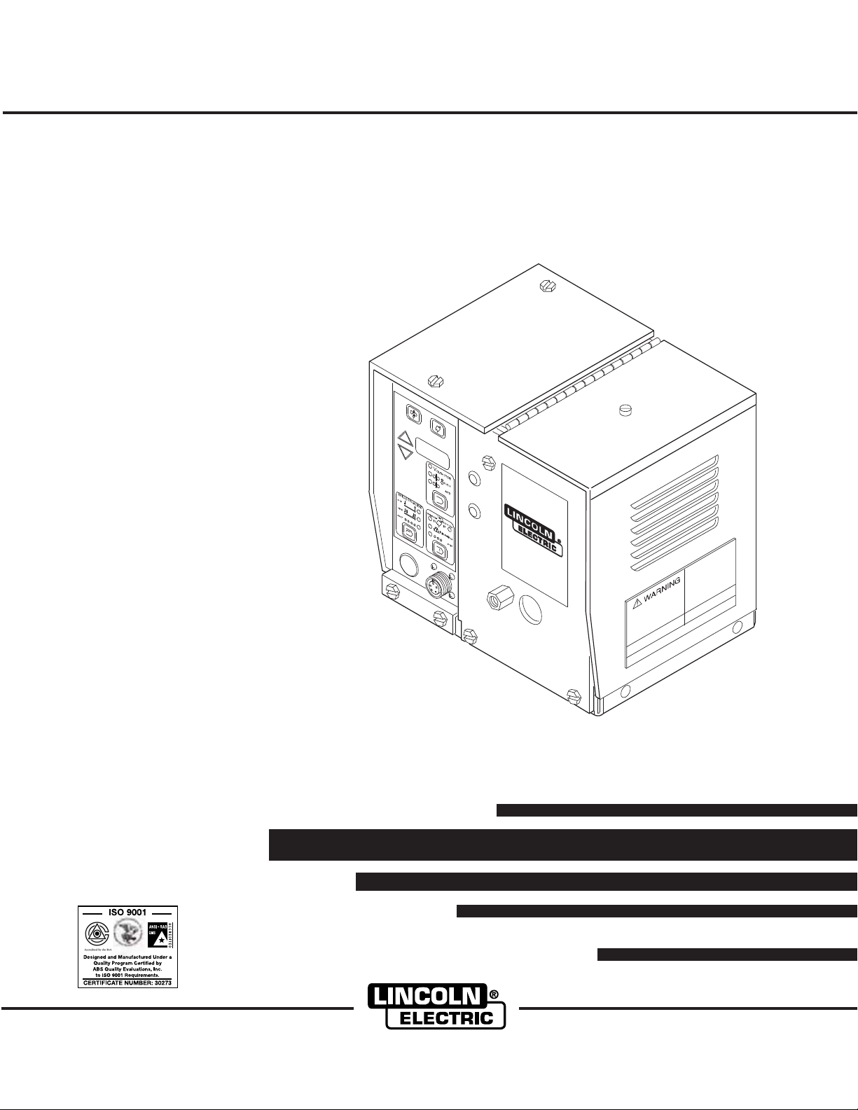
LN-742 & LN-742H Wire Feeders
For use with machines having Code Numbers:
Safety Depends on You
Lincoln arc welding and cutting
equipment is designed and built
with safety in mind. However, your
overall safety can be increased by
proper installation ... and thoughtful operation on your part. DO
NOT INSTALL, OPERATE OR
REPAIR THIS EQUIPMENT
WITHOUT READING THIS
MANUAL AND THE SAFETY
PRECAUTIONS CONTAINED
THROUGHOUT. And, most
importantly, think before you act
and be careful.
August, 2005
10027
10028
10048
10049
10238
10239
10240
10241
OPERATOR’S MANUAL
Copyright © 2005 Lincoln Global Inc.
• World's Leader in Welding and Cutting Products •
• Sales and Service through Subsidiaries and Distributors Worldwide •
Cleveland, Ohio 44117-1199 U.S.A. TEL: 216.481.8100 FAX: 216.486.1751 WEB SITE: www.lincolnelectric.com
Page 2
i
SAFETY
i
WARNING
CALIFORNIA PROPOSITION 65 WARNINGS
Diesel engine exhaust and some of its constituents
are known to the State of California to cause cancer, birth defects, and other reproductive harm.
The Above For Diesel Engines
ARC WELDING CAN BE HAZARDOUS. PROTECT YOURSELF AND OTHERS FROM POSSIBLE SERIOUS INJURY OR DEATH.
KEEP CHILDREN AWAY. PACEMAKER WEARERS SHOULD CONSULT WITH THEIR DOCTOR BEFORE OPERATING.
Read and understand the following safety highlights. For additional safety information, it is strongly recommended that you
purchase a copy of “Safety in Welding & Cutting - ANSI Standard Z49.1” from the American Welding Society, P.O. Box
351040, Miami, Florida 33135 or CSA Standard W117.2-1974. A Free copy of “Arc Welding Safety” booklet E205 is available
from the Lincoln Electric Company, 22801 St. Clair Avenue, Cleveland, Ohio 44117-1199.
BE SURE THAT ALL INSTALLATION, OPERATION, MAINTENANCE AND REPAIR PROCEDURES ARE
PERFORMED ONLY BY QUALIFIED INDIVIDUALS.
The engine exhaust from this product contains
chemicals known to the State of California to cause
cancer, birth defects, or other reproductive harm.
The Above For Gasoline Engines
FOR ENGINE
powered equipment.
1.a. Turn the engine off before troubleshooting and maintenance
work unless the maintenance work requires it to be running.
____________________________________________________
1.b.Operate engines in open, well-ventilated
areas or vent the engine exhaust fumes
outdoors.
____________________________________________________
1.c. Do not add the fuel near an open flame
welding arc or when the engine is running.
Stop the engine and allow it to cool before
refueling to prevent spilled fuel from vaporizing on contact with hot engine parts and
igniting. Do not spill fuel when filling tank. If
fuel is spilled, wipe it up and do not start
engine until fumes have been eliminated.
____________________________________________________
1.d. Keep all equipment safety guards, covers
and devices in position and in good
repair.Keep hands, hair, clothing and tools
away from V-belts, gears, fans and all other
moving parts when starting, operating or
repairing equipment.
____________________________________________________
1.e. In some cases it may be necessary to remove safety
guards to perform required maintenance. Remove
guards only when necessary and replace them when the
maintenance requiring their removal is complete.
Always use the greatest care when working near moving
parts.
___________________________________________________
1.f. Do not put your hands near the engine fan. Do not attempt
to override the governor or idler by pushing on the throttle
control rods while the engine is running.
___________________________________________________
1.g. To prevent accidentally starting gasoline engines while
turning the engine or welding generator during maintenance
work, disconnect the spark plug wires, distributor cap or
magneto wire as appropriate.
1.h. To avoid scalding, do not remove the
radiator pressure cap when the engine is
hot.
ELECTRIC AND
MAGNETIC FIELDS
may be dangerous
2.a. Electric current flowing through any conductor causes
localized Electric and Magnetic Fields (EMF). Welding
current creates EMF fields around welding cables and
welding machines
2.b. EMF fields may interfere with some pacemakers, and
welders having a pacemaker should consult their physician
before welding.
2.c. Exposure to EMF fields in welding may have other health
effects which are now not known.
2.d. All welders should use the following procedures in order to
minimize exposure to EMF fields from the welding circuit:
2.d.1.
Route the electrode and work cables together - Secure
them with tape when possible.
2.d.2. Never coil the electrode lead around your body.
2.d.3. Do not place your body between the electrode and
work cables. If the electrode cable is on your right
side, the work cable should also be on your right side.
2.d.4. Connect the work cable to the workpiece as close as
possible to the area being welded.
2.d.5. Do not work next to welding power source.
Mar ‘95
Page 3
ii
SAFETY
ii
ELECTRIC SHOCK can
kill.
3.a. The electrode and work (or ground) circuits
are electrically “hot” when the welder is on.
Do not touch these “hot” parts with your bare
skin or wet clothing. Wear dry, hole-free
gloves to insulate hands.
3.b. Insulate yourself from work and ground using dry insulation.
Make certain the insulation is large enough to cover your full
area of physical contact with work and ground.
In addition to the normal safety precautions, if welding
must be performed under electrically hazardous
conditions (in damp locations or while wearing wet
clothing; on metal structures such as floors, gratings or
scaffolds; when in cramped positions such as sitting,
kneeling or lying, if there is a high risk of unavoidable or
accidental contact with the workpiece or ground) use
the following equipment:
• Semiautomatic DC Constant Voltage (Wire) Welder.
• DC Manual (Stick) Welder.
• AC Welder with Reduced Voltage Control.
3.c. In semiautomatic or automatic wire welding, the electrode,
electrode reel, welding head, nozzle or semiautomatic
welding gun are also electrically “hot”.
3.d. Always be sure the work cable makes a good electrical
connection with the metal being welded. The connection
should be as close as possible to the area being welded.
3.e. Ground the work or metal to be welded to a good electrical
(earth) ground.
ARC RAYS can burn.
4.a. Use a shield with the proper filter and cover
plates to protect your eyes from sparks and
the rays of the arc when welding or observing
open arc welding. Headshield and filter lens
should conform to ANSI Z87. I standards.
4.b. Use suitable clothing made from durable flame-resistant
material to protect your skin and that of your helpers from
the arc rays.
4.c. Protect other nearby personnel with suitable, non-flammable
screening and/or warn them not to watch the arc nor expose
themselves to the arc rays or to hot spatter or metal.
FUMES AND GASES
can be dangerous.
5.a. Welding may produce fumes and gases
hazardous to health. Avoid breathing these
fumes and gases.When welding, keep
your head out of the fume. Use enough
ventilation and/or exhaust at the arc to keep
fumes and gases away from the breathing zone. When
welding with electrodes which require special
ventilation such as stainless or hard facing (see
instructions on container or MSDS) or on lead or
cadmium plated steel and other metals or coatings
which produce highly toxic fumes, keep exposure as
low as possible and below Threshold Limit Values (TLV)
using local exhaust or mechanical ventilation. In
confined spaces or in some circumstances, outdoors, a
respirator may be required. Additional precautions are
also required when welding on galvanized steel.
3.f.
Maintain the electrode holder, work clamp, welding cable and
welding machine in good, safe operating condition. Replace
damaged insulation.
3.g. Never dip the electrode in water for cooling.
3.h. Never simultaneously touch electrically “hot” parts of
electrode holders connected to two welders because voltage
between the two can be the total of the open circuit voltage
of both welders.
3.i. When working above floor level, use a safety belt to protect
yourself from a fall should you get a shock.
3.j. Also see Items 6.c. and 8.
5.b.
Do not weld in locations near chlorinated hydrocarbon
coming from degreasing, cleaning or spraying operations.
The heat and rays of the arc can react with solvent vapors
form phosgene, a highly toxic gas, and other irritating
products.
5.c. Shielding gases used for arc welding can displace air and
cause injury or death. Always use enough ventilation,
especially in confined areas, to insure breathing air is safe.
5.d. Read and understand the manufacturer’s instructions for this
equipment and the consumables to be used, including the
material safety data sheet (MSDS) and follow your
employer’s safety practices. MSDS forms are available from
your welding distributor or from the manufacturer.
5.e. Also see item 1.b.
Mar ‘95
vapors
to
Page 4
iii
SAFETY
iii
WELDING SPARKS can
cause fire or explosion.
6.a.
Remove fire hazards from the welding area.
If this is not possible, cover them to prevent
the welding sparks from starting a fire.
materials from welding can easily go through small cracks
and openings to adjacent areas. Avoid welding near
hydraulic lines. Have a fire extinguisher readily available.
6.b. Where compressed gases are to be used at the job site,
special precautions should be used to prevent hazardous
situations. Refer to “Safety in Welding and Cutting” (ANSI
Standard Z49.1) and the operating information for the
equipment being used.
6.c. When not welding, make certain no part of the electrode
circuit is touching the work or ground. Accidental contact
can cause overheating and create a fire hazard.
6.d. Do not heat, cut or weld tanks, drums or containers until the
proper steps have been taken to insure that such procedures
will not cause flammable or toxic vapors from substances
inside. They can cause an explosion even
been “cleaned”. For information, purchase “Recommended
Safe Practices for the
Containers and Piping That Have Held Hazardous
Substances”, AWS F4.1 from the American Welding Society
(see address above).
6.e. Vent hollow castings or containers before heating, cutting or
welding. They may explode.
Sparks and spatter are thrown from the welding arc. Wear oil
6.f.
free protective garments such as leather gloves, heavy shirt,
cuffless trousers, high shoes and a cap over your hair. Wear
ear plugs when welding out of position or in confined places.
Always wear safety glasses with side shields when in a
welding area.
6.g. Connect the work cable to the work as close to the welding
area as practical. Work cables connected to the building
framework or other locations away from the welding area
increase the possibility of the welding current passing
through lifting chains, crane cables or other alternate circuits. This can create fire hazards or overheat lifting chains
or cables until they fail.
6.h. Also see item 1.c.
Remember that welding sparks and hot
though
they have
Preparation
for Welding and Cutting of
CYLINDER may explode
if damaged.
7.a. Use only compressed gas cylinders
containing the correct shielding gas for the
process used and properly operating
regulators designed for the gas and
pressure used. All hoses, fittings, etc. should be suitable for
the application and maintained in good condition.
7.b. Always keep cylinders in an upright position securely
chained to an undercarriage or fixed support.
7.c. Cylinders should be located:
• Away from areas where they may be struck or subjected to
physical damage.
• A safe distance from arc welding or cutting operations and
any other source of heat, sparks, or flame.
7.d. Never allow the electrode, electrode holder or any other
electrically “hot” parts to touch a cylinder.
7.e. Keep your head and face away from the cylinder valve outlet
when opening the cylinder valve.
7.f. Valve protection caps should always be in place and hand
tight except when the cylinder is in use or connected for
use.
7.g. Read and follow the instructions on compressed gas
cylinders, associated equipment, and CGA publication P-l,
“Precautions for Safe Handling of Compressed Gases in
Cylinders,” available from the Compressed Gas Association
1235 Jefferson Davis Highway, Arlington, VA 22202.
FOR ELECTRICALLY
powered equipment.
8.a. Turn off input power using the disconnect
switch at the fuse box before working on
the equipment.
8.b. Install equipment in accordance with the U.S. National
Electrical Code, all local codes and the manufacturer’s
recommendations.
8.c. Ground the equipment in accordance with the U.S. National
Electrical Code and the manufacturer’s recommendations.
Mar ‘95
Page 5
iv
SAFETY
iv
PRÉCAUTIONS DE SÛRETÉ
Pour votre propre protection lire et observer toutes les instructions
et les précautions de sûreté specifiques qui parraissent dans ce
manuel aussi bien que les précautions de sûreté générales suivantes:
Sûreté Pour Soudage A L’Arc
1. Protegez-vous contre la secousse électrique:
a. Les circuits à l’électrode et à la piéce sont sous tension
quand la machine à souder est en marche. Eviter toujours
tout contact entre les parties sous tension et la peau nue
ou les vétements mouillés. Porter des gants secs et sans
trous pour isoler les mains.
b. Faire trés attention de bien s’isoler de la masse quand on
soude dans des endroits humides, ou sur un plancher
metallique ou des grilles metalliques, principalement dans
les positions assis ou couché pour lesquelles une grande
partie du corps peut être en contact avec la masse.
c. Maintenir le porte-électrode, la pince de masse, le câble
de soudage et la machine à souder en bon et sûr état
defonctionnement.
d.Ne jamais plonger le porte-électrode dans l’eau pour le
refroidir.
e. Ne jamais toucher simultanément les parties sous tension
des porte-électrodes connectés à deux machines à souder
parce que la tension entre les deux pinces peut être le
total de la tension à vide des deux machines.
f. Si on utilise la machine à souder comme une source de
courant pour soudage semi-automatique, ces precautions
pour le porte-électrode s’applicuent aussi au pistolet de
soudage.
2. Dans le cas de travail au dessus du niveau du sol, se protéger
contre les chutes dans le cas ou on recoit un choc. Ne jamais
enrouler le câble-électrode autour de n’importe quelle partie
du corps.
5. Toujours porter des lunettes de sécurité dans la zone de
soudage. Utiliser des lunettes avec écrans lateraux dans les
zones où l’on pique le laitier.
6. Eloigner les matériaux inflammables ou les recouvrir afin de
prévenir tout risque d’incendie dû aux étincelles.
7. Quand on ne soude pas, poser la pince à une endroit isolé de
la masse. Un court-circuit accidental peut provoquer un
échauffement et un risque d’incendie.
8. S’assurer que la masse est connectée le plus prés possible
de la zone de travail qu’il est pratique de le faire. Si on place
la masse sur la charpente de la construction ou d’autres
endroits éloignés de la zone de travail, on augmente le risque
de voir passer le courant de soudage par les chaines de levage, câbles de grue, ou autres circuits. Cela peut provoquer
des risques d’incendie ou d’echauffement des chaines et des
câbles jusqu’à ce qu’ils se rompent.
9. Assurer une ventilation suffisante dans la zone de soudage.
Ceci est particuliérement important pour le soudage de tôles
galvanisées plombées, ou cadmiées ou tout autre métal qui
produit des fumeés toxiques.
10. Ne pas souder en présence de vapeurs de chlore provenant
d’opérations de dégraissage, nettoyage ou pistolage. La
chaleur ou les rayons de l’arc peuvent réagir avec les vapeurs
du solvant pour produire du phosgéne (gas fortement toxique)
ou autres produits irritants.
11. Pour obtenir de plus amples renseignements sur la sûreté,
voir le code “Code for safety in welding and cutting” CSA
Standard W 117.2-1974.
PRÉCAUTIONS DE SÛRETÉ POUR
3. Un coup d’arc peut être plus sévère qu’un coup de soliel,
donc:
a. Utiliser un bon masque avec un verre filtrant approprié
ainsi qu’un verre blanc afin de se protéger les yeux du rayonnement de l’arc et des projections quand on soude ou
quand on regarde l’arc.
b. Porter des vêtements convenables afin de protéger la
peau de soudeur et des aides contre le rayonnement de
l‘arc.
c. Protéger l’autre personnel travaillant à proximité au
soudage à l’aide d’écrans appropriés et non-inflammables.
4. Des gouttes de laitier en fusion sont émises de l’arc de
soudage. Se protéger avec des vêtements de protection libres
de l’huile, tels que les gants en cuir, chemise épaisse, pantalons sans revers, et chaussures montantes.
LES MACHINES À SOUDER À
TRANSFORMATEUR ET À
REDRESSEUR
1. Relier à la terre le chassis du poste conformement au code de
l’électricité et aux recommendations du fabricant. Le dispositif
de montage ou la piece à souder doit être branché à une
bonne mise à la terre.
2. Autant que possible, I’installation et l’entretien du poste seront
effectués par un électricien qualifié.
3. Avant de faires des travaux à l’interieur de poste, la debrancher à l’interrupteur à la boite de fusibles.
4. Garder tous les couvercles et dispositifs de sûreté à leur
place.
Mar. ‘93
Page 6
for selecting a QUALITY product by Lincoln Electric. We want you
Thank You
to take pride in operating this Lincoln Electric Company product
••• as much pride as we have in bringing this product to you!
Please Examine Carton and Equipment For Damage Immediately
When this equipment is shipped, title passes to the purchaser upon receipt by the carrier. Consequently, Claims
for material damaged in shipment must be made by the purchaser against the transportation company at the
time the shipment is received.
Please record your equipment identification information below for future reference. This information can be
found on your machine nameplate.
Product _________________________________________________________________________________
Model Number ___________________________________________________________________________
Code Number or Date Code_________________________________________________________________
Serial Number____________________________________________________________________________
Date Purchased___________________________________________________________________________
vv
Where Purchased_________________________________________________________________________
Whenever you request replacement parts or information on this equipment, always supply the information you
have recorded above. The code number is especially important when identifying the correct replacement parts.
On-Line Product Registration
- Register your machine with Lincoln Electric either via fax or over the Internet.
• For faxing: Complete the form on the back of the warranty statement included in the literature packet
accompanying this machine and fax the form per the instructions printed on it.
• For On-Line Registration: Go to our
“Product Registration”. Please complete the form and submit your registration.
Read this Operators Manual completely before attempting to use this equipment. Save this manual and keep it
handy for quick reference. Pay particular attention to the safety instructions we have provided for your protection.
The level of seriousness to be applied to each is explained below:
WEB SITE at www.lincolnelectric.com. Choose “Quick Links” and then
WARNING
This statement appears where the information must be followed exactly to avoid serious personal injury or
loss of life.
CAUTION
This statement appears where the information must be followed to avoid minor personal injury or damage to
this equipment.
Page 7

vi
TABLE OF CONTENTS
Page
Safety . . . . . . . . . . . . . . . . . . . . . . . . . . . . . . . . . . . . . . . . . . . . . . . . . . . . . . . i-iv
Installation . . . . . . . . . . . . . . . . . . . . . . . . . . . . . . . . . . . . . . . . . . . . . . . . . . . Section A
Technical Specifications - LN-742 . . . . . . . . . . . . . . . . . . . . . . . . . . . . . . A-1
Mounting Location . . . . . . . . . . . . . . . . . . . . . . . . . . . . . . . . . . . . . . . . . . A-2
Input Cable Connections . . . . . . . . . . . . . . . . . . . . . . . . . . . . . . . . . . . . . A-2
Work Cable . . . . . . . . . . . . . . . . . . . . . . . . . . . . . . . . . . . . . . . . . . . . . . . . A-5
Gun and Cable Assemblies . . . . . . . . . . . . . . . . . . . . . . . . . . . . . . . . . . . A-5
Gun Cable Connections . . . . . . . . . . . . . . . . . . . . . . . . . . . . . . . . . . . . . . A-5
Water Connections (For Water Cooled Guns) . . . . . . . . . . . . . . . . . . . . . A-6
GMAW Shielding Gas Hookup . . . . . . . . . . . . . . . . . . . . . . . . . . . . . . . . . A-7
Operation . . . . . . . . . . . . . . . . . . . . . . . . . . . . . . . . . . . . . . . . . . . . . . . . . . . . Section B
Operating Instructions . . . . . . . . . . . . . . . . . . . . . . . . . . . . . . . . . . . . . . . B-1
Safety Precautions . . . . . . . . . . . . . . . . . . . . . . . . . . . . . . . . . . . . . . . . . . B-1
General Description . . . . . . . . . . . . . . . . . . . . . . . . . . . . . . . . . . . . . . . . . B-1
Recommended Processes and Equipment . . . . . . . . . . . . . . . . . . . . . . . B-1
Controls and Settings . . . . . . . . . . . . . . . . . . . . . . . . . . . . . . . . . . . . . . . . B-2
Acceleration Setting . . . . . . . . . . . . . . . . . . . . . . . . . . . . . . . . . . . . . . . . . B-3
English or Metric Speed Display Units . . . . . . . . . . . . . . . . . . . . . . . . . . . B-3
Circuit Protection . . . . . . . . . . . . . . . . . . . . . . . . . . . . . . . . . . . . . . . . . . . B-3
Drive Roll Installation . . . . . . . . . . . . . . . . . . . . . . . . . . . . . . . . . . . . . . . . B-3
Idle Roll Pressure Setting . . . . . . . . . . . . . . . . . . . . . . . . . . . . . . . . . . . . . B-7
Wire Loading . . . . . . . . . . . . . . . . . . . . . . . . . . . . . . . . . . . . . . . . . . . . . . B-8
Making a Weld . . . . . . . . . . . . . . . . . . . . . . . . . . . . . . . . . . . . . . . . . . . . . B-12
Wire Reel Changing . . . . . . . . . . . . . . . . . . . . . . . . . . . . . . . . . . . . . . . . . B-12
vi
Accessories . . . . . . . . . . . . . . . . . . . . . . . . . . . . . . . . . . . . . . . . . . . . . . . . . . Section C
General . . . . . . . . . . . . . . . . . . . . . . . . . . . . . . . . . . . . . . . . . . . . . . . . . . . C-1
Flux System Components . . . . . . . . . . . . . . . . . . . . . . . . . . . . . . . . . . . . C-2
Power Input Cables . . . . . . . . . . . . . . . . . . . . . . . . . . . . . . . . . . . . . . . . . C-3
Welding Guns . . . . . . . . . . . . . . . . . . . . . . . . . . . . . . . . . . . . . . . . . . . . . . C-3
Spindles, Stands, and Adapters . . . . . . . . . . . . . . . . . . . . . . . . . . . . . . . . C-4
Attaching the Wire Reel Stand . . . . . . . . . . . . . . . . . . . . . . . . . . . . . . . . . C-5
Drive Roll Kits . . . . . . . . . . . . . . . . . . . . . . . . . . . . . . . . . . . . . . . . . . . . . . C-6
Maintenance . . . . . . . . . . . . . . . . . . . . . . . . . . . . . . . . . . . . . . . . . . . . . . . . . Section D
Routine Maintenance . . . . . . . . . . . . . . . . . . . . . . . . . . . . . . . . . . . . . . . . D-1
Periodic Maintenance . . . . . . . . . . . . . . . . . . . . . . . . . . . . . . . . . . . . . . . . D-1
Troubleshooting and Repair . . . . . . . . . . . . . . . . . . . . . . . . . . . . . . . . . . . . Section E
How To Use Troubleshooting Guide . . . . . . . . . . . . . . . . . . . . . . . . . . . . E-1
Troubleshooting Guide . . . . . . . . . . . . . . . . . . . . . . . . . . . . . . . . . . . . . . . E-2
Electrical Diagram . . . . . . . . . . . . . . . . . . . . . . . . . . . . . . . . . . . . . . . . . . . . . Section F
Parts Manual . . . . . . . . . . . . . . . . . . . . . . . . . . . . . . . . . . . . . . . . . . . . . . . . . P-228
LN-742 & LN-742H
Page 8
A-1
INSTALLATION
TECHNICAL SPECIFICATIONS – LN-742
INPUT VOLTAGE
40 to 42V ±10%, 50/60 Hz, 4.0 Amps
WIRE FEED SPEED
A-1
SYSTEM
LN-742
LN-742H
SYSTEM
LN-742
LN-742H
LN-742
LN-742H
OPERATING
STORAGE
BOTH LN-742 AND LN-742H
2 ROLL FEEDER
WITHOUT WIRE STAND
WIRE SPEED RANGE
50 in. to 770 in. per minute (1.25 to 19.5 m/min)
80 in. to 1200 in. per minute (2.00 to 30.5 m/min)
WIRE DIAMETERS
ELECTRODE
SOLID
SOLID
CORED
CORED
0.025 in. through 1/16 in. (0.6 through 1.6 mm)
0.025 in. through 0.045 in. (0.6 through 1.2 mm)
0.045 in. through 3/32 in. (1.2 through 2.4 mm)
DIAMETER
0.035 in. (0.9 mm)
TEMPERATURE RATING (ALL MODELS)
-4˚F to 104˚F (-20˚C to +40˚C)
-40˚F to 104˚F (-40˚C to +40˚C)
PHYSICAL DIMENSIONS
LENGTH
9.62 in.
(244 mm)
WIDTH
9.76 in.
(247 mm)
HEIGHT
10.89 in.
(277 mm)
TOTAL WEIGHT
LESS ELECTRODE
24 lbs
(11.0 kg)
2 ROLL FEEDER
WITH WIRE STAND (K377)
4 ROLL FEEDER
WITHOUT WIRE STAND
4 ROLL FEEDER
WITH WIRE STAND (K377)
ENVIRONMENTAL RATING (ALL MODELS)
20.68 in.
(525 mm)
10.60 in.
(269 mm)
21.66 in.
(550 mm)
IP21 (IEC 529)
LN-742 & LN-742H
9.76 in.
(247 mm)
11.60 in.
(295 mm)
11.60 in.
(295 mm)
17.00 in.
(432 mm)
11.11 in.
(282 mm)
17.00 in.
(432 mm)
34 lbs
(15.5 kg)
28.7 lbs
(13.1 kg)
38.7 lbs
(17.7 kg)
Page 9
A-2
NUT
STUD
ELECTRODE
CONTROL
CABLE
COPPER
STRAP
MOUNTING LOCATION
INSTALLATION
A-2
The LN-742 wire feeders can be mounted directly on
top of the power source providing that it is secure and
level. The LN-742 can also be mounted to an
undercarriage when portability is required. The LN-742
should be installed upright on a horizontal surface.
A K178-1 mounting platform is available for mounting
the LN-742 to the top of Idealarc power sources. Refer
to Section C, Accessories, for details.
INPUT CABLE CONNECTIONS
Refer to Section C, Accessories, for descriptions of
the various input cable assemblies available for the
LN-742 wire feeder.
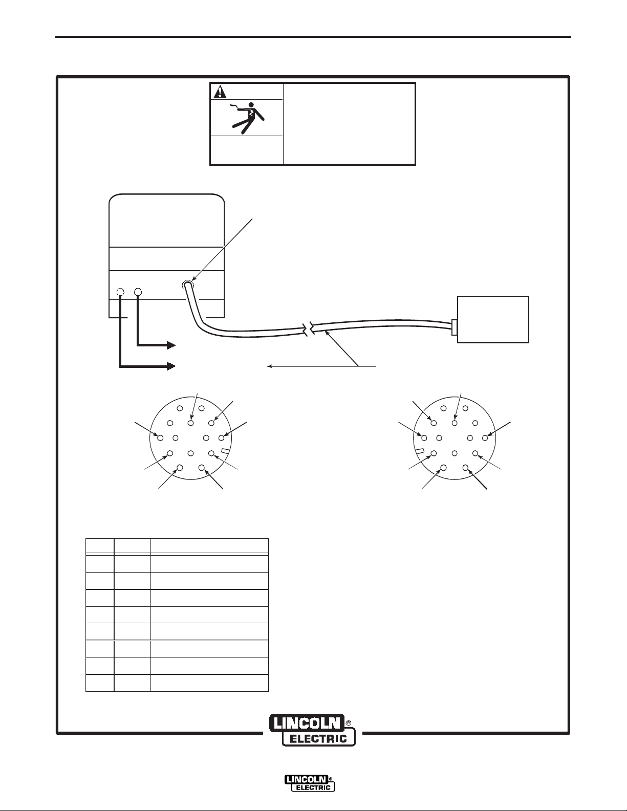
WARNING
Turn input power off before connecting the LN-742
wire feeder.
------------------------------------------------------------------------
For connecting an LN-742 to a specific Lincoln power
source, follow steps 1 through 5, and refer to the
connection diagram in Figure A.3. The welding cable
used must be sized according to the current and the
duty cycle of the application.
1. Connect the end of the control cable with the 14pin cable plug to the mating receptacle on the
power source.
2. Connect the electrode lead to the power source
output terminal of the desired polarity.
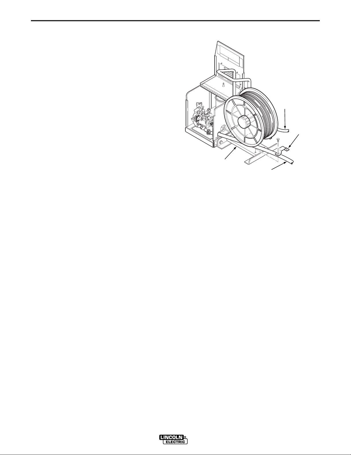
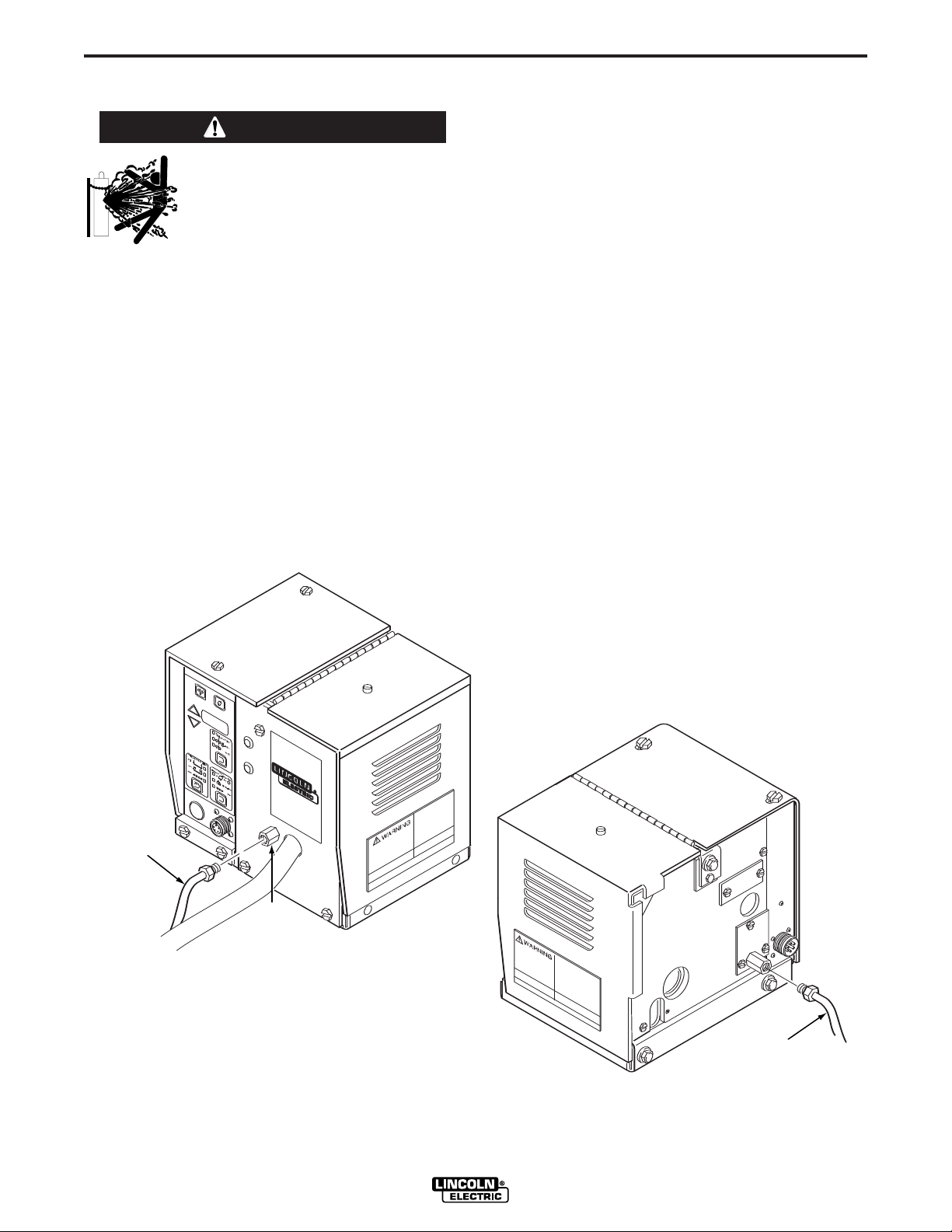
3. Referring to Figure A.1, route the other end of the
electrode cable through the large oval hole in the
rear panel of the LN-742 case. Connect the
electrode to the copper strap on the side of the
gearbox using the stud and nut provided.
FIGURE A.1 – INPUT CONTROL CABLE AND
ELECTRODE CABLE CONNECTIONS.
With input power disconnected at the source, install
the input cable per connection diagram A.3, and
complete the following instructions:
LN-742 & LN-742H
Page 10
A-3
WIRE REEL
MOUNTING
ASSEMBLY
CONTROL
CABLE
ELECTRODE
CABLE
STRAIN
RELIEF
CLAMP
INSTALLATION
A-3
4. Connect the remaining end of the control cable
with the eight-socket cable plug to the mating
receptacle on the LN-742.
5. Referring to Figure A.2, install the input cable
under the wire reel mounting stand strain relief
clamp. Remove the screws holding the clamp to
the base of wire reel mounting assembly. Put the
input cable under the clamp and reinstall the
screws.
The connection diagram, Figure A.3, shows the
electrode as positive. To change polarity, turn the
power source off. Reverse the electrode and work
cables at the power source, and set the wire feeder
voltmeter polarity switch on the power source to the
proper polarity.
Pins not listed in the table in Figure A.3 are not
connected on the cable.
If using the K589-1 remote control kit, set the power
source control switch to the “Remote” position.
FIGURE A.2 – STRAIN RELIEF CLAMP.
LN-742 & LN-742H
Page 11
A-4
ELECTRIC
SHOCK
CAN KILL
TURN INPUT POWER OFF
BEFORE CONNECTING THE
LN-742 WIRE FEEDER.
WARNING
CLEVELAND, OHIO U.S.A
-
+
LINCOLN
POWER SOURCE
LN-742
WIRE FEEDER
LN-742
INPUT CABLE
ASSEMBLY
TO WORK
ELECTRODE CABLE
14-SOCKET BOX RECEPTACLE, FRONT VIEW
AND 14-PIN CABLE PLUG, REAR VIEW
FUNCTIONS ARE LISTED FOR REFERENCE
ONLY AND EACH MAY OR MAY NOT BE
PRESENT IN YOUR EQUIPMENT.
14-SOCKET BOX RECEPTACLE, REAR VIEW
AND 14-PIN CABLE PLUG, FRONT VIEW
14 PIN
AMPHENOL
K=42
K=42
I=41 I=41
H=21 H=21C=2 C=2
G=75 G=75D=4 D=4
F=76
PIN
C
2 TRIGGER CIRCUIT
TRIGGER CIRCUIT
OUTPUT CONTROL
OUTPUT CONTROL
OUTPUT CONTROL
WORK
42V AC
42V AC
4
77
76
75
21
41
42
LEAD FUNCTION
F=76E=77 E=77
D
E
F
G
H
I
K
INSTALLATION
FIGURE A.3 – LN-742 WIRE FEEDER TO LINCOLN POWER SOURCE – CONNECTION DIAGRAM.
A-4
LN-742 & LN-742H
Page 12
A-5
AMPHENOL
PLUG
GUN CABLE
ASSEMBLY
CONDUCTOR
BLOCK
LOCKING
KNOB
INSTALLATION
A-5
WORK CABLE
Connect a work lead of sufficient size and length
(Table A.1) between the proper output stud on the
power source and the work. Be sure the connection to
the work makes tight metal-to-metal electrical contact.
TABLE A.1 – WORK LEAD SPECIFICATIONS
Copper Work Cable Size, AWG
Current 60% Up To 50 Ft 50 Ft-100 Ft
2
Duty Cycle (15.2 m
300 Amps 0 (53 mm
400 Amps 00 (67 mm
500 Amps 00 (67 mm2) 000 (85 mm2)
600 Amps 000 (85 mm2) 0000 (107 mm2)
) (15.2-30.4 m2)
2
) 00 (67 mm2)
2
) 000 (85 mm2)
GUN AND CABLE ASSEMBLIES
The LN-742 can be used with several guns. In most
cases, Lincoln guns and cables are shipped
assembled, ready to weld. Use the gun and cable
assembly for the electrode type (solid, Outershield , or
Innershield) and electrode size to be used. Refer to
Section C, Accessories, for different gun types.
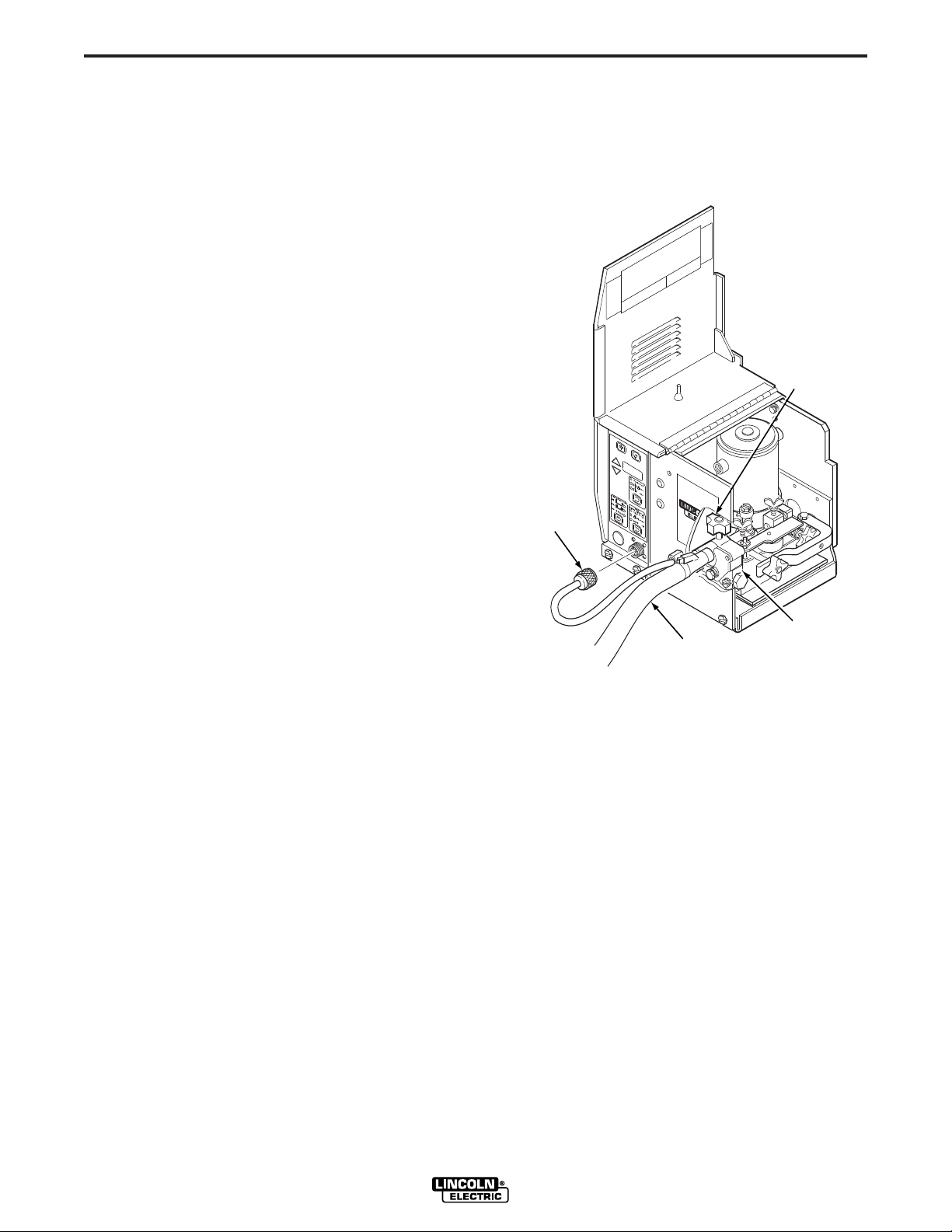
Connect the control cable amphenol plug into the
mating 5-cavity receptacle on the front of the control
section below the keypad.
FIGURE A.4 – GUN CABLE CONNECTIONS.
GUN CABLE CONNECTIONS
Lay the cable out straight. Insert the connector on the
welding conductor cable through the large hole in the
front panel of the LN-742 and into the brass conductor
block on the front of the gearbox. Refer to Figure A.4.
Make sure it is all the way in and tighten the locking
knob. Keep this connection clean and bright.
LN-742 & LN-742H
Page 13
A-6
INSTALLATION
A-6
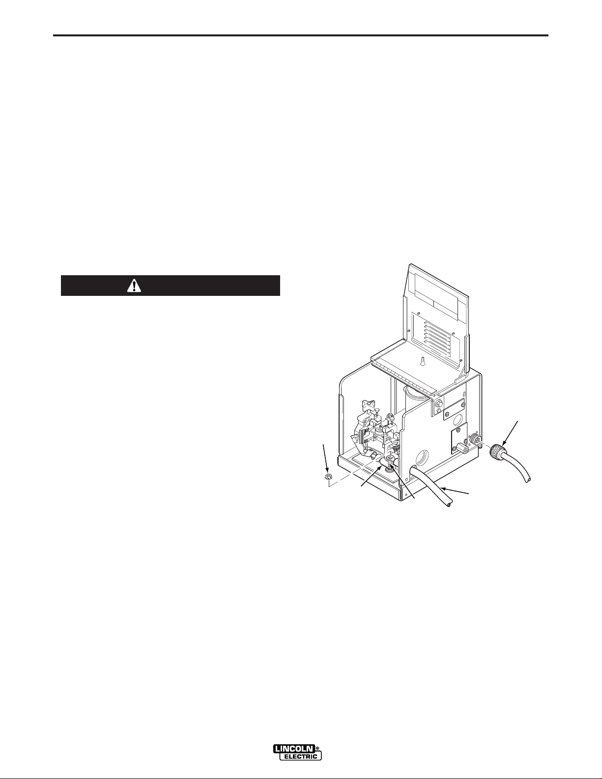
WATER CONNECTIONS
(FOR WATER COOLED GUNS)
The LN-742 must have a K590-1 Water Solenoid Kit
installed (see Section C, Accessories). Refer to
Figure A.5 and perform the following steps:
The maximum water pressure permitted for use with
the LN-742 is 55 psi (3.8 bar).
NOTE: If not using a Lincoln water cooler, and if your
water cooling device is not designed for use with a
waterline solenoid valve, you may remove the solenoid
and screw the male fitting (after applying sealant)
directly into the brass manifold block.
FIGURE A.5 – WATER CONNECTIONS.
1. Using male 5/8-18 UNF left-hand thread fittings,
connect appropriate water hoses to the coolant
inlet and outlet on the back of the LN-742.
Connect the other ends of these hoses to the
appropriate ports on your water cooling units.
2. In the event the water line fittings on your water
cooled gun are incompatible with the female quick
connects on the front of the LN-742, male quick
connects are provided for installation on 3/16 in.
I.D. hose (customer to provide appropriate
clamps). The feeder connectors self seal when
disconnected.
LN-742 & LN-742H
Page 14
A-7
t
t
GAS
SUPPLY
HOSE
GAS
INERT
GAS
FITTING
INSTALLATION
A-7
GMAW SHIELDING GAS HOOKUP
WARNING
Gas under pressure is explosive.
Always keep gas cylinders in an
upright position and chained to the
undercarriage or a stationary
support. See American National
Standard Z-49.1, “Safety In Welding
And Cutting”, published by the
American Welding Society.
------------------------------------------------------------------------
Customer must provide a cylinder of shielding gas, a
pressure regulator, a flow control valve, and a hose
from the flow valve to the gas inlet fitting of the LN-742.
Install per Figure A.6 and the following:
1. Connect the supply hose from the gas cylinder
flow valve outlet to the 5/8-18 female inert gas
fitting on the back panel of the LN-742.
2. Install the barbed fitting and union nut to the
5/8-18 female inert gas fitting on the front of the
LN-742. Connect 3/16 in. (4.8 mm) I.D. gas hose
from the gun to the barbed fitting.
When the gun is to be removed, this fitting can be
easily detached by loosening the union nut.
The LN-742 can be used with any shielding gas
recommended in the electrode’s product literature at a
maximum pressure of 60 psi (4.1 bar). This may
include gasses such as Argon, Helium and Nitrogen
and blended gases such as Ar-He, Ar-N2, Ar-O2,Ar-
CO2, CO2, AR-CO2,-O2.
FIGURE A.6 – SHIELDING GAS HOOKUP.
LN-742 & LN-742H
Page 15
B-1
OPERATION
B-1
OPERATING INSTRUCTIONS
Read and understand the entire Operation Section
prior to operating the machine.
SAFETY PRECAUTIONS
WARNING
ELECTRIC SHOCK
can kill.
• Do not touch electrically live parts
or electrode with skin or wet
clothing.
• Insulate yourself from work or
ground.
• Always wear dry insulating
gloves.
GENERAL DESCRIPTION
The K617 LN-742 semiautomatic constant speed wire
feeder is specifically equipped for gas metal arc
welding using flux-cored Outershield electrodes and
solid wire. The LN-742 is also suitable for self-shielded
flux-cored Innershield electrodes, submerged arc
welding (if constant voltage is satisfactory), and other
open arc welding. It has been factory assembled with
the following features:
• Wire feed control [50 to 770 in./min (1.25 to 19.5
m/min) for the LN-742; 80 to 1200 in./min (2.00 to
30.5 m/min) for the LN-742H].
• Factory installed gas solenoid valve and gas
fittings.
• Wire drive uses a permanent magnet motor and
includes tool-less “quick-release” idle roll pressure
arm, outgoing guide tube and gun cable fastening.
• Optional factory installed water solenoid and fittings
for use with water cooled welding guns.
FUMES AND GASES
can be dangerous.
• Keep your head out of fumes.
• Use ventilation or exhaust to
remove fumes from breathing
zone.
WELDING SPARKS
can cause fire or explosion.
• Keep flammable material away.
• Do not weld on containers that
have held combustibles.
ARC RAYS
can burn.
• Wear eye, ear, and body
protection.
Observe additional Safety Guidelines detailed in
the beginning of this manual.
The LN-742 4-Roll is designed to provide the additional
feeding force required when using gun cables over 15
ft (4.6 m) long or when the wire is pulled long distances
(such as when bulk packages are used). Because the
four-roll feeder has twice the contact surface, it can
also help when feeding softer wires by delivering the
same or more feeding force as the two-roll with less
overall wire deformation.
RECOMMENDED PROCESSES AND
EQUIPMENT
The LN-742 is recommended for use in MIG and
Innershield welding applications with constant voltage
power sources with 42 VAC auxiliary power and a 14pin connector receptacle, such as the Invertec V300PRO, V350-PRO, DC-400, DC-600, DC-655 DC-650PRO, or Lincoln CV type power sources.
The LN-742 is capable of the following wire feed
ranges:
• 0.025 to 1/16 in. (0.6 to 1.6 mm) solid wire for gasmetal-arc or CV submerged arc processes.
• 0.045 to 3/32 in. (1.2 to 2.4 mm) cored wire for
Outershield gas-metal-arc processes.
LN-742 & LN-742H
Page 16

B-2
COLD INCH
OLTMETER
INCH
WFS
PREFLOW POSTFLOW
BURNBACK
SPOT
STD
LOCK
SPOT
TIMETRIGGER MODE
t1
t2
GAS PURGE
t
t
t
GAS
PURGE
KEY
LED
DISPLAY
FUNCTION
SELECTION
CONTROLS
TIMER
SELECTION
CONTROLS
SETTING
ADJUSTMENT
ARROW KEYS
TRIGGER
MODE
CONTROLS
COLD
INCH
KEY
OPERATION
B-2
• 0.045 to 5/64 in. (1.2 to 2.0 mm) cored wire for
Innershield processes.
The LN-742H is capable of the following wire feed
ranges:
• 0.025 to 0.045 in. (0.6 to 1.2 mm) solid wire for gasmetal-arc or CV submerged arc processes.
• 0.035 to 0.045 in. (1.2 mm) cored wire for
Outershield, Metalshield or Innershield processes.
CONTROLS AND SETTINGS
The operator controls are located on the keypad
shown in Figure B.1. The keypad consists of: 7
membrane keys with tactile-feel embossed domes,
that are generously spaced to provide easy selection,
even while wearing welding gloves; a long-life, 3-1/2
digit, 7 segment LED display with 0.56 in. (14.2 mm)
character height, permitting easy viewing even from
long gun cable distances; and high intensity, red, LED
indicator lights that allow for viewing at almost any
angle.
TRIGGER MODE CONTROLS. This control enables
the operator to choose the mode of operation as
shown by the indicator lights. Pressing the key causes
the mode lights to sequence (from top to bottom).
FIGURE B.1 – WIRE FEEDER CONTROLS.
The top light indicates standard (two-step) trigger
mode. In this mode the unit will only be active when
the trigger is pressed. The middle light indicates lock
(four-step) trigger mode. In this mode the solenoid is
energized when the trigger is pressed, the power
source and wire feeder are energized after preflow
time when the trigger is released. Closing the trigger a
second time turns off the wire feeder and then the
power source after burnback time. Releasing the
trigger a second time turns off the solenoid after
Burnback time. The bottom light indicates spot weld
trigger mode. Closing the trigger allows a single,
timed, weld cycle. The duration of the weld cycle is set
with the time selection controls. The spot on timer
starts when welding current flows.
TIME SELECTION CONTROLS. This control enables
the operator to choose which timer will be displayed
as shown by the indicator lights. Pressing the key
causes the mode lights to sequence (from top to
bottom). Any timers not available to the currently
selected mode will be skipped. Times displayed in the
LED display are adjusted using the setting adjustment
arrows to the left of the LED display. The top left light
indicates the preflow time is being displayed in
seconds. The top right indicator light indicates the
postflow time is being displayed in seconds. The
middle light indicates the burnback time is being
displayed in seconds. The bottom light indicates the
spot weld time is being displayed in seconds.
LN-742 & LN-742H
Page 17

B-3
OPERATION
B-3
FUNCTION SELECTION CONTROLS. This control
enables the operator to select the function that will be
displayed as shown by the indicator lights. Pressing
the key causes the mode lights to sequence (from top
to bottom). Settings displayed in the LED display are
adjusted using the setting adjustment arrows to the
left of the LED display. The top light indicates the arc
voltage is being displayed in volts. The middle light
indicates the inch speed is being displayed. The
bottom light indicates the weld feed speed (WFS) is
being displayed.
INCREASE ARROW. This key increases the setting
of the parameter selected to be displayed, using the
“Quick-Set” feature for fast and accurate setting.
DECREASE ARROW. This key decreases the setting
of the parameter selected to be displayed, using the
“Quick-Set” feature for fast and accurate setting.
QUICK-SET FEATURE. This feature permits the
arrow keys to control each display digit one at a time.
The display digits blink in sequence from left to right.
Pressing an arrow key immediately after a digit blinks
alters that digit. Releasing the arrow key causes the
left-to-right sequencing to resume.
COLD INCH KEY. This key energizes the wire feeder
to inch the wire forward, but does not energize the
power source or solenoid valve.
GAS PURGE KEY. This key energizes the solenoid
valve to purge any remaining gasses, but does not
energize the wire feeder or power source.
ENGLISH OR METRIC SPEED
DISPLAY UNITS
Pressing both the Gas Purge key and Timer Selection
key causes the speed display units to toggle between
inches per minute (no decimal point displayed) or
meters per minute (decimal point displayed). If the LED
display is showing the voltmeter or one of the timer
settings when these keys are pressed, the display will
change to the weld speed to indicate the selected
speed display units. See Figure B.1 for key locations.
CIRCUIT PROTECTION
The LN-742 has solid-state overload protection of the
wire drive motor. If the wire drive motor becomes
overloaded for an extended period of time, the
protection circuitry turns off the power source, wire
feeder, and solenoid, then displays the error code E30
on the LED display. This indicates the wire drive motor
is overloaded, with the number indicating the time
remaining in seconds before the unit will automatically
reset. This number continues to decrement every
second until it reaches zero. At that time the unit
resets automatically and the previous display will
return indicating that the unit is ready for operation.
Over loads can result from: improper tip size, liner,
drive rolls, or guide tubes; obstructions or bends in the
gun cable; feeding wire that is larger than the rated
capacity of the feeder; or any other factors that would
impede normal wire feeding.
ACCELERATION SETTING
Pressing both the Gas Purge key and the Function
Selection key at the same time, on the keypad shown
in Figure B.1, enables the acceleration setting display.
The LED display will indicate “A-X” with “X” being a
number from 1 (slowest) to 5 (fastest). This number is
adjusted using the setting adjustment arrow keys. To
exit the acceleration setting function, press both keys a
second time, or press any other key except for the
setting adjustment arrow keys.
LN-742 & LN-742H
DRIVE ROLL INSTALLATION
CHANGING DRIVE ROLLS FOR TWOROLL WIRE FEEDERS:
To change drive rolls on a two-roll wire feeder, refer to
Figure B.2 and perform the following steps:
1. Turn off the welding power source.
2. Rotate the latch knob on the quick release arm.
Page 18

B-4
GUIDE TUBE DETAIL
OUTGOING
GUIDE TUBE
INSERT
OUTGOING
GUIDE
TUBE
LARGE
RADIUS
DRIVE
ROLL
INCOMING
GUIDE
TUBE
SMALL
RADIUS
IDLE
ROLL
CLAMPING
COLLAR
SPACER (IF REQUIRED)
OUTPUT
SHAFT
DRIVE
ROLL
HALVES
OPERATION
FIGURE B.2 – INSTALLING DRIVE ROLLS ON A TWO-ROLL FEEDER.
B-4
LN-742 & LN-742H
Page 19

B-5
OPERATION
B-5
3. Remove the hex head screw and clamping collar.
Remove the drive roll from the shaft.
4. The new roll to be installed is stamped for the size
wire to be fed. An “A” after the size indicates
aluminum wire. Remove the rolls from the kit and
wipe them clean. Wipe the output shaft and locating
shoulder clean.
5. Use the clamping collar and hex head screw to
install the roll on the output shaft. Certain size drive
rolls consist of two roll halves, and may contain a
spacer. If the drive roll you are installing contains a
spacer, the spacer fits between the two halves of
the drive roll. Tighten the hex head screw.
6. Back out the guide tube clamping screws.
Remove the old guide tubes, if installed.
7. Insert the longer guide tube into the rear hole and
the other guide tube through the front hole. The
fine wire chisel point end of the guide tube must
have the larger radius end next to the drive roll.
See Figure B.2. Push the guide tube back as far
as it will go and tighten the clamping screw. Insert
the incoming guide tube as far back as it will go
and tighten the clamping screw. The clamping
screws are dog points. When the guide tubes are
properly installed these dog points will lock into
the annular grooves in each of the guide tubes.
8. Set the idle roll pressure as detailed in the Idle
Roll Pressure Setting procedure detailed later in
this section.
4. Loosen the thumb screws holding the guide tubes
in place. Remove the incoming and outgoing
guide tubes, if installed.
5. Remove the hex head screws and clamping
collars from the output shafts. Remove the drive
rolls and middle guide tube.
6. The new rolls to be installed are stenciled with the
wire size that will be fed. An “A” after the number
indicates aluminum wire. Remove the rolls from
the kit and wipe them clean. Wipe the output
shafts and locating shoulders clean.
7. Install one roll onto the output shaft closest to the
incoming side of the feeder clamping collar and
hex head screw. Certain size drive rolls consist of
two roll halves, and may contain a spacer. If the
drive roll you are installing contains a spacer, the
spacer fits between the two halves of the drive
roll. Tighten the hex head screw.
8. Install the middle guide tube, but do not tighten at
this time. When installing a 0.035” middle guide
tube the larger radius should be aligned towards
the drive roll. Slide the guide tube up against the
installed drive roll.
9. Install the second drive roll on the remaining shaft
the same way as the first. Center the middle guide
tube between the rolls and tighten the
thumbscrews holding it in place.
10. Close and latch both quick release levers.
CHANGING DRIVE ROLLS FOR FOURROLL WIRE FEEDERS:
To change drive rolls on a four-roll wire feeder, refer to
Figure B.3 and perform the following steps:
1. Turn off welding power source.
2. Remove the gun and cable from the conductor
block on the feeder by loosening the hand screw
and pulling the gun straight out of the block.
3. Open both quick release levers by moving the
levers outward and pulling them toward you.
LN-742 & LN-742H
11. Slide the longer guide tube into the rear hole of
the gearbox until it almost touches the drive roll
and guide tube. Tighten the thumbscrew to hold it
in place.
12. Install the outgoing guide tube into the front hole
of the gearbox (through the conductor block) and
tighten the thumb screw. The 0.035 in. outgoing
guide tube should have the larger radius oriented
toward the drive roll. For proper installation of the
outgoing guide tube insert, refer to Figure B.3.
13. Be certain that the guide tubes do not touch the
drive rolls or idle rolls. If they do touch, readjust
them and tighten in place.
Page 20

B-6
GUIDE TUBE DETAIL
OUTGOING
GUIDE TUBE
INSERT
OUTGOING
GUIDE
TUBE
MIDDLE
GUIDE
TUBE
SMALL
RADIUS
IDLE
ROLL
LARGE
RADIUS
CLAMPING
COLLAR
OUTPUT
SHAFT
SPACER
(IF REQUIRED)
DRIVE
ROLL
HALVES
OPERATION
FIGURE B.3 – INSTALLING DRIVE ROLLS ON A FOUR-ROLL FEEDER.
B-6
LN-742 & LN-742H
Page 21

B-7
PRESSURE
ADJUSTMENT
KNOB
OPERATION
B-7
IDLE ROLL PRESSURE SETTING
The idle roll pressure is set at the factory. Two-roll
feeders are set with the pressure adjustment knob
backed out two turns from full pressure, and four-roll
feeders are set backed out three turns. This is an
approximate setting. For small wire sizes and
aluminum wire the optimum idle roll pressure varies
with type of wire, surface condition, lubrication, and
hardness. The optimum idle roll setting can be
determined as follows:
Two-roll wire feeders:
1. Press the end of the gun against a solid object
that is electrically isolated from the welder output
and press the trigger for several seconds.
2. If the wire “birdnests”, jams, or breaks at the drive
roll, the idle roll pressure is set too high. Back the
pressure adjustment knob, Figure B.4, out 1/2
turn. Run new wire through the gun and repeat
step 1.
2. After outgoing pressure is set, determine how
many turns away from full pressure the setting is.
3. Set both idle roll tensions to this setting. Engage
both idle rolls before welding. For most
applications, best wire feeding will occur when
both idle roll pressures are set the same.
FIGURE B.4 – IDLE ROLL PRESSURE SETTING.
3. If the only result is drive roll slippage, loosen the
gun cable clamping screw on the conductor block
and pull the gun cable forward about six inches.
There should be a slight waviness in the exposed
wire. If there is no waviness, the pressure is too
low. Increase the pressure setting 1/4 turn. Lock
the gun cable in place and repeat steps 1 and 2.
Four-roll wire feeders:
1. Release the incoming idle roll and perform the
pressure setting procedure for two roll feeders to
set outgoing idle roll pressure.
LN-742 & LN-742H
Page 22

B-8
2 IN. O.D. SPINDLE ADAPTER
RETAINING SPRING
BRAKE
HOLDING
PIN
GROOVES
READI-REEL
INSIDE CAGE WIRES THREADED
LOCKING
LLAR
OPERATION
B-8
WIRE LOADING
Loading a 22 to 30 Lb. (10 to 14 kg) Readi-Reel
Package Using the Molded Plastic K363-P
Readi-Reel Adapter:
The Spindle should be located in the LOWER mounting hole
of the K1524-1 Universal Stand if used.
1) Depress the Release Bar on the Retaining Collar and
remove it from the spindle. NOTE: Earlier spindles
used a threaded collar. See Figure B.5a or B.5b.
2) Place the Adapter on the spindle.
3) Re-install the Retaining Collar. Make sure that the
Release Bar “pops up” and that the collar retainers
fully engage the retaining groove on the spindle.
4) Rotate the spindle and adapter so the retaining
spring is at the 12 o'clock position.
5) Position the Readi-Reel so that it will rotate in a
direction when feeding so as to be de-reeled from
the bottom of the coil.
6) Set one of the Readi-Reel inside cage wires on the
slot in the retaining spring tab.
7) Lower the Readi-Reel to depress the retaining
spring and align the other inside cage wires with
the grooves in the molded adapter.
8) Slide the cage all the way onto the adapter until
the retaining spring "pops up" fully.
WARNING
Check to be sure the Retaining Spring has fully
returned to the locking position and has SECURELY
locked the Readi-Reel Cage in place. Retaining
Spring must rest on the cage, not the welding electrode.
___________________________________________
9) To remove Readi-Reel from Adapter, depress
retaining spring tab with thumb while pulling the
Readi-Reel cage from the molded adapter with
both hands. Do not remove adapter from spindle.
FIGURE B.5a (Threaded Locking Collar)
FIGURE B.5b (Retaining Collar)
LN-742 & LN-742H
Page 23

B-9
OPERATION
B-9
TO MOUNT 10 TO 44 lb (4.5 to 20 kg) SPOOLS
(12 in./300 mm DIAMETER) OR 13-14 lb (6 kg)
INNERSHIELD COILS:
The spindle should be located in the lower mounting
hole of the K1524-1 Universal Stand if used.
[For 8 in. (200 mm) spools, a K468 spindle adapter
must first be slipped onto the spindle.]
[For 13 to 14 lb (6 kg) Innershield coils, a K435 Coil
Adapter must be used.]
1. Depress the Release Bar on the Retaining Collar
and remove it from the spindle.
spindles used a threaded collar. See Figure B.5a or
B.5b.
2. Place the spool on the spindle, making certain
the spindle brake pin enters one of the holes in
the backside of the spool. Be certain the wire
comes off the reel in a direction so as to de-reel
from the bottom of the coil.
3. Re-install the Retaining Collar. Make sure that
the Release Bar “pops up” and that the collar
retainers fully engage the retaining groove on the
spindle.
ELECTRODE FEEDING AND BRAKE
ADJUSTMENT
1. Turn the Readi-Reel or spool until the free end of
the electrode is accessible.
NOTE: Earlier
2. While tightly holding the electrode, cut off the bent
end and straighten the first six inches. Cut off the
first inch. (If the electrode is not properly
straightened, it may not feed or may not go into
the outgoing guide tube, causing a “birdnest”.)
3. Insert the free end through the incoming guide
tube.
4. Press the cold inch key or gun trigger and push
the electrode into the drive roll.
WARNING
ELECTRIC SHOCK
can kill.
• Do not touch electrically live parts
such as output terminals or
internal wiring.
• When inching with the gun
trigger, electrode and drive
mechanism are “hot” to work and
ground and could remain “hot” for
several seconds after the gun
trigger is released.
------------------------------------------------------------------------
5. Inch the electrode through the gun.
6. Adjust the brake tension with the thumbscrew on
the spindle hub until the reel turns freely but with
little or no overrun when wire feeding is stopped.
Do not overtighten.
LN-742 & LN-742H
Page 24

B-10
SPINNER
NUT
COVER
PLATE
COIL
REEL
SLOTS
CARDBOARD
COIL
LINER
TIE WIRE
SPRING
LOADED
ARM
OPERATION
B-10
WIRE REEL LOADING – 50 AND 60 LB
COILS (K303 OR K376 WIRE REEL STAND)
ADJUSTABLE WIRE REEL BRAKE
The mount for standard 50 and 60 pound electrode
coils includes a two-position brake assembly.
Generally the brake should be at the inner position
(nearest to the wire reel shaft) for wire feed speeds
below 400 in./min (10 m/min). It should be at the outer
position for the faster wire speeds often used when
feeding smaller diameter electrode.
To adjust the brake position, remove the wire reel. Pull
the cotter pin that holds the brake shoe to the arm,
move the shoe and replace the cotter pin. Do not bend
the cotter pin - it is held in place by a friction fit.
TO MOUNT A 50 OR 60 LB COIL:
1. To remove the wire reel from its shaft, grasp the
spring loaded knob and pull out. This straightens
the knob so it seats into the shaft when released.
Remove the reel.
CAUTION
Always be sure the free end of the coil is securely held
while the tie wires are being cut and until the wire is
feeding through the drive rolls. Failure to do this will
result in “back lashing” of the coil, which may tangle the
wire. A tangled coil will not feed. It must be untangled
or discarded.
------------------------------------------------------------------------
8. Cut and remove only the tie wire holding the free
end of the coil. Insert the free end into one of the
holes in the cover and secure it by bending it
back. Cut and remove the remaining tie wires.
9. Replace the reel on the wire feeder. Grasp the
shaft knob, pull it out and swing it across the reel
hub, locking the reel in place.
FIGURE B.6 – LOADING A 50 OR 60 LB COIL.
2. Lay the reel flat on the floor. Loosen the spinner
nut and remove the cover plate. See Figure B.6.
3. Place the coil of electrode on the reel so it
unwinds as the reel rotates clockwise. DO NOT
cut the tie wires at this time.
4. Be sure the coil is placed so the spring loaded
arms will not interfere with the later removal of the
coil tie wires.
5. When loading 0.030 to 0.045” electrode, be
certain the coil is placed on the reel so the spring
loaded arms are at the center of the slots in the
cardboard coil liner. This provides the positive
compression of the coil sides needed for troublefree wire feeding.
6. Put the cover plate on the reel so the four arms of
the cover plate straddle and are in line with the
spring loaded arms of the reel.
7. Tighten the cover as much as possible by hand.
DO NOT hammer on the spinner nut arms.
LN-742 & LN-742H
Page 25

B-11
SPINNER NUT
COVER
PLATE
SLOTS
CARDBOARD
COIL LINER
COIL
TIE WIRE
SPRING
LOADED ARM
REEL
OPERATION
B-11
WIRE REEL LOADING – 50 AND 60 LB
COILS (K1524-1 UNIVERSAL WIRE REEL
STAND)
TO MOUNT A 50 to 60 lb (22.7 to 27.2 kg) COIL:
(USING K1504-1 COIL REEL) (FOR 50 to 60 lb
READI-REELS A K438 READI-REEL ADAPTER
MUST BE USED.)
The spindle should be located in the UPPER mounting hole.
1. With the K-1504-1 Coil Reel mounted on the 2 in.
(51 mm) spindle (or with reel laying flat on the
floor) loosen the spinner nut and remove the reel
cover. See Figure B.7.
2. Before cutting the tie wires, place the coil of electrode on the reel so it unwinds from the bottom
as the reel rotates.
3. Tighten the spinner nut against the reel cover as
much as possible by hand, using the reel cover
spokes for leverage. DO NOT hammer on the
spinner nut arms.
FIGURE B.7 – K1504-1 COIL REEL.
4. Cut and remove only the tie wire holding the free
end of the coil. Hook the free end around the rim
of the reel cover and wrap it around to secure.
Cut and remove the retaining tie wires.
CAUTION
Always be sure the free end of the coil is securely
held while the tie wires are being cut and until the wire
is feeding through the drive rolls. Failure to do this will
result in “backlash” of the coil, which may tangle the
wire. A tangled coil will not feed, so it must either be
untangled or discarded.
____________________________________
5. Be sure the coil is engaged with the spindle
brake pin and the Release Bar and Retaining
Collar “pops up” and that the collar retainers fully
engage the retaining groove on the spindle.
LN-742 & LN-742H
Page 26

B-12
OPERATION
B-12
MAKING A WELD
1. Use only constant voltage power type sources. If
using a multiple process power source, be sure it
is set for constant voltage output per instructions
in the manual for the power source.
2. Set the power source polarity switch or properly
connect the electrodes and work leads for the
correct electrode polarity.
3. Set the voltage using the control on the power
source or, if used, the optional K589-1 Remote Kit
or K857 Remote Voltage Control. Set the open
circuit voltage to approximately 2 volts higher
than the desired procedure voltage. The final
setting must be made according to the arc voltage
while welding.
4. Use the Mode Selection key to set the desired
operating mode.
5. Use the Function Selection key and Selection
Setting arrow keys to set the desired Inch and
Weld Feed speeds.
6. Use the Time Selection key and Selection Setting
arrow keys to set the desired timers.
7. Inch the electrode through the gun and cable. For
solid wire, cut the electrode within approximately
3/8 in. of the end of the contact tip. If using cored
wire, cut the electrode within 3/4 in. of the
extension guide.
8. Connect the work cable to the metal to be welded.
The work cable must make good electrical
contact with the work. The work must also be
grounded.
9. Position the electrode over the joint. The end of
the electrode may be lightly touching the work.
10. Lower your welding helmet. Close the gun trigger
and begin welding. Hold the gun so the contact tip
to work distance gives the correct electrical
stickout as required for the procedure being used.
11. To stop welding, release the gun trigger and then
pull the gun away from the work after the arc goes
out.
WIRE REEL CHANGING
At the end of a coil, remove the last of the old electrode
from the conductor cable. Either pull it out at the
nozzle, or use the following procedure:
1. Cut off the end of the electrode at the gun end. Do
not break it off by hand. Breaking by hand puts a
slight bend in the wire, making it difficult to pull it
back through the nozzle.
2. Uncouple the gun conductor cable from the
conductor block on the wire feeder drive unit and
lay the gun cable out straight.
3. Using pliers, grip the wire and pull it out of the
cable from the connector end.
4. After the electrode has been removed, connect
the gun conductor back to the wire feeder.
5. Load a new reel of electrode per the instructions
for the specific reel type given previously in this
section.
WARNING
When using an open arc process, it is necessary to
use correct eye, head, and body protection.
------------------------------------------------------------------------
LN-742 & LN-742H
Page 27

C-1
ACCESSORIES
GENERAL
The following is a list of the accessories that can be
used with the LN-742 wire feeder.
TABLE C.1 – LN-742 ACCESSORIES.
Product Number Name
K163 Undercarriage
K178-1 Mounting Platform
K589-1 Remote Control Kit
K590-1 Water Solenoid Kit
K590-2 Water Connection Kit
K857 Remote Voltage Control Kit
K58 Magnetic Separator
K310 Flux Screen
K320 Flux Tank
K619 Input Cable - 350 Amps
K112 Submerged Arc Welding Gun - 500 Amps
K115 Innershield Welding Gun - 400 Amps
K126 Innershield Welding Gun - 350 Amps
K470 Magnum GMA Welding Gun - 200 Amps
K471 Magnum GMA Welding Gun - 300 Amps
K497 Magnum GMA Welding Gun - 400 Amps
K162H Spindle
K363P 22 to 30 lb Readi-Reel Adapter
K376 and 303 50 to 60 lb Wire Reel Mounting Stands
K1524-1 Universal Wire Reel Stand - 2” Spindle
K1504-1 60 lb Coil Adapter for K1524-1 Stand
K1551-1 Insulated Lift Bail for K1524-1 Stand
K1556-1 Caster Kit for K1524-1 Stand
K1557-1 Swivel Platform for K1524-1 Stand
K1819-25 Control Cable Assembly 25 Ft.
K1819-50 Control Cable Assembly 50 Ft.
K1819-75 Control Cable Assembly 75 Ft.
K1819-100 Control Cable Assembly 100 Ft.
K377 Small Mounting Stand for Readi-Reel Coils and 22 to 30 lb Spindle with 2 in. O.D.
K378 Small Mounting Stand for 13 to 14 lb Innershield Coils
K435 Spindle Adapter for 14 lb Coils
K438 50 to 60 lb Readi-Reel Adapter
K445 Mounting Stand for Readi-Reel Coils and 50 to 60 lb Spindle with 2 in. O.D.
K468 Spindle Adapter for 8 in. O.D. Spools
M11514 Wire Reel Dust Shield Door for K303 and K376
S14543 Wire Reel Dust Shield for K376 50 to 60 lb Wire Reel Mounting Stand
A detailed description of each item is given later in this
section.
C-1
LN-742 & LN-742H
Page 28

C-2
ACCESSORIES
C-2
K163 UNDERCARRIAGE
The undercarriage includes casters, wheels, a handle,
and related hardware. Casters are mounted at the front
and wheels at the rear of the platform. The handle is
bolted to the front of the platform so the wire feeder
can be tilted back and wheeled like a two-wheel truck.
Installation sheet M13424 is provided with the
undercarriage.
K178-1 MOUNTING PLATFORM
This is a turntable type platform for mounting the LN742 to the top of Idealarc power sources. Bolt the
platform to the lift bail per the instructions (M16260)
supplied with the platform.
K589-1 REMOTE
CONTROL KIT
Provides remote potentiometer control of weld speed
and arc voltage up to 16.4 ft (5.0 m) from the wire
feeder. Power source must have remote control
capability. (K856 Power Source Remote Kit required
for CV-300/400-I, and smaller CV- Model machines
below Code 9900.) Install K589-1 Kit per S20520
installation instructions provided with the kit.
K590-1 WATER
SOLENOID KIT
K857 can be installed on the LN-742 when it is used
with newer Lincoln power sources that are equipped
with a 6-socket ms-type receptacle or K864 14-pin
connector adapter for connection of the plug on the 28
ft (8.5 m) control cable of the K857. See the
instructions (S19103) included with the kit.
FLUX SYSTEM COMPONENTS
The flux system is available to permit the LN-742 to be
used for submerged arc welding. It is comprised of the
components described below.
K58 MAGNETIC SEPARATOR
The K58 is a permanent magnet type separator
designed to fit the top of the standard fill funnel of the
continuous flux feeding system.
The purpose of the separator is to remove magnetic
materials such as mill scale and any other extraneous
magnetic materials which may have been recovered
along with the flux to be processed.
It is important to remove these magnetic particles from
the flux which is to be used in the continuous flux
feeding systems. If the magnetic material is not
removed it will gather around the nozzle of the gun and
impede or shut off the flux flow when making relatively
long welds or welding continuously. The magnetic
particles can also cause porosity in the weld.
Includes a solenoid valve already attached to a
mounting bracket and supply connection manifold
assembly for easy installation on the upper rear panel
of the LN-742 case. Also includes water-cooled gun
tube fittings and self-sealing outlet and inlet quickconnectors for mounting to the front of the LN-742
case.
K590-2 WATER
CONNECTION KIT
This kit is the same as the K590-1 except that it does
not include the solenoid for water coolers requiring
continuous flow.
K857 REMOTE VOLTAGE
CONTROL KIT
Installs on the side of the LN-742 control box cover and
gives voltage control at the wire feeder.
K310 FLUX SCREEN
The unit was designed to fit the top of either the
standard fill funnel or a K58 magnetic separator. The
unit has a steel screen with 0.065 to 0.075 in. openings
and an air vibrator attached to the frame. The vibrator
can be used with air line pressures ranging from 20
through 100 psi.
For ease of handling, the user should connect the
incoming air line to the 1/8 in. pipe elbow with the aid
of a quick disconnect type air coupling.
It is very important that reclaimed flux to be used in the
continuous flux feeding system be passed through the
K310 screen or its equivalent.
LN-742 & LN-742H
Page 29

C-3
ACCESSORIES
C-3
K320 FLUX TANK
Either turn off the incoming air line or remove the quick
disconnect if one has been installed. Slightly loosen
the tank cap and let the air in the tank escape in the
holes in the side of the cap. After pressure has been
released, remove the cap from the tank. Using the
funnel provided, put 100 pounds of flux in the tank. It is
very important that only new or properly reclaimed flux
be put in the tank. Coarse particles and/or magnetic
particles will stop the flux feeding process. New Lincoln
flux is properly screened at the factory. All reclaimed
flux must be separately screened through a vibrating
screen with 0.065 in. to 0.075 in. openings and be put
through a magnetic separator. The K310 vibrated
screen and K58 magnetic separator are available for
this purpose. The screen in the funnel supplied with the
tank has much larger openings and its only purpose is
to keep paper and slag out of the tank.
There will always be a small amount of air and possible
drops of water coming out of the end of the tube coiled
under the tank. This is an automatic disposal system in
case the plant air has water and dirt in it.
POWER INPUT CABLES
A variety of power input cable assemblies are available for various current ratings and power source connection types. All provide a polarized control cable
plug and a lugged electrode cable for connection to
the wire feeder.
WELDING GUNS
Welding guns can be broken down into groups,
according to the type of welding that is to be
accomplished. Select the appropriate welding gun from
the following weld-type groups.
INNERSHIELD GUNS
K122. This submerged arc gun and its cable assem-
blies are rated 500 amps, 60% duty cycle.
K115. This Innershield gun and its cable assemblies
are rated at 450 amps, 60% duty cycle. Maximum wire
size for LN-742 models is 5/64 in. (2.0 mm).
K126. This Innershield gun and its cable assemblies
are rated at 350 amps, 60% duty cycle. Maximum wire
size for LN-742 models is 5/64 in. (2.0 mm).
NOTE: The K115 and K126 are not recommended for
LN-742H models.
NOTE: Linconditioner
locations where smoke accumulation is a problem and
conventional exhaust systems are ineffective. The
available smoke removal type Innershield guns and
vacuum units can be used in these locations.
Instructions are shipped with the equipment.
TM
guns are recommended for
K1819-[ ] CONTROL CABLES
These control cables connect the wire feeder to the
power source.The wire feeder end is an 8 pin anphenol and the power source end is a 14 pin amphenol.
The control cable supplies 42VAC from the welding
power source to the feeder. It also carries a lead for
the work voltage and sends signals for the gun trigger
and remote voltage potentiometer. See connection
diagram of wire feeder to power source in the
“Installation Section”.
K1817-[ ] CONTROL CABLE EXTENSIONS
The control cable extensions are used to lengthen the
control cable. The extensions have a 14 pin amphenol
on one end that connects to the K1819-[ ] cable and
the other end has a 14 pin amphenol that connects to
the welding power source. Do not exceed more than
100 Ft. (31m) of total control length. See connection diagram of wire feeder to power source in the
“Installation Section”.
LN-742 & LN-742H
Page 30

C-4
ACCESSORIES
C-4
SUBMERGED ARC GUNS
The K112 gun and cable assembly is recommended
for welding with 1/16 in. solid steel electrode at up to
500 amps. Gun cable length is 15 feet.
GMAW GUNS
An expanding line of Magnum GMA gun and cable
assemblies are available to allow welding with solid
and cored electrodes using the GMAW process. See
the appropriate Magnum literature for descriptions of
the 200-400 ampere air cooled guns and cables that
are available. Gun cable lengths range from 10 to 25 ft.
(3.0 to 7.5 m) and feed electrode sizes 0.025 in. to 5/64
in. (0.6 to 2.0 mm).
SPINDLES, STANDS, AND
ADAPTERS
There are a variety of spindles and wire reel adapters
available for use with the LN-742. Select the desired
setup according to your specific welding needs.
K162H SPINDLE
The K162H spindle is used for mounting Readi-Reels
and 2 in. I.D. spools with a 60 lb capacity on a K303 or
K376 Wire Reel Stand. When used with Readi-Reels,
a Readi-Reel Adapter is required. For 8 in. O.D.
spools, a K468 Spindle Adapter is available.
K363P 22 TO 30 LB READI-REEL
ADAPTER
Adapts Lincoln Readi-Reel coils of 22 and 33 lb (10
and 14 kg) to a 2 in. (51 mm) spindle. Durable, molded
plastic, one piece construction. Designed for easy
loading -- adapter remains on spindle for quick
changeover. (Included with K377.)
UNIVERSAL WIRE REEL STAND (K1524-1)
Includes a 2" (51mm) O.D. Spindle with adjustable
brake and two locations for mounting the spindle to
allow for the mounting of 50 - 60lb, 10 - 30 lb, 13 14lb, and 8" O.D. coils with proper spindle adapters.
(See OPERATION section) Capable of being mounted on the top of a suitable power source or surface
without the need for any other mounting kit. Optional
features available for this stand include:
• K1555-1 insulated lift bale
• K1556-1 caster kit
• K1557-1 swivel platform.
60 LB. (27.2 KG) COIL ADAPTER (K1504-1)
Permits 50-60 lb. (22.7-27.2 Kg) coils to be mounted
to a 2" (51mm) spindle.
K1551-1 INSULATED LIFT BALE: Provides a
bolt on lift bale with an electrically insulated lift hook.
K1556-1 CASTER KIT: Comes with 4 light duty
2" O.D. casters which mount in place of the rubber
feet on the wire stand. Use in light duty applications
where portability is required. Can be used in combination with the K1557-1 swivel platform.
K1557-1 SWIVEL PLATFORM: Allows for the
mounting of the wire feeder reel stand assembly on
top of a suitable power source if the need for the wire
feeder reel stand assembly to swivel is desired. Also
has mounting holes in the base feet for mounting to
any surface that it can be fastened to. Comes with a
rotating tool tray to hold gun tips, guide tubes, drive
rolls, etc. Will work in combination with the K1556-1
caster kit.
K376 AND K303 50 TO 60 LB WIRE REEL
MOUNTING STANDS
The K376 50 to 60 lb Wire Reel Mounting Stand and
the K303 Wire Reel Mounting Stand are the same with
the exception that the K303 stand includes a dust
shield. The assembly includes a framework to which is
attached the 50 to 60 lb wire reel, a mounting spindle,
a lift bale, and a cable clamp for fastening the input
cable assembly. It is easily mounted to the basic wire
feed unit by following the Attaching the Wire Reel
Stand procedure at the end of this section.
LN-742 & LN-742H
Page 31

C-5
ACCESSORIES
C-5
K377 SMALL MOUNTING STAND FOR
READI-REEL COILS AND 22 TO 30 LB
SPINDLE WITH 2 IN. I.D.
This assembly includes a wire reel spindle (similar to
the K162 spindle) attached to a small frame. The unit
is supplied with the K363 Readi-Reel Adapter for using
the Lincoln “Readi-Reel Electrode Coils”. Without the
adapter the unit is capable of handling spools with a
2 in. I.D., a 12 in. maximum O.D., and a 4 in. width. For
spools with an 8 in. O.D., a K468 spindle adapter is
available. The spindle has an adjustable braking
system. See Attaching the Wire Reel Stand
procedure at the end of this section for installation
procedures.
K378 SMALL MOUNTING STAND FOR
13 TO 14 LB INNERSHIELD COILS
This assembly includes the same smaller frame as
used in the K377 and the fully enclosed canister
system for dereeling of the 14 lb coil. This system has
a fixed brake for the 14 lb coil. See Attaching the Wire
Reel Stand Procedure at the end of this section for
installation procedures.
K468 SPINDLE ADAPTER FOR
8 IN. O.D. SPOOLS
Permits 8 in. (203 mm) O.D. spools to be mounted on
2 in. (51 mm) O.D. spindles. For K377 and K445, or
K303 and K376 with optional K162H adapter.
M11514 WIRE REEL DUST SHIELD DOOR
FOR K303 AND K376
In extremely dusty and dirty locations this door kit can
be added to those units having the dust shield kit
(S14543). This door kit includes a hinged door and
sliding bottom seal. When these parts are attached to
the reel support per the instructions included, the unit
becomes a completely enclosed housing. Order part
no. M11514.
S14543 WIRE REEL DUST SHIELD FOR
K376 50 TO 60 LB WIRE REEL MOUNTING
STAND
A shield is available to cover the wire and reel to
protect the wire from falling dirt and dust. Order part
no. S14543. Instructions are provided with the kit.
K435 SPINDLE ADAPTER FOR
14 LB COILS
Permits 14 lb (6 kg) Innershield coils to be mounted on
2 in. (51 mm) O.D. spindles. For K377 and K445, or
K303 and K376 with optional K162H adapter.
K438 50 TO 60 LB READI-REEL ADAPTER
Adapts Lincoln Readi-Reel coils of 50 to 60 lb (22.7 to
27.7 kg) to a 2 in. (51 mm) spindle. (Included with
K445.)
K445 MOUNTING STAND FOR READIREEL COILS AND 50 TO 60 LB SPINDLE
WITH 2 IN. O.D.
50 to 60 lb (22.7 to 27.7 kg) Readi-Reel mounting
stand. This assembly includes framework that a 2 in.
(51 mm) O.D. spindle with adjustable brake and 50 to
60 lb (22.7 to 27.7 kg) (K438) Readi-Reel adapter.
Includes a lift bail and cable clamp for fastening the
input cable assembly. Does not include a dust shield.
A dust shield that covers the wire reel and protects the
wire from falling dirt and dust is available for this unit.
Order part number S14543. This unit will accept the
M11514 door kit (see K303) but only if already
equipped with optional dust shield (S14543).
ATTACHING THE WIRE
REEL STAND
The mounting hardware for mounting the stands is
included with the LN-742. Screws and washers are
inserted in their respective mounting holes. To
connect:
1. Remove the three 3/8 in. hex head bolts from the
back of the wire feed unit.
2. Place the wire reel mounting stand mounting
bracket in position against the back of the wire
feed unit.
3. Replace and tighten the hex head bolts. The long
screw and plain washer go into the top hole.
LN-742 & LN-742H
Page 32

C-6
ACCESSORIES
DRIVE ROLL KITS
Table C-2 lists the appropriate drive roll kits for each
type of wire used.
TABLE C.2 – DRIVE ROLL KIT NUMBERS.
2-Roll 4-Roll
Steel Wire Sizes
0.068-3/32 in. (1.7-2.4 mm) Cored KP653-3/32C KP655-3/32C
1/16 in. (1.6 mm) Cored or Solid KP653-1/16 KP655-1/16
0.045-0.052 in. (1.2-1.3 mm) Solid KP653-052S KP655-052S
0.045-0.052 in. (1.2-1.3 mm) Cored KP653-052C KP655-052C
0.035 in. (0.9 mm) Solid KP653-035S KP655-035S
0.035 in. (0.9 mm) Cored KP653-035C KP655-035C
0.030 in. (0.8 mm) Solid KP653-030S KP655-030S
0.023-0.025 in. (0.6 mm) Solid KP653-025S KP655-025S
Aluminum Wire Sizes
1/16 in. (1.6 mm) KP654-1/16A KP656-1/16A
3/64 in. (1.2 mm) KP654-3/64A KP656-3/64A
0.035 in. (0.9 mm) KP654-035A KP656-035A
C-6
LN-742 & LN-742H
Page 33

D-1
MAINTENANCE
D-1
ROUTINE MAINTENANCE
DRIVE ROLLS AND GUIDE TUBES
After feeding every coil of wire, inspect the drive roll
section. Clean the assembly as necessary. Do not use
solvent to clean the drive roll assembly as it may wash
the lubricant out of the bearings. The drive rolls and
guide tubes are stamped with the wire sizes they will
feed. If a wire size other than that stamped on the rolls
is to be used, the rolls and guide tubes must be
changed.
The drive rolls for 0.045 and 0.052 cored electrode
and 1/16, 0.068, 5/64, 3/32, and 7/64 electrode have
a double set of teeth so they can be reversed for
additional life. Drive rolls for 0.023 through 0.052 solid
electrodes have no teeth.
Refer to the instructions in Section B, Operation for
installation of drive rolls.
WIRE REEL MOUNTING
No routine maintenance is required for Readi-Reels
and 10 to 30 lb spools. Do not lubricate the 2 in.
spindles.
PERIODIC MAINTENANCE
WIRE DRIVE MOTOR AND GEARBOX
Every year inspect the gearbox and coat the gear
teeth with a moly-disulfide filled grease. Do not use
graphite grease.
Every six months check the motor brushes. Replace
them if they are less than 1/4 in. long.
GUN AND CABLE MAINTENANCE
For instructions on periodic maintenance for the
welding gun and cables, refer to the instructions
included with your specific model of welding gun.
To prolong the life of the reel shaft on the 50 to 60 lb
coils, periodically coat it with a thin layer of grease. No
maintenance to the two position brake is required. If
the brake shoe wears through to metal, replace the
brake assembly.
LN-742 & LN-742H
Page 34

E-1
TROUBLESHOOTING
HOW TO USE TROUBLESHOOTING GUIDE
WARNING
Service and Repair should only be performed by Lincoln Electric Factory Trained Personnel.
Unauthorized repairs performed on this equipment may result in danger to the technician and
machine operator and will invalidate your factory warranty. For your safety and to avoid Electrical
Shock, please observe all safety notes and precautions detailed throughout this manual.
__________________________________________________________________________
E-1
This Troubleshooting Guide is provided to help you
locate and repair possible machine malfunctions.
Simply follow the three-step procedure listed below.
Step 1. LOCATE PROBLEM (SYMPTOM).
Look under the column labeled “PROBLEM (SYMPTOMS)”. This column describes possible symptoms
that the machine may exhibit. Find the listing that
best describes the symptom that the machine is
exhibiting.
Step 2. POSSIBLE CAUSE.
The second column labeled “POSSIBLE CAUSE” lists
the obvious external possibilities that may contribute
to the machine symptom.
WARNING
ELECTRIC SHOCK can kill.
• Do not touch electrically live parts such as
internal wiring.
Step 3. RECOMMENDED COURSE OF ACTION
This column provides a course of action for the
Possible Cause, generally it states to contact your
local Lincoln Authorized Field Service Facility.
If you do not understand or are unable to perform the
Recommended Course of Action safely, contact your
local Lincoln Authorized Field Service Facility.
• Only qualified personnel should install, use or ser-
vice this equipment.
CAUTION
If for any reason you do not understand the test procedures or are unable to perform the tests/repairs safely, contact your
Local Lincoln Authorized Field Service Facility for technical troubleshooting assistance before you proceed.
LN-742 & LN-742H
Page 35

E-2
PROBLEMS
(SYMPTOMS)
TROUBLESHOOTING
Observe all Safety Guidelines detailed throughout this manual
POSSIBLE
CAUSE
RECOMMENDED
COURSE OF ACTION
E-2
The display is blank. No wire feed
when the gun trigger is activated.
No wire feed when the gun trigger
is activated. The solenoid does not
function. No arc voltage present.
The display board indicates the
LN-742 has input power applied.
1. Make sure the control cable is
connected to the welding power
source correctly.
2. Make sure the welding power
source is turned on and functioning properly.
3. Check the 42 VAC fuse or cir-
cuit breaker in the welding
power source.
1. Check or replace the gun trigger
switch.
2. Check the gun trigger recepta-
cle. Check for loose or faulty
connections.
If all recommended possible areas of
misadjustment have been checked
and the problem persists, Contact
your local Lincoln Authorized
Field Service Facility.
CAUTION
If for any reason you do not understand the test procedures or are unable to perform the tests/repairs safely, contact your
Local Lincoln Authorized Field Service Facility for technical troubleshooting assistance before you proceed.
LN-742 & LN-742H
Page 36

E-3
PROBLEMS
(SYMPTOMS)
TROUBLESHOOTING
Observe all Safety Guidelines detailed throughout this manual
POSSIBLE
CAUSE
RECOMMENDED
COURSE OF ACTION
E-3
When the gun trigger is activated
the wire feed motor runs and the
solenoid functions but no arc voltage is present.
The wire feeds when the gun trigger is activated but there is no control of the wire feed speed.
1. Make sure the welding power
source is functioning properly.
Disconnect the control cable
from the Lincoln power source.
Place a jumper across sockets
C and D of the 14 pin amphenol
plug at the power source. Open
circuit voltage should be present at the welder output terminals. If no voltage is present at
the output terminals the power
source is faulty.
2. The control cable may be faulty.
Check leads #2 and #4 (pins C
and D) for continuity (zero
ohms).
3. The welding cables may me
faulty. Check for loose or faulty
connections.
4. The gun may be faulty. Check
or replace.
1. Check for loose or faulty con-
nections between the tach and
the control board plug J3.
If all recommended possible areas of
misadjustment have been checked
and the problem persists, Contact
your local Lincoln Authorized
Field Service Facility.
The wire feed speed does not
change when welding current
begins to flow.
1. The inch and weld speeds may
be set to the same value.
2. If the display shows the ----
symbol the inch speed has
been disabled. To enable the
inch speed press the increase
arrow key.
3. Check plug J2 on the control
board for loose or faulty connections.
CAUTION
If for any reason you do not understand the test procedures or are unable to perform the tests/repairs safely, contact your
Local Lincoln Authorized Field Service Facility for technical troubleshooting assistance before you proceed.
LN-742 & LN-742H
Page 37

E-4
PROBLEMS
(SYMPTOMS)
TROUBLESHOOTING
Observe all Safety Guidelines detailed throughout this manual
POSSIBLE
CAUSE
RECOMMENDED
COURSE OF ACTION
E-4
The LN-742 voltmeter does not
function or read correctly when the
actual arc voltage is present. The
wire feeder is feeding wire correctly.
The LN-742 shuts down while
welding and the HXX symbol
appears on the display.
The display and/or indicator lights
do not change when the arrow or
select keys are pressed.
1. Make sure the polarity switch on
the Lincoln welding power
source is in the correct position
for the welding process.
2. Check or replace the control
cable. Check the continuity
(zero ohms) of leads #21 and
#67.
1. Check for mechanical restric-
tions in the wire feed path.
If all recommended possible areas of
misadjustment have been checked
and the problem persists, Contact
your local Lincoln Authorized
Field Service Facility.
1. Make sure the control cable is
connected to the welding power
source correctly.
2. Check the 42 VAC fuse or cir-
cuit breaker in the welding
power source.
The arrow keys do not change the
welding wire feed speed.
1. If a remote control unit is con-
nected to the LN-742 the arrow
keys will not change welding
wire feed speed. Use the WFS
pot on the remote control unit or
disconnect the remote control
unit and use the arrow keys.
CAUTION
If for any reason you do not understand the test procedures or are unable to perform the tests/repairs safely, contact your
Local Lincoln Authorized Field Service Facility for technical troubleshooting assistance before you proceed.
LN-742 & LN-742H
Page 38

E-5
PROBLEMS
(SYMPTOMS)
TROUBLESHOOTING
Observe all Safety Guidelines detailed throughout this manual
POSSIBLE
CAUSE
RECOMMENDED
COURSE OF ACTION
E-5
The purge key does not activate
the gas solenoid. The solenoid
does activate when the gun trigger
is pulled.
The gas solenoid does not activate
either when the purge key is
pressed or when the gun trigger is
pulled.
The cold inch key does not activate
the wire feed motor. The wire feed
motor operates normally when the
gun trigger is pulled.
The HI symbol appears on the display when the voltmeter function is
selected.
The Er symbol appears on the display.
1. Contact your local Lincoln
Authorized Field Service
Facility.
1. Check plug J6, located on the
control board for loose or faulty
connections.
1. Contact your local Lincoln
Authorized Field Service
Facility.
1. If the arc voltage is greater than
44 VDC, this is a normal condition. The voltmeter only reads
0-44 VDC.
1. This is an EPROM error. The
parameter recalled at power-up
is out of range. Press any key
to reset unit. Check all weld
settings before proceeding with
weld.
If all recommended possible areas of
misadjustment have been checked
and the problem persists, Contact
your local Lincoln Authorized
Field Service Facility.
The EXX appears on the display.
(XX is some number from 1 to 10.)
The EP symbol appears on the
display.
The uP symbol appears on the display. (Microprocessor RAM error.)
1. Remove input power to the
feeder (42 VAC). Wait 5 seconds. The symbol should not
reappear when power is
returned.
1. Remove input power to the
feeder (42 VAC). Wait 5 seconds. The symbol should not
reappear when power is
returned.
1. Remove input power to the
feeder (42 VAC). Wait 5 seconds. The symbol should not
reappear when power is
returned.
CAUTION
If for any reason you do not understand the test procedures or are unable to perform the tests/repairs safely, contact your
Local Lincoln Authorized Field Service Facility for technical troubleshooting assistance before you proceed.
LN-742 & LN-742H
Page 39

E-6
PROBLEMS
(SYMPTOMS)
TROUBLESHOOTING
Observe all Safety Guidelines detailed throughout this manual
POSSIBLE
CAUSE
RECOMMENDED
COURSE OF ACTION
E-6
The wire is feeding rough or not
feeding. The drive rolls are turning.
The drive rolls do not turn when the
gun trigger is pressed. The gas
solenoid activates and arc voltage
is present.
1. Check for mechanical restric-
tions in the wire feeding path.
Check the gun and gun components.
2. Check the drive roll position and
idle roll pressure.
3. The electrode may be dirty or
rusty.
4. Check for the correct gun liner,
tip, and guide tubes.
1. Check plug J5 on the control
board for loose or faulty connections.
If all recommended possible areas of
misadjustment have been checked
and the problem persists, Contact
your local Lincoln Authorized
Field Service Facility.
CAUTION
If for any reason you do not understand the test procedures or are unable to perform the tests/repairs safely, contact your
Local Lincoln Authorized Field Service Facility for technical troubleshooting assistance before you proceed.
LN-742 & LN-742H
Page 40
E-7
PROBLEMS
(SYMPTOMS)
TROUBLESHOOTING
Observe all Safety Guidelines detailed throughout this manual
POSSIBLE
CAUSE
RECOMMENDED
COURSE OF ACTION
E-7
The welding arc is variable or
“hunting”.
Poor arc striking with sticking or
“blast-offs”. The weld bead may be
ropy and narrow.
1. Check the welding cables for
loose or faulty connections.
2. Make sure the wire feed speed,
voltage, polarity and shielding
gas are correct for the process
being used.
3. Check for mechanical restric-
tions in the wire feed path.
4. Make sure the welding power
source is functioning properly.
1. Make sure the wire feed speed,
voltage, polarity and shielding
gas are correct for the process
being used.
2. Make sure the welding power
source is functioning properly.
3. Make certain the gas solenoid is
operating properly and the gas
flow rate is correct for the procedure.
If all recommended possible areas of
misadjustment have been checked
and the problem persists, Contact
your local Lincoln Authorized
Field Service Facility.
4. The welding gun may be faulty.
Check for gas leaks or replace
gun.
CAUTION
If for any reason you do not understand the test procedures or are unable to perform the tests/repairs safely, contact your
Local Lincoln Authorized Field Service Facility for technical troubleshooting assistance before you proceed.
LN-742 & LN-742H
Page 41

F-1
DIAGRAMS
F-1
LN-742 & LN-742H
NOTE: This diagram is for reference only. It may not be accurate for all machines covered by this manual. The specific diagram for a particular code is pasted inside
the machine on one of the enclosure panels. If the diagram is illegible, write to the Service Department for a replacement. Give the equipment code number..
Page 42

NOTES
LN-742 & LN-742H
Page 43

NOTES
LN-742 & LN-742H
Page 44

F-4
NOTES
F-4
LN-742 & LN-742H
Page 45

F-5
NOTES
F-5
LN-742 & LN-742H
Page 46

WARNING
Spanish
AVISO DE
PRECAUCION
● Do not touch electrically live parts or
electrode with skin or wet clothing.
● Insulate yourself from work and
ground.
● No toque las partes o los electrodos
bajo carga con la piel o ropa mojada.
● Aislese del trabajo y de la tierra.
● Keep flammable materials away.
● Mantenga el material combustible
fuera del área de trabajo.
● Wear eye, ear and body protection.
● Protéjase los ojos, los oídos y el
cuerpo.
French
ATTENTION
German
WARNUNG
Portuguese
ATENÇÃO
Japanese
Chinese
Korean
Arabic
● Ne laissez ni la peau ni des vête-
ments mouillés entrer en contact
avec des pièces sous tension.
● Isolez-vous du travail et de la terre.
● Berühren Sie keine stromführenden
Teile oder Elektroden mit Ihrem
Körper oder feuchter Kleidung!
● Isolieren Sie sich von den
Elektroden und dem Erdboden!
● Não toque partes elétricas e elec-
trodos com a pele ou roupa molhada.
● Isole-se da peça e terra.
● Gardez à l’écart de tout matériel
inflammable.
● Entfernen Sie brennbarres Material!
● Mantenha inflamáveis bem guarda-
dos.
● Protégez vos yeux, vos oreilles et
votre corps.
● Tragen Sie Augen-, Ohren- und Kör-
perschutz!
● Use proteção para a vista, ouvido e
corpo.
READ AND UNDERSTAND THE MANUFACTURER’S INSTRUCTION FOR THIS EQUIPMENT AND THE CONSUMABLES TO BE
USED AND FOLLOW YOUR EMPLOYER’S SAFETY PRACTICES.
SE RECOMIENDA LEER Y ENTENDER LAS INSTRUCCIONES DEL FABRICANTE PARA EL USO DE ESTE EQUIPO Y LOS
CONSUMIBLES QUE VA A UTILIZAR, SIGA LAS MEDIDAS DE SEGURIDAD DE SU SUPERVISOR.
LISEZ ET COMPRENEZ LES INSTRUCTIONS DU FABRICANT EN CE QUI REGARDE CET EQUIPMENT ET LES PRODUITS A
ETRE EMPLOYES ET SUIVEZ LES PROCEDURES DE SECURITE DE VOTRE EMPLOYEUR.
LESEN SIE UND BEFOLGEN SIE DIE BETRIEBSANLEITUNG DER ANLAGE UND DEN ELEKTRODENEINSATZ DES HERSTELLERS. DIE UNFALLVERHÜTUNGSVORSCHRIFTEN DES ARBEITGEBERS SIND EBENFALLS ZU BEACHTEN.
Page 47

● Keep your head out of fumes.
● Use ventilation or exhaust to
remove fumes from breathing zone.
● Turn power off before servicing.
● Do not operate with panel open or
guards off.
WARNING
● Los humos fuera de la zona de res-
piración.
● Mantenga la cabeza fuera de los
humos. Utilice ventilación o
aspiración para gases.
● Gardez la tête à l’écart des fumées.
● Utilisez un ventilateur ou un aspira-
teur pour ôter les fumées des zones
de travail.
● Vermeiden Sie das Einatmen von
Schweibrauch!
● Sorgen Sie für gute Be- und
Entlüftung des Arbeitsplatzes!
● Mantenha seu rosto da fumaça.
● Use ventilação e exhaustão para
remover fumo da zona respiratória.
● Desconectar el cable de ali-
mentación de poder de la máquina
antes de iniciar cualquier servicio.
● Débranchez le courant avant l’entre-
tien.
● Strom vor Wartungsarbeiten
abschalten! (Netzstrom völlig öffnen; Maschine anhalten!)
● Não opere com as tampas removidas.
● Desligue a corrente antes de fazer
serviço.
● Não toque as partes elétricas nuas.
● No operar con panel abierto o
guardas quitadas.
● N’opérez pas avec les panneaux
ouverts ou avec les dispositifs de
protection enlevés.
● Anlage nie ohne Schutzgehäuse
oder Innenschutzverkleidung in
Betrieb setzen!
● Mantenha-se afastado das partes
moventes.
● Não opere com os paineis abertos
ou guardas removidas.
Spanish
AVISO DE
PRECAUCION
French
ATTENTION
German
WARNUNG
Portuguese
ATENÇÃO
Japanese
Chinese
Korean
Arabic
LEIA E COMPREENDA AS INSTRUÇÕES DO FABRICANTE PARA ESTE EQUIPAMENTO E AS PARTES DE USO, E SIGA AS
PRÁTICAS DE SEGURANÇA DO EMPREGADOR.
Page 48

• World's Leader in Welding and Cutting Products •
• Sales and Service through Subsidiaries and Distributors Worldwide •
Cleveland, Ohio 44117-1199 U.S.A. TEL: 216.481.8100 FAX: 216.486.1751 WEB SITE: www.lincolnelectric.com
 Loading...