

Page 1
RETURN TO MAIN MENU
OPERATING MANUAL
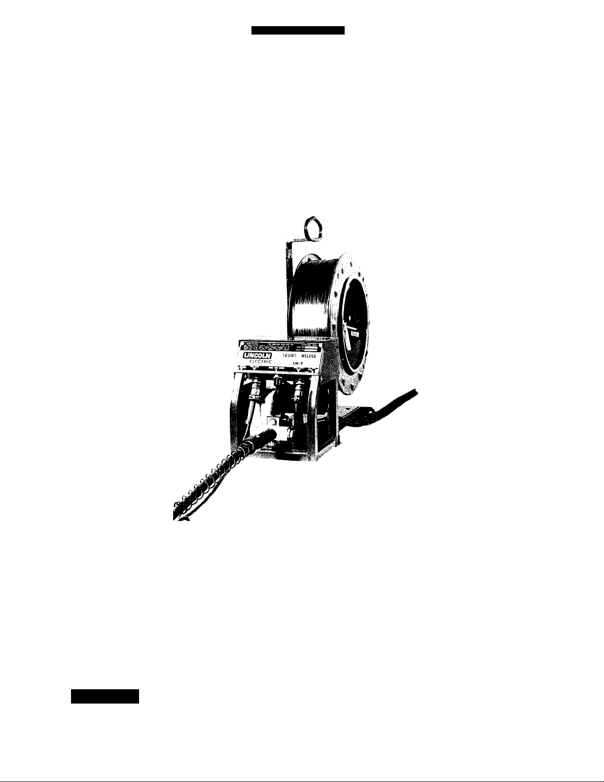
LN-7
SEMIAUTOMATIC WIRE FEEDER
IM-267
January, 1986
Shipping Damage Claims
When this equipment is shipped, title passes to the pur
chaser upon receipt by the carrier. Consequently, claims for
material damaged in shipment must be made by the pur
chaser against the transportation company at the time the
shipment is received.
............
LiWCOLiy
THE LINCOLN ELECTRIC COMPANY
World s Largest Manufacturer of Arc Welding Products • Manufacturer of industrial Motors
Sales and Service Worldwide
This manual covers
equipment which is
obsoiete and no ionger
in production by The
Lincoin Eiectric Co.
Specifications and
avaiiabiiity of optionai
features may have
changed.
Safety Depends On You
Lincoln arc welding equipment is designed and built with
safety in mind. However, your overall safety can be in
creased by proper installation .. . and thoughtful operation
on your part. DO NOT INSTALL, OPERATE OR REPAIR
THIS EQUIPMENT WITHOUT READING THIS OPERAT
ING MANUAL AND THE ARC WELDING SAFETY PRE
CAUTIONS ON THE INSIDE FRONT COVER. And, most
importantly, think before you act and be careful.
Cleveland, Ohio 44117-1199 U.S.A
Page 2

"7>
Arc Welding Safety Precautions
PROTECT YOURSELF AND OTHERS FROM POSSIBLE SERIOUS INJURY OR DEATH. READ
AND UNDERSTAND BOTH THE SPECIFIC INFORMATION GIVEN IN THE OPERATING
MANUAL FOR THE WELDER AND/OR OTHER EQUIPMENT TO BE USED AS WELL AS
THE FOLLOWING GENERAL INFORMATION.
1. HAVE ALL INSTALLATION, OPERATION,
MAINTENANCE AND REPAIR WORK performed
only by qualified people.
2. ELECTRIC SHOCK can kill.
Protect yourself from possible dangerous electrical
shock:
a. The electrode and work (or ground) circuits are elec
trically “hot” when the welder is on. Never permit
contact between “hot” parts of the circuits and bare
skin or wet clothing. Wear dry, hole-free gloves to
insulate hands.
b. Always insulate yourself from the work and ground
by using dry insulation. When welding in damp lo
cations, on metal floors, gratings or scaffolds, and
when in positions such as sitting or lying, make cer
tain the insulation is large enough to cover your full
area of physical contact with work and ground.
c. Always be sure the work cable makes a good electri
cal connection with the metal being welded. The
connection should be as close as possible to the area
being welded.
d. Ground the work or metal to he welded to a good
electrical ground.
e. Maintain the electrode holder, work clamp, welding
cable and welding machine in good, safe operating
condition.
f. Never dip the electrode in water for cooling.
g. Never simultaneously touch electrically “hot” parts
of electrode holders connected to two welders be
cause voltage between the two can be the total of
the open circuit voltage of both welders.
h. If using the welder as a power source for mechanized
welding, the above precautions also apply for the
automatic electrode, electrode reel, welding head,
nozzle or semiautomatic welding gun.
i. When working above floor level, protect yourself
from a fall should you get a shock.
Also see Items 6c and 8.
J-
3. FUMES AND GASES can be dangerous to your health.
a. Welding may produce fumes and gases hazardous
to health. Avoid breathing these fumes and gases.
When welding, keep your head out of the fume.
Use enough ventilation and/or exhaust at the arc to
keep fumes and gases away from the breathing zone.
When welding on galvanized, lead or cadmium
plated steel and other metals which produce toxic
fumes, even greater care must be taken.
b. Do not weld in locations near chlorinated hydrocar
bon vapors coming from degreasing, cleaning or
spraying operations. The heat and rays of the arc
can react with solvent vapors to form phosgene, a
highly toxic gas, and other irritating products.
c. Shielding gases used for arc welding can displace
air and cause injury or death. Always use enough
ventilation, especially in confined areas, to insure
breathing air is safe.
d. Read and understand the manufacturer’s instructions
for this equipment and the consumables to be used,
including the material safety data sheet (MSDS) and
follow your employer’s safety practices.
e. Also see item 9b.
4. ARC RAYS can injure eyes and bum skin.
a. Use a shield with the proper filter and cover plates
to protect your eyes from sparks and the rays of
the arc when welding or observing open arc welding.
Headshield and filter lens should conform to ANSI
Z87.1 standards.
b. Use suitable clothing made from durable, flame-
resistant material to protect your skin and that of
your helpers from the arc rays.
c. Protect other nearby personnel with suitable non
flammable screening and/or warn them not to watch
the arc nor expose themselves to the arc rays or
to hot spatter or metal.
5. FIRE OR EXPLOSION can cause death or property
damage.
a. Remove fire hazards well away from the area. If
this is not possible cover them to prevent the welding
sparks from starting a fire. Remember that welding
sparks and hot materials from welding can easily
go through small cracks and openings to adjacent
areas. Have a fire extinguisher readily available.
b. Where compressed gases are to be used at the job
site, special precautions should be used to prevent
hazardous situations. Refer to “Safety in Welding
and Cutting” (ANSI Standard Z49.1) and the operat
ing information for the equipment being used.
c. When not welding, make certain no part of the elec
trode circuit is touching the work or ground. Acci
dental contact can cause overheating and create a
fire hazard.
December 1985
-2-
Page 3

d. Do not heat, cut or weld tanks, drums or containers
until the proper steps have been taken to insure that
such procedures will not cause flammable or toxic
vapors from substances inside. They can cause an
explosion even though they have been “cleaned.”
For information purchase “Recommended Safe Prac
tices for the Preparation for Welding and Cutting
of Containers and Piping That Have Held Hazardous
Substances.”, AWS F4.1-80 from the American
Welding Society (see address below).
e. Vent hollow castings or containers before heating,
cutting or welding. They may explode.
f. Also see items 6c and 9c.
6. For Welding in General.
a. Droplets of molten slag and metal are thrown or
fall from the welding arc. Protect yourself with oil
free protective garments such as leather gloves,
heavy shirt, cuffless trousers, high shoes and a cap
over your hair. Wear ear plugs when welding out
of position or in confined places. Always wear safety
glasses when in a welding area. Use glasses with
side shields when near slag chipping operations.
b. Keep all equipment safety guards, covers and de
vices in position and in good repair. Keep hands,
hair, clothing and tools away from V-belts, gears,
fans and all other moving parts when starting,
operating or repairing equipment.
c. Be sure the work cable is connected to the work
as close to the welding area as practical. Work cables
connected to the building framework or other loca
tions some distance from the welding area increase
the possibility of the welding current passing through
lifting chains, crane cables or other alternate circuits.
This can create fire hazards or overheat lifting chains
or cables until they fail.
7. For Gas-Shielded Arc Welding.
a. Use only compressed gas cylinders containing the
correct shielding gas for the process used and prop
erly operating regulators designed for the gas and
pressure used. All hoses, fittings, etc. should be suit
able for the application and maintained in good con
dition.
b. Always keeps cylinders in an upright position sec
urely chained to an undercarriage or fixed support.
c. Cylinders should be located:
• Away from areas where they may be struck or
subjected to physical damage.
• A safe distance from arc welding or cutting oper
ations and any other source of heat, sparks, or flame.
d. Never allow the electrode, electrode holder, or any
other electrically “hot” parts to touch a cylinder.
e. Keep your head and face away from the cylinder
valve outlet when opening the cylinder valve.
f. Valve protection caps should always be in place and
handtight except when the cylinder is in use or con
nected for use.
g. Read and follow the instructions on compressed gas
cylinders, associated equipment, and CGA publica
tion P-1 “Precautions for Safe Handling of Compres
sed Gases in Cylinders” available from the Compres
sed Gas Association, 1235 Jefferson Davis High
way, Arlington, VA 22202.
8. For Electrically Powered Equipment.
a. Turn off input power using the disconnect switch
at the fuse box before working on the equipment.
b. Make the electrical installation in accordance with
the National Electrical Code, all local codes and the
manufacturer’s recommendations.
c. Properly ground the equipment in accordance with
the National Electrical Code and the manufacturer’s
recommendations.
9. For Engine Powered Equipment.
a. Turn the engine off before troubleshooting and
maintenance work unless the maintenance work re
quires it to be running.
b. Operate the internal combustion engines in open,
well-ventilated areas or vent the engine exhaust
fumes outdoors.
c. Do not add the fuel near an open flame, welding
arc or when the engine is running. Stop the engine
and, if possible, allow it to cool when refueling to
prevent spilled fuel from vaporizing on contact with
hot engine parts and igniting. Do not spill fuel when
filling tank. If fuel is spilled, wipe it up and do
not start engine until fumes have been eliminated.
d. In some cases it may be necessary to remove safety
guards to perform required maintenance. Remove
guards only when necessary and replace them when
the maintenance requiring their removal is complete.
Always use the greatest care when working near
moving parts.
e. Do not put your hands near the engine fan. Do not
attempt to override the governor or idler by pushing
on |he throttle control rods while the engine is run
ning.
f. To prevent accidentally starting gasoline engines
while turning the engine or welding generator during
maintenance work, disconnect the spark plug wires,
distributor cap or magneto wire as appropriate.
g. To avoid scalding, do not remove the radiator pres
sure cap when the engine is hot.
For more detailed information it is strongly recommended
that you purchase a copy of “Safety in Welding & Cutting
— ANSI Standard Z49.1” from the American Welding So
ciety, P.O. Box 351040 Miami, Rorida 33135.
December 1985
Page 4

Need Welding Training?
The Lincoln Electric Company operates the oldest and most respected Arc Welding
School in the United States at its corporate headquarters in Cleveland, Ohio. Over
60,000 students have graduated. Tuition is low and the training is “hands on”.
For details write: Lincoln Welding School
22801 St. Clair
Cleveland, Ohio 44117
and ask for bulletin ED-80 or call 216-481-8100 and ask for the Welding School
Registrar.
-4-
Page 5

The Lincoln Electric Company
Cleveland, Ohio 44117
SEC J1 INDEX
Sec. J2 INSTALLATION INSTRUCTIONS
Wire Feed Unit and Wire Reel....................................................................................................................................................... Sec. J2.2.1
Wire Feed Rolls and Guide Tubes..................................................................................................................................................Sec. J2.2.2
Gun & Gun Cable Assemblies . .....................................................................................................................................................Sec. J2.2.3
Input Cable: LN-7 to Power Source...............................................................................................................................................Sec. J2.3.1
Connection Diagrams; LN-7 to Lincoln Power Sources .............................................................................................................Sec. J2.3.2
Connection Diagrams: LN-7 to Other Power Sources.................................................................................................................Sec. J2.3.3
Optional Feature Installation
K-178 Mounting Platform ........................................................................................................................................................Sec. J2.5.3
Auxiliary Equipment Contacts .................................................................................................................................................Sec. J2.5.5
K-162 SpintUe for Mounting 10 thru 30 Pound Spools .........................................................................................................Sec. J2.5.7
K-163 Undercarriage ................................................................................................................................................................ Sec. J2.5.8
Sec. J3 OPERATING INSTRUCTIONS
I } Adjusting Current and Voltage.................................................................................................................................................................. Sec. J3.1.1
Arc Starting......................................................................................................................................................................................Sec. J3.1.2
Circuit Protection............................................................................................................................................................................Sec. J3.1.4
Wire Reel Loading - 50 and 60 Pound Coils ................................................................................................................................Sec. J3.1.5
Wire Reel Loading - 10 to 30 Pound Spools .................................................................................................................................Sec. J3.1.6
Sequence of Welding ...................................................................................................................................................................... Sec. J3.1.7
Wire Reel Changing........................................................................................................................................................................ Sec. J3.1.9
For Iimershield® operating techniques and procedures request
‘Timershield Production Welding Guide”, bulletin N675
Index
k
.
,„.y
Sec. J6 MAINTENANCE
Wire Drive Motor and Gear Box ..................................................................................................................................................Sec. J6.1.1
Drive Rolls and Guide Tubes .........................................................................................................................................................Sec. J6.1.2
Wire Reel Mounting........................................................................................................................................................................Sec. J6.1.3
Control Box..................................................................................................................................................................................... Sec. J6.1.5
Gun Cable ............................................................................................................... »..................................................................Sec. J6.2.1
Gun Disassembly — K-115 and K-126..........................................................................................................................................Sec. J6.2.2
Electrical Sequence of Operation...................................................................................................................................................Sec. J6.4
Troubleshooting ..............................................................................................................................................................................Sec. J6.6
Parts Lists.........................................................................................................................................................................................Sec. J7
Wiring Diagrams ....................................................................................................................................Filed at the back of this manual.
January 1976
-5-
Page 6

-6-
Page 7
f ^
The Lincoln Electric Company
Cleveland, Ohio 44117
SEC.J2.2 MECHANICAL INSTALLATION
Sec. J2.2.1
Wire Feed Unit and Wire Reel
The LN-7 is shipped ready to install in the work
location.
September 1971
Sec. J2.2.2
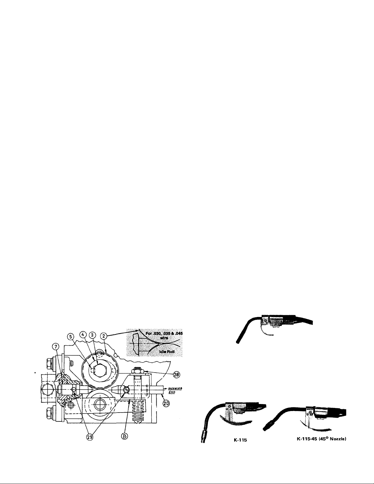
Wire Feed Rolls and Guide Tubes
NOTE: The maximum sizes the LN-7 will satisfactorily
feed are 7/64” Innershield® and 3/32” solid electrodes.
The drive roll, idle roll and guide tubes for the electrode
size specified on the order is shipped with the wire feed
unit. The electrode sizes that can be fed with each roll and
guide tube are stenciled on each part. Instructions to install
these parts on new machines or replace them on used
machines, are as follows;
A. Loosen the idle roll tension nut (item 28) approximately
3 full turns or use a screwdriver to pry the idle roll arm
down at point B .
B. Remove hex head screw (item 3) & the drive roll clamp
ing collar (item 4). (On new machines remove the tape &
drive roll key from the collar.) Insert the key (item 5)
into the keyway of the output shaft.
C. Wipe the drive roll & spacer surfaces clean. Install one
drive roll (item 2), then the spacer & the second drive
roll. (For .030, .035 & .045 electrode, the drive roll
is one piece. For '/i6 electrode there is no spacer).
D. Install drive roll clkmping collar & hex head screw pre
viously removed. Tighten hex head screw securely.
E. Back out the two guide tube clamping set screws (item
29).
F. Insert the outgoing guide (item 7) (the one with the plas
tic insert) into the front hole. The guide tube for .030",
.035" and .045" wire has a non-symetrical chisel end.
Be certain the contour with the larger radius and the
exposed oval opening for the wire faces the grooved
Assembly and Installation
drive roll. Push the guide tube back as far as it will
go and tighten the clamping set crew. Insert the incom
ing guide tube (item 20) into the rear hole as far as
it will go and tighten the clamping set screw. These
set screws are dog point. When the two tubes are instal
led properly these dog points will lock into the annular
groves that are in each of the guide tubes,
G. Tighten the idle roll tension nut (item 28) or remove the
screwdriver used as a wedge in step A. The tension nut
should normally be tightened until it bottoms for wire
sizes 1/16” and larger. For smaller wire sizes and alumi
num wire the tension nut should be loosened if the wire
tends to buckle in the guide tube, cable or between the
drive rolls and outgoing guide tube.
H. To change drive rolls and guide tubes for a different size,
reverse the above procedure.
September 1976
Sec. J2.2.3
Gun & Gun Cable Assemblies
General
The LN-7 is used with various guns. In all cases the gun
and cable are shipped assembled ready to weld. Use the gun
and cable assembly for the electrode type (solid or Innershield) and electrode size to be used.
Note; The guns described below were available at the
time this sheet was printed. They may not be today. See
Lincoln Specification literature for up-to-date information.
Innershield® Guns
Squirtgun K-126 is recommended for most welding with
.062 through 3/32" electrodes. Install the insulated nozzle
extension (or thread protector) and the nozzle contact tip
for the stickout and electrode size being used.
K-126
For heavy duty welding with 3/32” electrode use K-1153/32 or K-115-45-3/32. Install a 3/32” contact tip and the
insulated nozzle extension for the stickout being used.
For welding with 7/64” electrode, use K-115-3/32 with
a M-11474-.120 nozzle or a K-11545-3/32 with a
M-11510-.120 nozzle. Also install a 7/64” contact tip and
the insulated nozzle extension for the stickout being used.
-7-
Page 8
Assembly and Installation
Sec. J2.2.3 Continued
Gun Cable: LN-7 to Gun
Lay the cable out straight. Insert the connector on the
welding conductor cable into the brass block on the front
of the LN-7. Make sure it is all the way in and tighten the
locking screw with a 3/16” Allen Wrench. Keep this con
nection clean and bright. Insert the control cable polarized
plug into the receptacle below the nameplate.
Linconditioner'i’M Guns ^
For locations where smoke accumulation is a problem
and conventional exhaust systems are ineffective, the
available smoke removal type Innershield guns and vacuum
units can be used. Instructions are shipped with the
equipment.
April 1974
The Lincoln Electric Company
Cleveland, Ohio 44117
-8-
Page 9
The Lincoln Electric Company
Cleveland, Ohio 44117
SEC. J2.3 ELEaRICAL INSTALLATION
Sec. J2.3.1
Input Cable: LN-7 to Power Source
The input cable between the wire feeder and the power
source consists of a four-conductor control cable and an
electrode cable. The control cable has lugged leads on the
power source end and a polarized plug on the wire feeder
end. With the power source turned off, install the input
cable per the following instructions: i
I. Connect the end of the control cable with the lugged
‘.-leads to a constant voltage type power source. For
Lincoln power sources follow exactly thé instructions
(including all jumpers on the power source terminai
strips) for the specific power source per the wiring
diagrams in Sec. J2.3.2.
Assembly and Installation
lead length should not exceed 400’. When using the
longer lengths of extension cables, it may be necessary
to add parallel electrode cables to limit the voltage drop
in the cable.
4. Loosen the screws holding the clamp to the rear vertical
support of the wire feeder frame. Put only the electrode
cable under the clamp.
5. Coimect the end of the electrode cable to the end of the
brass block on the wire feeder using the bolt provided.
Be sure the cable is placed to allow easy access to the
drive roll and guide tube screws. (See photo below.)
Tighten the screws on the electrode cable clamp.
6. Run the control cable under the wire feed motor and
insert the plug into the mating receptacle below the
LN-7 nameplate.
2. For constant voltage power sources not included in Sec.
J2.3.2, request a copy of Sec. J2.3.3 for connection
instructions.
7. Connect a ground lead of sufficient size and length (per
the following table) between the To Work’ stud on the
power source and the work. Be sure the connection to
the work makes tight metal-to-metal contact.
Current
Amps
60% Duty Cycle
300 0
400 00
500 00 000
600 000 0000
Copper Ground Cable Length
Up to 50' 50' - 100'
00
000
3. If input cables longer than the standard length (available
as 7, 25, 50, 75 and 100’ lengths) must be used, 50’
K-177 extension cables can be installed. These have
polarized plugs on each end of the control cable and a
4/0 electrode cable. Install the extensions between the
standard input cable and the wire feeder. Total input
September 1976
-9-
Page 10

Sec. J2.3.2
Connection Diagrams:
LN-7 to Lincoln Power Sources
The Lincoln Electric Company
Cleveland, Ohio 44117
To an Idealarc R3S-250
pow£g 5oue.ce
SHQSA/S ¿LtC,TfZQoe C0NN£CT€0 PoS/r/^e.TO
v^o^jc. ce/ias at thc Pov^ee. so</€ce.
POLAA/ry^ /e£'^€jese 7HC e.C€CT&00€ ^NO
To a SAN Welder
FW£R SOURCL 5- 14176
5- 14671
6- 25-71
6- 25-71
To an Idealarc R3S-400, 600 or 800 Welder
ABOV£ ^OWS £LECTffQD£ CXitJNECrLD P05l7li^£.
TO (M/9NGC fitPLAmry, R€V£»S£ TN£ £UCr/fOP£ AND WORJ< l£ADS
/ir ^SOaffC£.
To a SAM Motor-Generator or Engine Welder
5- 14179
6- 27-75
S-14177
9-24-76B
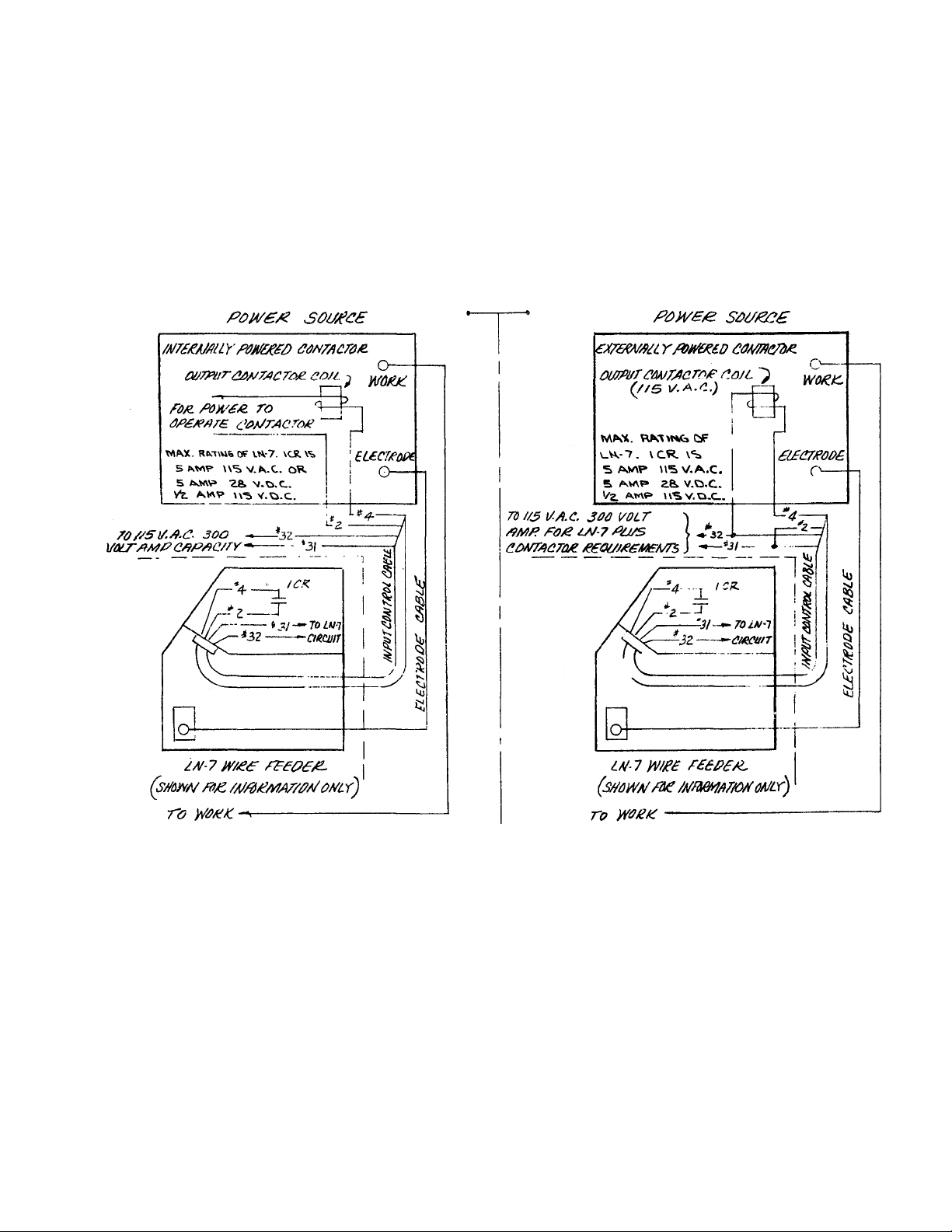
To Power Sources Without Output Contactor
Requiring A K-240 Contactor Kit
» i€ttOS mio. rnm OA‘S€A*^'r«4. r
Msv. MMi. fOAn^mccr
Aoe ste AA/ar<. Mr
/AfMAr <WE?
(MOK ■
NA. n» V.AC. wax l|
oi~AUTBWATiC*
R.R. CtAOS »2L*75.*T(*.*‘>7. i OWD. OONOTAPPeAH LM-7 COMTROU CA&Lt
N.C. WttMWe CARLC^ MOST sc Of PKOFIA 4*mCITt fftH THC CUKtW A»B BdTV CVCU Of 1W>M>M>KTt AW PUTUW
APPUCATHWR
¡J R6. TUKMtO OFF WHCM PQWH »OUKC« ta TUfcitCO OFF. COMtACTftg Kff AHOt«*\-WTOWATIC
BlPTMEMT WHX9Tn.L AAVC W3 V. CaWTIOL rftWKE SUmiEP UHTH. POWtl TO TetwiUAL^
<•& 1\m>€0 OFF.
To a SAF-600, SA-800 or SAF-600-B ("-OA") Welder
5- 15416
6- 18-76
cAeie
'•JO seMf-AuroMMue
Se<WBM4J/C SMUAfl
10-
Page 11
The Lincoln Electric Company
Cleveland, Ohio 44117
ELECTRICAL INSTALLATION - CONT’D
Sec. J2.3.3
Connection of LISI-7 to Other (Not included in Sec. J2.3.2) Power Sources
POW£RSO(/£C£S
TO yT/je/^/'G of POJVFF SOUFCe to
BE useo TO m/o t/te tyae of coArrooroF. o/foo/T
Assembly and Installation
-11
January 1976
Page 12

Assembly and Installation
SEC. J2.5 OPTIONAL FEATURES INSTALLATION
Sec. J2.5.3
K-178 Mounting Platform — LN-7 on Idealarc R3S
This is a turntable type platform for mounting the LN-7
on the top of Idealarc R3S power sources. Bolt the plat
form to the lift bail per instructions supplied with the
platform.
The Lincoln Electric Company
Cleveland, Ohio 44117
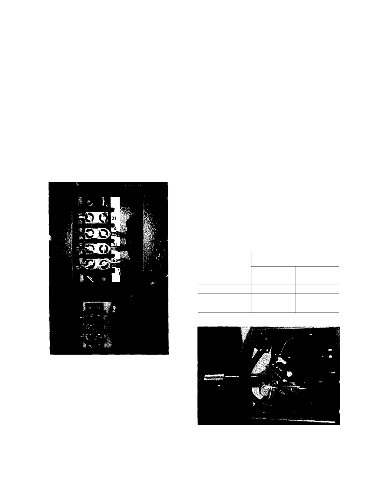
Route the leads thru the hole in the bottom of the con
trol box to the terminal strip. Spare quick connect ter
minals are provided on the terminal strip. Remove these
terminals and crimp them to the lead wires. Connect the
leads to numbers 32A and 7 on the terminal strip. Install a
suitable cable clamp on the leads to prevent excess tension
on the terminals and protect the lead insulation at the edge
of the hole.
March 1973
Sec. J2.5.7
K-162 Spindle For Mounting 10 thru 30 Pound
Spools
To mount the spindle kit for 10 thru 30 pound spools,
remove the shaft for the standard 50-60 pound wire coils
from the mounting framework. Install the spindle per the
instructions shipped with the kit.
Adjust the brake tension screw (see Sec. J3.1.6) on the
spindle as needed.
September 1971
September 1971
Sec. J2.5.5
Auxiliary Equipment Contacts
The Power for 115 volt AC auxiliary equipment can be
obtained from the terminal strip inside the control box.
The contacts are “hot” only when the gun trigger is oper
ated. The current draw of this circuit must not exceed 1/4
ampere.
Sec. J2.5.8
K-163 Undercarriage
The undercarriage includes the wheels, handle and hard
ware. Mount the casters at the front and the wheels to the
rear of the platform. Be sure the round, rear axle is to the
rear of the mounting bolts that hold the U-shaped axle
member to the frame. Bolt the handle to the front of the
platform so the LN-7 can be tilted back and wheeled like a
two-wheel truck. Holes for installing the wire reel support
are provided in the platform.
September 1971
12-
Page 13

The Lincoln Electric Company
Cleveland, Ohio 44117
Operating Instructions
SEC J3 OPERATING INSTRUCTIONS
Sec. J3.1.1
Adjusting Current and the Voltage
Use only constant voltage type power sources. If using a
multiple process power source, be sure it is set for constant
voltage output per instructions in the manual for the power
source.
Set the voltage using the controls on the power source.
For the most accurate arc volt^e readings, connect the
meter leads between the work and the brass gun cable con
nection block of the LN-7 and read the voltmeter while
welding. Approximate welding voltages can be obtained by
reading the power source voltmeter while welding.
On constant wire feed speed type wire feeders like the
LN-7, welding current is controlled by the wire feed speed.
With the ‘Wire Feed Speed’ control set on Min. the wire
feeds at a little under 50” per minute and the welding
current is low. When set on Max., the electrode feeds at
more than 500” per minute and the welding current is high.
If the power source is equipped with meters, the welding
current can be read directly on the anuneter while welding.
If the power source has no meters and the relationship
between current and wire feed speed is known, current can
be accurately set by measuring the wire feed speed. To
measure wire feed speed disconnect the electrode cable at
the power source:
1. Press the gun trigger and feed electrode for 15 seconds.
2. Measure the wire feed in inches and multiply by 4. This
gives the wire feed speed in inches/minute.
3. Adjust the ‘Wire Feed Speed’ control until the desired
speed is obtained.
January 1976
Sec. J3.1.3
Circuit Protection
The AC input line is protected by both a circuit breaker
and a fuse.
The circuit breaker protects the LN-7 from moderate
overloads, usually caused by excessive wire drag or other
wire feeding problems. To reset the circuit breaker, push
the red button on the underside of the control box. If it
opens again, determine the cause of the overload.
The fuse protects the LN-7 from sudden high current
overloads such as a shorted motor or other short circuit
conditions. Determine and correct the cause of overloading.
Replace the fuse with one of the same size and type.
November 1972
Sec. J3.1.4
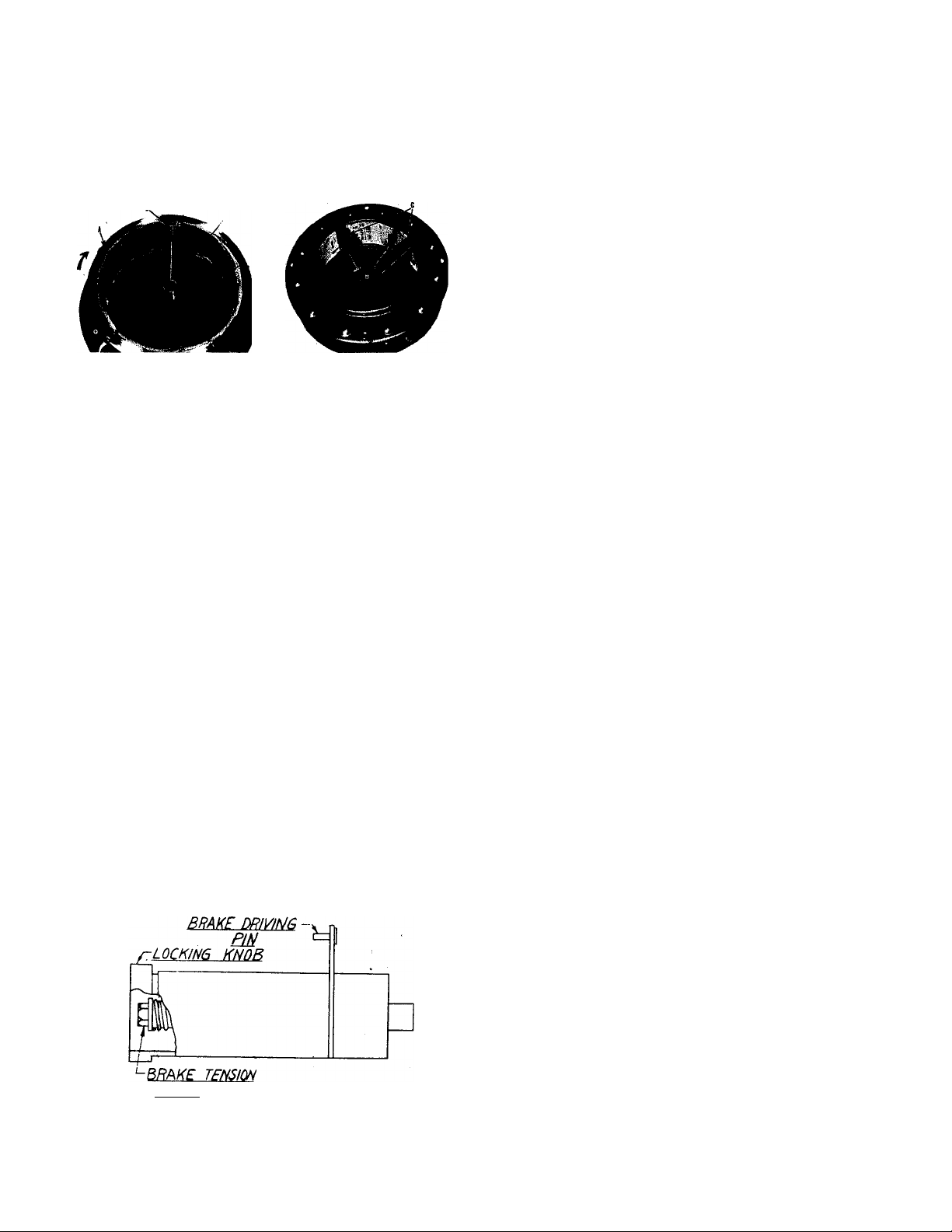
Adjustable Wire Reel Brake
The mount for standard 50 and 60 pound electrode coils
includes a two position brake assembly. Generally the
brake should be at the inner position (nearest to the wire
reel shaft) for wire feed speeds below 400”/min. It should
be at the outer position for the faster wire speeds often
used when feeding small diameter electrode.
To adjust the brake position, remove the wire reel. Pull
the cotter pin that holds the brake shoe to the arm, move
the shoe and replace the cotter pin. Do not bend the cotter
pin — it is held in place by a friction fit.
Machines built before November 1972 do not have an
adjustable brake.
See Sec. J3.1.6 for adjustment instmetions for the brake
on the spindle for 10-25 pound spools.
November 1972
Sec. J3.1.2
Arc Starting
The LN-7 starts at a slow wire feed speed and low cur
rent and automatically accelerates quickly to the welding
speed set by the ‘Wire Feed Speed’ control. The electrode
should be lightly touching the work when the gun trigger is
pressed. This low starting current improves the starting
characteristics and minimizes skipping, stubbing, and spat
ter when striking the arc with both normal and Line-Fill
long stickout welding procedures. This standard feature
requires no adjustment.
September 1976
Sec. J3.1.5
Wire Reel Loading — 50 and 60 Pound Coils
1. To remove the wire reel from its shaft, grasp the spring
loaded knob and pull it out. This straightens the knob so
it seats into the shaft when released. Remove the reel.
2. Lay the reel flat on the floor, loosen the spinner nut and
remove the cover plate.
3. Before cutting the tie wires place the coil of electrode on
the reel so it unwinds as the reel rotates clockwise.
A. Be sure the coil is placed so the spring loaded arms
will not interfere with the later removal of the coil tie
wires. (See photo.)
B. When loading .035 and .045” electrode, be certain
the coil is placed on the reel so the spring loaded arms
-13-
Page 14
Operating Instructions
The Lincoln Electric Company
Cleveland, Ohio 44117
are at the center of the slots in the carboard coil liner.
This provides the positive compression of the coil
needed for trouble free wire feeding. (See photo).
C. Put the cover plate on the reel so the four arms of the
cover straddle and are in line with the spring loaded
arm of the reel proper.
4. Tighten the cover as much as possible by hand. DO NOT
hammer on the spinner nut arms.
5. Cut and remove only the tie wire holding the free end of
the coil. Insert the free end into one of the holes in the
cover and secure it by bending it back. Cut and remove
the remaining tie wires.
NOTE; Always be sure the free end of the coil is
securely held while the tie wires are being cut and until
the wire is feeding through the drive rolls. Failure to do
this will result in “back lashing” of the coil, which may
tangle the wire. A tangled coil will not feed so it must
either be untangled or discarded.
6. Replace the reel on the wire feeder. Grasp the shaft
knob, pull it out and swing it across the reel hub.
7. Turn the reel until the free end of the electrode is acces
sible. While tightly holding the electrode, cut off the
bent end. Straighten the first six inches and insert it
through the wire guide to the drive roEs. Press the gun
trigger untE the rolls pick up the wire and feed it
through the gun cable.
WARNING: When inching, the electrode is always “hot” to
ground.
September 1971
Sec. J3.1.6
Wire Reel Loading — 10 to 30 Pound Spools
Remove the locking knob from the shaft. Place the 25
lb. spool on the shaft making certain the brake driving
pin enters one of the holes in the back side of the spool.
Replace and tighten the locking knob. Be certain the wire
comes off the reel in a clockwise direction. The spool
should turn freely without any overrun. Adjust the brake
tension with the hex head screw on the shaft hub, until
the reel turns freely but with little or no overrun.
Sec. J3.1.7
Sequence of Welding
See page 2 for general arc welding safety precautions.
1. Install the LN-7 per Sec. J2.
2. Load the wire reel per Sec. J3.1.5 or J3.1.6.
3. Ground the work.
4. Set the power source polarity switch or properly con
nect the electrode and ground lead for the correct elec
trode polarity.
5. Set the voltage using the power source controls per Sec.
J3.1.1.
6. Set the current per Sec. J3.1.1.
7. Press the gun trigger to inch the wire untE it sticks about
3/4” beyond the end of the gun. Position the gun so the
electrode is l^tly touching the work. Avoid pushing the
electrode against the work before starting to weld. Press
the gun trigger to start welding. Current can be adjusted
whEe welding using the ‘Wire Feed Speed’ control on the
LN-7.
8. To stop welding, release the gun trigger and lift the gun
from the work. The wire feed motor stops and the weld
ing circuit is de-energized the moment the trigger is
released. If an auxEiary device is connected to #7 and
#32 in the LN-7 control box, (See Sec. J2.5.5), this
device is de-energized when the trigger is released.
Sec. J3.1.9
May 1975
Wire Reel Changing
At the end of a coE remove the last of the old electrode
coil from the conductor cable with the foUowing
procedures:
1. Cut the end of the electrode off at the gun end. Do not
break it off by hand because this puts a slight bend in
the wire making it difficult to pull it back through the
nozzle.
2. Uncouple the gun conductor cable from the connection
block on the LN-7 drive unit.
3. Lay the gun and cable out straight.
4. Using pliers to grip the wire, puU it out of the cable from
the connector end. Do not puU it from the gun end.
5. After the electrode has been removed, connect the gun
conductor cable back to the LN-7.
SCRPW
Load a new reel of electrode per the instructions in Sec.
J3.1.5 or J3.1.6.
September 1971
-14-
Page 15

The Lincoln Electric Company
Cleveland, Ohio 44117
WARNING: Have a qualified electrician do the maintenance and trouble shooting work.
Turn the input power off at the power source before working inside the wire feeder.
Maintenance Instructions
SEC. J6.1 WIRE FEEDER MAINTENANCE
Sec. J6.1.1
Wire Drive Motor and Gear Box
Every year inspect the gear box and paint the gear teeth
with graphite grease.
Every six months check the motor bmshes. Replace
them if they are less than 1 /4” long.
September 1971
Sec. J6.I.2
Drive Rolls and Guide Tubes
Periodically inspect the drive roll section. Clean it as
necessary. Do not use solvents for cleaning the idle roll
because it may wash the lubricant out of the bearing. The
drive roll, idle roll and guide tubes are stamped with the
wire sizes they will feed. If a wire size other than that
stamped on the rolls is to be used, the rolls and guide tubes
should be changed.
The drive roll for 1/16, .068, 5/64, 3/32 and 7/64” elec
trode have a double set of teeth so they can be reversed for
additional life. Between the two knurled rolls (except
1/16” rolls) is a shim washer which limits the damage to the
electrode if wire feeding problems occur. See Sec. J2.2.2
for roll changing instructions.
Drive rolls for .045 and .035 electrodes have no teeth.
They are not reversible.
September 1971
Sec. J6.1.3
Wire Reel Mounting — 50 and 60 Pound Coils
To prolong the life of the reel shaft, periodically coat it
with a thin layer of grease.
No maintenance of the two position adjustable brake
installed on machines built after November 1972 is needed
except to replace the shoe assembly if it wears through.
November 1972
Sec. J6.1.5
Control Box
The control box requires no routine maintenance.
September 1971
SEC J6.2 GUN AND CABLE MAINTENANCE
Sec. J6.2.1
Gun Cable
A dirty gun cable can cause rough and erratic wire feed
ing. Therefore, the cable liner must be cleaned periodically.
Remove the cable from the wire feeder. Lay it out
straight on the floor. Remove the contact nozzle tip from
the gun. Using an air hose and only partial pressure, gently
blow out the cable. Work the full length of the cable by
bending it back and forth then blow it out again. Continue
this procedure until cable is clean.
October 1981
Sec. J6.2.2
Gun Disassembly: K-115 and K-126 Innershield
Squirtguns
To remove the nozzle from the gun, loosen the 3/16”
Allen head screw in the gun handle and pull the nozzle
straight out. To reinstall, insert the nozzle into the gun
handle. Push it in as far as possible and tighten the Allen
head screw.
To disassemble Innershield Squirtguns K-115 and K-126,
first loosen the screws which hold the heat shield in place.
Remove the heat shield.
To disassemble the switch housing from all these guns,
remove the four screws holding the saddle around the gun
handle. Then hold the housing with the cable toward the
floor and look into the switch cavity. The tight side of the
larger roll pins is to the right. Drive these pins to the left.
They can be easily removed when they clear the right side
of the casting. Do not remove the smaller roll pins unless
the trigger is being replaced. The height of the Z spring
controls the operating point of the switch with respect to
the trigger movement. Set the spring so the switch operates
at about the mid-point of the trigger travel.
To remove the handle from the cable, slip the spatter
shield out of the front of the handle. Remove the 1/4-20
socket head screw through the hole in the side of the
handle. Then pull the handle back on the cable. Remove
the snap ring and connector clamp and the handle can then
be shpped off the cable.
September 1971
-15-
Page 16

Operation
The Lincoln Electric Company
Cleveland, Ohio 44117
SEC J6.4 LN-7 SEQUENCE OF OPERATION
Start Generator
I
Press Gun Trigger
Closes 524-525
I
Energizes 1 CR
Closes 2-4
pilot relay
and/or I
Energizes welder
Contactor
Electrode now
“hot” to ground
Closes 627-539
I ^
Connects wire feed
motor to
power board
1
Energizes
control board
at low speed and increases
Opens 539-514
2CR and dynamic
brake resistor
Wire feed motor starts
speed to welding speed
I
Arc starts
i
Welding
Release Gun Trigger
I
Opens 524-525
De-energizes 1 CR
I
Disconnects
motor from
Closes 7-31A
Energizes 7-3 2A
auxiliary equipment
I
(for optional
user supplied)
Opens 2-4
De-energizes
welder pilot
relay
and/or I
De-energizes
welder
contactor
Electrode is
cold to work
Closes 539-514
Opens 539-627
... I
Disconnects wire
feed motor from
power board
De-energizes
control board
I
----------------1--------------Wire feed motor stops
^ •
Connects wire
feed motor to
2CR and dynamic
brake resistor
Motor braking current
__________
I
pulls in 2CR
Shorts out relay
1 CR to prevent
it pulling in
while motor
brake current is
flowing
I
Opens 7-31A
De-energizes
auxiliary equipment
I
2 CR drops out
Unit ready for next weld
I
-16-
January 1972
Page 17

The Lincoln Electric Company
Cleveland, Ohio 44117
WARNING: Have a qualified electrician do the maintenance and trouble shooting work.
Turn the input power off using the disconnect switch at the fuse box before woricing
inside the machine.
Maintenance Instructions
SEC J6.6 TROUBLESHOOTING
Trouble Cause
1. Rough wire feeding or wire not
feeding but drive rolls turning.
2. Variable or “hunting” arc. a. Worn and/or melted contact tip.
3. Weld Porosity, narrow and ropey
bead, or electrode stubbing into
plate when welding.
4. LN-7 circuit breaker trips while
welding.
LN-7 or power source electrical
problems such as:
LN-7 fuse blows.
Power Source Fuse blows.
LN-7 circuit breaker trips.
No control of wire feed motor.
Wire feed motor won’t run.
Auxilliary equipment connected
to 32A and 7 won’t work.
Power source contactor won’t
work, but LN-7 feeds wire.
a. Gun cable kinked and/or twisted.
b. Wire jammed in gun and cable.
c. Incorrect drive rolls and guide
tubes.
d. Drive rolls loose.
e. Gun cable dirty.
f. Worn drive rolls.
g. Electrode rusty and/or dirty.
h. Worn nozzle liner,
j. Partially flashed or melted
contact tip.
b. Worn or undersize work cable
or poor work connection.
c. Loose electrode connections.
a. Dirty plate or improper
procedures.
a. See Trouble 1 above.
b. High ambient temperature
(causing circuit breaker to trip.)
c. Electrical problems in power
source or LN-7.
a. Loose connection or broken lead.
b. Electrical component has failed.
What to Do
a. Inspect gun cable and replace if necessary.
b. Remove wire from gun and cable — feed in new
wire. Note any obstructions in gun and cable.
Replace gun and cable if necessary.
c. Check wire diameters stamped on drive rolls,
wire guides, and drive roll spacers for correct
combination for wire being used.
d. Remove, clean, install and tighten.
e. Clean per Sec. J6.2.1.
f. Replace and/or reverse split drive roll type.
g. Replace.
h. Replace.
j. Replace contact tip.
a. Replace tip - remove any spatter on end of tip.
b. Inspect - repair or replace as necessary.
c. Be sure electrode lead is tight. Gun cable tight
in wire feeder contact block. Gun nozzle and
gun tip tight.
See trouble shooting information in Bulletin
N676, “Innershield Semiautomatic Welding
Guide.”
a. Correct problems.
b. Provide better ventilation for LN-7.
c. See Trouble 5.
a. Turn power source and LN-7 off and check
leads and connections.
b. Replace blown fuses or reset circuit breaker
and try to weld. If trouble recurs, call Lincoln
semiautomatic distributor, local representa
tive or authorized Field Service Shop.
-17-
October 1971
Page 18

Sec. J7.2
Page 109-C
The Lincoln Electric Company
Cleveland, Ohio 44117
LN-7 WIRE FEEDER
ITEM
1
<5
12
Parts List P-109-C
PART NAME AND DESCRIPTION
Gun a nd Ca bl e As se m bl y Se e Se c .
2
Con tr ol Bo x Se e
Sel f Ta p pi ng S cr ew (C on tr ol B o x 6 Co ve r to F r am
4
Wir e Dr i ve M ec ha ni s m Se e
inp ut C a bl e an d Ex t en si on C ab l e As se mb ly See
6
Wir e Ree l Sup po rt (50# and 60# ) See
Wir e Ree l Sha ft See
7
Dri ve U n it F ra me A s se mb ly
3
Nam ep la t e
Sel f Ta p pi ng S cr ew to M ou nt N a me pl at e
18-
NO.
REQ’D.
J7. 3
109 -D
0 6
109 -F
loq -H
107 -0
107 -P
1
1
4
Page 19

The Lincoln Electric Company
Cleveland, Ohio 44117
Sec. J7.2
Page 109-D
CONTROL BOX
ITEM
Complete Control Box, Includes:
I
Case
2
P.C. Board Insulation
Control Circuit P.C. Board 1
3
Plastic Expansion Nut 2
4
Round Head Screw 2
Lockwasher 2
Grommet 1V,
5
6
Fuse Holder 1
Lead Clamp 1
7
Sems Screw 1
Hex Nut
8
Potentiometer 1
Relay Socket 1
9
C p I n Q
Round Head Screw 2
Lockwasher 2
II
12
Hex Nut
Circuit Breaker
T ransformer
Round Head Sr.rew
10 А.Г.. Relfly
PART NAME AND DESCRIPTION
___________________________________________________
Parts List P-109-D
NO.
REQ'D.
I
1
7
1
1
2
1
1
1
1
1
2
2 27
1
1
_____
2—
Item
l3
15
16
17
18 P.C. Board Receptacle
20 Round Head Screw
21 Insulating Washer 3
22 Resistor
23 Flat Washer
2k Lockwasher
25
26 Terminal Strip
Parts Not Illustrated
PART NAME AND DESCRIPTION
Lockwasher
Hex Nut
Reed Switch Assembly
Terminal Strip (Small)
Resistor (1/2 Watt)
Resistor (2 Watts)
Reed Switch Coil
Reed Switch
Route Head Screw
Lockwasher
Hex Nut
Power Circuit P.C. Board
Seif Tapping Screw
Plastic Expansion Nut
Input Polarized Plug
Self Tapping Screw
OutDUt Polarized Plua
Self Tapping Screw
P.C. Board Receptacle
Hex Nut
Res istor
Control Box Cover
Mftnnt-ari ta TriWAr
-------------------------------------------------------------------------
-
May 1972
NO.
REQ’D.
2
2
1
1
1
Ì
1
1
2
2
2
I
2
2
1
A
1
4
1
1
1
1
1
1
1
1
1
1
19-
Page 20

Sec. J7.2
Page 109-F
WIRE DRIVE MECHANISM
NOTE A; When ordering these parts, always specify wire size.
Some of these parts can be used for more than one wire size. All
suitable sizes are stenciled on each part.
Complete kits containing items 2, 7, 20, 22 and €5 are available
for wire sizes .035, .045, .052,1/16, .068, 5/64,3/32 and 7/64"
wire diameters. Order "LN-7 Wire Size Conversion Kit For
(specify wire size) Wire."
The Lincoln Electric Company
Cleveland, Ohio 44117
Parts List P-109-F
ITEM
1 Drive Motor and Gear Box, includes:
Drive Motor 1
Drive Motor, Includes
Gear Box
2* Drive Roll - Specify Wire Size 19
------
Ordli 2 foils for 1/16 -y/siy------------------------------------------
Hex Head Screw
3
Collar AssemblV
4
Key 1
5
6 Socket Set Screw 1
7*
Outqolnq Guide Tube - Specify Wire Size 1
Conductor Block Assembly 1
Insulating Bushing
9
10 2
11
Slotted Headless Set Screw 2
Hex Head Screw
l.Qckwashe.r-------------------------------------------------------------
_L2_
PART NAME AND DESCRIPTION
Pinion Gear 1
Rol1 Pin 1
NO.
REQ’D.
1
1
1
1
1
2
2
__2
______
-20-
ITEM
Conductor Block Insulation
13
11)
Socket Set Screw
Pivot pin
15
16 Idle Roll Assembly
Round Head Screw
17
Spring
18
Retaining Ring
20*
Incoming Guide Tube - Soecifv Wire Sire
21
Idle Roli Pull Arm
22*
Spacer - Specify Wire Size - For .068 - 7/6V'
Wi re
Locator Bushing
23
2l|
Hex Head Screw
25 *
Outgoing Guide Tube Insert - Soecifv Wire Size I
26
Flatwasher
Flatwasher 1
27
78
*
See MOTE A Above
PART NAME AND DESCRIPTION
NO.
REQ'D.
1
1
1
1
_J
_______
1
1
1
1
1
-1
November 1972
Page 21

The Lincoln Electric Company
Cleveland, Ohio 44117
U
Sec. J7.3
Page 103-F
K-115 SQUIRTGUN AND CABLE
WHEN ORDERING GIVE: Item No.,
Part Name, Parts List No., and Gun
*Specify wire size.
tSpecify 15’ or 10’ cable as appropriate.
Nozzle
Nozzle ^
linner ^
Nozzle ^
insert
Insert
retainer
Locking
screw ^
! I' I L*_ contact
Li-Li tip
ITEM
t *
1 +
1 r
2
3
Gun and Cable Assembly
Conductor Cable. Includes:
lA
IB
Snap Ring 1
Seat*^Shield Assembly
PART NAME AND DESCRIPTION
Handle and Stiffener, Wire Feeder End
Connector, Wire Feeder End 1
rnnnArtnr Run FnH
Pan Head Screw
6
Spatter Shield
7 Socket Head Screw
“8“
9*
q ^
Handle
Nozzle (82°) Includes:
Nozzle (4So) Includes:
Nozzle Liner, Tight Wound Steel Spring
9BV
9C
9D
lot
Nozzle Insert
NoZ2:le Insert Retainer
Liner Locking Screw
Trigger and Control Cable Assembly
Assembly Parts
11
11
11
12*
12*
17*
15
17
Insulated Guide, 2-3/4" Electrical
Insulated Guide, 3"3/4" Electrical
Insulated Guide, 1-1/4" Flertriral
Contact Tip, .120 Electrode
Contact Tip, 7/64 Electrode
r<-.r,<-=<-t Tin ■J/PO FlertrrwHe
5WItcfi Houirng^CTamp
Shield Mounting Block
Round Head Screw
Parts List P-103-F
NO.
REQ’D.
_J
_L
_]
_J
Ins-K
See P-
St 1ckout 1
St i ckout 1
St i rl/nnt
__________As
As
As
_1
Req' d.
Req' d.
}<an ' rl
_4
August 1974
1
______
1
1
4
1
______
1
1
____
1
1
1
1
1
_____
1
_______
-21-
Page 22

Sec. J7.3
Page 103-J&K
The Lincoln Electric Company
Cleveland, Ohio 44117
K-126 SQUIRTGUN AND CABLE
K-126 - Parts List P-103-J
ITEM
Gun and Cable Assembly
t
1 Handle
2 t
2A
2B
2C
2D
•i
A
5
6
1
8 Contact Tip, 5/6^“ Electrode As Req' d
8
“8
10
lOA Nozzle Liner, Tight Wound Steel Spring 1
IOS
IOC
10D Liner Locking Screw
11 t
12 Clamp
rr~
13
1Í*
18
PART NAME AND DESCRIPTION
Conductor Cable, Includes: 1
Handle and Stiffener, Wire Feeder End 1
Connector, Wire Feeder End
Connector, Gun End
Clamping Tube, Both Ends 2
Snao Rina
Clamp
Spatter Shield
Pan Head Screw A
Socket Head Cap Screw 1
Contact Tip, 3/3 2 “ Electrode Ai Reg' d
Contact Tip, .06 8 “ Electrode As Req' d
Nozzle Assembly, Includes 1
Nozzle Insert 1
Nozzle Insert Retainer 1
Trigger and Control Cable Assembly
Assembly Parts See -103-K
Insulated Guide, 2-3/^" Electrical Stlckout 1
Thread Protector, 3/1* to 1-1/2" Stlckout 1
Round Head Screw
August 1974
NO.
REQ'D.
1
1
I
1
1
I
1
1
1
...-4
TRIGGER AND
1
CONTROL CABLE ASSEMBLY
Cable Assembly - Parts List P-103-K
ITEM
t Trigger and Control Cable Assembly, Includes:
1 Micro-Switch
2
3
A
5
6 Roll Pin
7
8 Insulating Sleeving
9
10
12
12A
PART NAME AND DESCRIPTION
Switch Pad
Trigger Assembly
Cord Clamo
Coil Spring
Roll Pin
Set Screw
Cord Clamp
Polarized Plug, Wire Feeder End, Not lllus.
Clamp at Polarized Plug
August 1974
_
NO.
REQ'D.
1
1
1
1
1
2
2
2
1
1
1
1
1
Page 23

The Lincoln Electric Company
Qeveland, Ohio 44117
Sec. J7.3
Page 107-0
50 AND 60 # WIRE REEL SUPPORT
/
ITEM
Wire Reel Support Assembly, includes; 1
1 W i re Ree1
3
10
2
if
5
6
7
8
9
13
Reel Support
Reel Mounting Shaft Assembly 1
Optional Wire Reel Cover Parts Kit, includes;
\iire Reel Housing
Flatwasher
Lockwasher
Hex Nut
Hex Head Screw
Insulating Washer 12
Insulating Tube
Insulatina Tube
Optional Door Parts Kit, includes;
(Wire Reel Cover Must Be Installed.)
Door and Hinge Welded Assembly 1
Catch 1
Sems Screw (Catch Mounting)
Sealing Panel
\
Parts List P-107-0
PART NAME AND DESCRIPTION
NO.
REQ’D.
1
1
'-107-F
1
1
6
3
3
3
1
2
1
2
1
■23-
January 1973
Page 24

Sec. J7.3
Page 107-P
WIRE REEL SHAFT
APf>ty LINCOLN BEARING <M£ASt PER £-IU7 TO ALL MAT/N6
SURPACE.S AND TO tdt Q.Q. Of THE SPPIN^ AtPOPS.
A^sd^QCY WTO Tuj SUAPT ihiJL.
The Lincoln Electric Company
Cleveland, Ohio 44117
SOPPOfeT
PPPME -
Parts List P-107-P
ITEM
Reel Mounting Shaft Assembly, Includes: 1
2
Flat Spring Steel Washer 2
Reel Mounting Shaft
3*
ii
Sprl ng
Flat Sorinq Steel Washer
5
6 Rivet
Rol1 Pin
7
8 Pu11 Knob
Snap Ring
9
10
12
13
lit Insulating Vilasber
15
16
18 Brake Assembly
*
Bronze Washer
Flatwasher
Hex Head Screw
17
LN"7 welders built before November 1972 did not
have the adjustable brake (Item 18). If a shaft
or fixed brake assembly is needed, order the
complete shaft assembly.
PART NAME AND DESCRIPTION
Insulatina Washer
insulating Tube
Lockwasher
INPUT CABLE AND EXTENSION
CABLE ASSEMBLIES
Parts List P-109-H
ITEM
Power input Cable Assembly, includes:
* When ordering, always specify length required
Extension Cable Assembly, includes:
PART NAME AND DESCRIPTION
Control Cable Assembly, includes:
Polarized Connector (Female)
Clamp
Electrode Cable Assembly
Control Cable Assembly
Polarized Connector fFemale)
Polarized Connector (Hale)
Clamp
Electrode Cable Assemblv
NO.
REQ'D.
1
1
1
1
1
1
1
1
I
1
1
1
1
)
1
January 1973
NO.
REQ'D.
1
1
1
1
I
1
I
1
1
2
1
-24-
August 1971
Page 25

The Lincoln Electric Company
Cleveland, Ohio 44117
M-12380
Wiring Diagram
OPERATING SCHEMATIC
81
iPi*
I
S:
-25-
5
¡5
$s!si 3;5
«Ml
V«» -U 5.11.73c
>
Sli
tfii O
fio «;
iiu
Page 26

M-12381
Wiring Diagram
The Lincoln Electric Company
Cleveland, Ohio 44117
LN-7 CONNECTION SCHEMATIC
For older machines built to Code 7024 only, request diagram M-12354.
(Use M-12381 for Code 7024 A.)
® BE. y<\TH 5 \2.5V
OT< ZSO V SL.O Bt_0 Fuse
-26-
BRKKe cow.
10-8-71
Page 27

The Lincoln Electric Company
Cleveland, Ohio 44117
M-12382
Wiring Diagram
LN-7 WIRING DIAGRAM
For older machines built to Code 7024 only, request diagram M-12355.
Page 28

HOW TO ORDER REPLACEMENT PARTS
Order parts only from Lincoln offices or from the Authorized
Field Service Shops iisted in the "Service Directory”. Give the
foilowing information:
(a) From the namep
numbers.
(b) From this manu
The Lincoin Eiectri(
equipment except (
defects in workman:
from date of shipnr
properiy cared for,
Engines and engin
defects for a period
If the Buyer gives t
equipment or elect)
and the Seller’s ins
defects, then the S<
its option, either by
tory or other piace
provided Buyer her
exclusive.
No expense, iiabiiit
Seiier for repairs m
tion, item number, quantity required and the number of
the iist used to get this information.
Anu ¡tame inHantari in the "Parts Name” coiumn are inciuded
are listed. The indented
entire assembly is
s.
^uential damages
of any warranty,
the supplying of said
the Buyer, whether on
any case exceed the cost
mt or replacing defective
ove guarantee. Upon the
ty, all such liability shall
ledies are exclusive and
e no guarantees or waraccessories, equipment,
>r arising by operation of
iplied, including without
tability, all such warran-
)
LIIMCOLIM
ELECTRIC I
Eff. Jan. ’86
THE LINCOLN ELECTRIC COMPANY
World's Largest Manufacturer of Arc Welding Products * Manufacturer of Industrial Motors
Sales and Service Worldwide Cleveland, Ohio 44117-1199 U.S.A.
Toronto M4G2B9-Canada • Sydney 2211 - Australia • RoUen 76120 - France
5-84
LItho in U.S.A.
 Loading...