

Lincoln J Series, 82050 Operating Instructions Manual
2 1/2 in. Air motor chassis
high pressure pump 50:1
Model 82050, series “J”
Operating Instructions
Date of issue July 2015
Form number 403510S
Read manual prior to installation or use
of this product. Keep manual nearby for
future reference.
Description
Model 82050 is an air operated chassis
pump designed to pump low and medium
viscosity materials (grease) from drums and
pails.
Owner/operator
Responsibility
It is the owners/operators responsibility to
properly use and maintain this equipment.
The instructions and warnings contained
in this manual shall be read and understood
by the owner/operator prior to operating this
equipment.
It is the owners/operators responsibility
to maintain the legibility of all warning and
instruction labels.
The owner/operator shall retain this
manual for future reference to important
warnings, operating and maintenance
instructions.
Safety information
Read and understand all warnings, cautions
and instruction before operating this equipment. Extreme caution should be used
when operating this equipment as personal
injury and/ or property damage can result
from equipment misuse. Adequate personal
protection is recommended to prevent
splashing of material on the skin or in the
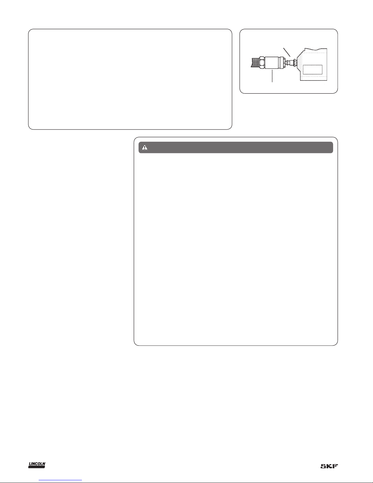
eyes. Always disconnect air coupler from
pump when the pump is not being used.
Air nipple
Pump
Air coupler
Specifications
Air motor effective diameter 2.5 in. (63,5 mm)
Air inlet
1
/4 in. NPTF
Material outlet
1
/4 in. NPTF
Ratio 50:1
Delivery output 80 in.³/min. (1 310 cm³/min)
Delivery 0.35 in.³.min. (5,7 cm³)
Minimum air pressure 30 psi (2 bar)
Maximum air pressure 150 psi (10 bar)
Maximum output pressure 7500 psi (517 bar)
Noise level at 120 psi (8 bar) <85 dB(A)
Failure to heed the following warnings
including misuse, over pressurizing,
modifying parts, using incompatible
chemicals and fluids, or using worn or
damaged parts, may result in equipment damage and/or serious personal
injury, fire, explosion, or property
damage.
• Do not exceed the stated maximum
working pressure of the pump, or of
the lowest rated component in your
system.
• Do not alter or modify any part of this
equipment.
• Do not operate this equipment with
combustible gas.
• Do not attempt to repair or disassem-
ble the equipment while the system is
pressurized.
• Make sure all grease connections are
securely tightened before using this
equipment.
WARNING
• Always read and follow the grease manufacturers recommendations regarding
grease compatibility, and the use of protective clothing and equipment.
• Check all equipment regularly and repair
or replace worn or damaged parts
immediately.
• Never point the dispensing valve at any
part of the body or at another person.
• Never try to stop or deflect material from
dispensing valve or leading connection or
component with your hand or body.
• Always check equipment for proper operation before each use, making sure
safety devices are in place and operating
properly.
• Always follow the pressure relief procedure after shutting off the pump, when
checking or servicing any part of the system, and when installing, cleaning or
changing any part of the system.
2
Installation
Typical drum and pail hookups are described
as follows only as a guide in selecting and
installing a system.
Contact a Lincoln factory representative
for assistance in designing a system for a
specific requirement.
Typical system hookup
Determine the drum or pail system for your
requirement.
Obtain an air line filter/regulator/lubricator to use with the inlet air supply and the
correct sized air and grease lines hoses with
any required reducers, connectors and
accessories.
Clean/flush the supply lines, hoses,
reducers, connectors and accessories with
mineral spirits or oil based solvent to purge
any contaminants such as dirt, moisture, or
metal shavings that could damage the pump
or system compo nents. Blow dry with air.
• Clean/flush the pump with mineral spirits
or oil based solvents if neces sary.
• Assemble the cleaned pump and supply
line together with any required accessory.
• Mount the assembled pump to the drum
or pail.
• Connect the material output line/hose to
the pump.
• Connect the air regulator to the pump.
• Make sure all connections are securely
tightened.
Do not flush pump with solvents without pump being grounded.
Splashing or static sparking when
flushing the pump with solvents can
cause an explosion.
Always hold a metal part of dispensing valve firmly to side of a grounded
metal pail and operate pump at lowest
possible fluid pressure.
Failure to comply may result in death
or serious injury.
WARNING
Do not exceed maximum working
pressure of lowest rated component
in system.
Pump can develop 7,500 psi
(517 bar) working pressure at 150 psi
(10 bar) maximum incoming air
pressure. All system equipment and
accessories must be rated to withstand
maximum working pressure of pump.
Failure to comply may result in death
or serious injury.
WARNING
Do not exceed 90 PSI (6 bar) air pres-
sure to pump when using whip’ hoses
Accessory item whip hoses for dispensing valve are rated at 4,500 psi
(310 bar).
Failure to comply may result in
serious injury or death.
WARNING
Accessories
• Filter/regulator/lubricator and gauge.
• Eyebolt kit.
• Follower plate - 120 lb., 400 Lb.
(54.4 kg, 181,4)
• Drum cover - 120 lb., 400 Lb.
(54.4 kg, 181,4)
• Drum cover with tie rods.
• 1709 Hoist.
Pressure relief
procedure
Always perform this procedure when the
pump is shut off and before checking, servicing, installing, cleaning or repairing any
part of this system.
Perform the following procedure:
1 Disconnect the air supply to the pump.
2 Point the dispensing valve away from
yourself and others.
3 Open the dispensing valve into an appro-
priate container until the pressure is
relieved.
If the above procedure does not relieve
the pressure, the dispensing valve or hose
may be restricted. To relieve the pressure,
very slowly loosen the hose end coupling.
Then loosen completely and clear the
dispensing valve and/or hose.
Operation
Inspection before using pump
Prior to operation or maintenance a visual
inspection shall be made. Check pump
system for leaks, worn or missing parts.
Any pump that appears to be damaged in
any way, is badly worn or operates abnormally shall be removed from use until
repairs are made. Contact a factory authorized service center for repairs.
If over pressurizing of the equipment is
believed to have occurred, contact a factory
authorized service center for inspection of
the pump.
Annual inspection by a factory authorized
service center is recommended.
!
Notice
Pump was tested in lightweight oil
and was left in to prevent corrosion.
Flush pump before connecting to
system to prevent possible contamination of grease being pumped.
3
To start pump, turn on the main air supply.
Slowly open the air regulator. Regulate air
pressure from 20 to 40 psi (1,3 to 2,7 Nm)
and throttle to prime pump. Open the dispensing valve to allow air to be purged from
the system. Allow pump to cycle until grease
without air pockets flows from dispensing
valve, then close dispensing valve.
After pump is primed, adjust air pressure
to achieve a smooth flow of grease from the
dispensing valve. Do not allow pump to
operate when out of material. Pump will
accelerate quickly and run too fast, resulting
in costly damage to the pump.
If the pump accelerates quickly or is running too fast, stop it immediately. Check the
grease supply and refill it if necessary.
Prime the pump to remove all air from the
system, or flush the pump and relieve
pressure.
In a circulating system, the pump runs
continuously and slows down or speeds up
as supply demands, until the air supply is
shut off.
In a direct supply system, with adequate
air pressure supplied to the motor, the pump
starts when the gun or dispensing valve is
opened and stalls against pressure when it
is closed.
Use the air regulator to control pump
speed and grease pressure. Always use the
lowest pressure required to achieve the
desired results. Higher pressures will cause
pump packing to wear prematurely.
Lubrication
An air line filter/regulator/lubricator is recommended for use with your Lincoln pump
to remove harmful dirt and moisture from
your compressor air supply, and to provide
automatic air motor lubrication.
If an air line lubricator is not used, the
following procedure should be per formed
daily:
1 Disconnect air coupler from air fitting.
2 Fill air coupler with 10 SAE motor oil and
reconnect to air fitting.
3 Operate pump to distribute lubricant.
Material restriction
prevention
Flush the system as required with a
compatible solvent to prevent material
buildup, when pumping material that will
dry or harden.
To prevent water or air corrosion, never
leave the pump filled with water or air.
Flush the pump first with a compatible solvent and then again with mineral spirits or
oil based solvent.
Do not operate pump or system with
pressure applied. Perform pressure
relief procedure prior to starting pump.
Failure to comply may result in death
or serious injury.
WARNING
Maintenance
Do not perform maintenance on pump
or system with pressure applied
Failure to comply may result in death
or serious injury.
WARNING
Do not flush pump with solvents without pump being grounded.
Splashing or static sparking when
flushing the pump with solvents can
cause an explosion.
Always hold a metal part of dispensing valve firmly to side of a grounded
metal pail and operate pump at lowest
possible fluid pressure.
Failure to comply may result in death
or serious injury.
WARNING
Corrosion prevention
Do not disassemble or assemble pump
with pressure applied to pump or
system.
Relieve all pressure from system
before and after use of pump.
Failure to comply may result in death
or serious injury.
WARNING
4
 Loading...