

Lincoln IDEALARC DC-1000 Operator's Manual

Operator’s Manual
®
IDEALARC
DC-1000
For use with machines having Code Numbers:
12480
Register your machine:
www.lincolnelectric.com/register
Authorized Service and Distributor Locator:
www.lincolnelectric.com/locator
Save for future reference
Date Purchased
Code: (ex: 10859)
Serial: (ex: U1060512345)
IM10212 | Issue D ate Sept-15
© Lincoln Global, Inc. All Rights Reserved.
Need Help? Call 1.888.935.3877
to talk to a Service Representative
Hours of Operation:
8:00 AM to 6:00 PM (ET) Mon. thru Fri.
After hours?
Use “Ask the Experts” at lincolnelectric.com
A Lincoln Service Representative will contact you
no later than the following business day.
For Service outside the USA:
Email: globalservice@lincolnelectric.com
THANK YOU FOR SELECTING
A QUALITY PRODUCT BY
LINCOLN ELEC TRIC.
PLEASE EXAMINE CARTON AND EQUIPMENT FOR
DAMAGE IMMEDIATELY
When this equipment is shipped, title passes to the purchaser
upon receipt by the carrier. Consequently, claims for material
damaged in shipment must be made by the purchaser against the
transportation company at the time the shipment is received.
SAFETY DEPENDS ON YOU
Lincoln arc welding and cutting equipment is designed and built
with safety in mind. However, your overall safety can be increased
by proper installation ... and thoughtful operation on your part.
DO NOT INSTALL, OPERATE OR REPAIR THIS EQUIPMENT
WITHOUT READING THIS MANUAL AND THE SAFETY
PRECAUTIONS CONTAINED THROUGHOUT. And, most importantly,
think before you act and be careful.
This statement appears where the information must be followed
exactly to avoid serious personal injury or loss of life.
This statement appears where the information must be followed
to avoid minor personal injury or damage to this equipment.
KEEP YOUR HEAD OUT OF THE FUMES.
DON’T get too close to the arc.
Use corrective lenses if necessary
to stay a reasonable distance
away from the arc.
READ and obey the Safety Data
Sheet (SDS) and the warning label
that appears on all containers of
welding materials.
USE ENOUGH VENTILATION or
exhaust at the arc, or both, to
keep the fumes and gases from
your breathing zone and the general area.
IN A LARGE ROOM OR OUTDOORS, natural ventilation may be
adequate if you keep your head out of the fumes (See below).
USE NATURAL DRAFTS or fans to keep the fumes away
from your face.
If you de velop unusual symptoms, see your supervisor.
Perhaps the welding atmosphere and ventilation system
should be checked.
WEAR CORRECT EYE, EAR &
BODY PROTECTION
PROTECT your eyes and face with welding helmet
properly fitted and with proper grade of filter plate
(See ANSI Z49.1).
PROTECT your body from welding spatter and arc
flash with protective clothing including woolen
clothing, flame-proof apron and gloves, leather
leggings, and high boots.
PROTECT others from splatter, flash, and glare
with protective screens or barriers.
IN SOME AREAS, protection from noise may be appropriate.
BE SURE protective equipment is in good condition.
Also, wear safety glasses in work area
AT ALL TIMES.
SPECIAL SITUATIONS
DO NOT WELD OR CUT containers or materials which previously
had been in contact with hazardous substances unless they are
properly cleaned. This is extremely dangerous.
DO NOT WELD OR CUT painted or plated parts unless special
precautions with ventilation have been taken. They can release
highly toxic fumes or gases.
Additional precautionary measures
PROTECT compressed gas cylinders from excessive heat,
mechanical shocks, and arcs; fasten cylinders so they cannot fall.
BE SURE cylinders are never grounded or part of an
electrical circuit.
REMOVE all potential fire hazards from welding area.
ALWAYS HAVE FIRE FIGHTING EQUIPMENT READY FOR
IMMEDIATE USE AND KNOW HOW TO USE IT.
WARNING
CAUTION
Safety 01 of 04 - 5/16/2018
SECTION A:
WARNINGS
CALIFORNIA PROPOSITION 65 WARNINGS
WARNING: Breathing diesel engine exhaust
exposes you to chemicals known to the State
of California to cause cancer and birth defects,
or other reproductive harm.
• Always start and operate the engine in a
well-ventilated area.
• If in an exposed area, vent the exhaust to the outside.
• Do not modify or tamper with the exhaust system.
• Do not idle the engine except as necessary.
For more information go to
www.P65 warnings.ca.gov/diesel
WARNING: This product, when used for welding or
cutting, produces fumes or gases which contain
chemicals known to the State of California to cause
birth defects and, in some cases, cancer. (California
Health & Safety Code § 25249.5 et seq.)
WARNING: Cancer and Reproductive Harm
www.P65warnings.ca.gov
ARC WELDING CAN BE HAZARDOUS. PROTECT
YOURSELF AND OTHERS FROM POSSIBLE SERIOUS
INJURY OR DEATH. KEEP CHILDREN AWAY.
PACEMAKER WEARERS SHOULD CONSULT WITH
THEIR DOCTOR BEFORE OPERATING.
Read and understand the following safety highlights. For
additional safety information, it is strongly recommended
that you purchase a copy of “Safety in Welding & Cutting ANSI Standard Z49.1” from the American Welding Society,
P.O. Box 351040, Miami, Florida 33135 or CSA Standard
W117.2-1974. A Free copy of “Arc Welding Safety” booklet
E205 is available from the Lincoln Electric Company,
22801 St. Clair Avenue, Cleveland, Ohio 44117-1199.
BE SURE THAT ALL INSTALLATION, OPERATION,
MAINTENANCE AND REPAIR PROCEDURES ARE
PERFORMED ONLY BY QUALIFIED INDIVIDUALS.
FOR ENGINE POWERED
EQUIPMENT.
1.a. Turn the engine off before troubleshooting
and maintenance work unless the
maintenance work requires it to be running.
1.b. Operate engines in open, well-ventilated areas or vent the engine
exhaust fumes outdoors.
1.c. Do not add the fuel near an open flame welding
arc or when the engine is running. Stop the
engine and allow it to cool before refueling to
prevent spilled fuel from vaporizing on contact
with hot engine parts and igniting. Do not spill fuel when filling
tank. If fuel is spilled, wipe it up and do not start engine until
fumes have been eliminated.
1.d. Keep all equipment safety guards, covers
and devices in position and in good repair.
Keep hands, hair, clothing and tools away
from V-belts, gears, fans and all other
moving parts when starting, operating or
repairing equipment.
1.e. In some cases it may be necessary to remove safety guards to
perform required maintenance. Remove guards only when
necessary and replace them when the maintenance requiring
their removal is complete. Always use the greatest care when
working near moving parts.
1.f. Do not put your hands near the engine fan. Do not attempt to
override the governor or idler by pushing on the throttle control
rods while the engine is running.
1.g. To prevent accidentally starting gasoline engines while turning
the engine or welding generator during maintenance work,
disconnect the spark plug wires, distributor cap or magneto wire
as appropriate.
1.h. To avoid scalding, do not remove the radiator
pressure cap when the engine is
hot.
ELECTRIC AND
MAGNETIC FIELDS MAY
BE DANGEROUS
2.a. Electric current flowing through any conductor
causes localized Electric and Magnetic Fields (EMF).
Welding current creates EMF fields around welding cables
and welding machines
2.b. EMF fields may interfere with some pacemakers, and
welders having a pacemaker should consult their physician
before welding.
2.c. Exposure to EMF fields in welding may have other health effects
which are now not known.
2.d. All welders should use the following procedures in order to
minimize exposure to EMF fields from the welding circuit:
2.d.1. Route the electrode and work cables together - Secure
them with tape when possible.
2.d.2. Never coil the electrode lead around your body.
2.d.3. Do not place your body between the electrode and work
cables. If the electrode cable is on your right side, the
work cable should also be on your right side.
2.d.4. Connect the work cable to the workpiece as close as possible to the area being welded.
2.d.5. Do not work next to welding power source.
SAFETY
Safety 02 of 04 - 5/16/2018
ELECTRIC SHOCK
CAN KILL.
3.a. The electrode and work (or ground) circuits are
electrically “hot” when the welder is on. Do
not touch these “hot” parts with your bare skin or wet clothing.
Wear dry, hole-free gloves to insulate hands.
3.b. Insulate yourself from work and ground using dry insulation.
Make certain the insulation is large enough to cover your full area
of physical contact with work and ground.
In addition to the normal safety precautions, if
welding must be performed under electrically
hazardous conditions (in damp locations or while
wearing wet clothing; on metal structures such as
floors, gratings or scaffolds; when in cramped
positions such as sitting, kneeling or lying, if there
is a high risk of unavoidable or accidental contact
with the workpiece or ground) use the following
equipment:
• Semiautomatic DC Constant Voltage (Wire) Welder.
• DC Manual (Stick) Welder.
• AC Welder with Reduced Voltage Control.
3.c. In semiautomatic or automatic wire welding, the electrode,
electrode reel, welding head, nozzle or semiautomatic welding
gun are also electrically “hot”.
3.d. Always be sure the work cable makes a good electrical
connection with the metal being welded. The connection should
be as close as possible to the area being welded.
3.e. Ground the work or metal to be welded to a good electrical (earth)
ground.
3.f. Maintain the electrode holder, work clamp, welding cable and
welding machine in good, safe operating condition. Replace
damaged insulation.
3.g. Never dip the electrode in water for cooling.
3.h. Never simultaneously touch electrically “hot” parts of electrode
holders connected to two welders because voltage
between the
two can be the total of the open circuit voltage of both
welders.
3.i. When working above floor level, use a safety belt to protect
yourself from a fall should you get a shock.
3.j. Also see It ems 6.c. and 8.
ARC RAYS CAN BURN.
4.a. Use a shield with the proper filter and cover plates to protect your
eyes from sparks and the rays of the arc when welding or
observing open arc welding. Headshield and filter lens should
conform to ANSI Z87. I standards.
4.b. Use suitable clothing made from durable flame-resistant material
to protect your skin and that of your helpers from the arc rays.
4.c. Protect other nearby personnel with suitable, non-flammable
screening and/or warn them not to watch the arc nor expose
themselves to the arc rays or to hot spatter or metal.
FUMES AND GASES
CAN BE DANGEROUS.
5.a. Welding may produce fumes and gases
hazardous to health. Avoid breathing these
fumes and gases. When welding, keep your head out of the fume.
Use enough ventilation and/or exhaust at the arc to keep fumes
and gases away from the breathing zone. When welding
hardfacing (see instructions on container or SDS)
or on lead or cadmium plated steel and other
metals or coatings which produce highly toxic
fumes, keep exposure as low as possible and
within applicable OSHA PEL and ACGIH TLV limits
using local exhaust or mechanical ventilation
unless exposure assessments indicate otherwise.
In confined spaces or in some circumstances,
outdoors, a respirator may also be required.
Additional precautions are also required when
welding
on galvanized steel.
5. b. The operation of welding fume control equipment is affected by
various factors including proper use and positioning of the
equipment, maintenance of the equipment and the specific
welding procedure and application involved. Worker exposure
level should be checked upon installation and periodically
thereafter to be certain it is within applicable OSHA PEL and
ACGIH TLV limits.
5.c. Do not weld in locations near chlorinated hydrocarbon vapors
coming from degreasing, cleaning or spraying operations. The
heat and rays of the arc can react with solvent vapors to form
phosgene, a highly toxic gas, and other irritating products.
5.d. Shielding gases used for arc welding can displace air and
cause
injury or death. Always use enough ventilation, especially in
confined areas, to insure breathing air is safe.
5.e. Read and understand the manufacturer’s instructions for this
equipment and the consumables to be used, including the
Safety Data Sheet (SDS) and follow your employer’s safety
practices. SDS forms are available from your welding
distributor or from the manufacturer.
5.f. Also see item 1.b.
SAFETY
Safety 03 of 04 - 5/16/2018
WELDING AND CUTTING
SPARKS CAN CAUSE
FIRE OR EXPLOSION.
6.a. Remove fire hazards from the welding area. If
this is not possible, cover them to prevent the welding sparks
from starting a fire. Remember that welding sparks and hot
materials from welding can easily go through small cracks and
openings to adjacent areas. Avoid welding near hydraulic lines.
Have a fire extinguisher readily available.
6.b. Where compressed gases are to be used at the job site, special
precautions should be used to prevent hazardous situations.
Refer to “Safety in Welding and Cutting” (ANSI Standard Z49.1)
and the operating information for the equipment being used.
6.c. When not welding, make certain no part of the electrode circuit is
touching the work or ground. Accidental contact can cause
overheating and create a fire hazard.
6.d. Do not heat, cut or weld tanks, drums or containers until the
proper steps have been taken to insure that such procedures
will not cause flammable or toxic vapors from substances inside.
They can cause an explosion even though they have been
“cleaned”. For information, purchase “Recommended Safe
Practices for the Preparation for Welding and Cutting of
Containers and Piping That Have Held Hazardous Substances”,
AWS F4.1 from the American Welding Society
(see address above).
6.e. Vent hollow castings or containers before heating, cutting or
welding. They may explode.
6.f. Sparks and spatter are thrown from the welding arc. Wear oil free
protective garments such as leather gloves, heavy shirt, cuffless
trousers, high shoes and a cap over your hair. Wear ear plugs
when welding out of position or in confined places. Always wear
safety glasses with side shields when in a welding area.
6.g. Connect the work cable to the work as close to the welding area
as practical. Work cables connected to the building framework or
other locations away from the welding area increase the
possibility of the welding current passing through lifting chains,
crane cables or other alternate circuits. This can create fire
hazards or overheat lifting chains or cables until they fail.
6.h. Also see item 1.c.
6.I. Read and follow NFPA 51B “Standard for Fire Prevention During
Welding, Cutting and Other Hot Work”, available from NFPA, 1
Batterymarch Park, PO box 9101, Quincy, MA 022690-9101.
6.j. Do not use a welding power source for pipe thawing.
CYLINDER MAY EXPLODE IF
DAMAGED.
7.a. Use only compressed gas cylinders containing
the correct shielding gas for the process used
and properly operating regulators designed for
the gas and pressure used. All hoses, fittings,
etc. should be suitable for the application and
maintained in good condition.
7.b. Always keep cylinders in an upright position securely chained to
an undercarriage or fixed support.
7.c. Cylinders should be located:
• Away from areas where they may be struck or subjected
to physical damage.
• A safe distance from arc welding or cutting operations
and any other source of heat, sparks, or flame.
7.d. Never allow the electrode, electrode holder or any other
electrically “hot” parts to touch a cylinder.
7.e. Keep your head and face away from the cylinder valve outlet
when opening the cylinder valve.
7.f. Valve protection caps should always be in place and hand tight
except when the cylinder is in use or connected for use.
7.g. Read and follow the instructions on compressed gas cylinders,
associated equipment, and CGA publication P-l, “Precautions for
Safe Handling of Compressed Gases in Cylinders,” available from
the Compressed Gas Association, 14501 George Carter Way
Chantilly, VA 20151.
FOR ELECTRICALLY
POWERED EQUIPMENT.
8.a. Turn off input power using the disconnect
switch at the fuse box before working on
the equipment.
8.b. Install equipment in accordance with the U.S. National Electrical
Code, all local codes and the manufacturer’s recommendations.
8.c. Ground the equipment in accordance with the U.S. National
Electrical Code and the manufacturer’s recommendations.
Refer to
http://www.lincolnelectric.com/safety
for additional safety information.
SAFETY
Safety 04 of 04 - 5/16/2018

TABLE OF CONTENTS
Page
Installation.......................................................................................................................Section A
Technical Specifications.......................................................................................................A-1
Safety Precautions...............................................................................................................A-2
Location ........................................................................................................................A-2
Stacking ........................................................................................................................A-2
Input Wiring ...................................................................................................................A-2
Reconnect Procedures..................................................................................................A-3
Output Connections..............................................................................................................A-4
_______________________________________________________________________________
Operation.........................................................................................................................Section B
Safety Precautions ...............................................................................................................B-1
Product Description ..............................................................................................................B-1
Meaning of Symbols .............................................................................................B-1 thru B-3
To Set Polarity......................................................................................................................B-4
Set-Up For Various Procedures....................................................................................B-4, B-5
________________________________________________________________________________
Maintenance ....................................................................................................Section D
Safety Precautions ...................................................................................................D-1
General Maintenance .........................................................................................D-1
________________________________________________________________________
Troubleshooting ..............................................................................................Section E
Safety Precautions ................................................................................................E-1
How to Use Troubleshooting Guide.......................................................................E-1
Troubleshooting Guide ............................................................................E-2 thru E-7
________________________________________________________________________
Connection and Wiring Diagrams..................................................................Section F
________________________________________________________________________
Parts List ........................................................................................................parts.lincolnelectric.com
Overload Protection ...........................................................................................D-1
66
Content/details may be changed or updated without notice. For most current Instruction Manuals, go to
parts.lincolnelectric.com.
________________________________________________________________________

7
NOTES
7
IDEALARC® DC-1000

A-1
INSTALLATION
TECHNICAL SPECIFICATIONS – Idealarc®DC-1000
INPUT: THREE PHASE ONLY
INPUT AC
OLTAGE (U1)
V
380V
MS
R
440V
MS
R
FREQUENCY
I
AT 1250A 44V 50%DC I
MAX
1
50/60Hz 139A
50/60Hz 120A
AC INPUT CURRENT (I
MS
R
MS
R
1
MAX
RATED OUTPUTS (ALL MODES)
1)
DUTY CYCLE
(
(X) DC AMPS
AVG
MAXIMUM 50% 1250 (I2) 44 (U2)
60% 1140 (I2) 44 (U2)
100% 1000 (I2) 44 (U2)
MINIMUM 100% 150 21.5
ADDITIONAL OUTPUTS (ALL MODES)
DUTY CYCLE
(1)
(X) DC AMPS
VG
A
MAXIMUM 45% 1300 46
MINIMUM 100% 150 16
OCV VOLTAGE AND AUXILIARY POWER
PEAK OPEN CIRCUIT (NO-LOAD) DC VOLTAGE (U0) AC AUXILIARY POWER
, I
) AT RATED OUTPUT (I2, U2)
MAX
EFF
1
1
AT 1140A 44V 60%DC I
128A
MS
R
111A
MS
R
AT 1000A 44V 100%DC
FF
E
116A
MS
R
100A
MS
R
DC VOLTS
DC VOLTS
AVG
A
VG
A-1
CV SUBMERGED ARC: 78V
CV INNERSHIELD: 78V
115 VOLTS
8 AMPS
RMS
RMS
CC SUBMERGED ARC: 78V
RECOMMENDED INPUT WIRE AND FUSE SIZES FOR MAXIMUM RATED OUTPUT.
IN ADDITION, FOLLOW LATEST NATIONAL ELECTRICAL CODE AND LOCAL CODE.
INPUT
AC VOLTAGE
(U1)
380V
RMS
440V
RMS
MAXIMUM
FREQUENCY
EFFECTIVE INPUT
CURRENT
50/60HZ 116A
50/60HZ 100A
(I
1EFF
RMS
RMS
TYPE 90°C COPPER
)
WIRE IN CONDUIT
AWG (mm2)
COPPER GROUND
WIRE IN CONDUIT
AWG (mm2)
BUSSMANN LIMITRON FUSE SIZE AND
FUSE SIZE CATALOG NUMBER
2 (35) 6 (16) 175A KTS-R-175
3 (25) 6 (16) 150A KTS-R-150
PHYSICAL DIMENSIONS
HEIGHT WIDTH DEPTH WEIGHT
30.75 IN.
781 MM
22.25 IN.
565 MM
39.0 IN.
991 MM
821 LBS
372 KG.
TEMPERATURE RANGES
OPERATING TEMPERATURE RANGE STORAGE TEMPERATURE RANGE
14º F TO 104º F (-10º C TO +40º C) -40º F TO 140º F (-40º C TO +60º C)
INSULATION CLASS
TRANSFORMER CHOKE
CATALOG NUMBER
(2)
CLASS F (155º C) CLASS F (155º C)
CCC, CE, IP21S, IEC60974-1, IEC60974-10, GB 15579.1-2013, C-TICK
(1)
Based upon 10 minute time period (for 100% duty cycle, it is 10 minutes on and 0 minutes off).
(2)
Use only Bussmann Limitron fuses specified. Other fuses may not protect the welder and may cause overheating and possible fire damage.
STANDARDS COMPLIANCE
A-2
INSTALLATION
A-2
SAFETY PRECAUTIONS
ead this entire installation section before you
R
start installation.
WARNING
ELECTRIC SHOCK can kill.
Only qualified personnel should
•
perform this installation.
• Turn the input power OFF at the
disconnect switch or fuse box
before working on this equipment.
Turn off the input power to any
other equipment connected to the
welding system at the disconnect
switch or fuse box before working
on the equipment.
• Do not touch electrically hot parts.
• Always connect the grounding lug (located
inside the reconnect input access door) to a
proper safety (Earth) ground.
-----------------------------------------------------------------------
LOCATION
Even though the machine is designed to operate
under a wide variety of environmental conditions, for
maximum reliability and long life the machine should
be located in a clean, dry place where there is free
circulation of clean air in through the front and out the
back of the machine. Dirt and dust that can be drawn
into the machine should be kept to a minimum. Failure
to observe these precautions can result in excessive
operating temperatures and nuisance shutdown of the
machine.
The case front incorporates a recessed control panel
which protects the controls and minimizes the possibilities of accidental contact. This cover panel can be
flipped open to permit access to the enclosed control
section.
The individual case sides are removable for easy
access for internal service or inspection.
The case rear is equipped with a removable cover
plate, permitting easy access to the input panel.
The machine uses a 38” (965mm) long base. The low
profile case facilitates installation of the machine
under a workbench and stacking the machines two
high to conserve floor space.
A permanent lifting eye is located at the top of the
machine and is positioned so that it acts as nearly as
possible through the center of gravity. This lift eye fits
under the case of the second machine without interference when stacking.
This equipment is for industrial use only and it is not
intended for use in residential locations where the
electrical power is provided by the public low-voltage
supply system. There can be potential difficulties in
residential locations due to conducted as well as radiated radio-frequency disturbances. The EMC or RF
classification of this equipment is Class A.
TACKING
S
WARNING
FALLING EQUIPMENT can cause
injury.
• Do not lift this machine using lift bale if
it is equipped with a heavy accessory
such as trailer or gas cylinder.
• Lift only with equipment of adequate lifting capacity.
• Be sure machine is stable when lifting.
• Do not stack more than two high.
• Do not stack the DC-1000 on top of any other
machine.
---------------------------------------------------------------------
Two DC-1000’s may be stacked by observing the
following safety precautions:
1. Make sure the first or bottom unit is setting on a
level, well-supported surface.
2. The units must be stacked with their fronts flush,
making sure the two holes in the base rails of the
top unit are over the two pins located on top of the
bottom unit.
INPUT WIRING
Be sure the voltage, phase and frequency of the input
power is as specified on the welder nameplate.
Dual voltage (e.g. 380/440) models are shipped
connected for the highest voltage. To change the
connection, see the connection diagram pasted to the
inside of the access panel in the case back.
Have a qualified electrician remove the rear access
panel and connect 3 phase AC power to terminals L1,
L2and L3of the input panel in accordance with the
U.S. National Electrical Code, all local codes and the
wiring diagram located inside the machine.
The welder frame must be grounded. A stud marked
with the symbol located inside the machine near
the input panel is provided for this purpose. See the
U.S. National Electrical Code for details on proper
grounding methods. See Technical Specifications for
recommended input wire and fuse sizes.
IDEALARC® DC-1000
A-3
INPUT
LINES
H1
H3
L3
LI
L2
{
H2
H4
}
TAPE
INPUT
LINES
H
1
H4
L3
LI
L2
{
H
2
H
3
}
TAPE
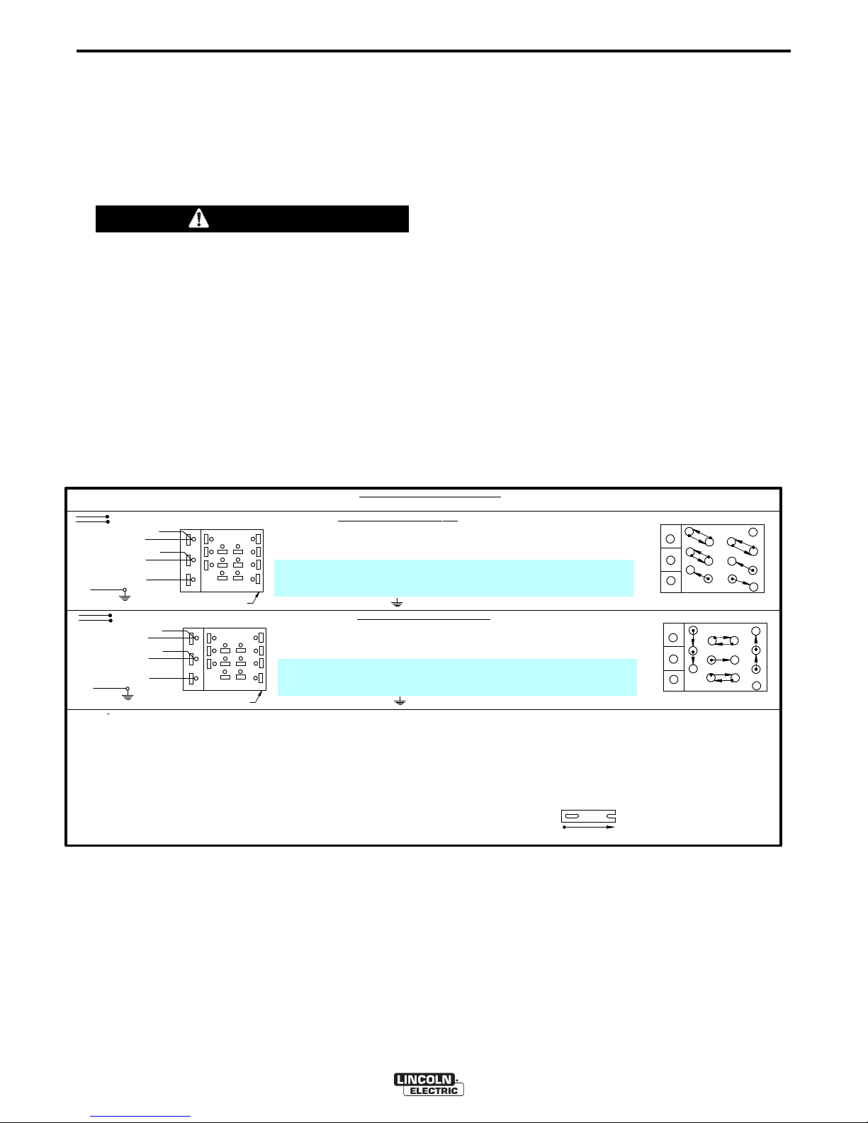
INPUT SUPPLY
CONNECTION DIAGRAM
WARNING: ALL INPUT POW ER MUS T BE ELECTRICALLY DISCONNECTED BEFORE TOUCHING PANEL. NOTE: MACHINES ARE SHIPPED FROM FACTORY CONNECTED FOR HIGHEST VOLTAGE.
RECONNECT PANEL
GND
CONNECTION FOR 440VOLTS 50 / 60 Hz.
1.
O
N RECONNECT PANEL, LOOSEN ALL HEX BOLTS OR NUTS, PULL BACK MOVABLE LINKS, AND
ROTATE LINKS TO THEIR NEW POSITIONS. POSITION EACH LINK BETW EEN THE WIRE TERMINAL
A
ND HEX BOLT OR NUT, PUSH THE LINK COMPLETELY FORWA RD, SECURELY TIGHTEN ALL HEX
BOLTS OR NUTS. DO NOT REMOVE HEX BOLTS OR NUTS AT A NY TIME.
CONNECT TERMINAL MARKED TO GROUND PER NATIONAL ELECT RICAL CODE.
4.
3
.
2.
L
INK POSITIONS
RECONNECT PANEL
GND
CONNECTIO
N FOR 380 VOLTS 50
/ 60 Hz.
1.
O
N RECONNECT PANEL, LOOSEN ALL HEX BOLTS OR NUTS, PULL BACK MOVABLE LINKS, AND
ROTATE LINKS TO THEIR NEW POSITIONS. POSITION EACH LINK BET WEEN THE WIRE T ERMINAL
AND HEX BOLT OR NUT, PUSH THE LINK COMPLETELY FORWA RD, SECURELY TIGHTEN ALL HEX
BOLTS OR NUTS. DO NOT REMOVE HEX BOLTS OR NUTS AT A NY TIME.
4.
3.
2.
LINK POSITIONS
MOVABLE LINK POSITIONS INDICATED
BY ARROWED LINE
CONNECT TERMINAL MARKED TO GROUND PER NATIONAL ELECT RICAL CODE.
INSULATE THE UNUSED H2 & H4 LEAD TERMINALS
SEPARATELY
TO PROVIDE AT LEAST
600V. INSULATION.
CONNECT L1, L2 & L3 INPUT SUPPLY LINES & H1 & H3 CONTROL TRANSFORMER LEADS TO INPUT
TERMINALS AS SHOWN.
CONNECT L1, L2 & L3 INPUT SUPPLY LINES & H1 & H4 CONTROL TRANSFORMER LEADS TO INPUT
TERMINALS AS SHOWN.
INSULATE THE UNUSED H2 & H3 LEAD TERMINALS SEPARATELY TO PROVIDE AT LEAST
600V. INSULATION.
C
M14358-1
INSTALLATION
RECONNECT PROCEDURE
Multiple voltage machines are shipped connected for
the highest input voltage listed on the machine’s rating
plate. Before installing the machine, check that the
Reconnect Panel in the Input Box Assembly is
connected for the proper voltage.
A-3
o reconnect a multiple voltage machine to a different
T
voltage, remove input power and change the position
of the reconnect board on the Reconnect Panel.
Follow The Input Connection Diagram located on the
inside of Case Back Input Access Door. These
connection diagrams for the following codes are listed
elow.
b
CAUTION
Failure to follow these instructions can cause
immediate failure of components within the
machine.
When powering welder from a generator be sure
to turn off welder first, before generator is shut
down, in order to prevent damage to the welder.
-----------------------------------------------------------------------------------------------------
-
FIGURE 1
1. For 380/440, see Figure 1, (M14358-1).
2. For Voltages not listed, see the Input Connection
Diagram pasted on the inside of the Case
Back Input Access Door.
IDEALARC® DC-1000

A-4
INSTALLATION
A-4
OUTPUT CONNECTIONS
Output Studs
The output leads are connected to the output
terminals. The output terminals are located on the
lower case front and labeled “+” and “-”. There are
1000 amp rated “+” terminals on the right side, one
500 amp rated “+” terminal near the center and “-”
terminals on the left side. They are fully recessed to
minimize the possibility of accidental contact by an
object or a person. Strain relief is provided by the
oval holes in the base. The leads are run through
these oval holes before they are connected to the
output terminals.
An output stud cover protects against accidental
contact with the output studs. Cover hinges upward
for access to the studs.
The 1000 amp output connections provide the full
rated output range of the machine. See Table1 for
recommended DC-1000 cable sizes for combined
lengths of electrode and work cables.
The 500 amp output connections provide enhanced
lower current arc characteristics, especially for
submerged arc and GMAW procedures below
450 amps.
Control Cable Connection
erminal strips with screw connections are located
T
behind the hinged door on the front of the power
source to make all the control cable connections for
operating wire feeding equipment. See the
appropriate connection diagram for exact instructions
covering the wire feeder being used.
With the DC-1000 turned off, the control cable from
the automatic wire feeding equipment is connected to
the terminal strip. A strain relief box connector is
provided for access into the terminal strip section. A
chassis grounding screw is also provided below the
terminal strip marked with the symbol for
connecting the wire feeding equipment grounding
wire. See the appropriate connection diagram for the
exact instructions for the wire feeder being used. A
spare hole is provided for an additional box connector
if required.
Connecting for Air Carbon Arc:
a. Turn off all power.
b. Disconnect all wire feed unit control, electrode and
work leads.
c. Connect a jumper from 2-4 on terminal strip.
d. Place mode switch in the CV Innershield position.
Auxiliary Power
This machine supplies the 115 volt, AC power needed
for operating wire feeding equipment. The power is
available from terminals #31 and #32 on the terminal
strip. An 8 amp slow blow fuse on the machine control
panel protects the auxiliary power from excessive
overloads. The circuit has a 1000 volt-ampere rating.
TABLE 1
DC-1000 Cable Sizes for Combined Lengths of Copper Electrode and Work Cable
at 100% Duty Cycle
Lengths up to 150 ft. (46m)
With the DC-1000 connected for air carbon arc
welding, the output terminals will be energized at all
times.
Cable SizeParallel CablesCable Length
2
1/0 (53mm
3
2/0 (67mm
)3
2
)150 ft.(46m) to 200 ft (61m)
3
IDEALARC® DC-1000
3/0 (85mm
2
)200 ft.(61m) to 250 ft.(76m)
B-1
OPERATION
B-1
OPERATING INSTRUCTIONS
WARNING
ELECTRIC SHOCK can kill.
• Do not touch electrically live parts or
electrode with skin or wet clothing.
Insulate yourself from work and
•
ground.
• Always wear dry insulating gloves.
------------------------------------------------------------------------
FUMES AND GASES can be
dangerous.
• Keep your head out of fumes.
• Use ventilation or exhaust to remove
fumes from breathing zone.
------------------------------------------------------------------------
WELDING SPARKS can cause fire or
explosion.
• Keep flammable material away.
• Do not weld on closed containers.
------------------------------------------------------------------------
ARC RAYS can burn eyes and skin.
• Wear eye, ear and body
protection.
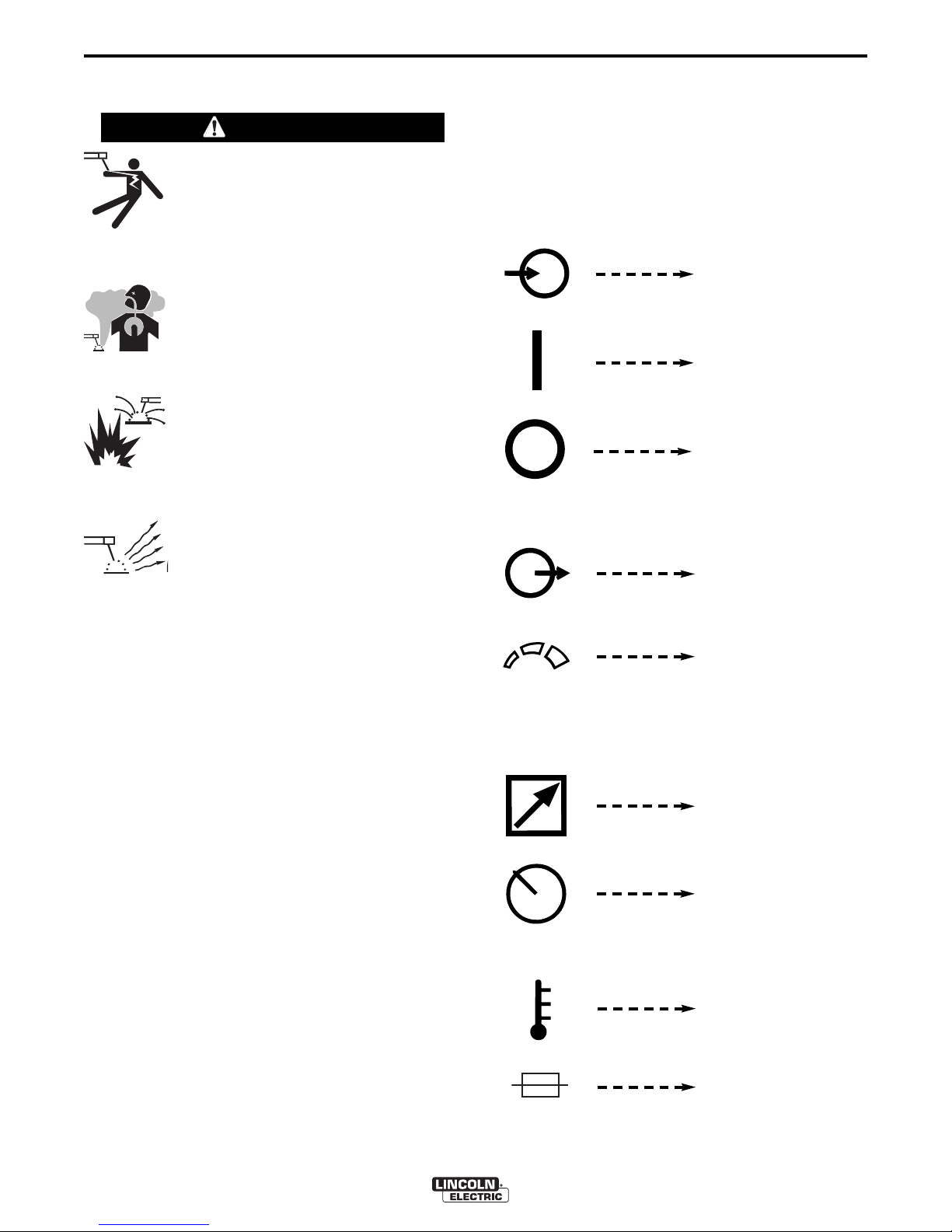
MEANINGS OF SYMBOLS
The DC-1000 nameplate has been designed to use
international symbols in describing the function of the
various components. Below are the symbols used.
OWER ON-OFF SWITCH
P
Input (Power)
On
Off
OUTPUT CONTROL DIAL
------------------------------------------------------------
See additional warning information at
front of this operator’s manual.
-----------------------------------------------------------
PRODUCT DESCRIPTION
The DC-1000 is an SCR-controlled three phase DC
power source. It is designed with a single range
potentiometer control for submerged arc or open arc
automatic and semiautomatic welding. It can be used
for air carbon arc cutting with carbon rods up to and
including 5/8” (15.9mm) dia. GMAW procedures can
be performed using the 500 amp output stud. This
connection provides the enhanced lower current arc
characteristics required for this type of welding.
The DC-1000 is provided with a three position mode
switch that selects CV Innershield®, CV Submerged
Arc or CC Submerged Arc.
The unit is designed to be used with the NA-5, NA-5R
and NA-3 automatics, the LT-56 and LT-7 tractors,
and can also be used with the LN-7, LN-8 or LN-9
semiautomatic wire feeders.
Output Control
Increase/Decrease of
Output (Voltage or
Current)
OUTPUT CONTROL PANEL-REMOTE SWITCH
Remote Output Voltage
or Current Control
Panel Output Voltage
or Current Control
THERMAL PROTECTION LIGHT
High Temperature
Fuse
IDEALARC® DC-1000
B-2
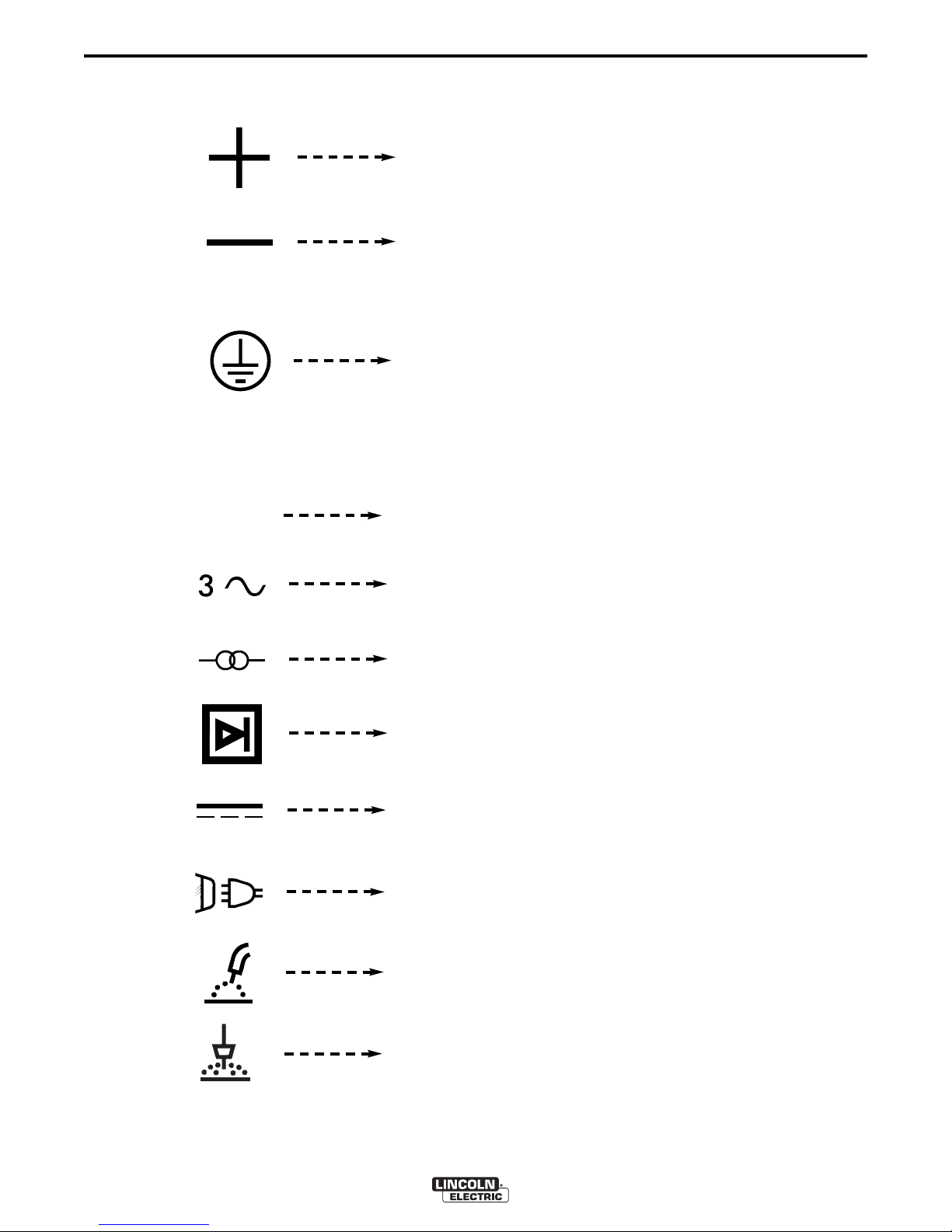
ELECTRODE POLARITY SWITCH
EARTH GROUND CONNECTION ON INPUT BOX
RATING PLATE
IEC 60974-1
OPERATION
ositive Electrode
P
Negative Electrode
Signifying the Earth
(Ground) Connection
Designates welder complies with International Electrotechnical
Commission requirements 60974-1.
B-2
Three Phase Power
Transformer
Rectifier
Rectified DC Output
Line Connection
Flux Cored Arc Welding
Submerged Arc Welding
IDEALARC®DC-1000

B-3
RATING PLATE
IP21S
CE
OPERATION
egree of protection provided by the enclosure
D
Designates welder complies with low voltage directive
and with EMC directive.
Designates welder complies with China Compulsory
Certificate
C-Tick symbol indicates conformity with Australian
EMC regulations.
B-3
-10 Class A
GB 15579.1-2013
U
0
U
1
U
2
I
1max
I
1eff
I
2
Designates welder complies with IEC 60974-10
Electromagnetic Capability (EMC) requirements for
equipment used in industrial locations.
Designates welder complies with Chinese National
Standard GB 15579.1-2013.
Rated peak no-load voltage (DC
Rated supply voltage (AC
Conventional load voltage (DC
Rated maximum supply current (AC
Maximum effective supply current (AC
Rated welding current (DC
rms
avg
).
).
peak
).
avg
).
rms
).
rms
).
X
Duty cycle (Based upon 10 minute time period).
IDEALARC®DC-1000

B-4
OPERATION
B-4
TO SET POLARITY
Turn off the DC-1000 and connect the electrode cable
to the “Positive” or “Negative” studs depending upon
he electrode polarity desired. Connect the work cable
t
to the other stud. (See “Output Connections”).
Set the “Electrode Negative-Electrode Positive” switch
to correspond to the polarity of the electrode cable
connection. This switch setting is necessary for proper
operation of some Lincoln wire feeders and does not
change the welding polarity.
Starting the Machine - The push button power “on”
switch at the extreme right side of the control panel
energizes and closes the three phase input contactor
from a 110 volt auxiliary transformer. This in turn
energizes the main power transformer.
The white light below the stop-start button indicates
when the input contactor is energized.
Output Control - The output control in the center of
the control panel is a continuous control of the machine
output. The control may be rotated from min. to max.
while under load to adjust the machine output.
The machine is equipped with line voltage
compensation as a standard feature. This will hold the
output relatively constant except at maximum output of
the machine, through a fluctuation of +/- 10% of input
line voltage.
Output Control at DC-1000 or Output Control
Remote Switch
The toggle switch on the control panel labeled
“Panel” / “Remote” gives the operator the option of
controlling the output at the machine control panel or at
a remote station. For remote control, the toggle switch
is set in the “Remote” position and controlled at the
wire feed unit control or by connecting a K775 control
to the appropriate terminals (as indicated on the
connection diagram) on the terminal strip at the front of
the machine. For control at the machine
control panel, the toggle switch is set in the “Panel”
position.
Mode Switch
The toggle switch labeled CV Innershield, CV
Submerged Arc, CC Submerged Arc is used to select
the proper welder characteristics for the process being
used.
SET-UP FOR VARIOUS PROCEDURES
1. Selection of mode switch position - There are
several general rules to follow in the selection of
the mode switch position.
a. Use the CV Innershield mode for all FCAW
and GMAW processes. The CV Innershield
mode is also used for air carbon arc using
carbon rods up to and including 5/8”
(15.9mm) dia.
Welding with NR®-151, 202, 203 and other
electrodes below 20 volts, is not
recommended.
b. Use the CV Submerged Arc mode for all
submerged arc welding. This applies to both
low and high travel speeds.
c. The CC Submerged Arc mode is available for
high current large puddle submerged arc
procedures that cannot be done as well with
the constant voltage mode. CC mode should
be used for 3/16” (4.8mm) diameter electrode
and above where high current surges cause
machine shutdown when starting. This occurs
primarily when the slag ball is not cut from the
electrode prior to starting. (Also requires a
wire feeder that has a constant current mode
- i.e. NA-3S).
NOTE: Some processes and procedures may be
better with the mode switch in the other CV position.
If the mode switch position initially selected is not
producing the desired results, then place the mode
switch in the other CV position and make a test weld.
Then use the CV mode switch position that gives the
desired results.
Remote Output Control - (Optional)
The K775 Remote Output Control consists of a control
box with 28 ft. (8.4m) of four conductor cable. This
connects to terminals 75, 76, 77 on the terminal strip,
and the case grounding screw so marked with the
symbol on the machine. These terminals are made
available by opening the terminal access cover on the
left side of the case front. This control will give the
same control as the output control on the machine.
2. NA-3 - The NA-3 should be set for the mode being
used on the power source. If using either of the
CV modes, the NA-3 CC board switch should be
set for CV. If the power source is used in the CC
mode, then the NA-3 CC board mode switch
should be placed in the CC position.
IDEALARC® DC-1000

B-5
OPERATION
B-5
All the NA-3’s when used with the DC-1000 are
capable of cold starting with the constant current
board mode switch in CC. Cold starting permits the
wire to be inched down to the work, automatically
stop, and automatically energize the flux hopper
valve. All NA-3’s made after September, 1976 are
capable of cold starting on either CV or CC settings of
the constant current board.
On the NA-3, set the open circuit voltage control to the
same dial setting as the arc voltage control. If the
procedure has not yet been established, a good
starting point is to set the OCV to #6.
Run a test weld, setting the proper current, voltage
and travel speed. Once the proper welding procedure
is established and if the start is poor - wire blast off,
stub, etc. - adjust the NA-3 OCV and inch speed
controls for optimum starting. In general, a low inch
speed and an OCV dial setting identical to the voltage
dial setting will provide the best starting.
To further optimize starting, adjust the OCV by making
repeated starts and observing the NA-3 voltmeter
action. With proper adjustment of the OCV control, the
voltmeter needle will swing smoothly up to the desired
arc voltage and thus provide repeatable starts.
5. LN-7, LN-9 and other constant wire feed units -
Set the DC-1000 mode switch on CV Innershield
or CV Submerged Arc according to the process
being used. If using an LN-9, refer to the LN-9
instruction manual for further instructions on its
use. If using an LN-7, it will be necessary to use
either a K775 Remote Control or operate the
DC-1000 with the panel/remote switch in the
panel position.
If the voltmeter swings above the set voltage and then
back to the desired welding voltage, the OCV setting
is too high. This usually results in a bad start where
the wire tends to “blast off”.
If the voltmeter needle hesitates before coming up to
the desired voltage, the OCV is set too low. This will
cause the electrode to stub.
3. NA-5 - Set the DC-1000 mode switch to the
process being used - CV Innershield or CV
Submerged Arc. Set the DC-1000 panel/remote
switch in the remote position. Set the OCV control
four volts higher than the welding voltage and the
inch speed at 1/2 the welding wire feed speed for
the initial test weld. Adjust the OCV and inch
speed as required for optimum starting. Refer to
the NA-5 instruction manual for data regarding the
setup of controls and modes on the NA-5.
4. LN-8 - Set the LN-8 mode switch (located on the
CC board) to the CV position. Set the DC-1000
mode switch on CV Innershield or CV Submerged
Arc according to the process being used.
IDEALARC® DC-1000
 Loading...