

Page 1
SERVICE MANUAL
FOR
FRESH-O-MATIC
#4000
Lincoln Foodservice Products, LLC
1111 North Hadley Road
Fort Wayne, Indiana 46804
United States of America
Phone : (800) 374-3004
U.S. Fax: (888) 790-8193 • Int’l Fax: (260) 436-0735
Technical Service Hot Line
(800) 678-9511
www.lincolnfp.com
4000SeriesService REV: 7/5/06
Page 2

LIMITED WARRANTY
Lincoln Foodservice Products, Inc., warrants to the original purchaser for the use of each new Fresh-OMatic 4000 manufactured by Lincoln Foodservice Products, Inc as follows; any original part which proves
to be defective in material or workmanship within the warranty period will, subject to the terms of this
warranty, be repaired, or replaced with a new or remanufactured part, whichever Lincoln Foodservice
Products, Inc. elects, free of charge, provided that in the event of any such defects, the Fresh-O-Matic
shall be returned within the warranty period to the nearest Authorized Service Agency, transportation
prepaid. If found to contain defective original parts within the limits of this warranty, such parts will be
replaced as provided in this warranty and the Fresh-O-Matic will be returned, transportation prepaid.
The warranty period shall be a period of one year from the date of original purchase for use or shall be
limited to the fifteen month period from the date of manufacture.
This warranty applies only to original parts, and only where the Fresh-O-Matic has been subject to normal
and proper use INCLUDING THE USE OF DISTILLED WATER. This warranty does not apply if the
Fresh-O-Matic is transported outside of the United States or if the Fresh-O-Matic or any part thereof is
subjected to accident, casualty, misuse or abuse of is the date of manufacture is altered or removed.
The obligation of Lincoln Foodservice Products, Inc. is limited to the repair or replacement of defective
original parts and except as expressly stated herein LINCOLN FOODSERVICE PRODUCTS, INC.
MAKES NO GUARANTEE OR WARRANTY, EXPRESS OR IMPLIED, INCLUDING WITHOUT
LIMITATION WARRANTIES OF FITNESS OR MERCHANTABILITY wit respect to Fresh-O-Matic or parts
thereof and Lincoln Foodservice Products, Inc. has no other liability with respect thereto including without
limitation liability for indirect, special, consequential, or resultant damages
TABLE OF CONTENTS
LIMITED WARRANTY…………………………………………………….…..2
GENERAL INFORMATION……………………………………………….…..3
ELECTRICAL SERVICE PROCEDURES…………………………….…….4
MECHANICAL SERVICE PROCEDURES……………………………..…5-9
SERVICE NOTES…………………………………………………………….10
PARTS LIST…………………………………………………………………..11
SCHEMATIC…………………………………………………………………..12
Fresh-O-Matic 4000 Series Service Manual
2
Page 3
GENERAL INFORMATION
FRESH-O-MATIC 4000-4 PURPOSE
AND PRINCIPLE OF OPERATION
Used to reheat and freshen rolls or baked
goods, reheat pre-cooked meats, vegetables
and whole meal dishes. Principle of operation is
simple. A water tank stores distilled water, the
pump forces distilled water into a heater plate
assembly producing super heated steam. Steam
enters the food chamber thru 32 vent holes
producing a steam environment providing
freshening and heating.
WARRANTY DETERMINATION
SEE LIMITED WARRANTY page 2.
1. Warranty period is one year from date of
original purchase or is limited to 15 months
from the date of manufacture.
2. Have vent holes in the food tray casting
been kept clean?
3. Inquire as to what type of distilled water is
being used.
A negative answer to 1,2, or 3 is justification
for voiding warranty. Customer must be
advised and repair/cost determination made
before proceeding with repair. If the unit
qualifies for in-warranty repairs, proceed
with standard in-warranty procedure.
TECHNICIAL SPECIFICATIONS
1. 120 VAC, 50/60 HZ, Single Ø, 1500 watts,
12.5 AMPS.
2. Thermostat setting 360º F or 182º C (as
measured at a point on top of the food tray
2 5/8” from right side and right front)
Red pilot light indicates thermostat operation (off
indicates unit up to temperature).
OPERATION SPECIFICATIONS
1. Preheat time approximately 15 minutes or
until red light goes out.
Unit will operate satisfactorily with voltage
supply of 120 ± 10% VAC.
a. Higher voltages may reduce heater
plate life.
b. Lower voltages decrease efficiency
resulting in slower operating times.
2. Water injected per pump stroke is
approximately 10 cc.(1/3 oz.)
3. Outlets must be grounded.
4. DISTILLED WATER MUST BE USED.
DIMENSIONAL SPECIFICATIONS
1. Water tank capacity approximately 160 oz.,
5 qt., 4.8 liter.
2. Overall dimensions 11 1/2 ” high x 15 5/8”
wide x 15 7/8” deep.
3. Overall height with cover open 23”
4. Cord length 5 1/2 ft.
5. Carton size 18 3/4” x 18 3/4” x 17”.
6. Cube approximately 3 1/2 cu. ft.
7. Gross shipping weight 39 lbs – Net weight
35 lbs.
SERVICE CHECK OUT STARTUP
1. Fill water tank with approximately 1 qt.
DISTILLED WATER.
2. Plug unit into 120 VAC grounded outlet and
turn on switch.
3. Wait approximately 15 minutes for preheat
or until red light goes out.
4. Push pump handle.
5. If the steam is not proper, see Service
notes on page 10.
Fresh-O-Matic 4000 Series Service Manual
3
Page 4

ELECTRICAL SERVICE PROCEDURES
1. This harness contains a thermo link to protect unit from overheating if thermostat would fail in closed
position. The thermo link will open when the ambient temperature inside cabinet reaches
C). It will be necessary to replace entire wire harness assembly. Do not
jumper the thermal cut off except for test as this will be in violation of UL, CSA, and warranty. For
USE EXTREME CAUTION WHEN SERVICING LIVE APPLIANCES. BE SURE APPLIANCE IS
PROPERLY GROUNDED.
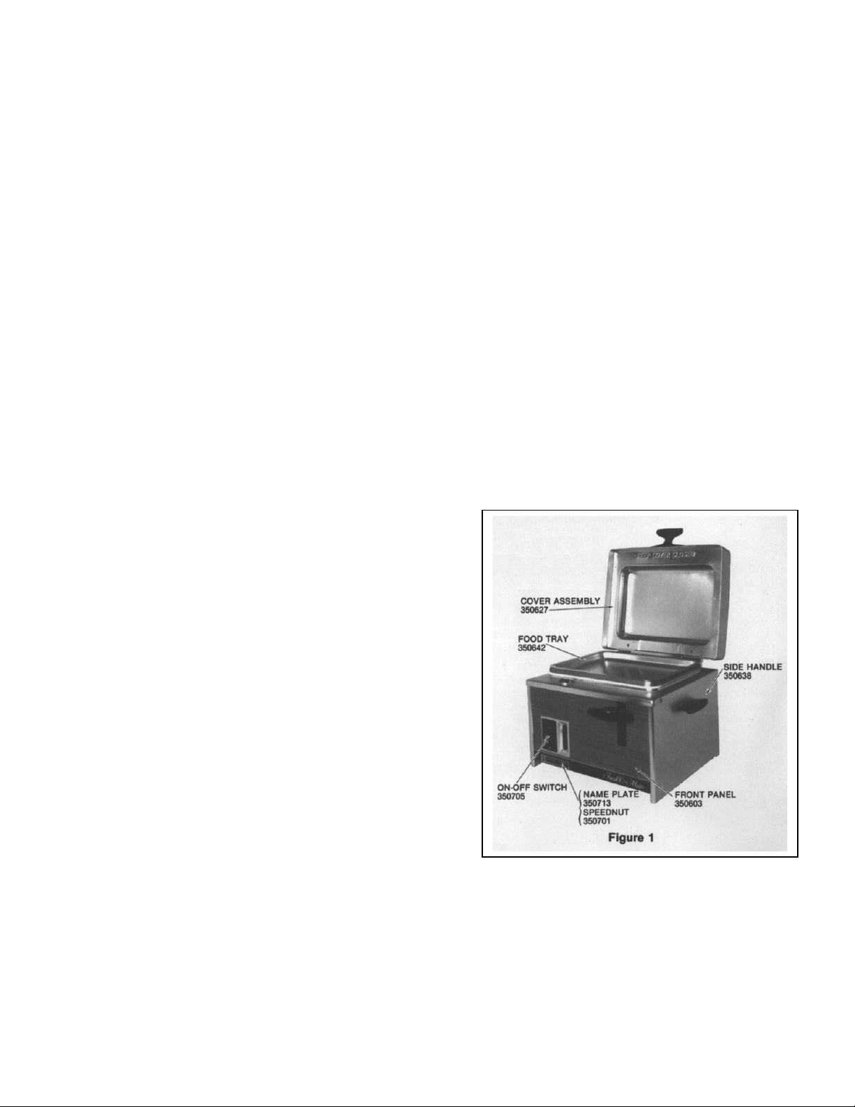
ON-OFF SWITCH #350705 FIGURES 1&2.
1. Switch on provides power to heater plate thru thermostat. If switch is on and no heat from heater
plate, check switch, thermostat, thermal cut off, and heater plate for continuity.
PILOT LIGHT #350605 FIGURES 1&2
1. Lights when switch is first turned on, then cycles with thermostat. If light does not light, check
continuity of pilot light, switch and thermostat.
THERMOSTAT #350620 FIGURE 2.
1. Thermostat should remain closed until a temperature of 360° F (182° C) is attained on the heater
plate. Temperature is measured on the top of food tray #350642, (Figure 1), at a point 2 5/8” from
front and right edges.
HEATER PLATE #350727 Figure 3.
1. Heater plate draws approximately 12.5 amps.
2. If heating is not evident, a continuity check should be made at heater terminals.
3. If heater plate is not defective approximately 9 ½ ohms should be measured. If approximately 9 ½
ohms is not measured or if heater plate is open or shorted, replace element.
THERMAL CUTOFF WIRE HARNESS #350703 (FIGURE 2).
approximately 468° F (242°
lead determination refer to schematic (Page 12).
POWER CORD #350725 FIGURE 2.
1. This cord is equipped with a 120 VAC grounded plug.
2. The lead determination for connection within unit are shown on the schematic (Page 12)
WIRE HARNESS #350704 FIGURE # 2.
1. This harness connects switch & thermostat.
TO REMOVE FRONT PANEL # 350603 FIGURE 2
1. Remove cover assembly #350627 by removing hinge pin #350545 (Figure 3),or by compressing
spring loaded pins in hinges(new style).
2. Lay on back and remove 2 screws #350531 on bottom front (figure 4) and slide out panel.
TO REMOVE HEATER PLATE ASSEMBLY #350729 (FIGURES 3&7)
1. Remove front panel as above.
2. Remove electrical leads from heater plate (Figure 2).
3. Loosen nuts from water tube and remove (Figure 9),remove screw from filler tube stop and loosen
filler tube nut.
4. Loosen hinge screws #350543 (Removal not necessary). (Unit upright),not needed for new style
hinges.
5. Remove shelf screws #350636 (Figure 3).
6. Remove hex nuts (4) #350574 from support studs (bottom of unit figure 3). (Unit on back).
7. Lift heater plate assembly up enough to loosen thermostat bulb clamp #350621 and remove
thermostat bulb.
8. Heater plate assembly may now be lifted up and out. (unit upright).
Fresh-O-Matic 4000 Series Service Manual
4
Page 5

TO REMOVE SPRAY NOZZLE #350593 (FIGURE 3).
1. Remove front panel as indicated on page 4.
2. Remove spray nozzle locknut #350594 and then with pliers remove nozzle #350593.
TO CLEAN SPRAY NOZZLE #350593 (FIGURE 3).
The spray nozzle may be cleaned and serviced from the front of the unit by removing front panel.
Loosen water tube nut #350597, remove spray nozzle locknut #350594 and remove spray nozzle
#350593. It may be necessary to use pliers to remove spray nozzle. If difficulty is experienced removing
spray nozzle locknut, heat the plate around the nut with a torch.
Fresh-O-Matic 4000 Series Service Manual
5
Page 6

TO REPLACE HEATER PLATE ASSEMBLY #350729 (FIGURE 3).
1. If necessary replace rubber shelf seal #350538.
2. Place heater plate assembly into shelf #350635 with element terminals facing the filler tube hole.
3. Replace support studs #350570 into heater plate assembly (apply RTV to threads of stud) and
tighten.
4. Place heater plate assembly and shelf on top of unit and slide thermostat bulb under clamp and
tighten.
5. Insert heater plate assembly into top opening (element terminals facing front) and insert 4 support
studs into holes on bottom of unit. Align filler tube and tighten filler tube nut and replace filler tube
stop screw.
6. Tighten hinge screws and replace shelf screws.
7. Replace washers and nuts on support studs, replace wires to heater terminals and replace water
tube.
TO REMOVE WATER PUMP (FIGURE 5).
1. Remove front panel and water tube.
2. Remove four screws #350586 from water pump cap #350585.
3. Pump can now be pulled out of the bottom of the unit.
4. Install in reverse order, Be sure to engage the pump with the pump lever.
Fresh-O-Matic 4000 Series Service Manual
6
Page 7

TO REPLACE FILLER GLASS #350599
FIGURE 6.
1.Unscrew filler tube nut #350562 and remove
all glass.
2.Insert new glass being sure top and bottom
filler tube gaskets #350561 & 350560 are good
and sealing properly.
3. Replace filler tube nut.
Fresh-O-Matic 4000 Series Service Manual
7
Page 8

Turn locknut a partial turn, then apply
NOTICE: We do not, under in-warranty repair of the #4000 fresh-o-matic, honor the complete
replacement of a heater plate assembly. Normally many of these parts are salvageable.
HEATER PLATE ASSEMBLY INSTRUCTIONS FIGURES 7 & 8.
ALL SURFACES MUST BE CLEAN, DRY AND BONDED TOGETHER WITH RTV #350716 PER
FOLLOWING INSTRUCTIONS. ALWAYS REPLACE ALL STUDS.
1. Remove studs from food tray casting #350642 by knocking out from bottom and reinsert new
studs#350571. (Be sure top of stud is flush with the top surface of the food tray casting).
2. Place food tray casting #350642 on work table with studs up.
3. Insert 4 steel balls #350568 in proper holes.
4. Place baffle plate #350566, chamfered holes down, across studs of food tray casting. Apply a 1/16”
bead of RTV half-way between holes and edge of plate. Invert baffle plate (now chamfered holes up)
and place over studs on food tray casting.
5. Place heater plate #350727 (terminals down) across studs of food tray casting. Apply a 1/16” bead of
RTV on flat surface between holes and edge of plate. Be sure there is no RTV in, or close to, the 4
steam grooves. Invert heater plate (terminals up) and place over studs.
Insert spray nozzle #350593 and nozzle locknut #350594.
loctite sealant #350648 around threads and complete tightening. Be sure spray nozzle is clean.
6. Place heater cover plate (open nozzle pointing down) over studs and apply 1/16” bead of RTV
between holes and edge EXCEPT on the side where the spray nozzle is located. On this side a bead
should be applied on the inside between the holes and the inside edge of the flat. Insert screw
#350626 as shown (figure 8) and invert heater plate cover, placing over studs. The heater plate
terminals and spray nozzle are on the same side. Tap each corner firmly with a rubber mallet to set
plates and spread RTV.
7. Place one drop of RTV next to each bolt. Install washers #350572 and nuts #350573 and tighten nuts
As follows:
a) The 14 nuts #350573 must be tightened and torqued to 110” lbs. to 125” lbs. max. and torqued in the
following sequence.
b) Snug all 14 nuts.
c) Torque center nut on longest side and its opposite.
d) Torque one of center nuts on end and its opposite.
e) Torque both remaining center nuts on side and their opposites.
f) Torque other center nuts on end and its opposite.
g) Torque all 4-corner nuts.
h) Repeat torque procedure once more.
Fresh-O-Matic 4000 Series Service Manual
8
Page 9

Fresh-O-Matic 4000 Series Service Manual
9
Page 10

SERVICE NOTES
In some cases on a repaired unit the water, when pumped into the unit, does not immediately turn into dry
super heated steam but comes out very moist.
First check if unit is at proper temperature. Depress pump handle injecting water into unit. If you hear a
steady frying sound (like water sizzling when dropped into a hot skillet) lasting as much as 15 seconds or
longer, boil out unit as follows.
1. Pump water into unit until water rises and covers the food tray approximately ¼” deep.
2. Place cloth over top of food tray for your protection or close lid until unit is done steaming.
3. Let unit operate until all water has steamed away.
This will assist in boiling away any film on heater plate allowing proper operation of unit. A heater plate
operating properly will produce a hiss as steam is forced thru the plates lasting about 5 seconds.
Fresh-O-Matic 4000 Series Service Manual
10
Page 11

2,8, 10
350730
Pump cap screw
350731
Part No Description Qty Fig Part No Description Qty Fig
350503 Strain Relief Bushing 1 2 350602 Foot pad 4 3,4
350514 Hex Nut SS 8-32 3 2,10 350603 Front Panel 1 1,3
350515 Lockwasher ss 8
350521 Fiberglass Sleeving 1 2 350620 Thermostat 1 2
350522 ScrewRHM ZN 6-32x3/8 1 2 350621 Thermostat bulb clamp 1 2,7,8
350523 Hex nut ST 6-32 1 2 350622 Screw RHMSS 6-32x3/16 4 2
350524 Lockwasher ZN #6 3 2 350626 Screw RHMSS 8-32x1/2 1 7,8
350531 Screw RHTSS #8x3/8 8 4 350627 Cover Assy. Complete 1 1,3,10
350538 Shelf Seal 1 3 350628 Cover Liner 1 10
350543 Screw PHMNI 8-32x7/8 4 3 350629 Liner Support 1 10
350545 Hinge Pin 1 3 350630 Cover Handle 1 4,10
350547 Screw PHMSS 8-32x3/8 4 350631 Case Assembly 1 2,3
350551 Water Tank Cover 1 2,6 350632 Support Assembly 1 2,3
350552 Screw RHTSS #4x3/8 2 6 350635 Shelf 1 3
350553 Water Tank Seal 1 6 350636 Shelf Screw #6x1/4 3 3
350554 Rubber Grommet 1 6 350637 Hinge End 2 3
350555 Washer, Flat ZN 5/16 2 3 350638 Side Handle 2 1
350557 Drain Plug 1 4,6 350639 Bakelite Grommet 1 2
350558 Plug Gasket 1 6 350640 Tank Assembly 1 3,6
350559 Filler Tube Glass 1 6 350641 Filler Tube Stop 1 4
350560 Fillerube Gasket, BTM. 350642 Food Tray W/14 Studs 1 1,7,8
350561 Filler Tube Gasket, Top 1 2,6 350644 Pump Lever w/Handle 1 3,4
350562 Filler Tube Nut 1 6 350645 Pump Lever Bracket 1 3
350563 Filler Tube & Cap 1 3 350646 Compression Nut BR 1 9
350566 Baffle Plate 1 7,8 350647 Compression Sleeve ¼” 1 9
350568 Stainless Steel Ball 4 7,8 350701 Speed Nut ¼” Stud 2 1
350570 Support Stud 4 3,7,8 350703 Wiring Harness wlThermal
350571 Food Tray Studs 14 3,7,8 350704 Wiring Harness 1 2
350572 Flat Washer AL5/16-18 16 3,7,8 350705 On-off switch 1 1,2
350573 Hex Nut AL 5/16-18 16 3,7,8 350710 Pump Assembly 1 5
350574 Hex Nut SS ¼-20 4 3,4 350713 Nameplate 1 1
350575 Lockwasher SS IN ¼ 4 3,4 350714 Ring Tongue Terminal 4 2
350576 Pump Body Assembly 1 5 350725 Power Cord 1 2
350577 PumpPlunger&Stem
Assy
350578 Pumpspacer&valve Assy
350579 Pump cap 1 5
350580 Pump spring 1 5 350732 NS Heater plate assy 240v
350581 Roll pin 1 5
350582 Pump tube cap 1 5 NOT SHOWN !
350583 Pump adapter plate 1 5 350734 Pin vise bit FOM 5
350584 Pump retainer ring 1 5 350735 Cover assy NS (BLACK) 1
350585 Pump bottom cap 1 5 350736 Hinge,Q.D. leaf FOM 2
350586
350587 “O” Ring 1 5 350738 Screw,captive,FOM 4
350588 “O” Ring 1 5 350739 Retainer,captive,FOM 4
350589 Pump screen 1 6
350591 Pump lever pin 1 3
350592 Cotter pin 1/16x1/2 1 3
350593 Spray nozzle assy. 1 3,7,8
350594 Spray nozzle locknut 1 3,7,8 350599 Compound #111
350595 Water tube assembly 1 3,7,8 Dow corning
350596 Brass elbow ¼” OD 1 6 350648 Loctite sealant
350597 Water tube nut BR ¼” 1 3 592-31/50cc
350598 Food tray liner 1 3 350716 RTV Sealant #106
1 5 350728 Heater plate cover 1 7,8
1 5 350729 Heater plate assy complete 1 7
4 5 350737 Receptacle,captive,FOM 4
350605 Pilot Light 125 volt red 1 2
1 2
Cut-Off
NS Heater plate 240v
Sealant RTV 3140 Clear
Fresh-O-Matic 4000 Series Service Manual
11
Page 12

WIRING SCHEMATIC MODEL 4000-4
Fresh-O-Matic 4000 Series Service Manual
12
 Loading...