

Page 1
Operator’s Manual
FLEXTEC ™ 450
For use with machines having Code Numbers:
11626, 11754, 11941, 12038
Register your machine:
www.lincolnelectric.com/register
Authorized Service and Distributor Locator:
www.lincolnelectric.com/locator
Save for future reference
Date Purchased
Code: (ex: 10859)
Serial: (ex: U1060512345)
IM10062-C | Issue D ate Oct-13
© Lincoln Global, Inc. All Rights Reserved.
Page 2
THANK YOU FOR SELECTING
AT ALL
TIMES.
SPECIA L SI TUATIONS
Additional precautionary measures
A QUALITY PRODUCT BY
LINCOLN ELEC TRIC.
PLEASE EXAMINE CARTON AND EQUIPMENT FOR
DAMAGE IMMEDIATELY
When this equipment is shipped, title passes to the purchaser upon
receipt by the carrier. Consequently, Claims for material damaged in
shipment must be made by the purchaser against the transportation
company at the time the shipment is received.
SAFETY DEPENDS ON YOU
Lincoln arc welding and cutting equipment is designed and built with
safety in mind. However, your overall safety can be increased by
proper installation ... and thoughtful operation on your part.
DO NOT INSTALL, OPERATE OR REPAIR THIS EQUIPMENT
WITHOUT READING THIS MANUAL AND THE SAFETY PRECAUTIONS
CONTAINED THROUGHOUT. And, most importantly, think before you
act and be careful.
WARNING
This statement appears where the information must be followed
exactly to avoid serious personal injury or loss of life.
CAUTION
This statement appears where the information must be followed to
avoid minor personal injury or damage to this equipment.
KEEP YOUR HEAD OUT OF THE FUMES.
DON’T get too close to the arc. Use
corrective lenses if necessary to
stay a reasonable distance away
from the arc.
READ and obey the Material Safety
Data Sheet (MSDS) and the warning
label that appears on all containers
of welding materials.
USE ENOUGH VENTILATION or
exhaust at the arc, or both, to keep
the fumes and gases from your breathing zone and the general area.
IN A LARGE ROOM OR OUTDOORS, natural ventilation may be
adequate if you keep your head out of the fumes (See below).
USE NATURAL DRAFTS or fans to keep the fumes away from your
face.
If you de velop unusual symptoms, see your supervisor. Perhaps the
welding atmosphere and ventilation system should be checked.
WEAR CORRECT EYE, EAR & BODY PROTECTION
PROTECT your eyes and face with welding helmet
properly fitted and with proper grade of filter plate
(See ANSI Z49.1).
PROTECT your body from welding spatter and arc
flash with protective clothing including woolen
clothing, flame-proof apron and gloves, leather
leggings, and high boots.
PROTECT others from splatter, flash, and glare with
protective screens or barriers.
IN SOME AREAS, protection from noise may be
appropriate.
BE SURE protective equipment is in good condition.
Also, wear safety glasses in work area
DO NOT WELD OR CUT containers or materials which previously had
been in contact with hazardous substances unless they are properly
cleaned. This is extremely dangerous.
DO NOT WELD OR CUT painted or plated parts unless special
precautions with ventilation have been taken. They can release highly
toxic fumes or gases.
PROTECT compressed gas cylinders from excessive heat, mechanical
shocks, and arcs; fasten cylinders so they cannot fall.
BE SURE cylinders are never grounded or part of an electrical circuit.
REMOVE all potential fire hazards from welding area.
ALWAYS HAVE FIRE FIGHTING EQUIPMENT READY FOR
IMMEDIATE USE AND KNOW HOW TO USE IT.
Page 3
SECTION A:
Diesel Engines
Gasoline Engines
WARNINGS
CALIFORNIA PROPOSITION 65 WARNINGS
Diesel engine exhaust and some of its constituents are known
to the State of California to cause cancer, birth defects, and other
reproductive harm.
The engine exhaust from this product contains chemicals known
to the State of California to cause cancer, birth defects, or other
reproductive harm.
ARC WELDING CAN BE HAZARDOUS. PROTECT
YOURSELF AND OTHERS FROM POSSIBLE SERIOUS
INJURY OR DEATH. KEEP CHILDREN AWAY. PACEMAKER WEARERS SHOULD CONSULT WITH THEIR
DOCTOR BEFORE OPERATING.
Read and understand the following safety highlights. For additional
safety information, it is strongly recommended that you purchase a
copy of “Safety in Welding & Cutting - ANSI Standard Z49.1” from the
American Welding Society, P.O. Box 351040, Miami, Florida 33135 or
CSA Standard W117.2-1974. A Free copy of “Arc Welding Safety”
booklet E205 is available from the Lincoln Electric Company, 22801
St. Clair Avenue, Cleveland, Ohio 44117-1199.
BE SURE THAT ALL INSTALLATION, OPERATION,
MAINTENANCE AND REPAIR PROCEDURES ARE
PERFORMED ONLY BY QUALIFIED INDIVIDUALS.
SAFETY
1.d. Keep all equipment safety guards, covers and
devices in position and in good repair.Keep
hands, hair, clothing and tools away from
V-belts, gears, fans and all other moving parts
when starting, operating or repairing
equipment.
1.e. In some cases it may be necessary to remove safety guards to
perform required maintenance. Remove guards only when
necessary and replace them when the maintenance requiring
their removal is complete. Always use the greatest care when
working near moving parts.
1.f. Do not put your hands near the engine fan. Do not attempt to
override the governor or idler by pushing on the throttle control
rods while the engine is running.
1.g. To prevent accidentally starting gasoline engines while turning
the engine or welding generator during maintenance work,
disconnect the spark plug wires, distributor cap or magneto wire
as appropriate.
1.h. To avoid scalding, do not remove the radiator
pressure cap when the engine is
hot.
ELECTRIC AND
MAGNETIC FIELDS MAY
BE DANGEROUS
2.a. Electric current flowing through any conductor
causes localized Electric and Magnetic Fields (EMF). Welding
current creates EMF fields around welding cables and welding
machines
FOR ENGINE POWERED
EQUIPMENT.
1.a. Turn the engine off before troubleshooting
and maintenance work unless the
maintenance work requires it to be running.
1.b. Operate engines in open, well-ventilated
areas or vent the engine exhaust fumes outdoors.
1.c. Do not add the fuel near an open flame
welding arc or when the engine is running.
Stop the engine and allow it to cool before
refueling to prevent spilled fuel from
vaporizing on contact with hot engine parts
and igniting. Do not spill fuel when filling
tank. If fuel is spilled, wipe it up and do not start engine until
fumes have been eliminated.
2.b. EMF fields may interfere with some pacemakers, and welders
having a pacemaker should consult their physician before
welding.
2.c. Exposure to EMF fields in welding may have other health effects
which are now not known.
2.d. All welders should use the following procedures in order to
minimize exposure to EMF fields from the welding circuit:
2.d.1. Route the electrode and work cables together - Secure
them with tape when possible.
2.d.2. Never coil the electrode lead around your body.
2.d.3. Do not place your body between the electrode and work
cables. If the electrode cable is on your right side, the
work cable should also be on your right side.
2.d.4. Connect the work cable to the workpiece as close as possible to the area being welded.
2.d.5. Do not work next to welding power source.
3
Page 4
SAFETY
ELECTRIC SHOCK
CAN KILL.
3.a. The electrode and work (or ground) circuits are
electrically “hot” when the welder is on. Do
not touch these “hot” parts with your bare skin
or wet clothing. Wear dry, hole-free gloves to insulate hands.
3.b. Insulate yourself from work and ground using dry insulation.
Make certain the insulation is large enough to cover your full area
of physical contact with work and ground.
In addition to the normal safety precautions, if
welding must be performed under electrically
hazardous conditions (in damp locations or while
wearing wet clothing; on metal structures such as
floors, gratings or scaffolds; when in cramped
positions such as sitting, kneeling or lying, if there
is a high risk of unavoidable or accidental contact
with the workpiece or ground) use the following
equipment:
• Semiautomatic DC Constant Voltage (Wire) Welder.
• DC Manual (Stick) Welder.
• AC Welder with Reduced Voltage Control.
3.c. In semiautomatic or automatic wire welding, the electrode,
electrode reel, welding head, nozzle or semiautomatic welding
gun are also electrically “hot”.
3.d. Always be sure the work cable makes a good electrical
connection with the metal being welded. The connection should
be as close as possible to the area being welded.
3.e. Ground the work or metal to be welded to a good electrical (earth)
ground.
3.f. Maintain the electrode holder, work clamp, welding cable and
welding machine in good, safe operating condition. Replace
damaged insulation.
3.g. Never dip the electrode in water for cooling.
3.h. Never simultaneously touch electrically “hot” parts of electrode
holders connected to two welders because voltage
two can be the total of the open circuit voltage of both
welders.
3.i. When working above floor level, use a safety belt to protect
yourself from a fall should you get a shock.
between the
ARC RAYS CAN BURN.
4.a. Use a shield with the proper filter and cover plates to protect your
eyes from sparks and the rays of the arc when welding or
observing open arc welding. Headshield and filter lens should
conform to ANSI Z87. I standards.
4.b. Use suitable clothing made from durable flame-resistant material
to protect your skin and that of your helpers from the arc rays.
4.c. Protect other nearby personnel with suitable, non-flammable
screening and/or warn them not to watch the arc nor expose
themselves to the arc rays or to hot spatter or metal.
FUMES AND GASES
CAN BE DANGEROUS.
5.a. Welding may produce fumes and gases
hazardous to health. Avoid breathing these
fumes and gases. When welding, keep your head out of the fume.
Use enough ventilation and/or exhaust at the arc to keep fumes
and gases away from the breathing zone. When welding
with electrodes which require special ventilation
such as stainless or hard facing (see instructions
on container or MSDS) or on lead or cadmium
plated steel and other metals or coatings which
produce highly toxic fumes, keep exposure as low
as possible and within applicable OSHA PEL and
ACGIH TLV limits using local exhaust or
mechanical ventilation. In confined spaces or in
some circumstances, outdoors, a respirator may
be required. Additional precautions are also
required when welding on galvanized steel.
5. b. The operation of welding fume control equipment is affected by
various factors including proper use and positioning of the
equipment, maintenance of the equipment and the specific
welding procedure and application involved. Worker exposure
level should be checked upon installation and periodically
thereafter to be certain it is within applicable OSHA PEL and
ACGIH TLV limits.
5.c. Do not weld in locations near chlorinated hydrocarbon vapors
coming from degreasing, cleaning or spraying operations. The
heat and rays of the arc can react with solvent vapors to form
phosgene, a highly toxic gas, and other irritating products.
3.j. Also see It ems 6.c. and 8.
5.d. Shielding gases used for arc welding can displace air and
injury or death. Always use enough ventilation, especially in
confined areas, to insure breathing air is safe.
5.e. Read and understand the manufacturer’s instructions for this
equipment and the consumables to be used, including the
material safety data sheet (MSDS) and follow your employer’s
safety practices. MSDS forms are available from your welding
distributor or from the manufacturer.
5.f. Also see item 1.b.
4
cause
Page 5
SAFETY
WELDING AND CUTTING
SPARKS CAN CAUSE
FIRE OR EXPLOSION.
6.a. Remove fire hazards from the welding area. If
this is not possible, cover them to prevent the
welding sparks from starting a fire. Remember that welding
sparks and hot materials from welding can easily go through
small cracks and openings to adjacent areas. Avoid welding near
hydraulic lines. Have a fire extinguisher readily available.
6.b. Where compressed gases are to be used at the job site, special
precautions should be used to prevent hazardous situations.
Refer to “Safety in Welding and Cutting” (ANSI Standard Z49.1)
and the operating information for the equipment being used.
6.c. When not welding, make certain no part of the electrode circuit is
touching the work or ground. Accidental contact can cause
overheating and create a fire hazard.
6.d. Do not heat, cut or weld tanks, drums or containers until the
proper steps have been taken to insure that such procedures will
not cause flammable or toxic vapors from substances inside.
They can cause an explosion even though they have been
“cleaned”. For information, purchase “Recommended Safe
Practices for the Preparation for Welding and Cutting of
Containers and Piping That Have Held Hazardous Substances”,
AWS F4.1 from the American Welding Society (see address
above).
6.e. Vent hollow castings or containers before heating, cutting or
welding. They may explode.
6.f. Sparks and spatter are thrown from the welding arc. Wear oil free
protective garments such as leather gloves, heavy shirt, cuffless
trousers, high shoes and a cap over your hair. Wear ear plugs
when welding out of position or in confined places. Always wear
safety glasses with side shields when in a welding area.
6.g. Connect the work cable to the work as close to the welding area
as practical. Work cables connected to the building framework or
other locations away from the welding area increase the
possibility of the welding current passing through lifting chains,
crane cables or other alternate circuits. This can create fire
hazards or overheat lifting chains or cables until they fail.
6.h. Also see item 1.c.
CYLINDER MAY EXPLODE IF
DAMAGED.
7.a. Use only compressed gas cylinders containing
the correct shielding gas for the process used
and properly operating regulators designed for
the gas and pressure used. All hoses, fittings,
etc. should be suitable for the application and
maintained in good condition.
7.b. Always keep cylinders in an upright position securely chained to
an undercarriage or fixed support.
7.c. Cylinders should be located:
• Away from areas where they may be struck or subjected
to physical damage.
• A safe distance from arc welding or cutting operations
and any other source of heat, sparks, or flame.
7.d. Never allow the electrode, electrode holder or any other
electrically “hot” parts to touch a cylinder.
7.e. Keep your head and face away from the cylinder valve outlet
when opening the cylinder valve.
7.f. Valve protection caps should always be in place and hand tight
except when the cylinder is in use or connected for use.
7.g. Read and follow the instructions on compressed gas cylinders,
associated equipment, and CGA publication P-l, “Precautions for
Safe Handling of Compressed Gases in
Cylinders,” available
from the Compressed Gas Association 1235 Jefferson Davis
Highway, Arlington, VA 22202.
FOR ELECTRICALLY
POWERED EQUIPMENT.
8.a. Turn off input power using the disconnect
switch at the fuse box before working on the
equipment.
8.b. Install equipment in accordance with the U.S. National Electrical
Code, all local codes and the manufacturer’s recommendations.
6.I. Read and follow NFPA 51B “ Standard for Fire Prevention During
Welding, Cutting and Other Hot Work”, available from NFPA, 1
Batterymarch Park, PO box 9101, Quincy, Ma 022690-9101.
6.j. Do not use a welding power source for pipe thawing.
8.c. Ground the equipment in accordance with the U.S. National
Electrical Code and the manufacturer’s recommendations.
Refer to
http://www.lincolnelectric.com/safety
for additional safety information.
Welding Safety
Interactive Web Guide
for mobile devices
5
Page 6

vi vi
TABLE OF CONTENTS
Page
Installation .......................................................................................................Section A
Technical Specifications ........................................................................................A-1
Welding Process, Physical Dimensions ..........................................................A-2
Safety Precautions ..........................................................................................A-3
VRD™ (Voltage Reduction Device) ..............................................................................A-3
Select Suitable Location..................................................................................A-3
Lifting...............................................................................................................A-3
Stacking ..........................................................................................................A-3
Environmental Limitations ...............................................................................A-3
Input and Grounding Connections ..................................................................A-3
High Frequency Protection ....................................................................................A-3
Input Connection ............................................................................................A-4
Input Connection .............................................................................................A-5
Input Fuse and Supply Wire Considerations...................................................A-5
Input Voltage Selection ...................................................................................A-5
Cable Connections..........................................................................................A-6
Recommended Electrode and Work Cable for arc Welding ..................................A-7
Output Cable Guidelines........................................................................................A-7
Connection Diagrams Flextec 450 to Wire Feeders ..............................A-8 thru A-11
________________________________________________________________________
Operation .........................................................................................................Section B
Safety Precautions ................................................................................................B-1
Graphic Symbols............................................................................................B-1, B-2
Product Description ..............................................................................................B-2
Duty Cycle .............................................................................................................B-2
Design Features ....................................................................................................B-2
Recommended Processes and Equipment ...........................................................B-3
Case Front Controls...............................................................................................B-4
Power-Up Sequence..............................................................................................B-5
Case Back Controls...............................................................................................B-5
Common Welding Procedures, Weld Controls and Displays..................B-5, thru B-8
_______________________________________________________________________
Accessories .....................................................................................................Section C
Options / Accessories............................................................................................C-1
________________________________________________________________________
Maintenance ....................................................................................................Section D
Safety Precautions ................................................................................................D-1
ISUAL INSPECTION...................................................................................................D-1
V
OUTINE MAINTENANCE ............................................................................................D-1
R
ERIODIC MAINTENANCE ...........................................................................................D-1
P
________________________________________________________________________
Section E ..............................................................................................Troubleshooting
Safety Precautions.................................................................................................E-1
How to Use Troubleshooting Guide.......................................................................E-1
Troubleshooting Guide ..........................................................................................E-2
Error Codes ............................................................................................E-3 Thru E-5
________________________________________________________________________
Wiring Diagram and Dimension Print ............................................................Section F
________________________________________________________________________
Parts List.........................................................................................P-652, P-732 Series
________________________________________________________________________
Page 7
A-1
INSTALLATION
A-1
TECHNICAL SPECIFICATIONS -
POWER SOURCE-INPUT VOLTAGE AND CURRENT
Model
K2882-2
Process
GMAW (CV)
GTAW (CC)
SMAW (CC)
FCAW-GS (CV)
Duty Cycle
60% rating
100% rating
Duty Cycle
60%
100%
60%
100%
60%
100%
60%
100%
Input Voltage ± 10%
380 / 460 / 575 / 3 / 50 / 60
Volts at Rated Amperes
FLEXTEC™ 450
Input Amperes
RATED OUTPUT
36.5V
34V
28V
26V
38V
36V
36.5V
34V
37 / 27 / 22
29 / 21 / 17
Idle Power
72 Watts
Max.
(fan on)
Amperes
450
400
450
400
450
400
450
400
Power Factor @
Rated Output
95%
60%
36.5V
450
FCAW-SS (CV)
100%
RECOMMENDED INPUT WIRE AND FUSE SIZES
VOLTAGE
50/60Hz
Maximum
Input
Cord Size
AWG SIZES
Amperes
380/3/50
460/3/60
575/3/60
(1)
Cord and Fuse Sizes based upon the U.S. National Electric Code and maximum output for 40°C (104°) ambient.
(2)
Also called “inverse time” or “thermal/magnetic” circuit breakers; circuit breakers that have a delay in tripping action that decreases as the
magnitude of current increases.
(3)
Type SD cord or similar in 30°C ambient.
42 A
30 A
25 A
(3)
(mm)
8(10)
8(10)
10(6)
34V
Type 75°C Copper
Wire in Conduit
2
AWG (mm
)
8 (10)
10 (6)
12 (4)
(1)
COPPER GROUNDING
CONDUCTOR
AWG (mm
2
)
10 (6)
10 (6)
12 (4)
400
Fuse (Super Lag) or
Breaker Size
50
45
35
(2)
FLEXTEC™ 450
Page 8
A-2
PROCESS
INSTALLATION
WELDING PROCESS
OUTPUT RANGE (AMPERES)
A-2
OCV (Uo)
GMAW (CV)
GTAW (CC)
SMAW (CC)
FCAW-GS (CV)
FCAW-SS (CV)
40-500
10-500
15-500
40-500
40-500
PHYSICAL DIMENSIONS
MODEL
K2882-2
HEIGHT
18.80in (478mm)
14.14in (359mm)
TEMPERATURE RANGES
OPERATING TEMPERATURE RANGE
Environmentally Hardened: 14°F to 131°F (-10°C to 55°C**)
IP23 155º(F) Insulation Class
* Weight does not include input cord.
** Output De-rated at Temperatures above 40°C.
60
24
60
60
60
WIDTH
STORAGE TEMPERATURE RANGE
Environmentally Hardened: -40°F to 185°F (-40°C to 85°C)
DEPTH
26.66in (677mm)
WEIGHT
125lbs (56.6kg)*
FLEXTEC™ 450
Page 9
A-3
SAFETY PRECAUTIONS
WARNING
ELECTRIC SHOCK can kill.
INSTALLATION
STACKING
The Flextec™ 450 cannot be stacked.
A-3
ONLY QUALIFIED PERSONNEL SHOULD
PERFORM THIS INSTALLATION.
• TURN OFF INPUT POWER TO THE
POWER SOURCE AT THE DISCONNECT
SWITCH OR FUSE BOX BEFORE WORKING ON THIS
EQUIPMENT. TURN OFF THE INPUT POWER TO
ANY OTHER EQUIPMENT CONNECTED TO THE
WELDING SYSTEM AT THE DISCONNECT SWITCH
OR FUSE BOX BEFORE WORKING ON THE EQUIPMENT.
• DO NOT TOUCH ELECTRICALLY HOT PARTS.
• ALWAYS CONNECT THE FLEXTEC™ 450 GROUNDING LUG (LOCATED INSIDE THE RECONNECT
INPUT ACCESS DOOR) TO A PROPER SAFETY
(EARTH) GROUND.
----------------------------------------------------------------------
ENVIRONMENTAL LIMITATIONS
The Flextec™ 450 is IP23 rated for use in an outdoor
environment. The Flextec™ 450 should not be subjected to falling water during use nor should any parts
of it be submerged in water. Doing so may cause
improper operation as well as pose a safety hazard.
The best practice is to keep the machine in a dry,
sheltered area.
Do not mount the Flextec™ 450 over combustible
surfaces. Where there is a combustible surface
directly under stationary or fixed electrical equipment, that surface shall be covered with a steel
plate at least .060” (1.6mm) thick, which shall
extend not less than 5.90” (150mm) beyond the
VRD™ (VOLTAGE REDUCTION DEVICE)
equipment on all sides.
-----------------------------------------------------------------------
(For Code 11941 only)
The VRD™ feature provides additional safety in the CC-
INPUT AND GROUNDING CONNECTIONS
Stick mode. The VRD™ reduces the OCV (Open Circuit
Voltage) at the welding output terminals while not welding to
less than 35VDC peak.
The VRD™ requires that the welding cable connections be
kept in good electrical condition because poor connections
will contribute to poor starting. Having good electrical connections also limits the possibility of other safety issues
such as heat-generated damage, burns and fires.
MACHINE GROUNDING
The frame of the welder must be grounded.
A ground terminal marked with the symbol
shown is located inside the reconnect/input
connection area for this purpose. See your local and
national electrical codes for proper grounding methods.
CAUTION
The machine is shipped with VRD™ “Disabled”. The VRD™
function can be disabled or enabled via dip switches on the
control P.C. board. Dip switch setting will differ depending
on input voltage.
The control board and dip switches can be accessed by
removing the case top and side as shown in the Operation
Section figure B.3.
HIGH FREQUENCY PROTECTION
Locate the Flextec™ 450 away from radio controlled
machinery. The normal operation of the Flextec™ 450
may adversely affect the operation of RF controlled
equipment, which may result in bodily injury or damage to the equipment.
SELECT SUITABLE LOCATION
LOCATION AND VENTILATION FOR COOLING
Place the welder where clean cooling air can freely
circulate in through the rear louvers and out through
the case sides. Dirt, dust, or any foreign material that
can be drawn into the welder should be kept at a minimum. Failure to observe these precautions can result
in excessive operating temperatures and nuisance
shutdowns.
HIGH TEMPERATURE OPERATION
LIFTING
Both handles should be used when lifting the
Flextec™ 450. When using a crane or overhead
device a lifting strap should be connected to both handles. Do not attempt to lift the Flextec™ 450 with
accessories attached to it.
WELDER OUTPUT RATINGS AT 55°C
ELEVATED TEMPERATURES
AMPS
340
375
400
450
DUTY CYCLE
100%
60%
40%
20%
VOLTS
34VDC
35VDC
36VDC
38VDC
TEMPERATURES
55°C
FLEXTEC™ 450
Page 10
A-4
INSTALLATION
A-4
WARNING
ELECTRIC SHOCK can kill.
ONLY A QUALIFIED ELECTRICIAN
SHOULD CONNECT THE INPUT
LEADS TO THE FLEXTEC™ 450.
CONNECTIONS SHOULD BE MADE IN ACCORDANCE WITH ALL LOCAL AND NATIONAL
ELECTRICAL CODES AND THE CONNECTION
DIAGRAM LOCATED ON THE INSIDE OF THE
RECONNECT/INPUT ACCESS DOOR OF THE
MACHINE. FAILURE TO DO SO MAY RESULT
IN BODILY INJURY OR DEATH.
----------------------------------------------------------------------
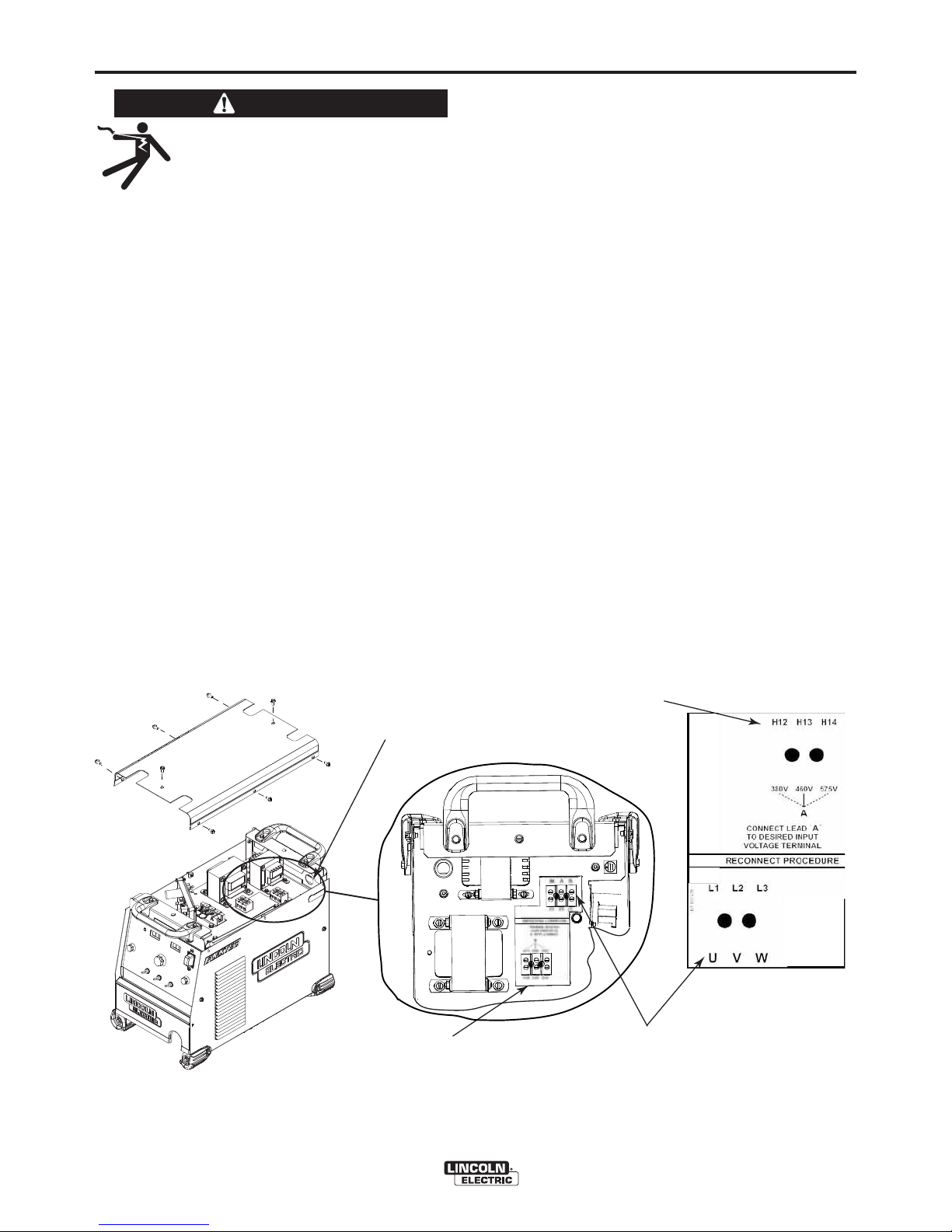
INPUT CONNECTION
(See Figure A.1)
For codes 11941 and below
Use a three-phase supply line. A 1.40 inch (36 mm)
diameter access hole for the input supply is located on
the case back. Connect L1, L2, L3 and ground
according to the Input Supply Connection Diagram
decal located on the internal horizontal panel.
INPUT VOLTAGE SELECTION
For codes 11941 and below
Welders are shipped connected for 460 Volt input
voltage. To move this connection to a different input
voltage, see the diagram located on the inside panel
in the reconnect/input connection area, illustrated in
Figure A.1. If the Auxiliary lead (indicated as ʻAʼ) is
placed in the wrong position and power is applied to
the machine, the machine will protect itself and display an error message:
• "Err" "713" or “714” will be shown on the display.
• The control board and switch boards will blink out
error "713" or “714” on their status leds.
• The weld output will be turned off and the control
board will force itself into an idle state.
• The machine will need to have the misconnect condition removed before it will recover.
To access the reconnect/input supply connection
blocks, remove the 8 screws that secure the case top
of the welder and remove the case top.
FIGURE A.1
POWER SUPPLY ACCESS HOLE
• Route input power cable through this hole.
RECONNECT TERMINAL BLOCK
• Reconnects auxiliary transformers
for the proper input voltages
RECONNECT TERMINAL BLOCK
POWER SUPPLY TERMINAL BLOCK
• Line Cord/Cable attaches here.
• A ground terminal marked with the symbol shown
is provided separate from this block for connecting the ground
lead of the line cord. (See your local and national electrical
codes for proper grounding methods.)
FLEXTEC™ 450
Page 11
A-5
INSTALLATION
A-5
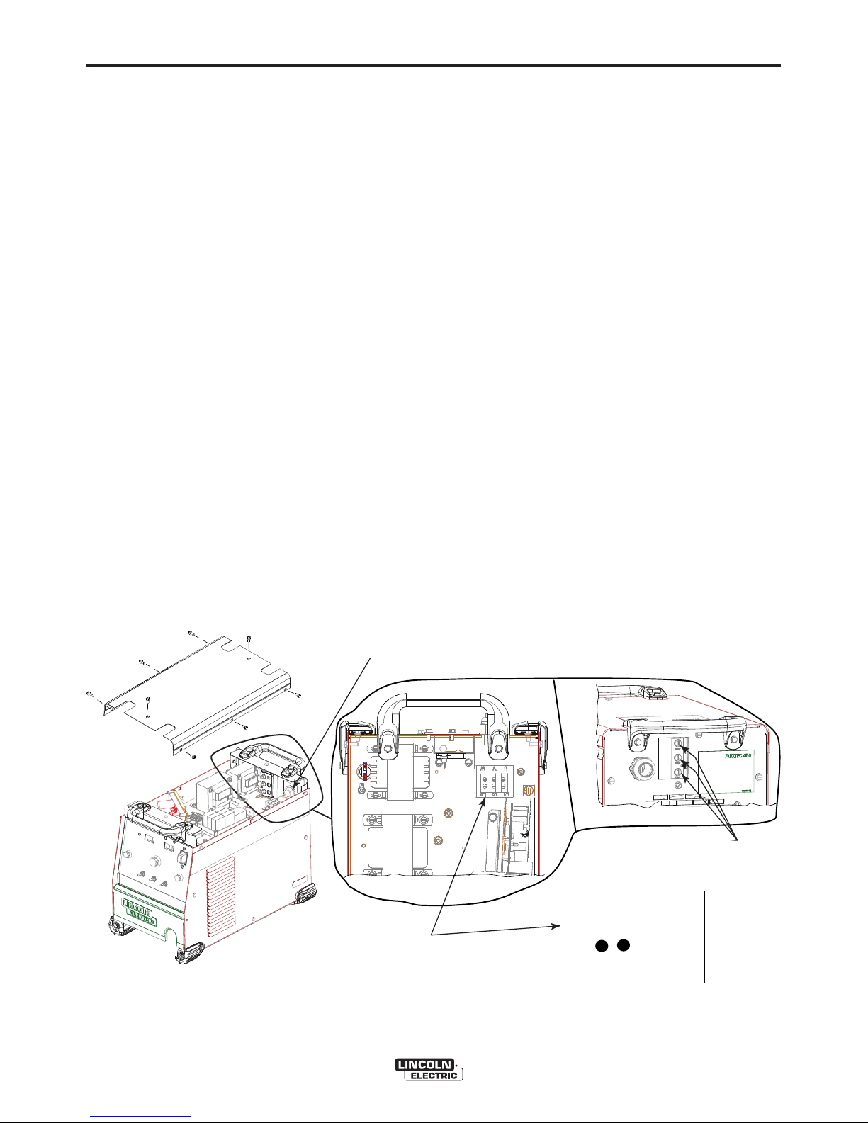
INPUT CONNECTION
(See Figure A.1a)
For codes 12038 and above
Use a three-phase supply line. A 1.40 inch (36 mm)
diameter access hole for the input supply is located on
the case back. Connect L1, L2, L3 and ground
according to the Input Supply Connection Diagram
decal located on the internal horizontal panel.
To access the input supply connection blocks, remove
the 8 screws that secure the case top of the welder
and remove the case top.
INPUT FUSE AND SUPPLY WIRE
CONSIDERATIONS
Refer to Specification in this Installation Section for
recommended fuse, wire sizes and type of the copper
wires. Fuse the input circuit with the recommended
super lag fuse or delay type breakers (also called
"inverse time" or "thermal/magnetic" circuit breakers).
Choose input and grounding wire size according to
local or national electrical codes. Using input wire
sizes, fuses or circuit breakers smaller than recommended may result in "nuisance" shut-offs from
welder inrush currents, even if the machine is not
being used at high currents.
INPUT VOLTAGE SELECTION
For codes 12038 and above
Welders are shipped connected for 460 Volt input
voltage. To move this connection to a different input
voltage, reconnect the auxiliary lead (indicated as ʼAʼ)
located at the back of the machine to the appropriate
receptacle as shown in Figure A.1a. If the Auxiliary
lead (indicated as ʻAʼ) is placed in the wrong position
and power is applied to the machine, the machine will
protect itself and display an error message:
• "Err" "713" or “714” will be shown on the display.
• The control board and switch boards will blink out
error "713" or “714” on their status leds.
• The weld output will be turned off and the control
board will force itself into an idle state.
• The machine will need to have the misconnect condition removed before it will recover.
FIGURE A.1a
POWER SUPPLY ACCESS HOLE
• Route input power cable through this hole.
POWER SUPPLY TERMINAL BLOCK
• Line Cord/Cable attaches here.
• A ground terminal marked with the symbol shown
is provided separate from this block for connecting the ground
lead of the line cord. (See your local and national electrical
codes for proper grounding methods.)
BACK OF MACHINE
RECONNECT TERMINAL BLOCK
• Reconnect auxiliary transformer
for the proper input voltage.
L1 L2 L3
U V W
FLEXTEC™ 450
Page 12
A-6
INSTALLATION
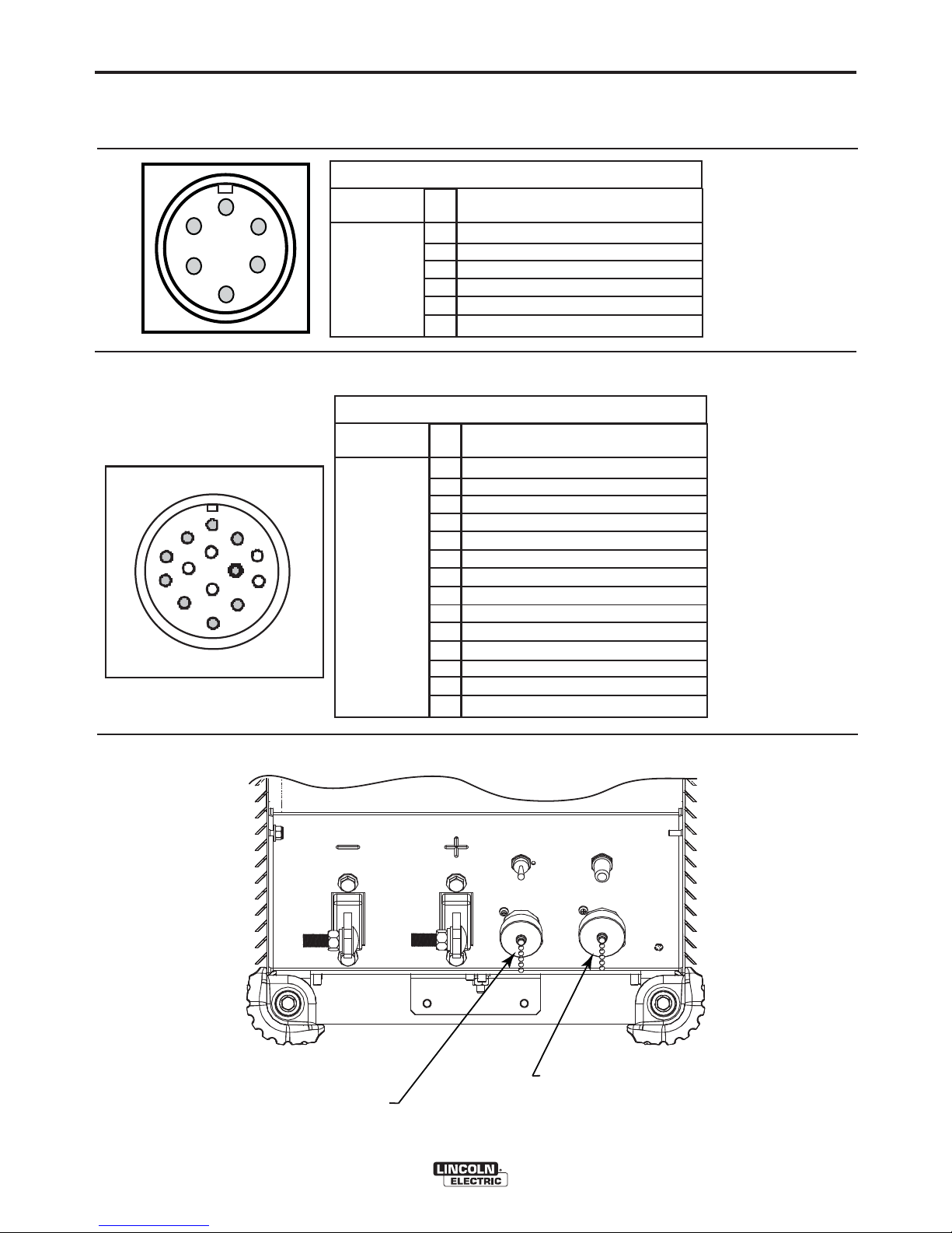
CABLE CONNECTIONS
See FIGURE A.2 for locating 6-pin and 14-pin connectors on the front of the FLEXTEC™ 450.
6-PIN REMOTE CONTROL CONNECTOR
A-6
F
E
A
D
C
G
F
M
E
L
D
B
H
I
N
J
K
A
B
C
Function
6-pin remote
control connector for
remote or
hand/foot
amptrol.
14-PIN CONNECTOR FOR WIRE FEEDER
Function
14 pin connector for
wire feeder
connectivity.
Pin
77 Remote potentiometer, 5K
A
76 Remote potentiometer, wiper
B
75 Remote potentiometer, common
C
Trigger, common
D
Trigger, input
E
Ground
F
Pin
A
Ground
B
Trigger, Common
C
Trigger input
D
77 Remote potentiometer, 5K
E
76 Remote potentiometer, wiper
F
75 Remote potentiometer, common
G
Voltage Sense (21)
H
Motor (42 VAC)
I
J
Motor (42 VAC)
K
L
M
N
Wiring
Wiring
FIGURE A.2
6-PIN REMOTE
CONTROL CONNECTOR
FLEXTEC™ 450
14-PIN CONNECTOR
FOR WIRE FEEDER
Page 13

A-7
INSTALLATION
A-7
RECOMMENDED ELECTRODE AND
WORK CABLE SIZES FOR ARC WELDING
General Guidelines
Connect the electrode and work cables between the
appropriate output studs of the Flextec™ 450 per the
following guidelines:
• Most welding applications run with the electrode
being positive (+). For those applications, connect
the electrode cable between the wire drive feed
plate and the positive (+) output stud on the power
source. Connect a work lead from the negative (-)
power source output stud to the work piece.
• When negative electrode polarity is required, such
as in some Innershield applications, reverse the output connections at the power source (electrode
cable to the negative (-) stud, and work cable to the
positive (+) stud).
The following recommendations apply to all output
polarities and weld modes:
• Select the appropriate size cables per the
“Output Cable Guidelines” (See Table A.1).
Excessive voltage drops caused by undersized
welding cables and poor connections often result in
unsatisfactory welding performance. Always use the
largest welding cables (electrode and work) that are
practical, and be sure all connections are clean and
tight.
• Route all cables directly to the work and wire
feeder, avoid excessive lengths and do not coil
excess cable. Route the electrode and work cables
in close proximity to one another to minimize the
loop area and therefore the inductance of the weld
circuit.
• Always weld in a direction away from the work
(ground) connection.
CONTROL CABLE CONNECTIONS
General Guidelines
Genuine Lincoln control cables should be used at all
times (except where noted otherwise). Lincoln cables
are specifically designed for the communication and
power needs of the Flextec™ 450. Most are designed
to be connected end to end for ease of extension.
Generally, it is recommended that the total length not
exceed 100 feet (30.5 m). The use of non-standard
cables, especially in lengths greater than 25 feet, can
lead to communication problems (system shutdowns),
poor motor acceleration (poor arc starting), and low
wire driving force (wire feeding problems). Always use
the shortest length of control cable possible, and DO
NOT coil excess cable.
Regarding cable placement, best results will be
obtained when control cables are routed separate
from the weld cables. This minimizes the possibility of
interference between the high currents flowing
through the weld cables, and the low level signals in
the control cables.
Note: Excessive heat in the weld circuit indicates
undersized cables and/or bad connections.
TABLE A.1
OUTPUT CABLE GUIDELINES
CABLE SIZES FOR COMBINED LENGTHS OF ELECTRODE AND WORK CABLES
AMPERES
200
200
250
250
250
250
300
300
350
400
400
500
** Tabled values are for operation at ambient temperatures of 104°F(40°C) and below. Applications above 104°F(40°C) may require cables
larger than recommended, or cables rated higher than 167°F(75°C).
PERCENT
DUTY
CYCLE
60
100
30
40
60
100
60
100
40
60
100
60
0 to 50Ft.
(0 to15m)
2
2
3
2
1
1
1
2/0
1/0
2/0
3/0
2/0
(RUBBER COVERED COPPER - RATED 167°F or 75°C)**
50 to 100Ft.
(15 to 30m)
2
2
3
2
1
1
1
2/0
1/0
2/0
3/0
2/0
100 to 150 Ft.
(30 to 46m)
2
2
2
1
1
1
1
2/0
2/0
2/0
3/0
3/0
150 to 200 Ft.
(46 to 61m)
1
1
1
1
1
1
1/0
2/0
2/0
3/0
3/0
3/0
200 to 250 Ft.
(61 to 76m)
1/0
1/0
1/0
1/0
1/0
1/0
2/0
3/0
3/0
4/0
4/0
4/0
FLEXTEC™ 450
Page 14
A-8
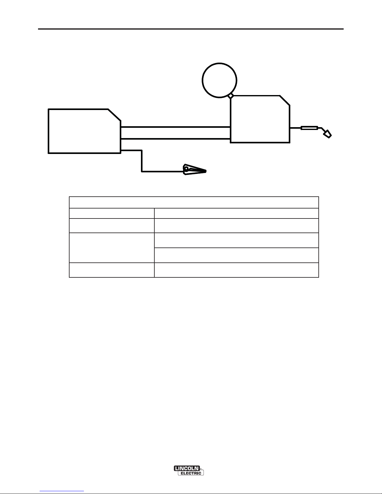
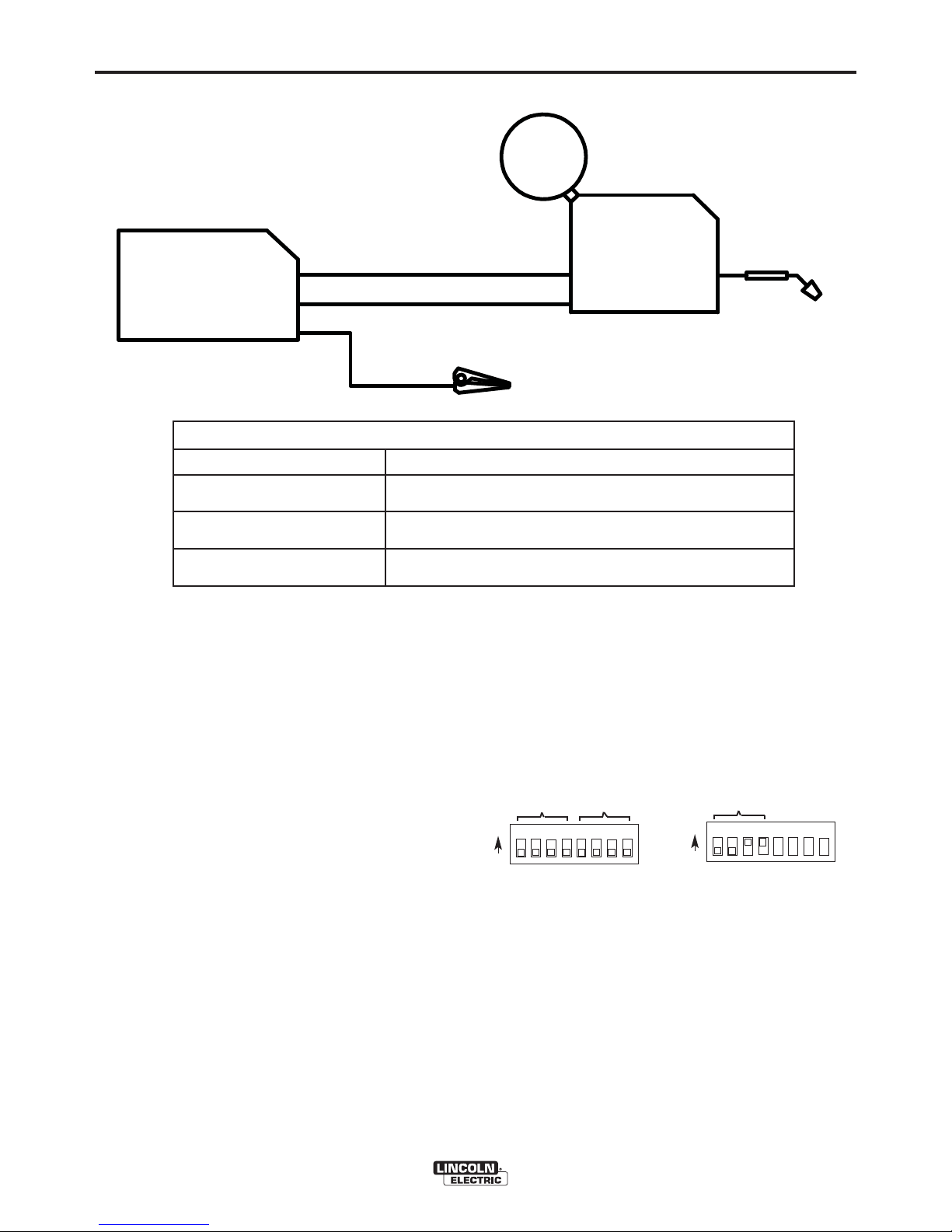
CONNECTING LF-72 AND LF-74 TO THE FLEXTEC™ 450
FLEXTEC™-450
WELD MODE
INSTALLATION
14-PIN CONTROL CABLE K1797-XX
ELECTRODE
WORK
CONTROL SETTING
CV, CV-INNERSHIELD
A-8
WIRE FEEDER
LF-72
LF-74
WELD TERMINALS
REMOTE/LOCAL
VOLTMETER POLARITY
OFF
LOCAL
(REMOTE IF K2329-1 INSTALLED)
PROCESS DEPENDENT
FLEXTEC™ 450
Page 15
A-9
INSTALLATION
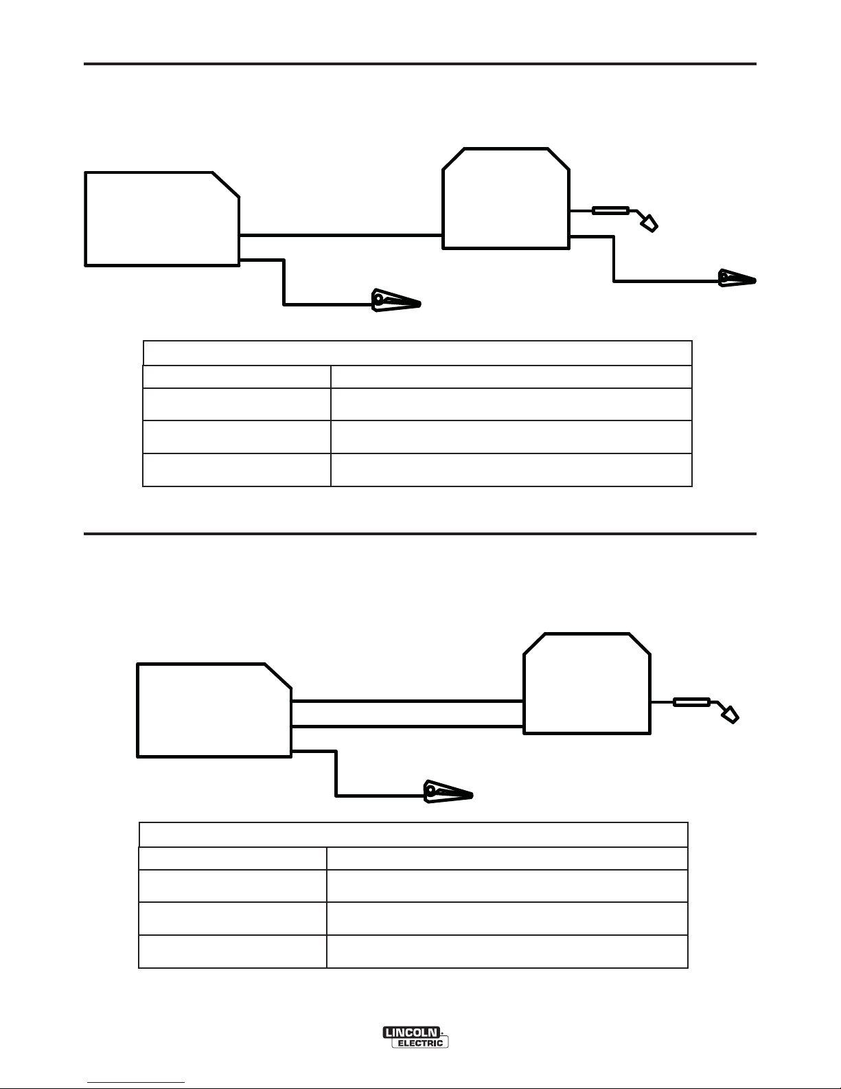
CONNECTING LN-10 AND DH-10 TO THE FLEXTEC™ 450
WIRE FEEDER
A-9
14-PIN CONTROL CABLE K1501-XX
FLEXTEC™-450
ELECTRODE
WORK
CONTROL SETTING
WELD MODE
WELD TERMINALS
REMOTE/LOCAL
VOLTMETER POLARITY
LN-10,DH-10 CONTROL SWITCH
SETUP
Initial set up of the LN-10, DH-10 control for the system components being used and for general operator
preferences is done using a pair of 8-pole DIP switches located inside the LN-10, DH-10 control box.
LN-10
DH-10
CV, CV-INNERSHIELD
OFF
REMOTE
PROCESS DEPENDENT
Setting the DIP Switches
The DIP switches are each labeled with an “ON”
arrow showing the on direction for each of the 8 individual switches in each DIP switch (S1 and S2). The
functions of these switches are also labeled and set
as described below:
Setup DIP Switch Access
1) Shut off the input power to the LN-10, DH-10 control by turning off the power at the welding power
source it is connected to.
2) Remove the two screws on the top of the LN-10,
DH-10 control box door and swing the door down
to open.
3) Locate the two 8-pole DIP switches, near the top
left corner of the LN-10, DH-10 Control P.C. board,
labeled S1 and S2.
4) Switch settings are only programmed during input
power-up restoration.
Pwr Sources
ON
12 3 4567 8
S1
FLEXTEC™ 450
Head
S1
Pwr Sources
ON
12 3 4567 8
S1
S1
Page 16
A-10
INSTALLATION
CONNECTING LN-15(K1870-1) TO THE FLEXTEC™ 450
WIRE FEEDER
A-10
FLEXTEC™-450
WELD MODE
WELD TERMINALS
REMOTE/LOCAL
VOLTMETER POLARITY
ELECTRODE
WORK
LN-15
(K1870-1)
CONTROL SETTING
CV, CV-INNERSHIELD
OFF
LOCAL
PROCESS DEPENDENT
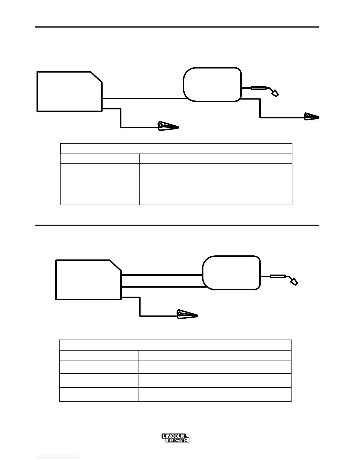
CONNECTING LN-15(K1871-1) TO THE FLEXTEC™ 450
WORK CLIP
FLEXTEC™-450
WELD MODE
WELD TERMINALS
REMOTE/LOCAL
VOLTMETER POLARITY
14-PIN CONTROL CABLE K1819-XX
ELECTRODE
WORK
CONTROL SETTING
CV, CV-INNERSHIELD
OFF
REMOTE
PROCESS DEPENDENT
FLEXTEC™ 450
WIRE FEEDER
LN-15
(K1871-1)
Page 17
A-11
INSTALLATION
CONNECTING LN-25 PRO AND LN-25 PIPE TO THE FLEXTEC™ 450
WIRE FEEDER
A-11
FLEXTEC™-450
WELD MODE
WELD TERMINALS
REMOTE/LOCAL
VOLTMETER POLARITY
CONNECTING LN-25 PRO DUAL POWER TO THE FLEXTEC™ 450
ELECTRODE
WORK
CONTROL SETTING
LN-25 PRO
LN-25 PIPE
WORK CLIP
CV, CV-INNERSHIELD
OFF
LOCAL
PROCESS DEPENDENT
WIRE FEEDER
FLEXTEC™-450
CONTROL CABLE K1797-XX
ELECTRODE
WORK
*
LN-25 PRO
DUAL POWER
CONTROL SETTING
WELD MODE
WELD TERMINALS
REMOTE/LOCAL
VOLTMETER POLARITY
*CONTROL CABLE SETUP SHOWN. REFER TO LN-25 PRO CONNECTION DIAGRAM IF SETTING UP
"ACROSS-THE-ARC" FEEDER.
FLEXTEC™ 450
CV, CV-INNERSHIELD
OFF
REMOTE
PROCESS DEPENDENT
Page 18
B-1
OPERATION
B-1
SAFETY PRECAUTIONS
Read this entire section of operating instructions
before operating the machine.
WARNING
ELECTRIC SHOCK can kill.
• Unless using cold feed feature, when
feeding with gun trigger, the
electrode and drive mechanism are
always electrically energized and
could remain energized several
seconds after the welding ceases.
• Do not touch electrically live parts or electrodes
with your skin or wet clothing.
• Insulate yourself from the work and ground.
• Always wear dry insulating gloves.
FUMES AND GASES can be
dangerous.
• Keep your head out of fumes.
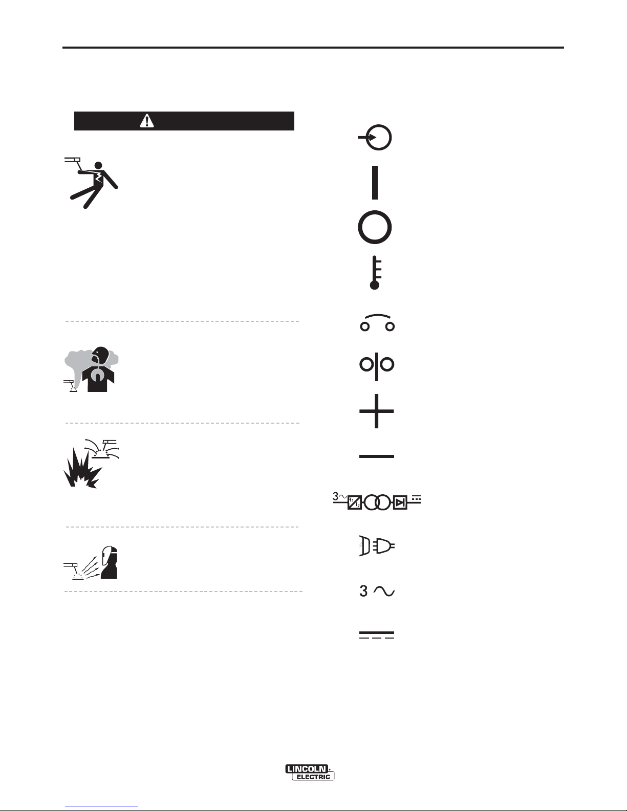
GRAPHIC SYMBOLS THAT
APPEAR ON THIS MACHINE
OR IN THIS MANUAL
INPUT POWER
ON
OFF
HIGH TEMPERATURE
CIRCUIT BREAKER
WIRE FEEDER
• Use ventilation or exhaust to remove
fumes from breathing zone.
WELDING SPARKS can cause
fire or explosion.
• Keep flammable material away.
• Do not weld on containers that have
held combustibles.
ARC RAYS can burn.
• Wear eye, ear, and body protection.
Observe additional guidelines detailed in the
beginning of this manual.
POSITIVE OUTPUT
NEGATIVE OUTPUT
3 PHASE INVERTER
INPUT POWER
THREE PHASE
DIRECT CURRENT
FLEXTEC™ 450
Page 19

B-2
OPERATION
B-2
GRAPHIC SYMBOLS THAT
APPEAR ON THIS MACHINE
OR IN THIS MANUAL
U
U
U
0
1
2
I
1
I
2
OPEN CIRCUIT
VOLTAGE
INPUT VOLTAGE
OUTPUT VOLTAGE
INPUT CURRENT
OUTPUT CURRENT
PROTECTIVE
GROUND
PRODUCT DESCRIPTION
The Flextec™ 450 is a multi-process CC/CV DC
inverter and is rated for 450 amps, 38 volts at a 60%
duty cycle. The Flextec is intended for both factory
and field operation. It comes in a compact, rugged
case that is designed for portability and outdoor use
with an IP23 environmental rating. The user interface
of the Flextec™ 450 is simple and intuitive. Weld
modes are selected by a 4 position selector switch.
Volts and Amps are displayed on an easy to view LED
display, and the amps and volts are set by a large output control knob. A hot start toggle selector switch
and an arc control knob allow for finer tuning of the
welding arc. The Flextec™ 450 operates on 380V,
460V, or 575V 50hz or 60hz power.
DUTY CYCLE
The Flextec™ 450 is capable of welding at a 100%
duty cycle (continuous welding) at 400 amps rated
output. The 60% rating is 450 amps base off of a 10
minute cycle - 6 minutes on time and 4 minutes off
time. The maximum output of the machine is 500
amps.
The Flextec™ 450 is also rated for Desert Duty, elevated temperature operation, in a 55°C(131°F) ambient. The machine is output de-rated for this application.
WARNING or CAUTION
Explosion
Dangerous Voltage
Shock Hazard
DESIGN FEATURES
• Severe Duty Design for outdoor use (IP23 rating).
• Passive Power Factor Correction – reliably gives
95% power factor for lower installation costs.
• 89% Efficiency rating – reduces electrical utility
costs.
• Simple user interface - designed with the operator in
mind. Getting setup for the weld is several clicks
away and even the most novice welder can be confident he is setup properly.
• F.A.N. (fan as needed). Cooling fan runs when the
output is energized and for a 5 minute cool down
period after output is disabled.
• Thermal protection by thermostats with Thermal
Indicator LED.
• Error Codes display on LED screen for ease of trouble shooting.
• Electronic over current protection.
• Input voltage misconnection protection.
• Utilizes digital signal processing and microprocessor
control.
FLEXTEC™ 450
Page 20

B-3
OPERATION
RECOMMENDED PROCESSES AND
EQUIPMENT
RECOMMENDED PROCESSES
The Flextec™ 450 is designed for CC-SMAW, CC-GTAW
(lift tig), CV-GMAW, CV-FCAW-SS and CV-FCAW-GS
welding processes. CAG (arc gouging) is also supported.
PROCESS LIMITATIONS
The Flextec™ 450 is suitable only for the processes listed.
EQUIPMENT LIMITATIONS
Operating Temperature Range is -10° C to + 55° C.
Output De-rated at Temperatures above 40°C.
COMMON EQUIPMENT PACKAGES
B-3
Basic Package
K2882-2
K2327-5
K2149-1
K1842-10
3100211
Common Optional Kits
K857
K857-1
K870
K963-3
Compatible Wire Feeders
All Models
Note: The
Flextec™ 450 is not compatible with 115V Wire Feeders.
Harris Regulator and gas hose
Remote Output Control (25 feet)
Remote Output Control (100 feet)
Flextec™ 450
LF-72 Bench Model
Work Lead Package
10 Ft. Weld Power Cable
Foot Amptrol
Hand Amptrol
LF-72
LF-74
LN-10
DH-10
LN-25 Pro
FLEXTEC™ 450
Page 21
B-4
OPERATION
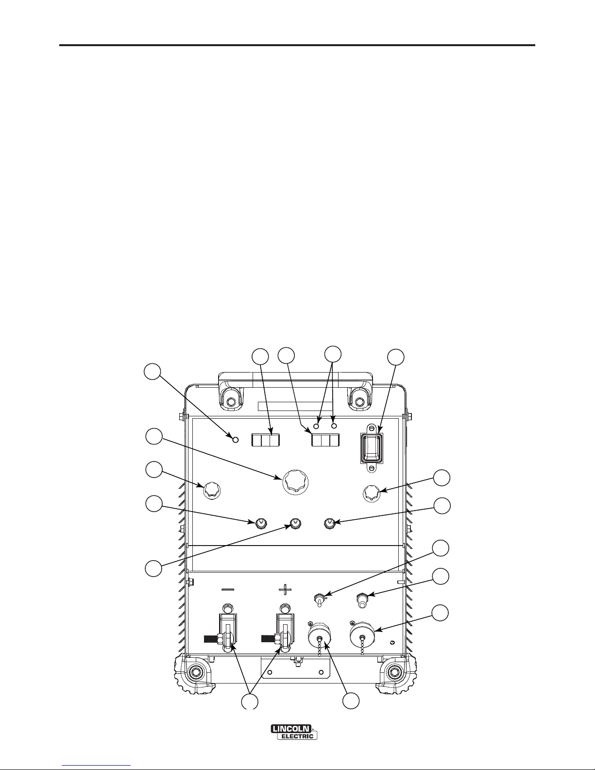
CASE FRONT CONTROL DESCRIPTIONS
(See Figure B.1)
1. Power Switch
2. Voltage Display Meter
B-4
11. Wire feeder voltmeter polarity selection toggle
switch
12. Circuit breaker reset button for the 14-pin wire
feeder connector
3. Amperage Display Meter
4. Thermal LED
5. Output Control Dial
6. Weld Process Selector Switch
7. Hot Start Toggle Switch
8. Output Control Local/Remote Toggle Switch
9. Arc Control Dial
10. Weld Terminals On/Remote toggle selector
switch
FIGURE B.1
3
4
13. 14-pin wire feeder circular connector
14. 6-pin remote circular connector
15. Positive and negative welding output studs
16. VRD™ (Voltage Reduction Device) Indicator
Lights (For Code 11941 only)
2
16
1
5
6
9
7
10
11
8
12
13
15
FLEXTEC™ 450
14
Page 22
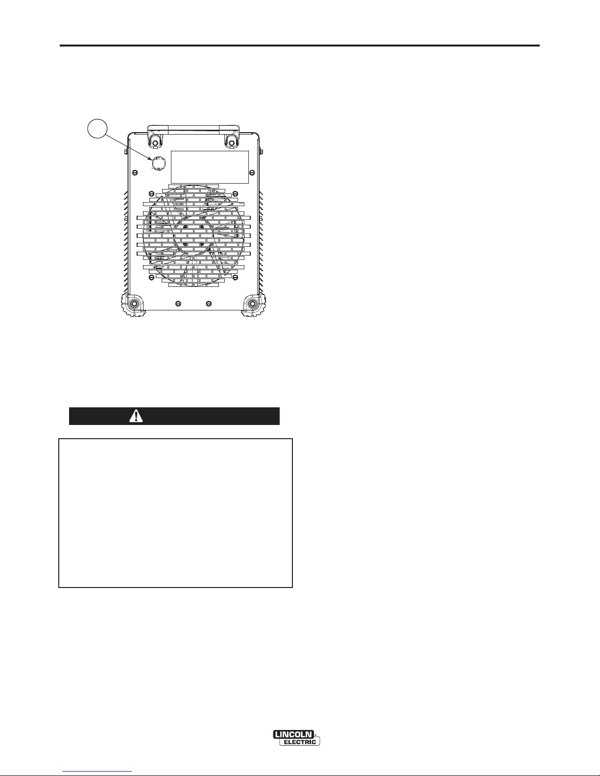
B-5
CASE BACK CONTROL
(See Figure B.2)
1. Input Power Cord Access Hole.
OPERATION
3. CV – This is CV (constant voltage) weld mode used
for welding the GMAW MIG welding process and
the FCAW-GS, flux cored gas shielded welding
process.
B-5
FIGURE B.2
1
POWER-UP SEQUENCE
When power is applied to the Flextec™ 450, the
displays will illuminate and display the voltage and/or
amperage settings.
COMMON WELDING PROCEDURES
WARNING
MAKING A WELD
The serviceability of a product or structure utilizing the welding programs is and must be the sole
responsibility of the builder/user. Many variables
beyond the control of The Lincoln Electric
Company affect the results obtained in applying
these programs. These variables include, but are
not limited to, welding procedure, plate chemistry
and temperature, weldment design, fabrication
methods and service requirements. The available
range of a welding program may not be suitable
for all applications, and the build/user is and must
be solely responsible for welding program selec-
tion.
The Flextec™ 450 is a multi-process inverter welder.
The Weld Process Selector Switch is used to set
the desired weld mode. The Flextec™ 450 has 4
selectable welding modes:
1. SMAW – This is a CC (constant current) weld
mode used for the SMAW stick welding process.
2. GTAW – This is a CC (constant current) weld
mode used for the GTAW TIG welding process.
4. CV-Innershield – This is a CV (constant voltage)
weld mode used for welding the FCAW-SS, flux
cored self shielded welding process
The Flextec™ 450 is also capable of gouging.
Gouging can be done in either the SMAW mode or the
CV and CV-Innershield modes.
In addition to the weld process selector switch, a hot
start toggle, output control dial and arc control dial are
provided to setup and fine tune the welding procedure.
WELD CONTROLS AND DISPLAYS
Weld Process Selector Switch
4 Position switch used to select the welding process.
Hot Start Toggle Switch
The Hot Start control regulates the starting current at
arc initiation. Hot Start can be set to “Off” and no
additional current is added at arc start. When set to
the “On” position, additional current (relative to the
preset current) is added at arc initiation.
Arc Control Dial
Full range selection of arc control from -10 to +10. In
CV mode, this control is an inductance control. In
stick mode, the control adjusts the arc force.
Output Control Dial
Output control is conducted by a single turn potentiometer. (Adjustment is indicated by the meters.)
When in Remote Mode, this control sets the maximum
welding current of the remote device. For example, full
depression of a foot or hand amptrol results in the preset level of current.
Voltage Display Meter
• Prior to CV operation (current flow), the meter displays desired preset voltage value.
• Prior to STICK or TIG operation, the meter displays
the Open Circuit Voltage of the Power Source or four
dashes if the output has not been turned on.
• During welding, this meter displays actual average
volts.
• After welding, the meter holds the actual voltage
value for 5 seconds. The displays blink indicating that
the machine is in the "hold" period.
• Output adjustment while in the "hold" period results in
the "prior to operation" characteristics.
FLEXTEC™ 450
Page 23

B-6
OPERATION
B-6
INTERNAL CONTROLS -
(For Code 11941 only)
Internal Controls Description
The Control PC Board has one bank of Dip Switches.
As shipped from the factory VRD™ mode is disabled
and the Dip Switches are all in the “off” position.
ENABLING VRD™
1 2 3 4 5 6 7 8
ON
OFF
To Enter VRD™ Mode (VRD™ Enabled)
a. For 380V input: Switch #5 in the “ON”
Position.
1 2 3 4 5 6 7 8
ON
OFF
b. For 460V input: Switch #6 in the “ON”
Position.
1 2 3 4 5 6 7 8
ON
OFF
c. For 575V input: Switch #5 and #6 in the
“ON” Position
CONTROL PCB LOCATION
1 2 3 4 5 6 7 8
ON
OFF
FIGURE B.3
CONTROL PCB
DIP SWITCH LOCATION
FLEXTEC™ 450
Page 24

B-7
Amperage Display Meter
• Prior to STICK or TIG operation (current flow), the
meter displays preset current value.
• Prior to CV operation, the meter displays four dashes indicating non-presettable AMPS.
• During welding, this meter displays actual average
amps.
• After welding, the meter holds the actual current
value for 5 seconds. The displays blink indicating
that the machine is in the "hold" period.
•Output adjustment while in the "hold" period results
in the "prior to operation" characteristics
Weld Terminals On/Remote Toggle Switch
• This switch determines the trigger location.
• When set to the “ON” position, the weld terminals
are at OCV (open circuit voltage) and ready to weld.
• When set to the “REMOTE” position, output is
enabled through a remote trigger.
Control - Local/Remote Toggle Switch
• Set the switch to “Local” to control output at the
machine by the Output Control dial.
• Set the switch to “REMOTE” to control output via a
remote device (K857 hand amptrol or K870 foot
amptrol) connected to the 6-pin remote connector
or a wire feeder connected to the 14-pin connector.
OPERATION
B-7
VRD™ (VOLTAGE REDUCTION DEVICE)
INDICATOR LIGHT
(For Code 11941 only)
There are 2 indicator lights on the case front of the
Flextec™ 450 above the Voltage LED Display to indicate the status of VRD™ operation. As shipped, the
VRD™ function is disabled. VRD™ is enabled by setting dip switches on the Control P.C. board (See
Internal Controls Figure B.3 in this Operation
Section). When VRD™ is active:
• A green light indicates the OCV (open circuit voltage) is less than 35V peak.
• A red light indicates the OCV is at or above 35V
peak.
• Both lights will illuminate for 5 seconds at power up.
For each weld mode, the VRD™ lights function as
shown in Table B.1:
Thermal Light
• This status light indicates when the power source
has been driven into thermal overload. If the output
terminals were "ON", the output will be turned back
on once the unit cools down to an acceptable temperature level. If the unit was operating in the
"REMOTE" mode, the trigger will need to be
opened before or after the thermal has cleared and
closed after the machine has cooled down to an
acceptable temperature to establish output.
TABLE B.1
VRD™ Indicator Lights
Mode
CC-SMAW
CC-GTAW
CV-GAS
CV-Innershield
CV-SAW
* It is normal for the lights to alternate between colors while welding.
OCV
While welding
OCV
While welding
Green (OCV reduced)
Green or Red (depends on weld voltage)*
Red (OCV Not Reduced)
Weld Terminals ʻONʼ
Red (OCV Not Reduced)
Weld Terminals Remotely Controlled
Gun Trigger Closed
Green (NO OCV)
Weld Terminals Remotely Controlled
Gun Trigger Open
Green or Red (depends on weld voltage)*
VRD™ “ON”
VRD™ “OFF”
No lights are
active
FLEXTEC™ 450
Page 25

B-8
OPERATION
BASIC MODES OF OPERATION
SMAW
This weld mode is a constant current (CC) mode featuring continuous control from 15 – 500 amps. It is
intended for the SMAW stick welding processes and
arc gouging.
Hot Start - The Hot Start control regulates the starting
current at arc initiation. Hot Start can be set to “Off”
and no additional current is added at arc start. When
set to the “On” position, additional current (relative to
the preset current) at arc initiation.
Arc Control - The Arc Control regulates the Arc Force
to adjust the short circuit current. The minimum setting
(-10) will produce a "soft" arc and will produce minimal
spatter. The maximum setting (+10) will produce a
"crisp" arc and will minimize electrode sticking.
Weld Terminals On/Remote – Set to “On” so the
machine is in the ready to weld state.
Voltage Display Meter – This display will display
three dashed lines when the machine is in the idle
state. This indicates that voltage is not settable in this
weld mode. While output is enabled, the actual welding voltage is displayed. After welding, the meter
holds the actual voltage value for 5 seconds. Output
adjustment while in the "hold" period results in the
"prior to operation" characteristics. The displays blink
indicating that the machine is in the "hold" period.
B-8
Output Control Dial
• When the Local/Remote is set to Local, this dial
sets the welding amperage.
• When the Local/Remote is set to Remote, this dial
sets the maximum welding amperage. The remote
potentiometer than controls the amperage from minimum to this pre-set maximum.
Amperage Display Meter – This display will display
the pre-set welding current when the machine is in the
idle state. While output is enabled, the actual weld
amperage is displayed. After welding, the meter holds
the actual amperage value for 5 seconds. Output
adjustment while in the "hold" period results in the
"prior to operation" characteristics. The displays blink
indicating that the machine is in the "Hold" period.
Output Control Local/Remote – When the control is
set to local (no remote potentiometer/control plugged
into the 6-pin or 14-pin connectors), the output is controlled through the Output Control Dial on the front of
the Flextec™ 450. Set this switch to “REMOTE”
when an external potentiometer/control is connected.
• When a remote potentiometer is connected, the output control on the Flextec™ 450 and the remote act
as a master/slave configuration. Use the control
dial on the Flextec™ 450 to pre-set the maximum
welding current. The remote will control output from
minimum to the pre-set maximum.
FLEXTEC™ 450
Page 26

B-9
GTAW
OPERATION
CV-GAS
B-9
This weld mode is a constant current (CC) mode featuring continuous control from 10 – 500 amps. It is intended for the GTAW
TIG welding processes.
Hot Start - The Hot Start control regulates the starting current
at arc initiation. Hot Start can be set to “Off” and no additional
current is added at arc start. When set to the “On” position,
additional current (relative to the preset current) at arc initiation.
Arc Control – This control is not used in the GTAW mode.
Weld Terminals On/Remote
• When set to the “ON” position, the weld terminals are at OCV
(open circuit voltage) and ready to weld.
• When set to the “REMOTE” position, output is enabled
through a remote trigger.
Voltage Display Meter – This display will display three dashed
lines when the machine is in the idle state. This indicates that
voltage is not settable in this weld mode. While output is
enabled, the actual welding voltage is displayed. After welding,
the meter holds the actual voltage value for 5 seconds. Output
adjustment while in the "hold" period results in the "prior to
operation" characteristics. The displays blink indicating that the
machine is in the "hold" period.
Amperage Display Meter – This display will display the pre-set
welding current when the machine is in the idle state. While
output is enabled, the actual weld amperage is displayed. After
welding, the meter holds the actual amperage value for 5 seconds. Output adjustment while in the "hold" period results in the
"prior to operation" characteristics. The displays blink indicating
that the machine is in the "hold" period.
Output Control Local/Remote – When the control is set to
local (no remote potentiometer/control plugged into the 6-pin or
14-pin connectors), the output is controlled through the Output
Control Dial on the front of the Flextec™ 450. Set this switch to
“REMOTE” when an external potentiometer/control is connected.
• When a remote potentiometer is connected, the output control
on the Flextec™ 450 and the remote act as a master/slave
configuration. Use the control dial on the Flextec™ 450 to
pre-set the maximum welding current. The remote will control
output from minimum to the pre-set maximum.
Output Control Dial
• When the Local/Remote is set to Local, this dial sets the
welding amperage.
• When the Local/Remote is set to Remote, this dial sets the
maximum welding amperage.
This weld mode is a constant voltage (CV) mode featuring continuous control from 10 to 45 volts.
It is intended for the GMAW, FCAW-GS, MCAW welding
processes and arc gouging.
Hot Start – Toggle to “ON” position to provide more energy
during the start of a weld.
Arc Control – The Arc Control regulates pinch effect
(Inductance). At the minimum setting (-10), minimizes pinch and
results in a soft arc. Low pinch settings are preferable for welding with gas mixes containing mostly inert gases. At the maximum setting (+10), maximizes pinch effect and results in a crisp
arc. High pinch settings are preferable for welding FCAW-GS
and GMAW with CO
Weld Terminals On/Remote
• When set to the “ON” position, the weld terminals are at OCV
(open circuit voltage) and ready to weld. This selection is
used for across the arc wire feeders.
• When set to the “REMOTE” position, output is enabled
through a remote trigger.
Amperage Display Meter – This display will display three
dashed lines when the machine is in the idle state. This indicates that amperage is not settable in this weld mode. While
output is enabled, the actual welding amperage is displayed.
After welding, the meter holds the actual amperage value for 5
seconds. Output adjustment while in the "hold" period results in
the "prior to operation" characteristics. The displays blink indicating that the machine is in the "hold" period.
Voltage Display Meter – This display will display the pre-set
welding voltage when the machine is in the idle state. While output is enabled, the actual weld amperage is displayed. After
welding, the meter holds the actual voltage value for 5 seconds.
Output adjustment while in the "hold" period results in the "prior
to operation" characteristics. The displays blink indicating that
the machine is in the "hold" period.
Output Control Local/Remote – When the control is set to
local (no remote potentiometer/control plugged into the 6-pin or
14-pin connectors), the output is controlled through the Output
Control Dial on the front of the Flextec™ 450. Set this switch to
“REMOTE” when an external potentiometer/control is connected.
Output Control Dial
• When the Local/Remote is set to Local, this dial sets the
welding voltage.
• When the Local/Remote is set to Remote, this dial is disabled.
2
.
The remote potentiometer controls the amperage from minimum
to this pre-set maximum.
FLEXTEC™ 450
Page 27

B-10
OPERATION
CV-INNERSHIELD
This weld mode is a constant voltage (CV) mode featuring continuous control from 10 to 45 volts. It is
intended for the FCAW-SS welding process and arc
gouging.
Hot Start – Toggle to “ON” position to provide more
energy during the start of a weld.
Arc Control – The Arc Control regulates pinch effect.
At the minimum setting (-10), minimizes pinch and
results in a soft arc. At the maximum setting (+10),
maximizes pinch effect and results in a crisp arc.
Weld Terminals On/Remote
• When set to the “ON” position, the weld terminals
are at OCV (open circuit voltage) and ready to weld.
This selection is used for across the arc wire feeders.
• When set to the “REMOTE” position, output is
enabled through a remote trigger.
B-10
Amperage Display Meter – This display will display
three dashed lines when the machine is in the idle
state. This indicates that amperage is not settable in
this weld mode. While output is enabled, the actual
welding amperage is displayed. After welding, the
meter holds the actual amperage value for 5 seconds.
Output adjustment while in the "hold" period results in
the "prior to operation" characteristics. The displays
blink indicating that the machine is in the "hold" period.
Voltage Display Meter – This display will display the
pre-set welding voltage when the machine is in the
idle state. While output is enabled, the actual weld
amperage is displayed. After welding, the meter holds
the actual voltage value for 5 seconds. Output adjustment while in the "hold" period results in the "prior to
operation" characteristics. The displays blink indicating that the machine is in the "hold" period.
Output Control Local/Remote – When the control is
set to local (no remote potentiometer/control plugged
into the 6-pin or 14-pin connectors), the output is controlled through the Output Control Dial on the front of
the Flextec™ 450. Set this switch to “REMOTE”
when an external potentiometer/control is connected.
Output Control Dial
• When the Local/Remote is set to Local, this dial sets
the welding voltage.
• When the Local/Remote is set to Remote, this dial is
disabled
FLEXTEC™ 450
Page 28

C-1
ACCESSORIES
C-1
OPTIONS / ACCESSORIES
General Options
K2149-1 Work Lead Package.
K1842-10 10ft. Weld Power Cable (Lug to Lug).
Fume Extracting Systems
Accessory Kit For stick welding. Includes 35 ft. (10.7 m) 2/0
electrode cable with lug, 30 ft.
(9.1 m) 2/0 work cable with lugs,
headshield, filter plate, cover
plate, work clamp and electrode
holder. 400 amp capacity. Order
K704
Remote Output Control
Consists of a control box with
choice of two cable lengths.
Permits remote adjustment of output.
Order K857 for 25 ft. (7.6 m)
Order K857-1 for 100 ft. (30 m)
TIG Options
Pro-Torch™ TIG Torches – PTA9, PTA-17, PTA-26 – 2 piece
power cord.
Hand Amptrol® - Provides 25 ft.
(7.6 m) of remote current control
for TIG welding. (6-pin plug connection).
Order K963-3
Arc Start Switch - May be used
in place of the Foot or Hand
Amptrol®. Comes with a 25 ft.
(7.6m) cable. Attaches to the TIG
torch for convenient finger control
to start and stop the weld cycle at
the current set on the machine.
Order K814
K1842-10 10ft. Weld Power Cable (Lug to Lug).
K3091-1
Switch
Inverter and Wire Feeder Cart
Rear-wheeled cart with front casters
and gas bottle platform. Convenient
handles allow for easy cable storage. Small footprint fits through 30
in. (762 mm) door. Not intended for
use with double head wire feeders.
Order K3059-1
Dual Cylinder Inverter and Wire Feeder Cart -
Rear-wheeled cart with front casters
and dual gas bottle platform.
Convenient handles allow for easy
cable storage. Small footprint fits
through 30in. (762 mm) door. Can
be used with dual head wire feeders.
Order K3059-3
* Multi-Process
*
*
Foot Amptrol®
Provides 25 ft. (7.6 m) of remote
current control for TIG welding.
(6-pin plug connection).
Order K870
*
Requires K3056-1 base mounting kit (Sold
Separately).
FLEXTEC™ 450
Page 29

D-1
MAINTENANCE
D-1
SAFETY PRECAUTIONS
WARNING
ELECTRIC SHOCK can kill.
• Only Qualified personnel should
perform this maintenance.
• Turn the input power OFF at the
disconnect switch or fuse box before
working on this equipment.
• Do not touch electrically hot parts.
------------------------------------------------------------------------
See additional warning information
throughout this Operatorʼs Manual
-----------------------------------------------------------
VISUAL INSPECTION
Clean interior of machine with a low pressure air
stream. Make a thorough inspection of all components. Look for signs of overheating, broken leads or
other obvious problems. Many problems can be
uncovered with a good visual inspection.
PERIODIC MAINTENANCE
Thermal Protection
Thermostats protect the machine from excessive
operating temperatures. Excessive temperatures may
be caused by a lack of cooling air or operating the
machine beyond the duty cycle and output rating. If
excessive operating temperature should occur, the
thermostat will disable the machine output. The meter
will remain energized during this time. Thermostats
are self-resetting once the machine cools sufficiently.
If the thermostat shutdown was caused by excessive
output or duty cycle and the fan is operating normally,
the Power Switch may be left on and the reset should
occur within a 15 minute period.
ROUTINE MAINTENANCE
1. Every 6 months or so the machine should be
cleaned with a low pressure airstream. Keeping
the machine clean will result in cooler operation
and higher reliability. Be sure to clean these areas:
• All printed circuit boards
• Power switch
• Main transformer
• Heatsink Fins
• Input rectifier
• Auxiliary Transformer
• Reconnect Switch Area
• Fan (Blow air through the rear louvers)
2. Examine the sheet metal case for dents or breakage.
Repair the case as required. Keep the case in good condition to insure that high voltage parts are protected and
correct spacings are maintained. All external sheet
metal screws must be in place to insure case strength
and electrical ground continuity.
FLEXTEC™ 450
Page 30

E-1
TROUBLESHOOTING
HOW TO USE TROUBLESHOOTING GUIDE
WARNING
Service and Repair should only be performed by Lincoln Electric Factory Trained Personnel.
Unauthorized repairs performed on this equipment may result in danger to the technician and
machine operator and will invalidate your factory warranty. For your safety and to avoid Electrical
Shock, please observe all safety notes and precautions detailed throughout this manual.
__________________________________________________________________________
E-1
This Troubleshooting Guide is provided to help you
locate and repair possible machine malfunctions.
Simply follow the three-step procedure listed below.
Step 1. LOCATE PROBLEM (SYMPTOM).
Look under the column labeled “PROBLEM (SYMPTOMS)”. This column describes possible symptoms
that the machine may exhibit. Find the listing that
best describes the symptom that the machine is
exhibiting.
Step 2. POSSIBLE CAUSE.
The second column labeled “POSSIBLE CAUSE” lists
the obvious external possibilities that may contribute
to the machine symptom.
Step 3. RECOMMENDED COURSE OF ACTION
This column provides a course of action for the
Possible Cause, generally it states to contact your
local Lincoln Authorized Field Service Facility.
If you do not understand or are unable to perform the
Recommended Course of Action safely, contact your
local Lincoln Authorized Field Service Facility.
If for any reason you do not understand the test procedures or are unable to perform the tests/repairs safely, contact your
Local Lincoln Authorized Field Service Facility for technical troubleshooting assistance before you proceed.
CAUTION
FLEXTEC™ 450
Page 31

E-2
PROBLEMS
(SYMPTOMS)
TROUBLESHOOTING
Observe all Safety Guidelines detailed throughout this manual
POSSIBLE
CAUSE
RECOMMENDED
COURSE OF ACTION
E-2
Major physical or electrical damage
is evident when the sheet metal
covers are removed.
Machine wonʼt weld, canʼt get any
output.
Thermal symbol is lit.
1. Contact your local authorized
Lincoln Electric Field Service facility for technical assistance.
1. If the displays show an Err ###
see the fault section for corrective
action.
2 If the thermal symbol is lit refer to
the thermal section.
3 If the output terminals are in
remote control switch to "ON" and
check for output voltage. If output
voltage is now present check for
correct remote control connection
and operation.
1. Check for proper fan operation.
• Check for material blocking
intake or exhaust louvers.
• Blow air in the rear louvers to
clear dirt from the fan.
Note: The Fan As Needed circuitry
automatically shuts off the fan
5 minutes after welding has
stopped.
2. Welding output ratings may have
been exceeded. Allow the
machine to cool down and reset.
1.I
f all recommended possible areas
of misadjustment have been
checked and the problem persists,
Contact your local Lincoln
Authorized Field Service
Facility.
Wire feeder wonʼt work. Apparently
no power to wire feeder
1. Check circuit breakers by the wire
feeder receptacles on the rear of
the machine. Reset
2. Check the control cable between
the power source and the wire
feeder for continuity.
CAUTION
If for any reason you do not understand the test procedures or are unable to perform the tests/repairs safely, contact your
Local Lincoln Authorized Field Service Facility for technical troubleshooting assistance before you proceed.
FLEXTEC™ 450
Page 32

E-3
TROUBLESHOOTING
Observe all Safety Guidelines detailed throughout this manual
E-3
USING THE STATUS LED TO TROUBLESHOOT SYSTEM PROBLEMS
Errors are displayed on the user interface. In addition, there are status lights on the control pc board and the
switch pc board that contain error sequences.
Included in this section is information about the Status Lights and some basic troubleshooting charts for both
machine and weld performance.
The status lights on the main control board and the switch pc board are dual-color LEDʼs. Normal operation for
each is steady green.
(For Codes 11626, 11754 only)
Error Codes for the FLEXTEC™ 450
Error
Code#
31
Description
Primary Over Current
Check the input power (voltage and frequency). Verify the primary reconnect is
properly configured for the input voltage.
If condition persists contact an authorized
Lincoln Field Service Shop.
Corrective Action
Machine needs to be turned
off and back on to reset.
711
Capacitor over-or-under voltage.
712
Communication error between
P.C. boards or P.C. board
fatal.
713
Input Power Misconnect
Supply Voltage is too high.
714
Input Power Misconnect
Supply Voltage is too low.
715
Supply Voltage to the switch
Printed Circuit Board is too
low.
Check input power (voltage and frequency)
while welding. Verify the primary reconnect
is properly configured for the input voltage.
Re-trigger to recover from error.
If condition persists contact an authorized
Lincoln Field Service Shop.
Verify the primary reconnect is properly
configured for the input voltage.
If condition persists contact an authorized
Lincoln Field Service Shop.
If condition persists contact an authorized
Lincoln Field Service Shop.
Machine needs to be turned
off and back on to reset.
Weld Terminals Remote:
Re-trigger to recover from
error.
Weld Terminals Local:
Toggle Remote/Local Switch
to recover from error.
Machine needs to be turned
off and back on to reset.
Machine needs to be turned
off and back on to reset.
If for any reason you do not understand the test procedures or are unable to perform the tests/repairs safely, contact your
Local Lincoln Authorized Field Service Facility for technical troubleshooting assistance before you proceed.
CAUTION
FLEXTEC™ 450
Page 33

E-4
TROUBLESHOOTING
Observe all Safety Guidelines detailed throughout this manual
E-4
USING THE STATUS LED TO TROUBLESHOOT SYSTEM PROBLEMS
Errors are displayed on the user interface. In addition, there are status lights on the control pc board and the
switch pc board that contain error sequences.
Included in this section is information about the Status Lights and some basic troubleshooting charts for both
machine and weld performance.
The status lights on the main control board and the switch pc board are dual-color LEDʼs. Normal operation for
each is steady green.
(For Codes 11941 and above)
Error Codes for the FLEXTEC™ 450
Error
Code#
21
Description
Device that controls sequence
of the welding operation halted due to an error.
Possible Cause
Corrective Action
Weld Terminals Remote:
Re-trigger to recover from
error.
Weld Terminals Local:
Toggle Remote/Local Switch
to recover from error.
31
Primary Over Current.
36
Thermal Fault
VRD™ Voltage limit exceeded.
45
Communication Fault
712
Check the input power (voltage and frequency). Verify the primary reconnect is
properly configured for the input voltage.
Machine shut off output due to elevated
internal temperatures.
OCV
During
able VRD™ levels.
• Verify dip switch settings are correct for
the input voltage.
CAN communication between the control
pcb and switch pcb has been interrupted.
, the voltage exceeded allow-
Machine needs to be turned
off and back on to reset.
1. Check for material blocking intake or exhaust louvers.
• Blow air in the rear louvers to clear dirt from the
fan.
Note: The Fan As Needed
circuitry automatically
shuts off the fan 5 minutes
after welding has stopped.
2. Welding output ratings
may have been exceeded.
Allow the machine to cool
down and reset.
Machine needs to be turned off
and back on to reset.
Inspect harness for damage /
loose connections.
If for any reason you do not understand the test procedures or are unable to perform the tests/repairs safely, contact your
Local Lincoln Authorized Field Service Facility for technical troubleshooting assistance before you proceed.
CAUTION
FLEXTEC™ 450
Page 34

E-5
Suivre les instructions de Sécurité détaillées tout au long de ce manuel.
(For Code 11941 and above)
Error
Code#
713
714
715
Input Power Misconnect.
Supply Voltage is too high.
Input Power Misconnect.
Supply Voltage is too low.
Under Voltage Lockout.
Description
TROUBLESHOOTING
FLEXTEC™ 450 Fault Codes
Possible Cause
Occurs upon power up when the supply
voltage to the switch pcb exceeded acceptable levels.
Occurs upon power up when the supply
voltage to the switch pcb is below acceptable levels.
The supply voltage to the switch pcb is
below acceptable levels
E-5
Corrective Action
Verify the primary reconnect
is properly configured for the
input voltage.
Machine needs to be turned
off and back on to reset.
Verify the primary reconnect
is properly configured for the
input voltage.
Machine needs to be turned
off and back on to reset.
Machine needs to be turned
off and back on to reset.
719
Switch PCB Error.
If any of these conditions persist contact an authorized Lincoln Field Service Shop.
Machine needs to be turned
off and back on to reset.
If for any reason you do not understand the test procedures or are unable to perform the tests/repairs safely, contact your
Local Lincoln Authorized Field Service Facility for technical troubleshooting assistance before you proceed.
CAUTION
FLEXTEC™ 450
Page 35

F-1
DIAGRAMS
F-1
FLEXTEC™ 450
NOTE: This diagram is for reference only. It may not be accurate for all machines covered by this manual. The specific diagram for a particular code is pasted inside the
machine on one of the enclosure panels. If the diagram is illegible, write to the Service Department for a replacement. Give the equipment code number.
Page 36

F-2
DIAGRAMS
F-2
FLEXTEC™ 450
NOTE: This diagram is for reference only. It may not be accurate for all machines covered by this manual. The specific diagram for a particular code is pasted inside the
machine on one of the enclosure panels. If the diagram is illegible, write to the Service Department for a replacement. Give the equipment code number.
Page 37

F-3
DIAGRAMS
F-3
3
FLEXTEC™ 450
NOTE: This diagram is for reference only. It may not be accurate for all machines covered by this manual. The specific diagram for a particular code is pasted inside the
machine on one of the enclosure panels. If the diagram is illegible, write to the Service Department for a replacement. Give the equipment code number.
Page 38

F-4
DIAGRAMS
F-4
FLEXTEC™ 450
NOTE: This diagram is for reference only. It may not be accurate for all machines covered by this manual. The specific diagram for a particular code is pasted inside the
machine on one of the enclosure panels. If the diagram is illegible, write to the Service Department for a replacement. Give the equipment code number.
Page 39

F-5
DIMENSION PRINT
13.06
F-5
A.01
L15698
18.78
14.14
26.51
FLEXTEC™ 450
26.66
Page 40

NOTES
FLEXTEC™450
Page 41

PARTS LIST FOR
™
Flextec
450
P-652P-652
This parts list is provided as an informative guide only.
It was accurate at the time of printing. These pages are only updated on the
Service Navigator DVD and in Lincoln Electricʼs official Parts Book (BK-34).
When ordering parts, always refer to Lincoln Electricʼs official Parts Book
(BK-34) for the latest pages.
FLEXTEC™450
Page 42

ILLUSTRATION OF SUB-ASSEMBLIES
5
4
1
2
3
P-652-AP-652-A
FLEXTEC
™
450
08-15-2012
Page 43

P-652-A.1P-652-A.1
Flextec™450
For Codes: 11626, 11754 & 11941
Do Not use this Parts List for a machine if its code number is not listed. Contact the Service Department for any
code numbers not listed.
Use the Illustration of Sub-Assemblies page and the table below to determine which sub assembly page and
column the desired part is located on for your particular code machine.
Sub Assembly Item
No.
SUB ASSEMBL Y
PAGE NAME
PAGE NO.
CODE NO.
11626 1 1 1 1 1
11754 12112
11941 23223
1
Case Front Assembly& Door
P-652-C
2
Divider Panel Assembly
P-652-D
3
Base & Center Assembly
P-652-E
4
Case Back Assembly
P-652-F
5
Wraparound Assembly
P-652-G
FLEXTEC
™
450
08-15-2012
Page 44

Case Front Assembly & Door
1
4
6
16
16
9D
9E
2A
24A
3A
11
12
21A
22
14A
14B
14C
13
13
8A
8B
3B
7
5A
9A
5B
9B
14C
14A
14B
P-652-CP-652-C
11
3A
3B
21A
22
12
13
8B
8A
16
13
2A
16
5A
24A
5B
9B
9D
9E
9A
FLEXTEC
™
450
08-15-2012
Page 45

P-652-C.1
P-652-C.1
# Indicates a change this printing.
Use only the parts marked “x” in the column under the
heading number called for in the model index page.
ITEM DESCRIPTION PART NO. QTY. 123456789
Case Front Assembly (G6447), Includes: NSS 1X•
Case Front Assembly (G6447-4), Includes: NSS 1•X
1 Case Front G6456 1 X •
1 Case Front G6456-1 1 • X
2A Output Stud M22515 2 X X
2B Plain Washer (Not Shown) S9262-98 8 X X
2C 1/4-20 x 1.00 HHCS (Not Shown) CF000015 4 X X
2D Lock Washer (Not Shown) E106A-2 4 X X
2E 1/4-20 HN (Not Shown) CF000017 4 X X
3A Line Switch (Part of Line Switch & Lead Asbly) S20030 1 X X
3B Switch Cover S25384-1 1 X X
3C #6-32 x .75 RHS (Not Shown) CF000137 2 X X
3D Lock Washer (Not Shown) T9695-2 2 X X
4
4
Nameplate (Display Decal) (G6762-1) (Part of G6762)
Nameplate (Display Decal) (G7539-1) (Part of G7539)
NSS 1X•
NSS 1•X
5A Circuit Breaker T12287-20 1 X X
5B Sealing Boot S22061-3 1 X X
6 Toggle Switch (2 Position) T10800-4 3 X X
7 Toggle Switch (2 Position) T13562-1 1 X X
8A LED Lens, Includes: S23093-1 1 X X
8B Retaining “O” Ring S23094-1 1 X X
9 Main Control Harness, Includes: G6897 1 X X
9A Connector (14 Socket) S12021-70 1 X X
9B Connector (6 Socket) S12021-68 1 X X
9C Self Tapping Screw (Not Shown) S8025-96 4 X X
9D Cap S17062-10 1 X X
9E Cap S17062-11 1 X X
10 Potted Control Harness (Not Shown), Includes: L15824-1 1 X X
R2 & R3 Potentiometers, Rotary Switch & LED
11 Meter Board Assembly L10952-[ ] 1 X X
12 Knob (Large) T10491 1 X X
12A “O” Ring (Not Shown) T13483-34 1 X X
13 Knob (Small) T13639-3 2 X X
13A “O” Ring (Not Shown) T13483-34 2 X X
14A Handle G6525-1 1 X •
14A Handle G6525-3 1 • X
14B Handle Support Bracket M22463-1 1 X •
14B Handle Support Bracket M22463-2 1 • X
14C Self Tapping Screw S9225-66 4 X X
15 Noise Suppressor Assembly (Not Shown) S28393 1 X •
15 Noise Suppressor Assembly (Not Shown) S28393-1 1 • X
16 Sealing Boot S22061-4 4 X X
20 Self Tapping Screw (Not Shown) S9225-68 2 X X
21A Door G6879 1 X X
21B Plain Washer (Not Shown) S9262-27 1 X X
21C #10-24 HLN (Not Shown) T9187-13 1 X X
22 Output Door Decal (G6762-2) (Part of G6762) NSS 1X•
22 Output Door Decal (G7539-2) (Part of G7539) NSS 1•X
24A 3/8-16 x 1.50 Carriage Bolt T11827-67 2 X X
24B 3/8-16 HN (Not Shown) CF000067 2 X X
NSS - Not Sold Separately
FLEXTEC
™
450
08-15-2012
Page 46

P-652-C.2
P-652-C.2
# Indicates a change this printing.
Use only the parts marked “x” in the column under the
heading number called for in the model index page.
ITEM DESCRIPTION PART NO. QTY. 123456789
24C Plain Washer (Not Shown) S9262-120 2 X X
24D Lock Washer (Not Shown) E106A-16 2 X X
Note: When ordering new printed circuit boards indicate the dash number [ ] of the “Old” board
that is to be replaced. This will aid Lincoln in supplying the correct and latest board along
with any necessary jumpers or adapters. The dash number brackets [ ] have purposely
been left blank so as to eliminate errors, confusion and updates.
FLEXTEC
™
450
08-15-2012
Page 47

NOTES
FLEXTEC™450
Page 48

Divider Panel Assembly
1
7
7
8
10A
21A
24B
24A
10B
3A
13
5A
5B
5C
11
6A
9A
23A
23C
23C
23D
22
17
4A
P-652-DP-652-D
10B
10A
13
5C
5A
6A
5B
9A
3A
11
21A
23D
1
24B
4A
17
24A
FLEXTEC
23C
23A
23C
™
450
22
08-15-2012
Page 49

P-652-D.1
P-652-D.1
# Indicates a change this printing.
Use only the parts marked “x” in the column under the
heading number called for in the model index page.
ITEM DESCRIPTION PART NO. QTY. 123456789
Divider Panel Assembly, (G6458), Includes: NSS 1 XXX
1 Divider Panel G6459 1 X X X
3A Rectifier Module T13637-6 1 X X X
3B Thread Forming Screw (Not Shown) S9225-94 1 X X X
4 Input Rectifier Assembly, Includes: NSS 1 XXX
4A Input Rectifier M15454-16 1 X X X
4B Plain Washer (Not Shown) S9262-98 2 X X X
4C Lock Washer (Not Shown) E106A-2 2 X X X
4D 1/4-20 x .625 HHCS (Not Shown) CF000013 2 X X X
5A Auxiliary Transformer S13000-109 1 X X X
5B Plain Washer S9262-98 4 X X X
5C Thread Forming Screw S9225-65 4 X X X
6A Control Transformer M22500 1 X X X
6B Thread Forming Screw (Not Shown) S9225-94 2 X X X
7 Grommet T12380-4 2 X X X
8 Input Connection Decal S28388 1 X X X
9A Terminal Block S20763-3 2 X X X
9B #8-32 x 1.25 PNHS (Not Shown) CF000193 4 X X X
9C Lock Washer (Not Shown) T9695-3 4 X X X
9D #8-32 HN (Not Shown) CF000042 4 X X X
10A Control P.C. Board S28454-[ ] 1 X X X
10B Self Tapping Screw S9225-76 2 X X X
10C Speed Clip (Not Shown) T11525-1 2 X X X
11 Ground Decal T13260-4 1 X X X
13 Rubber Channel T11019-9 1 X X X
15 Self Tapping Screw (Not Shown) S9225-68 2 X X X
17 MOV Assembly S18491-1 1 X X X
20 Plug & Lead Assembly (Not Shown) S18250-987 1 • X •
20 Plug & Lead Assembly (Not Shown) S18250-995 1 • • X
21A Input P.C. Board Assembly M22618-[ ] 1 • X X
21B #10-24 HLN (Not Shown) T9187-13 2 • X X
22 Capacitor Board Mounting Bracket L15928 1 • X X
23A Resistor T8280 1 • X •
23B Plain Washer (Not Shown) S9262-27 2 • X •
23C Mounting Washer T9764-6 2 • X •
23D #10-24 x 5.00 RHS CF000045 1 • X •
23E Lock Washer (Not Shown) E106A-1 1 • X •
23F #10-24 HN (Not Shown) CF000010 1 • X •
24A Fuse Holder T12386 1 • X X
24B #8-32 x .50 RHS CF000033 2 • X X
24F Fuse (Not Shown) T10728-65 2 • X X
25 Fuse Decal (Not Shown) S28633 1 • X X
Note: When ordering new printed circuit boards indicate the dash number [ ] of the “Old” board
that is to be replaced. This will aid Lincoln in supplying the correct and latest board along
with any necessary jumpers or adapters. The dash number brackets [ ] have purposely
been left blank so as to eliminate errors, confusion and updates.
NSS - Not Sold Separately
FLEXTEC
™
450
08-15-2012
Page 50

Base & Center Assembly
1
2A
3A
10A
3A
3B
3E
3F
2B
2C
15A
15B
8A
8B
11A
13A
13D
6A
7A
6B
P-652-EP-652-E
10A
7A
6A
13D
6B
8B
2B
8A
13A
2C
2A
11A
3D3D3E
3A
3B
3A
3F
15A
1
15B
FLEXTEC
™
450
08-15-2012
Page 51

P-652-E.1
P-652-E.1
# Indicates a change this printing.
Use only the parts marked “x” in the column under the
heading number called for in the model index page.
ITEM DESCRIPTION PART NO. QTY. 123456789
Base & Center Assembly, Includes: G6490 1 X •
Base & Center Assembly, Includes: G6490-4 1 • X
1 Base G6446 1 X X
2A Corner Cap L13138 4 X X
2B Plain Washer S9262-183 6 X X
2C Self Tapping Screw S9225-66 6 X X
3A Mounting Washer T9764-6 2 X X
3B Resistor S10404-118 1 X •
3B Resistor S10404-139 1 • X
3C Thru Bolt (Not Shown) T9781-34 1 X •
3C Carriage Bolt (No Shown) T11827-59 2 • X
3D Plain Washer S9262-98 2 X X
3E Lock Washer E106A-2 2 X X
3F 1/4-20 HN CF000017 2 X X
6A Shunt S6602-30 1 X X
6B Carriage Bolt T11827-26 1 X X
6C Plain Washer (Not Shown) S9262-30 1 X X
6D Lock Washer (Not Shown) E106A-3 1 X X
6E 5/16-18 HN (Not Shown) CF000029 1 X X
7A Thread Forming Screw S9225-95 2 X X
7B Plain Washer (Not Shown) S9262-27 2 X X
7C Lock Washer (Not Shown) E106A-1 2 X X
7D #10-24 HN (Not Shown) CF000010 2 X X
8A Choke Assembly L15821 1 X X
8B Thread Forming Screw S9225-66 4 X X
8C Plain Washer S9262-98 4 X X
Connects Choke Coil to Output Stud:
9A Carriage Bolt (Not Shown) T11827-26 1 X X
9B Plain Washer (Not Shown) S9262-30 1 X X
9C Lock Washer (Not Shown) E106A-3 1 X X
9D 5/16-18 HN (Not Shown) CF000029 1 X X
10A Output Rectifier Sub Assembly L15816 1 X X
10B Self Tapping Screw (Not Shown) S9225-68 2 X X
1 1A Transformer Assembly G6453 1 X X
11B Self Tapping Screw (Not Shown) S9225-68 4 X X
13A 5/16-18 x 1.25 HHCS CF000028 2 X X
13B Plain Washer (Not Shown) S9262-30 4 X X
13C Lock Washer (Not Shown) E106A-3 2 X X
13D 5/16-18 HN CF000029 2 X X
15A Switch Board Assembly G6491 1 X •
15A Switch Board Assembly G7485 1 • X
15B Self Tapping Screw S9225-65 2 X X
NSS - Not Sold Separately
FLEXTEC
™
450
08-15-2012
Page 52

Case Back Assembly
4A
4B
3
1
2B
8A
12
11
2A
8B
P-652-FP-652-F
4B
4A
2A
8B
8A
11
12
2B
FLEXTEC
™
450
08-15-2012
Page 53

P-652-F.1
P-652-F.1
# Indicates a change this printing.
Use only the parts marked “x” in the column under the
heading number called for in the model index page.
ITEM DESCRIPTION PART NO. QTY. 123456789
Case Back Assembly (G6885), Includes: NSS
1 Case Back G6455 1 X X
2A Fan M22071 1 X X
2B Thread Forming Screw S9225-68 4 X X
3 Handle Support Bracket M22463 1 X X
4A Handle G6525-1 1 X X
4B Thread Forming Screw S9224-66 4 X X
8A Cord Grip Connector S19999 1 X X
8B Nut T14370-3 1 X X
10A Self Tapping Screw (Not Shown) S9225-68 2 X X
10B Plain Washer (Not Shown) S9262-183 2 X X
10C Self Tapping Screw (Not Shown) S9225-66 2 X X
11 Rating Plate S22752-21 1 X •
11 Rating Plate S22752-26 1 • X
12 Reconnect Decal S25909 1 X X
NSS - Not Sold Separately
FLEXTEC
™
450
08-15-2012
Page 54

Wraparound Assembly
1C
1D
1A
1F
10
2A
9
6
5
8
7
P-652-GP-652-G
2A
10
1A
1F
1C
1D
FLEXTEC
™
450
08-15-2012
Page 55

P-652-G.1
P-652-G.1
# Indicates a change this printing.
Use only the parts marked “x” in the column under the
heading number called for in the model index page.
ITEM DESCRIPTION PART NO. QTY. 123456789
1A Case Side (Left) G6450 1 X X X
1B Nut Retainer (Not Shown) T10097-3 2 X X X
1C Self Tapping Screw S9225-68 6 X X X
1D Self Tapping Screw S9225-66 4 X X X
1E Plain Washer (Not Shown) S9262-183 4 X X X
1F Case Side (Right) G6451 1 X X X
2A Roof G6452 1 X X X
2B Self Tapping Screw (Not Shown) S9225-68 8 X X X
5 Wiring Diagram G6890 1 X • •
5 Wiring Diagram G6890-1 1 • X •
5 Wiring Diagram G6890-5 1 • • X
6 Warranty Decal S22127-2 1 X X X
7 Green Initiative Decal S28039-2 1 X X X
8 Lincoln Logo Decal S27368-4 2 X X X
9 Flextec Decal M22461 2 X X X
10 Warning Decal M16196 1 X X X
FLEXTEC
™
450
08-15-2012
Page 56

NOTES
FLEXTEC™450
Page 57

PARTS LIST FOR
™
Flextec
450
P-732P-732
This parts list is provided as an informative guide only.
It was accurate at the time of printing. These pages are only updated on the
Service Navigator DVD and in Lincoln Electricʼs official Parts Book (BK-34).
When ordering parts, always refer to Lincoln Electricʼs official Parts Book
(BK-34) for the latest pages.
FLEXTEC™450
Page 58

ILLUSTRATION OF SUB-ASSEMBLIES
5
4
1
2
3
P-732-AP-732-A
FLEXTEC
™
450
02-04-2013
Page 59

P-732-A.1P-732-A.1
Flextec™450
For Code: 12038
Do Not use this Parts List for a machine if its code number is not listed. Contact the Service Department for any
code numbers not listed.
Use the Illustration of Sub-Assemblies page and the table below to determine which sub assembly page and
column the desired part is located on for your particular code machine.
Sub Assembly Item
No.
SUB ASSEMBL Y
PAGE NAME
PAGE NO.
CODE NO.
12038 11111
1
Case Front Assembly& Door
P-732-C
2
Divider Panel Assembly
P-732-D
3
Base & Center Assembly
P-732-E
4
Case Back Assembly
P-732-F
5
Wraparound Assembly
P-732-G
FLEXTEC
™
450
02-04-2013
Page 60

Case Front Assembly & Door
1
2
7
18
18
10D
10E
4A
26A
5A
12
13
24A
25
3A
3C
3B
14
14
9A
9B
5B
8
6A
10A
6B
10B
3C
3A
3B
P-732-CP-732-C
12
5A
5B
24A
25
13
14
9B
9A
18
14
4A
18
6A
26A
6B
10B
10D
10E
10A
FLEXTEC
™
450
02-04-2013
Page 61

P-732-C.1
P-732-C.1
# Indicates a change this printing.
Use only the parts marked “x” in the column under the
heading number called for in the model index page.
ITEM DESCRIPTION PART NO. QTY. 123456789
Case Front Assembly (G6447-4), Includes: NSS 1X
1 Case Front G6456-1 1 X
2
Nameplate (Display Decal) (G7539-1) (Part of G7539)
NSS 1X
3A Handle G6525-3 1 X
3B Handle Support Bracket M22463-2 1 X
3C Self Tapping Screw S9225-66 4 X
4A Output Stud M22515 2 X
4B Plain Washer (Not Shown) S9262-98 8 X
4C 1/4-20 x 1.00 HHCS (Not Shown) CF000015 4 X
4D Lock Washer (Not Shown) E106A-2 4 X
4E 1/4-20 HN (Not Shown) CF000017 4 X
5A Line Switch (Part of Line Switch & Lead Asbly) S20030 1 X
5B Switch Cover S25384-1 1 X
5C #6-32 x .75 RHS (Not Shown) CF000137 2 X
5D Lock Washer (Not Shown) T9695-2 2 X
6A Circuit Breaker T12287-20 1 X
6B Sealing Boot S22061-3 1 X
7 Toggle Switch (2 Position) T10800-4 3 X
8 Toggle Switch (2 Position) T13562-1 1 X
9A LED Lens, Includes: S23093-1 1 X
9B Retaining “O” Ring S23094-1 1 X
10 Main Control Harness, Includes: G6897 1 X
10A Connector (14 Socket) S12021-70 1 X
10B Connector (6 Socket) S12021-68 1 X
10C Self Tapping Screw (Not Shown) S8025-96 4 X
10D Cap S17062-10 1 X
10E Cap S17062-11 1 X
11 Potted Control Harness (Not Shown), Includes: L15824-1 1 X
R2 & R3 Potentiometers, Rotary Switch & LED
12 Meter Board Assembly L10952-[ ] 1 X
13 Knob (Large) T10491 1 X
13A “O” Ring (Not Shown) T13483-34 1 X
14 Knob (Small) T13639-3 2 X
14A “O” Ring (Not Shown) T13483-34 2 X
15 Noise Suppressor Assembly (Not Shown) S28393-1 1 X
18 Sealing Boot S22061-4 4 X
19 Plug & Lead Assembly (Not Shown) S18250-994 1 X
23 Self Tapping Screw (Not Shown) S9225-68 2 X
24A Door G6879 1 X
24B Plain Washer (Not Shown) S9262-27 1 X
24C #10-24 HLN (Not Shown) T9187-13 1 X
25 Output Door Decal (G7539-2) (Part of G7539) NSS 1X
26A 3/8-16 x 1.50 Carriage Bolt T11827-67 2 X
26B 3/8-16 HN (Not Shown) CF000067 2 X
26C Plain Washer (Not Shown) S9262-120 2 X
26D Lock Washer (Not Shown) E106A-16 2 X
Note: When ordering new printed circuit boards indicate the dash number [ ] of the “Old” board
that is to be replaced. This will aid Lincoln in supplying the correct and latest board along
with any necessary jumpers or adapters. The dash number brackets [ ] have purposely
been left blank so as to eliminate errors, confusion and updates.
NSS - Not Sold Separately
FLEXTEC
™
450
02-04-2013
Page 62

Divider Panel Assembly
1
7
7
10A
34B
34A
10B
13
3A
5B
5C
5A
11
8
9A
18A
18C
18D
6A
27
4A
4B
31A
32
P-732-DP-732-D
6A
10B
10A
1
13
5B
5C
3A
5A
18C
9A
18D
11
34B
34A
18A
31A
32
4A
27
4B
FLEXTEC
™
450
02-04-2013
Page 63

P-732-D.1
P-732-D.1
# Indicates a change this printing.
Use only the parts marked “x” in the column under the
heading number called for in the model index page.
ITEM DESCRIPTION PART NO. QTY. 123456789
Divider Panel Assembly, (G6458-2), Includes: NSS 1X
1 Divider Panel G6459-1 1 X
3A Rectifier Module T13637-6 1 X
3B Thread Forming Screw (Not Shown) S9225-95 1 X
4 Input Rectifier Assembly, Includes: NSS 1X
4A Input Rectifier M15454-16 1 X
4B Heatsink M15454-16 1 X
4C Plain Washer (Not Shown) S9262-98 2 X
4D Lock Washer (Not Shown) E106A-2 2 X
4E 1/4-20 x .625 HHCS (Not Shown) CF000013 2 X
5A Auxiliary Transformer S13000-109 1 X
5B Plain Washer S9262-98 4 X
5C Thread Forming Screw S9225-65 4 X
6A Control Transformer M22500 1 X
6B Thread Forming Screw (Not Shown) S9225-94 2 X
7 Grommet T12380-4 2 X
8 Input Connection Decal S28388-1 1 X
9A Terminal Block S20763-3 2 X
9B #8-32 x 1.25 PNHS (Not Shown) CF000193 4 X
9C Lock Washer (Not Shown) T9695-3 4 X
9D #8-32 HN (Not Shown) CF000042 4 X
10A Control P.C. Board S28454-[ ] 1 X
10B Self Tapping Screw S9225-76 2 X
10C Speed Clip (Not Shown) T11525-1 2 X
11 Ground Decal T13260-4 1 X
13 Rubber Channel T11019-9 1 X
18A Reconnect Bracket L16310 1 X
18B Thread Forming Screw (Not Shown) S9225-65 2 X
18C Reconnect Panel M19656 1 X
18D Receptacle T14530-1 3 X
18E Reconnect Nameplate (Not Shown) S28845 1 X
25 Self Tapping Screw (Not Shown) S9225-68 2 X
27 MOV Assembly S18491-1 1 X
30 Plug & Lead Assembly (Not Shown) S18250-995 1 X
31A Input P.C. Board Assembly M22618-[ ] 1 X
31B #10-24 HLN (Not Shown) T9187-13 2 X
32 Input Board Mounting Bracket L15928 1 X
34A Fuse Holder T12386 1 X
34B #8-32 x .50 RHS CF000033 2 X
34F Fuse (Not Shown) T10728-65 2 X
35 Fuse Decal (Not Shown) S28633 1 X
Note: When ordering new printed circuit boards indicate the dash number [ ] of the “Old” board
that is to be replaced. This will aid Lincoln in supplying the correct and latest board along
with any necessary jumpers or adapters. The dash number brackets [ ] have purposely
been left blank so as to eliminate errors, confusion and updates.
NSS - Not Sold Separately
FLEXTEC
™
450
02-04-2013
Page 64

Base & Center Assembly
1
2A
3A
10A
3A
3B
3E
3F
2B
2C
15A
15B
8A
8B
11A
13A
13D
6A
7A
6B
P-732-EP-732-E
10A
7A
6A
13D
6B
8B
2B
8A
13A
2C
2A
11A
3D3D3E
3A
3B
3A
3F
15A
1
15B
FLEXTEC
™
450
02-04-2013
Page 65

P-732-E.1
P-732-E.1
# Indicates a change this printing.
Use only the parts marked “x” in the column under the
heading number called for in the model index page.
ITEM DESCRIPTION PART NO. QTY. 123456789
Base & Center Assembly, Includes: G6490-4 1 X
1 Base G6446 1 X
2A Corner Cap L13138 4 X
2B Plain Washer S9262-183 6 X
2C Self Tapping Screw S9225-66 6 X
3A Mounting Washer T9764-6 4 X
3B Resistor S10404-139 2 X
3C Carriage Bolt (No Shown) T11827-59 2 X
3D Plain Washer S9262-98 2 X
3E Lock Washer E106A-2 2 X
3F 1/4-20 HN CF000017 2 X
6A Shunt S6602-30 1 X
6B Carriage Bolt T11827-26 1 X
6C Plain Washer (Not Shown) S9262-30 1 X
6D Lock Washer (Not Shown) E106A-3 1 X
6E 5/16-18 HN (Not Shown) CF000029 1 X
7A Thread Forming Screw S9225-95 2 X
7B Plain Washer (Not Shown) S9262-27 2 X
7C Lock Washer (Not Shown) E106A-1 2 X
7D #10-24 HN (Not Shown) CF000010 2 X
8A Choke Assembly L15821 1 X
8B Thread Forming Screw S9225-66 4 X
8C Plain Washer S9262-98 4 X
Connects Choke Coil to Output Stud:
9A Carriage Bolt (Not Shown) T11827-26 1 X
9B Plain Washer (Not Shown) S9262-30 1 X
9C Lock Washer (Not Shown) E106A-3 1 X
9D 5/16-18 HN (Not Shown) CF000029 1 X
10A Output Rectifier Sub Assembly L15816 1 X
10B Self Tapping Screw (Not Shown) S9225-68 2 X
1 1A Transformer Assembly G6453 1 X
11B Self Tapping Screw (Not Shown) S9225-68 4 X
13A 5/16-18 x 1.25 HHCS CF000028 2 X
13B Plain Washer (Not Shown) S9262-30 4 X
13C Lock Washer (Not Shown) E106A-3 2 X
13D 5/16-18 HN CF000029 2 X
15A Switch Board Assembly G7485 1 X
15B Self Tapping Screw S9225-65 2 X
NSS - Not Sold Separately
FLEXTEC
™
450
02-04-2013
Page 66

Case Back Assembly
4A
4B
3
1
13
2A
10B
10A
11A
11B
P-732-FP-732-F
4B
4A
2A
10B
13
11A
11B
10A
FLEXTEC
™
450
02-04-2013
Page 67

P-732-F.1
P-732-F.1
# Indicates a change this printing.
Use only the parts marked “x” in the column under the
heading number called for in the model index page.
ITEM DESCRIPTION PART NO. QTY. 123456789
Case Back Assembly (G6885-2), Includes: NSS
1 Case Back G6455-1 1 X
2A Fan M22071 1 X
2B Thread Forming Screw (Not Shown) S9225-68 4 X
3 Handle Support Bracket M22463 1 X
4A Handle G6525-3 1 X
4B Thread Forming Screw S9224-66 4 X
5 Plug & Lead Assembly (P26) (Not Shown) S18250-974 1 X
8A Self Tapping Screw (Not Shown) S9225-68 2 X
8B Plain Washer (Not Shown) S9262-183 2 X
8C Self Tapping Screw (Not Shown) S9225-66 2 X
10A Cord Grip Connector S19999 1 X
10B Nut T14370-3 1 X
11A Reconnect Cover S29455 1 X
11B Thread Forming Screw S9225-68 2 X
12 Grounding Decal (Not Shown) T13259-02 1 X
13 Rating Plate S22752-27 1 X
NSS - Not Sold Separately
FLEXTEC
™
450
02-04-2013
Page 68

Wraparound Assembly
1C
1D
1A
1F
10
2A
9
6
5
8
7
P-732-GP-732-G
2A
10
1A
1F
1C
1D
FLEXTEC
™
450
02-04-2013
Page 69

P-732-G.1
P-732-G.1
# Indicates a change this printing.
Use only the parts marked “x” in the column under the
heading number called for in the model index page.
ITEM DESCRIPTION PART NO. QTY. 123456789
1A Case Side (Left) G6450 1 X
1B Nut Retainer (Not Shown) T10097-3 2 X
1C Self Tapping Screw S9225-68 6 X
1D Self Tapping Screw S9225-66 4 X
1E Plain Washer (Not Shown) S9262-183 4 X
1F Case Side (Right) G6451 1 X
2A Roof G6452 1 X
2B Self Tapping Screw (Not Shown) S9225-68 8 X
5 Wiring Diagram G6890-7 1 X
6 Warranty Decal S22127-2 1 X
7 Green Initiative Decal S28039-2 1 X
8 Lincoln Logo Decal S27368-4 2 X
9 Flextec Decal M22461 2 X
10 Warning Decal L8064-1 1 X
FLEXTEC
™
450
02-04-2013
Page 70

NOTES
FLEXTEC™450
Page 71

NOTES
FLEXTEC™450
Page 72

CUSTOMER ASSISTANCE POLICY
The business of The Lincoln Electric Company is manufacturing and
selling high quality welding equipment, consumables, and cutting
equipment. Our challenge is to meet the needs of our customers and
to exceed their expectations. On occasion, purchasers may ask
Lincoln Electric for advice or information about their use of our
products. We respond to our customers based on the best information
in our possession at that time. Lincoln Electric is not in a position to
warrant or guarantee such advice, and assumes no liability, with
respect to such information or advice. We expressly disclaim any
warranty of any kind, including any warranty of fitness for any
customer’s particular purpose, with respect to such information or
advice. As a matter of practical consideration, we also cannot assume
any responsibility for updating or correcting any such information or
advice once it has been given, nor does the provision of information
or advice create, expand or alter any warranty with respect to the sale
of our products.
Lincoln Electric is a responsive manufacturer, but the selection and
use of specific products sold by Lincoln Electric is solely within the
control of, and remains the sole responsibility of the customer. Many
variables beyond the control of Lincoln Electric affect the results
obtained in applying these types of fabrication methods and service
requirements.
Subject to Change – This information is accurate to the best of our
knowledge at the time of printing. Please refer to
www.lincolnelectric.com for any updated information.
 Loading...