

Lincoln C Series, 84673, SERIES C Owner's/operator's Manual
OWNER/OPERATOR MANUAL
SPECI FICATIONS
Maximum working pressure 2000 p.s.i.
Material Inlet 3/4” NPT (Female)
Material outlet 3/4” NPT (Female)
Sheave width 10”
Sheave diameter 19-1/4”
Drum diameter 12-3/4”
Overall width 15-1/2”
Overall height 22-1/2”
Overall depth 21”
Maximum hose capacities (Including hang down):
5/8” or 3/4” I.D. Hose 75 Ft.
MODEL 84673
BARE REEL
SERIES “C”
NOTE: Maximum hose capacities are based on SAE speci
fied hoses. Exceeding these capacities voids warranty. Refer
to DELIVERY HOSE INSTALLATION for proper hose to reel
assembly.
DESCRIPTION
Model 84673 unit is a heavy duty lubreel designed for
bus and truck lubrication or wherever extra heavy duty
construction and longer length delivery hose is required.
The reel can be installed as a single unit or in multiple
configurations.
Reel features include a reel latch that automatically
locks at desired positions as the hose is extended and
releases with a short pull on the hose.
OWNER/OPERATOR RESPONSIBILITY
It is the owner/operator responsibility to properly use
and maintain this equipment.
The instructions and warnings contained in this manual
-
shall be read and understood by the owner/operator
prior to operating this equipment.
If an owner/operator does not understand English, the
contents of this manual shall be explained in the owner/
operator native language to assure the owner/operator
comprehends.
It is the owner/operator responsibility to maintain the legibility of all warning and instruction labels.
The owner/operator shall retain this manual for future reference to important warnings, operating and
maintenance instructions.
Customer Service +1.314.679.4200
FEB - 2007
To order call 1-800-548-1191 or visit www.partdeal.com - info@partdeal.com
One Lincoln Way
St. Louis, MO 63120-1578
Fax +1.800.424.5359
Form 404031
Section
Page
- E35
- 43D

FAILURE TO HEED THE FOLLOWING WARNINGS INCLUDING MISUSE, OVER PRESSURIZING, MODIFYING PARTS,
USING INCOMPATIBLE CHEMICALS AND FLUIDS, OR USING WORN OR DAMAGED PARTS, MAY RESULT IN
EQUIPMENT DAMAGE AND/OR SERIOUS PERSONAL INJURY, FIRE, EXPLOSION, OR PROPERTY DAMAGE.
• Do not exceed the stated maximum working pressure of the reel or of the lowest rated component in your system.
• Do not alter or modify any part of this equipment.
• Do not operate this equipment with combustible gas.
• Do not attempt to repair or disassemble the equipment while the system is pressurized.
• Make sure all fluid connections are securely tightened before using this equipment.
• Always read and follow the fluid manufacturers recommendations regarding fluid compatibility, and the use of protective
clothing and equipment.
• Check all equipment regularly and repair or replace worn or damaged parts immediately.
• Never point the dispensing valve at any part of the body or at another person.
• Never try to stop or deflect material from dispensing valve or leading connection or component with your hand or body.
• Always check equipment for proper operation before each use, making sure safety devices are in place and operating prop
erly.
• Always follow the pressure relief procedure after shutting off the pump, when chocking or servicing any part of the system,
and when installing, cleaning or changing any part of the system.
ASSEMBLY
Assemble reel as follows. Refer to SERVICE PARTS for part
numbers and location.
A. Assemble arbor and ratchet casting (237769) to support
assembly (237656) with hex head screws (50014) and
secure with hex nuts (51022).
B. Lubricate V-ring seal (237671) and assemble onto arbor
and ratchet casting (237769) with lip facing away from
arbor ratchet.
C. Assemble power spring assembly (248494) onto arbor and
ratchet casting (248494) until spring canister bottoms on
arbors shoulder.
D. Lubricate V-ring seal (237673) and assemble onto arbor
and ratchet casting (237769) with lip facing toward spring
canister.
E. Assemble axle assembly (242000) to sheave assembly
(237771) and secure with standoffs (237780).
G. Assemble outboard axle assembly (237781) to standoffs
(237780) and secure with nuts (51412).
H. Rotate sheave assembly (237771) and align mounting
holes with mating holes in power spring canister (248494)
and secure using carriage bolts (237738), carriage bolt
(237739) and nuts (51412). Note: The carriage bolt
(237739) (.875 long) must be assembled in hole adjacent
to pawl pin on power spring assembly.
I. Assemble rollers onto 5/16” diameter pins in the order il
lustrated on page (6). Hold in place while inserting the four
5/16” washer head bolts through the assembly and secure
with four 5/16” washer head nuts. Assemble roller
outlet arm assembly onto three of the bolts (50014) and
secure using three nuts (51022).
J. Assemble swivel assembly(84679) in axle assembly
(242000) and tighten.
K. Assemble swivel outlet
assembly (242000) and secure.
adapter (242015) into the axle
-
-
F. Assemble axle and sheave assembly to reel by sliding the
axle assembly (242000) through the bearings in the arbor
and ratchet casting (237769) and securing with washer
(48217) and Tru-arc (68424).
Note:
Shim as required using shims (48385) between
washer (48217) and arbor and ratchet casting (237769) to
eliminate axle end play.
Page Number - 2
To order call 1-800-548-1191 or visit www.partdeal.com - info@partdeal.com
L. Assemble hose clamp
(237771) with carriage bolt (237738) and secure with nut
(51010).
M. Assemble pawl (237683) to pawl pin on spring canister
(248494) and secure with washer (48327) and Tru-arc
(66316).
(272382) to sheave assembly
Form 404031
N. Assemble pawl spring (237695) to pawl (237683) and car-
riage bolt (237739) and secure with locknut (51304).
See Figure (1). Insert hose end with outlet adapter
through roller outlet and secure to axle head with
U-keeper. Make sure seal is installed correctly in axle
before assembling.
0. Install Beraing (242725) into Outboard Bearing Assembly
(237784) and secure with Bearing Retainer (272169).
Attach completed Assembly to the Outboard Support
(237787) using screws (50016). HAND TIGHTEN ONLY AT
THIS POINT.
P. Assemble outside bearing
sembly by sliding outboard axle through bearing. Align two
.406 mounting holes in both base and support and insert
one roll pin in each hole.
Q. Adjust/align outside bearing
assembly and support to reel as-
assembly for free drum.
INSTALLATION
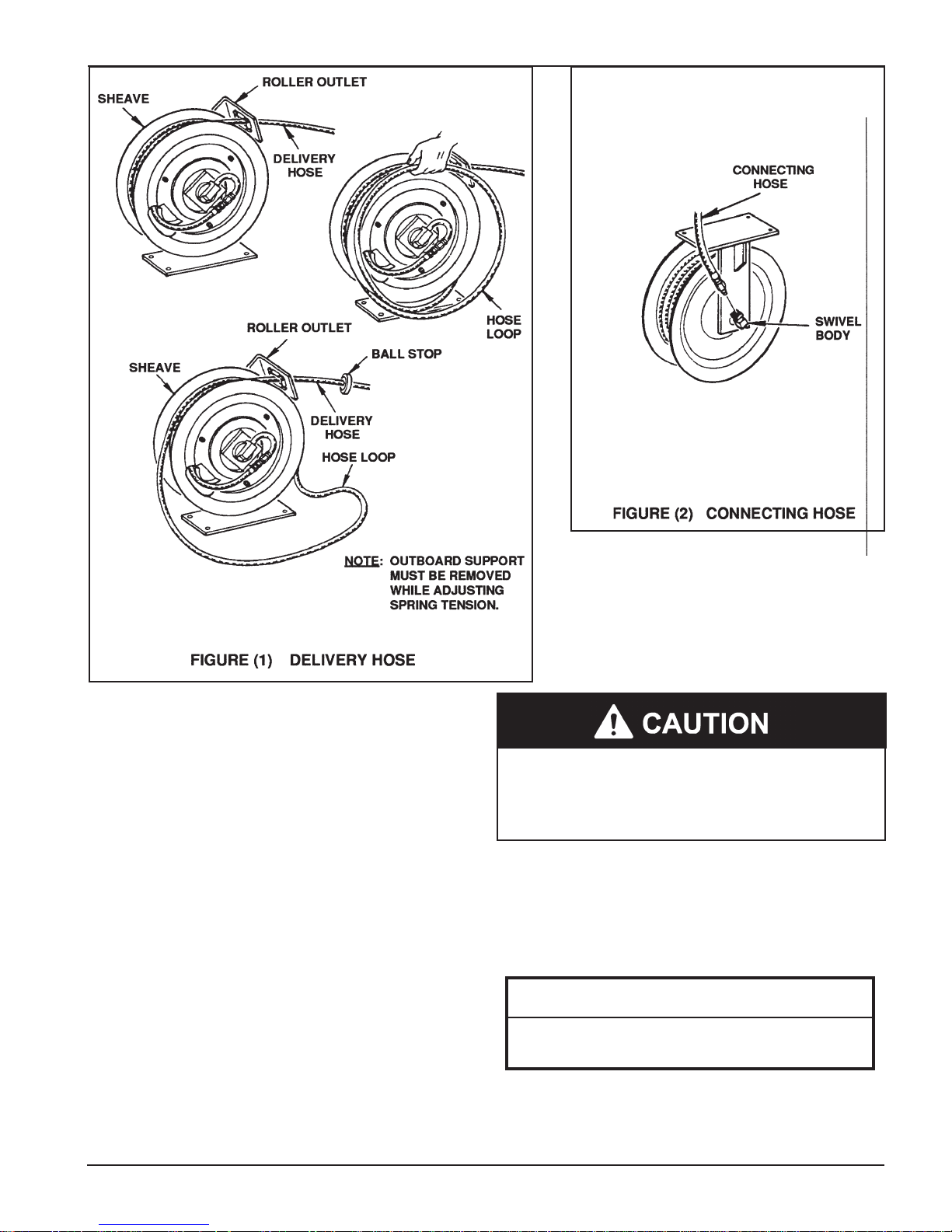
DELIVERY HOSE
DELIVERY HOSE INSTALLATION (MAXIMUM
SPRING TENSION)
For smoother operation during retraction and to increase hose
life, “detaic” hose by wiping entire hose length with a light lubricating oil before installing on reel.
Assemble outlet adapter to hose and tighten securely. Use
teflon tape on threads to prevent leaks.
Form 404031
To prevent damaging hose connections and/or
components when pulling hose from reel, pull on the hose
itself and not on the control valve or swivel. Do not pull or
jerk on the hose when fully withdrawn from the reel.
From open side of reel (with outside support removed), loop
entire length of hose onto reel in a clockwise direction. Pull hose
out through roller outlet to wind power spring. When hose is
completely extended, latch reel to prevent it from unwinding.
Continue to add loops of hose and pull out
hose until power spring winds tight.
IMPORTANT
INSTRUCTIONS
Perform the following instructions as stated to
correctly set the power spring for maximum tension.
Allow reel to retract two full revolutions and latch
reel. Carefully unloop remaining hose from reel.
Page Number - 3
To order call 1-800-548-1191 or visit www.partdeal.com - info@partdeal.com
 Loading...