

Page 1
Page 2

Table of Contents
i
Page 3

ii
Page 4

iii
Page 5

iv
Page 6

Introduction
Ford’s Commitment to You
At Ford Motor Company, excellence is the
continuous commitment to achieve the best result
possible. It is dedication to learning what you want,
determination to develop the right concept, and
execution of that concept with care, precision, and
attention to detail. In short, excellence means being
the standard by which others are judged.
Our Guiding Principles
Quality comes first. For your satisfaction, the
❑
quality of our products and services must be our
number one priority.
You are the focus of everything we do. Our
❑
work must be done with you in mind,
providing better products and services than our
competition.
Continuous improvement is essential to our
❑
success. We must strive for excellence in
everything we do: in our products — in their
safety and value — and in our services, our
human relations, our competitiveness, and our
profitability.
Employee involvement is our way of life.
❑
We are a team. We must treat one another
with trust and respect.
Dealers and suppliers are our partners. We
❑
must maintain mutually beneficial relationships
with dealers, suppliers, and our other business
associates.
Integrity is never compromised. Our conduct
❑
worldwide must be pursued in a manner that is
socially responsible and commands respect for
its integrity and for its positive contributions to
society.
1
Page 7
ThingstoKnowAboutUsingThis
Guide
Congratulationsonthepurchaseofyournew
vehicle.Thisguidehasinformationaboutthe
equipmentandtheoptionsforyournewvehicle.
Youmaynothaveboughtalloftheoptions
availabletoyou.Ifyoudonotknowwhich
informationappliestoyourvehicle,talktoyour
dealer.
Thisguidedescribesequipmentandgives
specificationsforequipmentthatwasineffectwhen
thisguidewasapprovedforprinting.Fordmay
discontinuemodelsorchangespecificationsor
designwithoutanynoticeandwithoutincurring
obligation.
2
NOTESandWARNINGS
NOTESgiveyouadditionalinformationaboutthe
subjectmatteryouarereferencing.
WARNINGSremindyoutobeespeciallycarefulin
thoseareaswherecarelessnesscancausedamageto
yourvehicleorpersonalinjurytoyourself,your
passengersorotherpeople.Pleasereadall
WARNINGScarefully.
WARNING
Page 8

Finding Information in This Guide
After you have read this guide once, you will
probably return to it when you have a specific
question or need additional information. To help
you find specific information quickly, you can use
the Quick Index or the Index.
The Quick Index at the end of the book provides
a page number following each item which indicates
where detailed information can be found.
To use the Index, turn to the back of the book
and search in the alphabetical listing for the word
that best describes the information you need. If the
word you chose is not listed, think of other related
words and look them up. We have designed the
Index so that you can find information under a
technical term.
Canadian Owners — French Version
French Owner Guides can be obtained from your
dealer or by writing to Ford Motor Company of
Canada, Limited, Service Publications, P.O. Box
1580, Station B, Mississauga, Ontario L4Y 4G3.
The Lincoln Commitment
The Lincoln Commitment is more than the prestige
of owning a superior luxury automobile, it is a
comprehensive owner benefits package that is
designed to provide you with services to support
your every driving need. Refer to the Lincoln
Commitment brochure for more information.
Your Maintenance Schedule and
Record Booklet
The Maintenance Schedule booklet lists the services
that are most important for keeping your vehicle in
good condition. A record log is also provided to
help you keep track of all services performed.
3
Page 9

About the Warranties
Your vehicle is covered by three types of warranties:
Basic Vehicle Warranty, Extended Warranties
on certain parts, and Emissions Warranties.
Read your Warranty Information Booklet carefully to
find out about your vehicle’s warranties and your
basic rights and responsibilities.
If you lose your Warranty Information Booklet, you
can get a new one free of charge. Contact any Ford
or Lincoln-Mercury dealer, or refer to the addresses
and phone numbers on the first page of this
Owner’s Guide.
More Protection for Your Vehicle
You can get more protection for your new car or
light truck by purchasing a Ford Extended Service
Plan (Ford ESP). Ford ESP is the only extended
service program with the Ford name on it and the
only service contract backed by Ford Motor
Company.
4
Ford ESP is an optional service contract, backed and
administered by Ford. It provides:
protection against repair costs after your Bumper
❑
to Bumper Warranty expires;
and
other benefits during the warranty period (such
❑
as: reimbursement for rentals; coverage for
certain maintenance and wear items).
You may purchase Ford ESP from any participating
Ford Motor Company dealer. There are several Ford
ESP plans available in various time-and-mileage
combinations. Each plan can be tailored to fit your
own driving needs, including reimbursement
benefits for towing and rental. (In Hawaii, rules
vary. See your dealer for details.)
Page 10

When you buy Ford ESP, you receive peace-of-mind
protection throughout the United States and
Canada, provided by a network of more than 5,100
participating Ford Motor Company dealers.
NOTE: Repairs performed outside the United States
and Canada are not eligible for ESP coverage.
This information is subject to change. Ask your
dealer for complete details about Ford ESP coverage.
Breaking Your Vehicle In
Your new vehicle goes through an adjustment or
break-in period during the first 1,000 miles
(1,600 km) that you drive it. During the break-in
period, you need to pay careful attention to how
you drive your vehicle.
Avoid sudden stops. Because your vehicle has
❑
new brake linings, you should take these steps:
—Watch traffic carefully so that you can
anticipate when to stop.
—Begin braking well in advance.
—Apply the brakes gradually.
The break-in period for new brake linings
lasts for 100 miles (160 km) of city driving
or 1,000 miles (1,600 km) of highway
driving.
Use only the type of engine oil that Ford
❑
recommends. See Engine oil recommendations
in the Index. Do not use special “break-in” oils.
5
Page 11

Instrumentation
The instrument panel (dashboard) on your vehicle is
divided into several different sections. The
illustrations on the following pages show the major
parts of the instrument panel that are described in
this chapter. Some items shown may not be on all
vehicles.
The main controls for the climate control system,
clock, and radio are on the instrument panel.
If you have radio transmitting equipment in your
vehicle, be aware that it can interfere with your
vehicle’s electrical system and may cause the
instrumentation and/or convenience products to
have temporary, abnormal operation.
NOTE: Any cleaner or polish that increases the
gloss (shine) of the upper part of the instrument
panel should be avoided. The dull finish in this area
is to help protect the driver from undesirable
windshield reflection.
7
Page 12
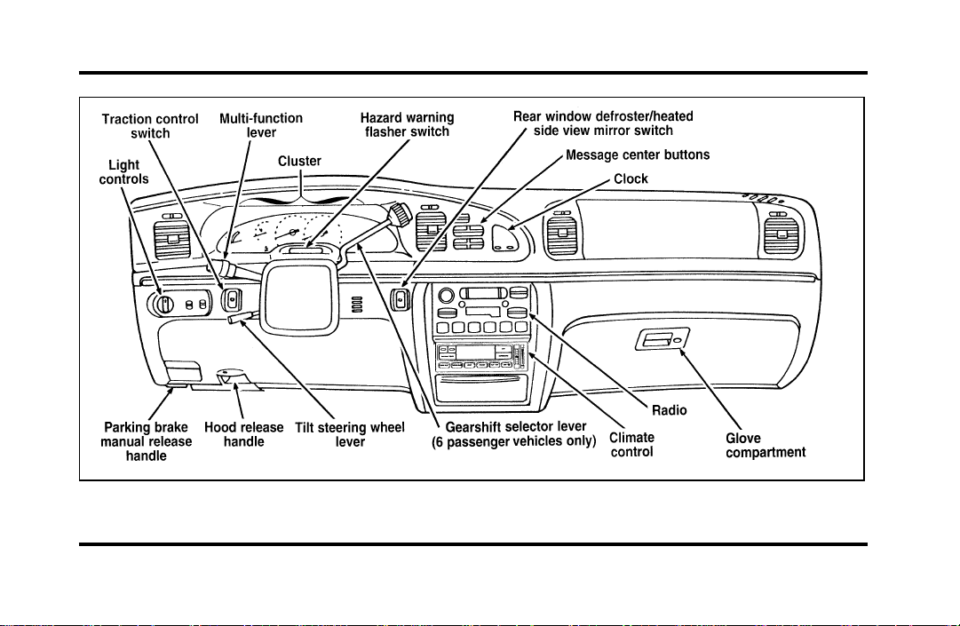
Instrument panel
8
Page 13
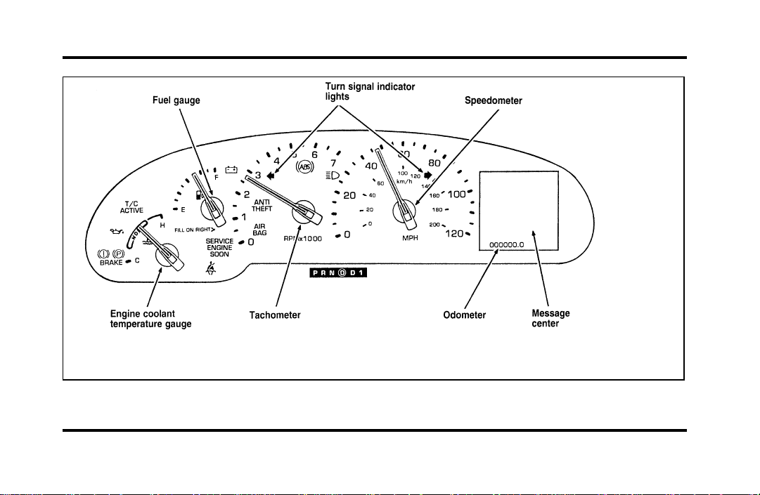
Instrument cluster
9
Page 14
The following warning lights and gauges are on the
instrument cluster. All of the warning lights and
gauges alert you to possible problems with your
vehicle.
Indicator Lights and Chimes
Safety Belt Warning Light and Chime
This warning light and chime remind you to fasten
your safety belt. The following conditions will take
place:
If the safety belt is not buckled when the
❑
ignition is turned to the ON position, the chime
will turn on for four (4) to eight (8) seconds
and the light will come on for one to two
minutes.
If the safety belt is buckled while the light is on
❑
and the chime is sounding, both the light and
chime will turn off.
10
If the safety belt is buckled before the ignition
❑
is turned to the ON position, neither the light
nor the chime will come on.
Brake System Warning Light
The warning light for the brakes can show two
things — that the parking brake is not fully
released, or that the brake fluid level is low in the
master cylinder reservoir. If the fluid level is low,
the brake system should be checked by your dealer
or a qualified service technician.
Page 15
Thislightcomesonwhentheparkingbrakeisset,
orifitisnotset,itcomesonbrieflywhenyou
turntheignitiontotheSTARTposition.Itnormally
goesoffshortlyaftertheenginestartsandyou
releasetheparkingbrake.Ifthelightstaysonafter
youhavefullyreleasedtheparkingbrake,havethe
hydraulicbrakesystemservicedbyyourdealerora
qualifiedservicetechnician.
WARNING
TheBRAKElightindicatesthatthe
brakesmaynotbeworkingproperly.
Havethebrakescheckedimmediately.
Anti-LockBrakeSystemWarningLight
Thislightcomesonforafewsecondswhenyou
turntheignitionkeytotheSTARTposition.It
shouldgooffshortlyaftertheenginestarts.Ifit
staysonlongerthanfive(5)seconds,itindicates
thatyouranti-lockbrakesystemmaynotbe
workingproperly.Normalbrakingisnotaffected
unlesstheBRAKEsystemwarninglightalsoremains
onforlongerthansix(6)seconds.Youshouldhave
yourvehicleservicedimmediatelybyyourdealeror
qualifiedservicetechniciantorestorethebenefitsof
theanti-lockfeature.SeeAnti-lockbrakesinthe
Indexformoreinformation.
11
Page 16
Engine Oil Pressure Warning Light
This light indicates the engine’s oil pressure, not the
oil level. However, if your engine’s oil level is low,
it could affect the oil pressure. The light will come
on briefly when you turn your key to the START
and ON position. The light should stay off when
the engine is running with normal oil pressure. If
the light comes on while the engine is running, you
have lost oil pressure and continued operation will
cause severe engine damage.
12
If you lose engine oil pressure:
1. Pull off the road as soon as safely possible.
2. Shut off the engine immediately or severe
engine damage could result.
3. Check the engine’s oil level, following the
instructions on checking and adding engine oil,
see Engine Oil in the Index. If you do not
follow these instructions, you or others could
be injured. To assure an accurate reading, your
car should be on level ground.
4. If the level is low, add only as much oil as
necessary before you start the engine again. Do
not overfill. Do not operate the engine if the
light is on, regardless of the oil level. Contact
your nearest dealer for further service actions.
For more information about adding oil, see Adding
engine oil in the Maintenance and Care chapter.
Page 17
Traction ControlH Active Light
(If equipped)
This light comes on when the Traction ControlH
system begins applying and releasing the brakes and
adjusting the engine characteristics to limit a
wheelspin condition.
It will be lit for a minimum of six seconds or for
the duration of the Traction ControlH event.
Charging System Light
This light indicates that your battery is not being
charged and that you need to have the electrical
system checked.
13
Page 18
This light illuminates every time you turn the
ignition to the ON or START position (engine off).
The light should go off when the engine starts and
the alternator begins to charge.
If the light stays on or illuminates when the engine
is running, have the electrical system checked as
soon as possible.
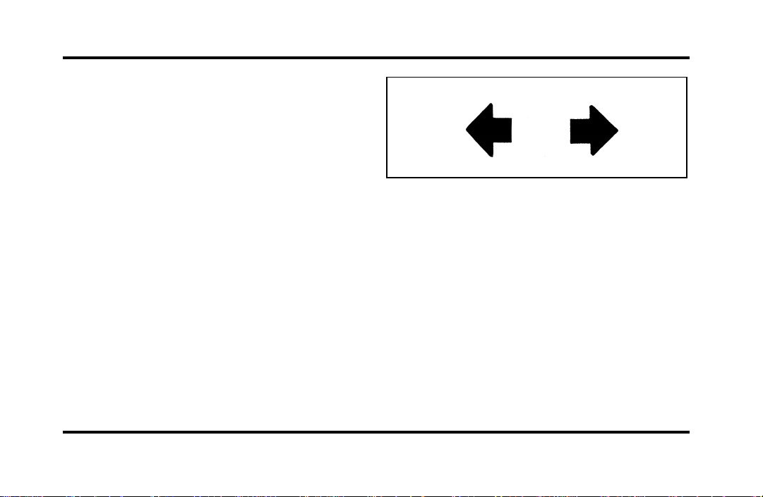
Turn Signal Indicator Lights
When you push the turn signal lever up before
making a right turn, the right side arrow on the
instrument panel flashes.
When you push the turn signal lever down before
making a left turn, the left side arrow on the
instrument panel flashes.
Usually, the turn signals turn off automatically after
you turn your vehicle. If the turn signal continues
to flash after you have made the turn, push the
lever back to the OFF position.
14
If one or both of your turn indicators do not flash
or stay on continuously, have them serviced as soon
as possible. In the meantime, be sure to use the
accepted hand signals.
Service Engine Soon Warning Light
This light illuminates when the engine’s Emission
Control System requires service. It will also
illuminate when the ignition key is in the ON
position and the engine is off.
Page 19
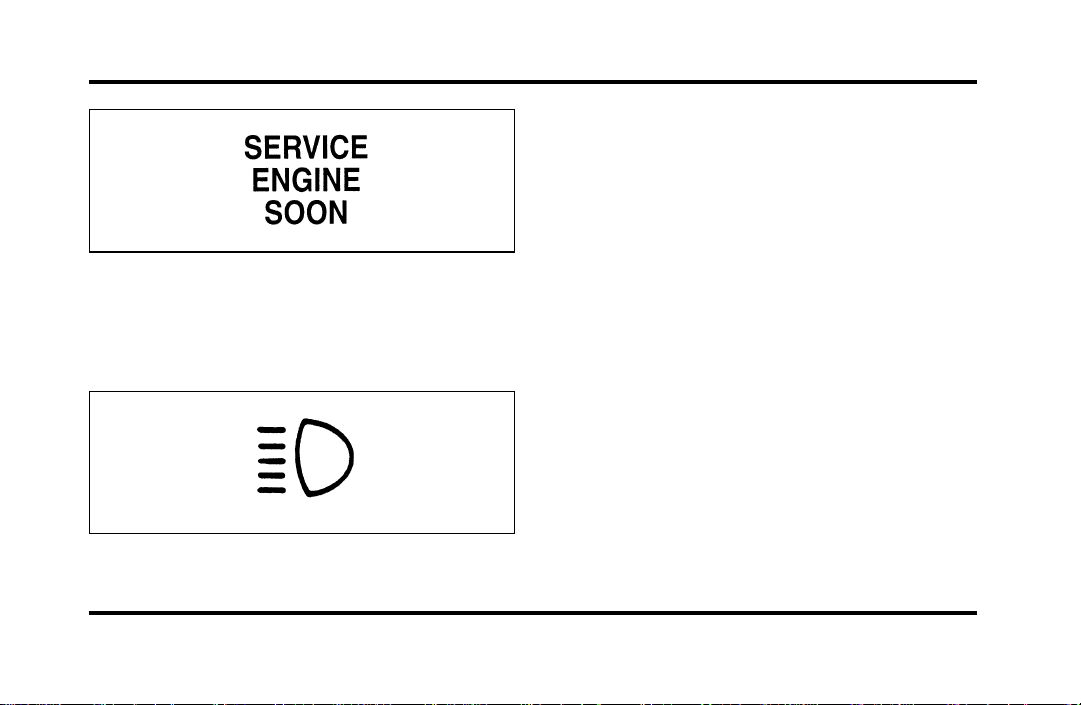
High Beam Light
This light illuminates when the headlamps are
turned to high beam or when you flash the lights.
Chime for Headlamps On
This chime sounds if the driver or any passenger
door is open when the parking lamps or headlamps
are on. The chime sounds until you close the door,
turn off the lamps or turn the ignition to the ON
position.
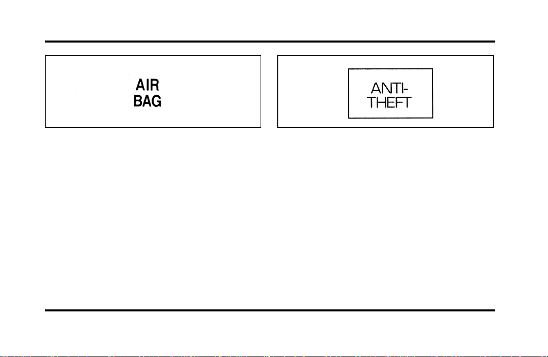
Air Bag Readiness Light
The air bag system uses a readiness light and a tone
to indicate the condition of the system. The
readiness light is in the instrument cluster. When
you turn the ignition key to the ON position, this
light will light up for six (6) seconds and then turn
off. This indicates that the system is operating
normally. NOTE: Regularly scheduled maintenance
of the air bag system is not required.
15
Page 20
If the light fails to illuminate, continues to flash,
remains on, or you hear a beeping sound, have the
system serviced at your Ford or Lincoln-Mercury
dealer immediately.
Anti-Theft Alarm Light (If equipped)
This light flashes on and off when the ignition is
turned to the OFF position and any door is opened.
As soon as you lock the doors, the light glows
steadily. Within 30 seconds of closing all the doors,
the light goes out. This indicates that the alarm
system is armed.
16
See Anti-Theft System in the Controls and Features
chapter for more information.
The Instrument Cluster
In addition to warning lights, the instrument cluster
has a message center/odometer, a speedometer,
tachometer, fuel and coolant temperature gauges.
Page 21

Odometer
The odometer tells you the total number of miles
(kilometers) your vehicle has been driven.
If the odometer displays the word Error, please
contact your dealer for service.
Speedometer
The speedometer tells you how many miles
(kilometers) per hour your vehicle is moving.
Tachometer
The tachometer displays the approximate engine
revolutions per minute (rpm), or how fast the
engine is running.
You can drive your vehicle at most rpm points on
the tachometer but you must stay out of the red
zone.
If you drive with the tachometer in the red zone,
you may damage the engine.
Engine Coolant Temperature Gauge
This gauge indicates the temperature of the engine
coolant, not the coolant level. If the coolant is not
at its proper level or mixture, the gauge indication
will not be accurate.
The pointer moves from the C (cold) mark into the
NORMAL band as the engine coolant warms up. It
is acceptable for the pointer to fluctuate within the
NORMAL band under normal driving conditions.
Under certain driving conditions such as, heavy stop
and go traffic, or driving up hills in hot weather,
the pointer may indicate at the top of the NORMAL
band.
If, under any circumstances, the pointer moves
above the NORMAL band, the engine is overheating
and continued operation may cause engine damage.
If your engine overheats:
1. Pull off the road as soon as it is safely possible.
2. Turn off the engine.
17
Page 22

3. Let the engine cool. DO NOT REMOVE
COOLANT SYSTEM FILL CAP UNTIL THE
ENGINE IS COOL.
4. Check the coolant level following the
instructions on checking and adding coolant to
your engine, see Engine Coolant in the Index.
If you do not follow these instructions, you or
others could be injured.
If the coolant continues to overheat, have the
coolant system serviced as soon as possible.
Fuel Gauge
The fuel gauge displays approximately how much
fuel you have in the fuel tank. The ignition switch
must be in the OFF position while filling the tank
with at least three gallons (11 liters) for the fuel
gauge to indicate the new level. If the ignition is
left ON or less than 3 gallons (11 liters) of fuel are
added the fuel gauge will not immediately indicate
the new fuel level. The gauge will gradually correct
itself to indicate the true fuel level.
18
The Electronic Message Center
(M/C)
The Electronic Message Center only works when
the ignition is in the ON position.
Each time the M/C is powered the display goes
through a self test by displaying the PLEASE
FASTEN SEATBELT message. This self test is used
to stabilize the systems before reporting the status
to you.
The message center tells you about the condition of
your vehicle by two methods:
operator selectable features
❑
continuous warning reporting of monitored
❑
systems
Page 23
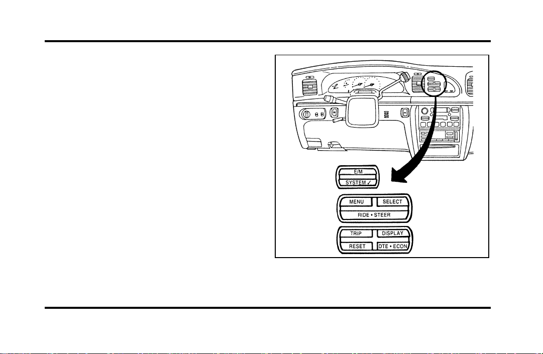
You can select different features for the M/C to
display by using the message center control buttons
located to the right of the instrument cluster. You
will hear a tone when you press one of these
buttons. However, if the M/C detects a warning
from any of the monitored systems, then the M/C
will display the appropriate warning message.
Operator Selectable Features
Cluster Control Buttons and Message Center
Control Buttons
19
Page 24

These features are controlled by the message center
(M/C) control buttons located to the right of the
instrument cluster.
System Check
Pressing the SYSTEM CHECK button causes the
M/C to cycle through a status of each of the
systems being monitored. For each of the monitored
systems, the M/C will indicate either an OK
message or a warning message for three seconds.
The sequence of the system check report is as
follows:
Washer Fluid Level
❑
Ride Control
❑
Oil Level
❑
Engine Coolant Level
❑
Voltage Level
❑
Engine Temperature
❑
20
Doors Closed (Driver and Right Side)
❑
Trunk Closed
❑
Exterior Lamps (Head, Front Turn, Brake and
❑
Tail)
Distance to Empty
❑
Fuel Level
❑
Traction Control (if equipped)
❑
System Warnings
System warnings alert you to possible problems or
malfunctions in your vehicle’s operating systems.
There are up to 18 warning messages which can be
displayed by the M/C to show the status of the
monitored systems. The M/C will display the last
selected feature if there are no more warning
messages. This allows you to use the full
functionality of the M/C after you acknowledge the
warning by pressing the RESET button and clearing
the warning message.
Page 25
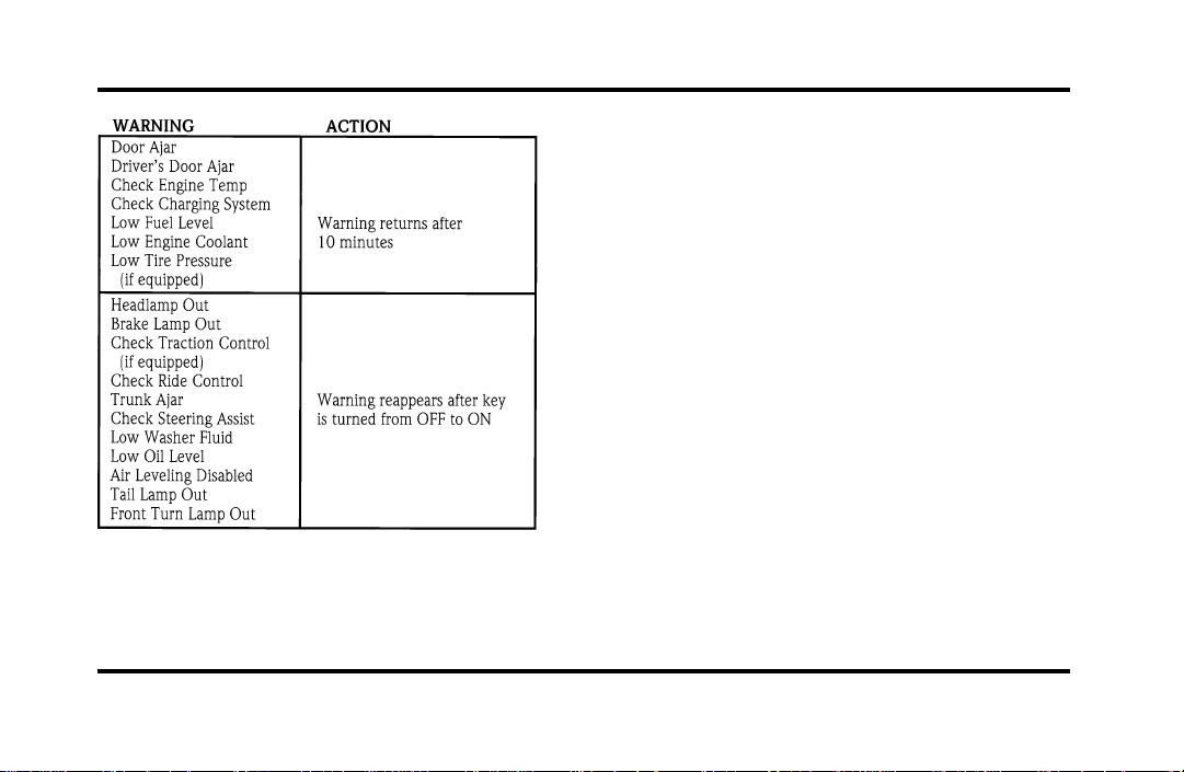
Warning messages that have been reset are divided
into two categories. They will reappear on the
display ten minutes from the reset or they will not
reappear until an ignition OFF-ON cycle has been
completed. This reappearing of warning messages is
a reminder that these warning conditions still exist
within the vehicle.
E/M
A press of this button allows you to change the
M/C and the Electronic Climate control unit from
English to Metric Units. When you press this button
all displays change from English to Metric or Metric
to English units. The displays remain in the units
you have chosen until you change them again even
after you turn off the vehicle and start it again.
TRIP
Pressing this button will display the first of two trip
odometers. Pressing it again will display the second
Trip Odometer. Pressing RESET will clear ony that
Trip odometer which is displayed.
21
Page 26

DTE/ECON
Pressing this button a first time will display
approximately how many miles you can drive before
you run out of fuel, or in other words the Distance
To Empty (DTE). To ensure accuracy, turn the
ignition OFF when you fill the tank.
Pressing this button a second time will allow you to
display your Average Fuel Economy in miles/gallon
or liters/100 kilometers. Your M/C computes this
figure using the distance traveled and rate of fuel
used information. If you want to reset this feature,
press the RESET button while the Average Fuel
Economy feature is displayed.
NOTE: DTE (Distance to Empty) is calculated using
a “Running Average Fuel Economy” initialized by
the factory. This value is not the same as the
Average Fuel Economy Display. The Running
Average Economy is based on more than 500 miles
(800 km) of driving history. Also the factory default
for Running Average Economy is reinitialized if the
battery is disconnected.
22
If the FUEL LEVEL ERROR message is displayed
this means that there is a problem with the fuel
indication system and you should contact your
dealer for service as soon as possible.
RESET
A press of the RESET button will allow you to reset
the current feature displayed. Warnings, Average
Fuel Economy, and Trip odometers are the only
features which respond to the RESET button.
Distance to Empty (DTE), RIDE/STEER and MENU
are unaffected by pressing the RESET switch.
DISPLAY
Pressing this button will cause the message center
display to turn off. Pressing it again will cause the
display to come on again. Warnings override an off
display and must be reset in order for the display to
be off again.
Page 27

RIDE/STEER
Pressing this button once will allow you to adjust
your RIDE CONTROL settings, between NORMAL,
PLUSH and FIRM. The settings are changed by
pressing the SELECT button while RIDE CONTROL
is displayed.
Pressing the RIDE/STEER button a second time will
allow you to adjust the STEERING EFFORT settings
between NORMAL, LOW, and HIGH. The settings
are changed by pressing the SELECT button while
STEERING EFFORT is displayed.
NOTE: The combination of FIRM RIDE CONTROL
and LOW STEERING EFFORT is undesirable and
cannot be selected.
MENU
Pressing this button will allow you to change
various convenience settings throughout the vehicle.
The settings for each feature are changed by
pressing the SELECT button.
Pressing the MENU button once will allow you to
enable or disable the EXPRESS WINDOW feature.
This feature allows one tap down operation on the
driver’s window using the window switch on the
driver’s door armrest.
Pressing MENU again will allow you to enable or
disable the AUTO DOOR LOCK feature. This
feature automatically locks all doors when the driver
shifts out of PARK, all doors are closed, the driver’s
seat is occupied, and the vehicle is traveling over
three mph (5 km/h).
23
Page 28

Pressing MENU again will allow you to enable or
disable the HORN CHIRP feature. When HORN
CHIRP is ON the horn will briefly sound when the
Remote Entry Key Fob LOCK button is pressed.
This verifies the doors have been locked and the
ANTI-THEFT system has been armed (if equipped).
Pressing MENU again will allow you to enable or
disable the SEAT ACCESS feature. When ON, the
driver’s seat will move back 2 inches (5 cm) or to
end of seat travel when the vehicle is turned off
and the ignition key is removed. Upon the driver
entering the vehicle and closing the door, the seat
will move forward to its previous position.
24
Pressing MENU again will allow you to enable or
disable the REVERSE MIRRORS feature. When ON,
the outside rearview mirrors tilt down when the
gearshift is placed in R (Reverse). This provides for
an improved view of the side of the vehicle and
curb area when backing up. When you shift out of
REVERSE the mirrors return to their previous
positions.
Page 29
Electronic Sound Systems
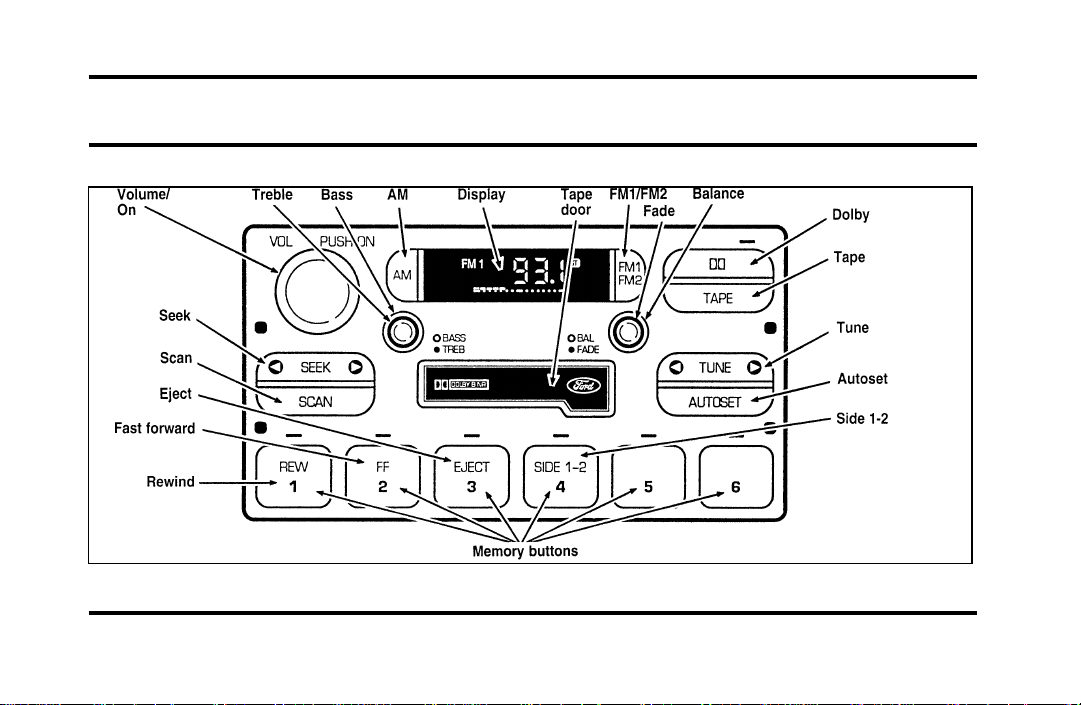
Luxury Audio System (Analog)
25
Page 30
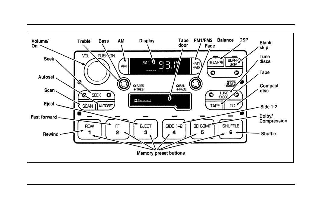
Luxury Audio System (Digital)
26
Page 31

Luxury Audio System
Using the Controls on Your New Radio
How to turn the radio on and off
Press the “VOL/PUSH ON” knob to turn the radio
on. Press again to turn it off.
How to adjust the volume
Turn the “VOL/PUSH ON” knob clockwise to
increase the volume and counter-clockwise to
decrease the volume.
NOTE: If the volume is set above a certain level
when the ignition is turned off, the volume level
will reset to a “nominal” listening level when the
ignition switch is turned back on. However, if the
radio is turned off with the “VOL/PUSH ON” knob,
the volume will not reset and will stay at the same
level when the radio is turned back on.
Selecting the AM or FM frequency band
Push the “AM” or “FM1/FM2” button to select the
desired frequency band. Pushing the “FM1/FM2”
button more than once will alternate between FM1
and FM2. These functions are used with the
memory preset buttons described under How to
tune radio stations.
How to tune radio stations
There are four ways for you to tune in a particular
station. You can use the “TUNE”, “SEEK”, “SCAN”
or memory buttons.
Using the “TUNE” function
❑
You can change the frequency up or down one
increment at a time by pressing and releasing
either the left (b) or right (a) side of the
“TUNE” or “TUNE DISCS” button. To change
frequencies quickly, press and hold down either
the right or left side of the button.
27
Page 32

Manual tuning adjusts your radio to any allowable
broadcast frequency, whether or not a station is
present on that frequency. (See All About Radio
Frequencies in this section.)
Using the “SEEK” function
❑
Press the rightaside of the “SEEK” button to
select the next listenable station up the
frequency band. Press the leftbside of the
button to select the next listenable station down
the frequency band. By holding the button
down, listenable stations can be passed over to
reach the desired station.
Using the “SCAN” function
❑
Pressing the “SCAN” button will begin the scan
mode up the frequency band, stopping on each
listenable station for approximately five seconds.
To stop the scan mode on the presently
sampled station, press the “SCAN” button again.
28
Setting the station MEMORY PRESET buttons
❑
Your radio is equipped with 6 station memory
buttons. These buttons can be used to select up
to 6 preset AM stations and 12 FM stations (6
in FM1 and 6 in FM2)
1. Select a band, then select a frequency.
2. Press one of the memory buttons and hold
until the sound returns and the lamp above the
memory button lights up. That memory button
is now set.
3. Follow the above steps for each memory preset
button.
NOTE: Custom memory presets can be recalled
using the keyless entry system. See Memory Profile
System in the Features chapter.
Page 33

Using the Automatic Memory Store feature
(“AUTOSET”)
If the memory buttons have been set, either by
using the Auto Memory Load feature or if you have
set them manually, the system is prepared to let
you use a convenient feature called Automatic
Memory Store.
With Auto Memory Store, you can continually set
strong stations into your memory buttons without
losing your originally set stations. Your radio will
automatically set your memory buttons to the strong
local stations.
Activate Auto Memory Store by pushing the
“AUTOSET” button once. Your radio will set the
first six strong stations of the band you are in (AM,
FM1 or FM2) into the memory buttons. The display
will flash “AUTO” and display the autoset icon “A”
while the stations are being set in the memory
buttons.
NOTE: If there are less than six strong stations in
the frequency band, the remaining unfilled buttons
will store the last strong station detected on the
band. After all stations have been filled, the radio
will begin playing the station stored on memory
button 1.
To deactivate the Auto Memory Store mode and
return to the manually-set memory button stations,
simply push the “AUTOSET” button. Display will
show “AUTO” then “OFF”. The next time Auto
Memory Store is activated on that band, the radio
will store the next set of six strong stations.
29
Page 34

Adjusting the tone balance of your radio
Increasing or decreasing bass and treble
❑
response
Push the “BASS/TREB” popout knob to gain
access to the bass and treble controls. Bass
control allows you to adjust the lower, bass
frequencies to your preference. The outer ring
of the “BASS/TREB” knob adjusts the bass (turn
clockwise to increase bass; counterclockwise to
decrease bass).
Treble control allows you to adjust the higher,
treble frequencies of your radio to your
preference. The inner ring of the “BASS/TREB”
knob adjusts the treble (turn clockwise to
increase treble; counterclockwise to decrease
treble).
30
Adjusting speaker balance and speaker fader
❑
Push the “BAL/FADE” popout knob to gain
access to the speaker balance and fader controls.
Balance control allows you to adjust the sound
distribution between the right and left speakers.
The outer ring of “BAL/FADE” knob adjusts the
speaker balance control. (Turn clockwise to shift
the sound to the right speakers, and turn
counterclockwise to shift the sound to the left
speakers.)
Fade control allows you to adjust the sound
distribution between the front and rear speakers.
The inner ring of the “BAL/FADE” knob adjusts
the speaker fader. (Turn clockwise to shift the
sound to the rear speakers, and turn
counterclockwise to shift the sound to the front
speakers.)
Page 35

Using the Digital Signal Processing
(DSP) Feature
Push the “(aDSPb)” button to activate the
feature. The display will indicate which signal mode
is in effect. To change the signal mode press either
the left (b) or right (a) side of the selector
button (located under the “(aDSPb)” button).
The following signal modes may be selected:
1. “HALL” — Rectangular concert hall capacity of
about 2,000.
2. “CHURCH” — Church with a high vault.
3. “JAZZ” — Jazz club with clearly reflected
sounds.
4. “STADIUM” — Outdoor stadium with a
capacity of about 30,000.
5. “NEWS” — “Voice-only” type of sound with a
limited audio band.
To deactivate the DSP feature, press the
“(aDSPb)” button again.
Delayed Accessory Feature
(If Equipped)
If the ignition is turned off while the radio is on,
the radio will continue to play for up to ten
minutes or until a door is opened.
Speaker Locations
Your Ford JBL sound system is equipped with a
total of ten speakers: two speakers in each of the
four doors and two subwoofers located in the rear
package tray.
Your Antenna
Antennas for both AM and FM reception are hidden
in the back glass of your vehicle. There is an
internal antenna module that will switch between
AM and FM, when bands are changed, for
maximum reception performance.
31
Page 36

NOTE: Do not attempt to adapt any other type of
antenna system to your audio system.
Using the Controls of Your Cassette
Tape Player
NOTE: Radio power must be on to use the cassette
tape player.
How to insert a tape
Your cassette tape player is equipped with power
loading. Once you insert a tape and push slightly
(with the open edge to the right), the loading
mechanism draws the tape the rest of the way in
and play will begin after a momentary tape
tightening process. Display indicates “TAPE” while
tape is playing.
If the player is in the tape mode but not in play,
pressing the “TAPE” button will activate play. If the
“TAPE” button is pressed with no tape inserted, the
display will flash “NO TAPE”.
32
How to locate a desired track on the tape
There are six ways to quickly locate a desired
selection on the tape. You can use the fast forward,
rewind, Blank Skip, “SEEK”, “SCAN” or “SIDE 1-2”
functions. Following are brief descriptions of each:
Fast forwarding the tape
❑
To fast forward the tape, press the “FF” button.
The radio will play while the tape is in fast
forward. The light above the “FF” button will
blink while in the fast forward mode. Press
“FF” again or press the “TAPE” button to stop
fast forwarding. At the end of the tape, the
direction automatically reverses and plays the
other side of the tape.
Page 37

Rewinding the tape
❑
To rewind the tape, press the “REW” button.
The radio will automatically begin playing while
the tape is rewinding. The light above the
“REW” button will blink while in the rewind
mode. Press “REW” again or press the “TAPE”
button to stop rewinding.
Using the “SEEK” function with your cassette
❑
tape player
While in the tape mode, push the rightaside
of the “SEEK” button to seek forward to the
next selection on the tape. Push the left
side to restart a currently playing tape selection.
Using the “Blank Skip” function with your
❑
cassette tape player
Press the “Blank Skip” button to activate the
blank skip mode. After approximately 20
seconds of blank program, the tape will seek
forward to the next program.
b
Using the “SCAN” function with your cassette
❑
tape player
Pushing the “SCAN” button will begin the
forward scan mode on the tape currently
playing, stopping on each tape selection for
approximately eight seconds.
To stop the scan mode on the presently sampled
tape selection, press the “SCAN” button or the
“TAPE” button.
How to change the side of the tape being played
❑
The alternate side of the tape can be selected
by pressing the “SIDE 1-2” button.
How to eject the tape
To stop the tape and eject the cassette, press the
“EJECT” button. The tape will eject only when in
the tape mode. The cassette cannot be ejected
when the radio is playing an “AM” or “FM”
station. The system will revert to radio mode when
the cassette is ejected.
33
Page 38

How to store the tape
Press the “AM/FM” button to stop the tape player
and resume radio play.
Using the DolbyH B noise reduction
feature
NOTE: Noise reduction system manufactured under
license from Dolby Labs Licensing Corporation.
“Dolby” and double-D symbol are trademarks of
Dolby Laboratories Licensing Corporation.
Push the k button to activate. When activated,
the light above the k button will be illuminated.
Tape error messages
Your cassette tape player is equipped to diagnose
certain problems you may experience. Error codes
are as follows:
TD E1 — Radio tries to change sides of tape 3
times in a 10 second span. Push “EJECT” and try
another tape. If problem persists, refer problem to
qualified personnel for service.
34
TD E2 — Tape eject failure. Radio tries to eject
tape and it will not eject. Push “EJECT” to eject
tape. If the tape will not eject, refer problem to
qualified personnel for service.
TD E3 — Loading error. Push “EJECT” to eject
tape. Reload tape. If the same error code appears in
the display, try another tape.
Tips on Caring for the Cassette Player
and Tapes
In order to keep your cassette tape player
performing the way it was meant to, read and
follow these simple precautions:
Using a Ford Cassette Cleaning Cartridge or
❑
equivalent to clean the tape player head after
10-12 hours of play will help maintain the best
playback sound and proper tape operation.
Only cassettes that are 90 minutes long or less
❑
should be used. Tapes longer than 90 minutes
are thinner and subject to breakage or may jam
the tape player mechanism.
Page 39

Protect cassettes from exposure to direct
❑
sunlight, high humidity and extreme heat or
cold. If they are exposed to extreme conditions,
allow them to reach a moderate temperature
before playing.
If a tape is loose inside the cassette, tighten it
❑
before playing by putting your finger or a pencil
into one of the holes and turning the hub until
the tape is tight.
Loose labels on cassette tapes can become
❑
lodged in the mechanism. Remove any loose
label material before inserting a cassette.
Do not leave a tape in the cassette tape player
❑
when not in use. High heat in the vehicle can
cause the cassette to warp.
Ford 6-CD Changer
Introduction
The Ford 6-CD Changer is mounted in your console
and holds 6 CDs, all controlled by using buttons on
your Luxury Audio System.
Be sure to read all of the information provided on
the following pages to get the most out of this
system.
35
Page 40

Loading Instructions
1. Open Compact Disc Changer unit by sliding
door to the right (Figure 1).
Figure 1
36
2. Push the i button to eject the disc “magazine”
(holds 6 discs) (Figure 2).
Figure 2
Page 41

3. Load discs into the disc magazine slots
(numbered 1 through 6) one at a time with
labeled surfaces upward, starting with bottom
slot number 1 (Figure 3).
4. Insert loaded disc magazine into chamber unit
with the arrow on top of the disc magazine
pointing toward the changer (Figure 4). Make
sure magazine is fully inserted into changer.
Figure 4
Figure 3
NOTE: To remove one or more compact disc(s)
from the disc magazine, push the corresponding
lever(s) to the back. Disc(s) will partially come out
for easy removal.
5. Close unit by sliding changer panel door to the
left.
37
Page 42

The Compact Disc Changer unit is now ready to
play using the controls of your Luxury Audio
System.
How to Operate the Ford 6-CD
Changer Using the Controls on the
Radio
If your vehicle is equipped with the Ford 6-CD
Changer System, you can operate it through the
controls of your Luxury Audio System.
Several of the controls on the radio operate in the
same manner in CD mode as they do in radio or
cassette mode: turning the power on, volume
control and adjusting the bass, treble, speaker
balance or fade.
38
How to begin CD Changer play
NOTE: Radio power must be on to operate the
Compact Disc Changer.
Push the “CD” button to begin CD play. The CD
Changer will automatically begin playing the first
track (selection) of the first disc loaded in the unit.
The display will indicate “CD-##” for disc number
then display “TR-##” for track number, then
“DD-TT” for disc number and track number.
How to change the disc being played
When in the CD mode, you can change discs by
pressing the right (a) side of the “TUNE DISCS”
button (to select the next disc) or the left (b) side
of the “TUNE DISCS” button (to select the previous
disc). Play will begin on the first track of the
selected disc.
When either side of the button is pressed and held,
the CD changer will continue fast-forwarding or
reversing through the discs in the disc magazine.
Page 43

During these functions, the display will indicate the
disc number.
How to change the track being played
Press the right (a) side of the “SEEK” button to
seek forward to the next track of current disc. After
the last track has been completed, the CD player
automatically wraps back to the first track of the
current disc.
Press the left (b) side of the SEEK button to seek
in reverse to the previous track on the current disc.
If a selection has been playing for three seconds or
more and you press the left (b) side of the SEEK
button, the CD Changer will replay that selection
from the beginning.
Operating the CD Compression feature
The compression feature will bring soft and loud
passages closer together for a more consistent
listening level.
To turn the compression on, press the #5
“k/COMP” button. (While in the CD Changer
mode, the Dolby button controls the compression
function.) When the compression feature is
activated, the display will indicate “C”. Press again
to deactivate.
Operating the Shuffle feature
The shuffle feature on your CD player allows you to
listen to your disc selections in a different order.
When this feature is activated, your CD player will
randomly select and play tracks on the disc.
Press the #6 “SHUFFLE” button to turn on, press it
again to turn off. When on, the light above the
“SHUFFLE” button will illuminate.
39
Page 44

Operating the “SCAN” function
Press the “SCAN” button to enter the scan mode.
The CD player will begin scanning the disc,
stopping on each listenable track for approximately
an eight second sampling. This continues until you
press the “SCAN” button a second time.
Operating the Shuffle and Scan features
simultaneously
Both the shuffle and scan features can be activated
simultaneously. In this mode, the player will
randomly pick a selection and play the first eight
seconds. This process is continued until either the
“SCAN” button or “SHUFFLE” button is pressed a
second time.
How to stop CD play
While in CD Changer mode, press the EJECT, AM
or FM1/FM2 button to stop CD play and resume
radio play. Also, loading a cassette into the cassette
deck will stop CD play and begin cassette play.
40
How to take care of and clean the CD
Changer and discs
To ensure the continued performance of your CD
Changer, carefully read the following precautions:
Always handle a disc by the edge. Never touch
❑
the playing surface.
Before playing, inspect all discs for any
❑
contamination. If needed, clean discs with an
approved disc cleaner, such as the DiscwasherH
Compact Disc Cleaner or the Allsop 3H
Compact Disc Cleaner, by wiping from the
center out to the edges. Do not use a circular
motion to clean.
Do not clean discs with solvents such as
❑
benzine, thinner, commercially available cleaners
or antistatic spray intended for analog records.
Do not expose the discs to direct sunlight or
❑
heat sources for an extended period of time.
Page 45

Donotinsertmorethanonediscintoeachdisc
❑
slotofthediscmagazine.Doingsomaydamage
thediscs,discmagazineorthediscchanger.
Donotinsertanythingotherthandiscsintothe
❑
discmagazine.
—TOOHOT—Mechanismover167˚Farenheit,
allowtocoolbeforeplaying.
—NOCD—Emptyslotormagazine.
—NODJ—CDChangernotconnectedornot
communicating.
WARNING
Thelaserbeamusedinthecompact
discplayerisharmfultotheeyes.Do
notattempttodisassemblethecase.
CDErrorMessages
Yoursystemisequippedtodiagnosecertain
problemsyoumayexperience.Theerrorcodesare:
—CDE1—Mechanismerror.
—CDE2—Focuserror.
—BADCD—Discunreadable.
CommonOperatingConditionsofthe
CDPlayer
Thefollowinginformationisdesignedtohelpyou
recognizetypicalsituationsthatcouldbemistakenly
interpretedasmechanicalmalfunctionsofthedisc
player.
Adiscisalreadyloaded.
❑
Thediscisinsertedwiththelabelsurface
❑
downward.
Thediscisdustyordefective.
❑
Theplayer’sinternaltemperatureisabove
❑
167˚F(75˚C).Allowtheplayertocooloff
beforeoperating.
41
Page 46

Different manufacturers of compact discs may
❑
produce discs with different dimensions or
tolerances, some of which may not be within
industry standards or in accordance with the
CD format. Because of this, a new disc that is
free of dust and scratches could be defective
and may not play on your Ford Compact Disc
Player.
If play does not begin after the CD button is
pushed:
The radio is not on.
❑
The unit is in the stop mode.
❑
Moisture may have condensed on the lenses
❑
within the unit. If this occurs, remove the disc
and wait approximately an hour until the
moisture evaporates.
42
If the sound skips:
Badly scratched discs or extremely rough roads
❑
will cause the sound to skip. Skipping will not
damage the disc player or scratch the discs.
Common Radio Reception
Conditions
Several conditions prevent FM reception from being
completely clear and noise-free, such as the
following:
Distance/Strength
The strength of the FM signal is directly related to
the distance the signal must travel. The listenable
range of an average FM signal is approximately 24
miles (40 km). Beyond this distance, the radio is
operating in a “fringe” area and the signal becomes
weaker. Also, “Signal Modulation” is used by some
stations to increase their “loudness” relative to other
stations. The difference in loudness can be a result
of signal modulation as well as signal strength.
Page 47

Terrain
The terrain (hilly, mountainous, tall buildings) of the
area over which the signal travels may prevent the
FM signal from being noise-free.
Repeated pops and hisses which are heard during
an otherwise clear broadcast can occur near the
station because of the “line of sight” characteristic
of FM radio waves.
If there is a building or large structure between the
antenna and station, some of the signal “bends”
around the building, but certain spots receive almost
no signal. Moving out of the “shadow” of the
structure will allow the station to return to normal.
When the radio waves are reflected off objects or
structures, the reflected signal cancels the normal
signal, causing the antenna to pick up noise and
distortion. Cancellation effects are most prominent
in metropolitan areas, but also can become quite
severe in hilly terrain and depressed roadways.
To minimize these conditions, a stereo/mono blend
circuit has been incorporated into this system. This
feature automatically switches a weak stereo signal
to a clearer monaural signal, which improves the
quality of reception.
Several sources of static are normal conditions on
AM frequencies. These can be caused by power
lines, electric fences, traffic lights and
thunderstorms.
Another reception phenomenon is Strong Signal
Capture and Overload. This can occur when
listening to a weak station and when passing
another broadcast tower. The close station may
capture the more distant station, although the
displayed frequency does not change. While passing
the tower, the station may switch back and forth a
few times before returning to the original station.
43
Page 48

When several broadcast towers are present
(common in metropolitan areas), several stations
may overload the receiver, resulting in considerable
station changing, mixing and distortion.
Automatic gain control circuitry for both AM and
FM bands has been incorporated into this system to
reduce strong signal capture and overload.
All About Radio Frequencies
The Federal Communications Commission (FCC)
and the Canadian Radio Telecommunications
Commission (CRTC) establish the frequencies that
AM and FM radio stations may use for their
broadcasts. The allowable frequencies are, AM: 530,
540...1600, 1610 kHz in 10 kHz steps; FM: 87.9,
88.1...107.7, 107.9 MHz in 0.2 MHz steps.
Not all frequencies will be assigned to a given area.
This radio will tune to each of these frequencies
using manual tune and no fine tuning is necessary
as radio stations may not use other frequencies.
44
Some FM radio stations advertise a “rounded-off”
frequency which is not the frequency they actually
broadcast on. For example, a radio station that is
assigned a frequency of 98.7 MHz may call itself
“Radio 99” even though 99.0 MHz is not an
allowable FM broadcast frequency.
Important Warranty and Service
Information
About Your Warranty
Your sound system is warranted for four years or
50,000 miles (whichever occurs first). Consult your
vehicle warranty booklet for further information.
Servicing Your Audio System
At Ford, we stand behind our audio systems with a
comprehensive service and repair program. If
anything should go wrong with your Ford audio
system, return to your dealer for service. There is a
nationwide network of qualified Ford authorized
repair centers to assist you.
Page 49

Controls and Features
The Climate Control System
Electronic Automatic Temperature
Control System
The Electronic Automatic Temperature Control
(EATC) module is located at the center of the
instrument panel and operates only when the key is
in the ON position.
The EATC feature maintains the temperature you
select and automatically controls the airflow for
your comfort. It also allows you to override the
automatic operation with manual override buttons.
45
Page 50

The automatic temperature control system
46
To turn your EATC on, push the AUTOMATIC
button or any of the six override buttons along the
bottom of the control.
To turn your EATC off, press the OFF button.
When the system is off, the display window will be
blank (dark) except when OUTSIDE TEMP has
been selected. Then, OUTSIDE TEMP and the
temperature will appear in the window.
If you select AUTOMATIC, the system will
automatically determine fan speed and airflow
location. If an override button is selected, your
selection determines airflow location only. Fan
speed remains automatic unless you override it by
rotating the vertical thumbwheel located at the
extreme right of the control panel.
To change the temperature in the display window,
select any temperature between 65˚F (18˚C) and
85˚F (29˚C) using the BLUE (cooler) or RED
(warmer) buttons. The Electronic Automatic
Temperature Control will do the rest.
Page 51

If you want continuous maximum cooling, push the
BLUE button until 60˚F (16˚C) is shown in the
display window. Your EATC will cool at maximum
and disregard the 60˚F (16˚C) setting until you
select a warmer temperature with the RED button.
If you want continuous maximum heating, push the
RED button until 90˚F (32˚C) is shown in the
display window. Your EATC will provide maximum
heat regardless of the 90˚F (32˚C) setting until you
select a cooler temperature with the BLUE button.
The display window tells you how the system is
operating. It will indicate the selected temperature
and the operating function you have chosen; AUTO
or one of the six manual overrides. It will also
indicate manual (thumbwheel) control of the fan
speed with theHsymbol. The display window
with all possible displays and their positions are
shown here. Normally not all are shown at the
same time but are included here to familiarize you
with the names and symbols.
The display window
Automatic operation
Push the AUTOMATIC button and select the
desired temperature. The selected temperature and
AUTO will be shown in the display window. The
EATC will automatically heat or cool to achieve the
set temperature. Under normal conditions, your
EATC will need no additional attention.
47
Page 52

The AUTO temperature display
When in AUTOMATIC and weather conditions
require heat, air will be sent to the floor. But, a
feature is included in your EATC to prevent
blowing cold air to the floor if the engine coolant is
not warm enough to allow heating. In 3-1/2
minutes or less, the fan speed will start to increase
and the airflow will change to the floor area.
48
If unusual conditions exist (i.e., window fogging,
etc.), the six manual override buttons allow you to
select special air discharge locations. A thumbwheel
allows you to adjust the fan speed to suit your
needs.
Temperature selection
The RED and BLUE buttons at the upper left of the
Control are for temperature selection. The RED
Button will increase the set temperature and the
BLUE Button will lower the set temperature.
Pressing a button and releasing it will change the
set temperature one degree. Holding either button
in will rapidly change the temperature setting in
one degree increments to either 65˚F (18˚C)
(BLUE) or 85˚F (29˚C) (RED). Then, the set
temperature will jump 5˚ and stop at either 60˚F
(16˚C) which is maximum cooling or 90˚F (32˚C)
which is maximum heating. When you select 60˚F
(16˚C) or 90˚F (32˚C), the fan will go to HI speed
for maximum air flow.
Page 53

The normally selected temperature range is between
68˚F (20˚C) and 78˚F (26˚C). Changing the
temperature setting by several degrees outside this
range or overriding to 60˚F (16˚C) or 90˚F (32˚C)
will not speed up the heating or cooling process.
Temperature display
Press MAX A/C and DEF at the same time to
switch between Fahrenheit and Celsius. If the
battery is disconnected, the display will revert
to Fahrenheit.
Fan speed and thumbwheel
Your EATC automatically adjusts the fan speed to
the existing conditions. You must push
AUTOMATIC for automatic fan speed operation. To
control the fan speed yourself, use the thumbwheel
which will cancel the automatic fan speed control.
The thumbwheel is located at the extreme right
side of the EATC control panel. It is a vertical
control marked with a fan symbol. Rotate up for HI
and down for LO speeds.
49
Page 54

When you move the thumbwheel, the fan speed
will go to manual control. The display window will
show theHsymbol in the upper left corner along
with the selected temperature and operating
function.
50
You can override the fan speed at any time. If you
use the thumbwheel to override the fan speed, the
EATC will continue to control the temperature but
you control the fan speed. To return to auto fan
control, press the AUTOMATIC button. If you are
operating in one of the override functions (FLOOR,
MAX A/C, etc.), automatic fan control will
continue unless you rotate the fan thumbwheel. To
Page 55

return to automatic fan control, press the
AUTOMATIC button. The EATC will return to
Automatic operation. If you want to return to any
override function, press the button for that function.
The fan speed will continue to be automatically
controlled.
Manual override buttons
Your EATC has six buttons which allow you to
make special selections. The buttons are located
along the bottom edge of the EATC control and
allow you to determine where the air will be
discharged. Pressing any override button changes
the air discharge location only. It does not affect
the ability of the system to control temperature or
the fan speed. Return to fully Automatic operation
by pushing the AUTOMATIC button.
MAX A/C button
The MAX A/C feature allows for faster cooling
because air is drawn from inside the vehicle. Using
inside air causes the fan to sound louder which is
normal for this selection. The Display window will
change to indicate 60˚F (16˚C) and MAX A/C. The
fan will run and the airflow will be from the
instrument panel registers. To exit and return to the
previous temperature, push AUTOMATIC or any of
the other five override buttons.
VENT button
Push this button to select outside air through the
instrument panel registers. The display window will
show the set temperature and VENT to the lower
right of the temperature. Your EATC will heat the
air if the temperature you have selected is warmer
than the outside air coming into the vehicle.
However, the air will NOT be cooled regardless of
the temperature setting.
51
Page 56

PNL & FLR button
Push this button to get air from the floor and
instrument panel registers at the same time. The
display will show the set temperature and the
words PNL and FLR. Depending on the selected
temperature, the air will be automatically heated or
cooled.
FLOOR button
Airflow will be to the floor when the FLOOR
button is pressed. The display window will show
the set temperature and FLR to the left of the
temperature. The air cannot be cooled in the FLR
position, only heated. Fan speed will be automatic
unless manually controlled. If you override the fan
speed and wish to return to automatic fan control,
push AUTOMATIC. Then, again select FLOOR for
airflow to the floor.
52
FLR & DEF button
Push this button to get air to the floor and
windshield defrosters at the same time. The display
will show the set temperature, FLR and the Defrost
symbol. If the outside temperature is about 50˚F
(10˚C) and above, the air will be dehumidified to
remove moisture. This will help to prevent fogging
in humid weather.
DEF button
Press the Defrost Button to obtain maximum airflow
to the windshield. Adjust the temperature setting as
required for defrosting. The Display window will
show the temperature setting with the Defrost
symbol to the left of the temperature. When the
outside temperature is about 50˚F (10˚C) and
above, the air will be dehumidified to remove
moisture. This will help prevent fogging in humid
weather.
Page 57

OUTSIDE TEMP button
By pressing this button the temperature of the air
outside of the vehicle will show in the display. The
outside temperature will continue to be displayed
until the OUTSIDE TEMP button is pressed again
to cancel. If the selected temperature setting is
changed while the outside temperature is displayed,
the new selected temperature will be displayed for
4 seconds after it is changed. Then, the outside
temperature will return to the window. If a manual
override is pressed or the thumbwheel is rotated
while the outside temperature is displayed, the
window will show the change for 4 seconds. Then,
the outside temperature will return along with the
changed override selection.
If the EATC is turned OFF while the outside
temperature is displayed, the temperature will
continue to be displayed. Press the OUTSIDE TEMP
button to clear the display window. When the
ignition key is turned OFF the display will be blank
(dark).
53
Page 58

NOTE: The outside temperature reading is most
accurate when the vehicle is moving. Higher
readings may be obtained when the vehicle is not
moving. The readings that you get may not agree
with temperatures given on the radio due to
differences in vehicle and station locations.
Operating tips
The following tips will help you to get the most
satisfaction from your Electronic Automatic
Temperature Control system.
In humid weather, select DEF V before
❑
starting your engine. This will help to prevent
windshield fogging. After a few minutes of
operation, switch to AUTOMATIC or an
override selection of your choice.
To prevent humidity buildup inside your
❑
vehicle, always drive with the EATC System
turned on.
54
Do not put objects under the front seats that
❑
interfere with the flow of air to the back seat
area.
Remove any snow, ice, or leaves from the air
❑
intake area of your EATC System which could
block the air intake. The intake area is located
at the bottom of the windshield, under the
hood at the passenger side rear corner.
Service
If your EATC is not operating as described here,
take it to your dealer to have it checked. System
diagnostics are built in which will allow your dealer
to readily identify problems that might occur.
Passenger Compartment Air Filter
Your vehicle has an air filter that removes pollen
and road dust from outside air before it is directed
to the interior of the vehicle. For maintenance of
this filter, see the Maintenance and Care chapter.
Page 59

Rear Window Defroster and
Heated Sideview Mirrors
The rear window and heated outside mirrors
defroster switch activates the defroster for the rear
window to clear frost, fog, or thin ice from both
the inside and outside of the rear window and
activates the heated outside rearview mirrors.
The button for the rear window and heated outside
mirrors defroster is on the instrument panel to the
right of the steering column.
The button that controls the rear window
defroster and heated outside rearview mirrors
Before using the defroster, clear away any snow
that is on the rear window and outside rearview
mirrors. With the engine running, push the
defroster button.
55
Page 60

Afterapproximately10minutes,thedefrosterwill
turnoff.Ifthewindowormirrorsarestillnotclear,
turnthedefrosteronagain.
Thedefrosterwillturnoffwhentheignitionkeyis
turnedtotheOFForSTARTposition.
Theheatingelementsarebondedtotheinsideof
therearwindow.Donotusesharpobjectsto
scrapetheinsideoftherearwindoworuse
abrasivecleanerstocleanit.Doingsocoulddamage
theheatingelements.
TheInteriorandExteriorLights
DaytimeRunningLightSystem
(Canadianvehiclesonly)
TheDaytimeRunningLight(DRL)systemturnsthe
highbeamheadlampson,withareducedlight
output,when:
TheheadlampsystemisintheOFFposition,
❑
and
56
Thevehicleisrunning,and
❑
Thevehiclehasafullyreleasedparkingbrake.
❑
Thehighbeamindicatorlightontheinstrument
clusterwillnotbeon.
NOTE:Ifyouhaveavehiclewithanautomatic
lightingsystem,theDRLsystemisactiveuntilthe
automaticsystemturnsontheheadlamps.
NOTE:Youmaynoticethatthelightsflickerwhen
thevehicleisturnedonoroff.Thisisanormal
condition.
WARNING
TheDaytimeRunningLight(DRL)
systemwillnotilluminatethetail
lampsandparkinglamps.Turnonyour
headlampsatdusk.Failuretodoso
mayresultinacollision.
Page 61

Turning On the Exterior Lights
To turn on the headlamps, parking lamps, side
markers, license plate lamps and tail lamps, use the
rotary control that is to the left of the steering
wheel.
The knob for the exterior lights
To turn on the parking lamps, tail lamps, side
markers, and license plate lamps, turn the knob
clockwise to the first position.
For more information about how the high beams
work, see the high beam section later in this
chapter.
Setting the Autolamp On/Off Delay
System
By using the autolamp, you can set the headlamps
to:
turn on the lamps automatically at night
❑
turn off the lamps automatically during daylight
❑
keep the lamps on for up to three minutes after
❑
you turn the key to OFF.
57
Page 62

The autolamp switch on the left side of the
instrument panel
To use the autolamp:
1. Make sure the headlamp control is in the OFF
position. If the control for the headlamps is
ON, you cancel the autolamp.
58
If the autolamp is active, the headlamp system will
come on immediately after starting your vehicle. If
your vehicle is running before you activate the
autolamp, there may be a 15 second delay before
the headlights illuminate.
2. Turn the ignition key to ON or start your
vehicle.
3. Find the autolamp switch to the left of the
steering wheel on the instrument panel.
4. Push the autolamp switch up toward the MAX
position. As you press this switch, the autolamp
system’s status will be displayed in the message
center. The system can be turned OFF or can
be set to provide light for up to three (3)
minutes after you turn your vehicle off.
Do not put any articles on top of the photocell that
is located in the top left corner of the instrument
panel. This photocell controls the autolamp. If you
cover it, the photocell reacts as if it is nighttime,
and the lamps turn on.
Page 63

To turn the autolamp off, push the switch down
until the message center display reaches OFF.
Turning On Interior Lights/Instrument
Panel Illumination
You can brighten or dim the lights in the
instrument panel and the compass display in the
inside rearview mirror (if equipped) with the
PANEL DIM switch located on the instrument
panel.
The switch that controls interior lamps and
instrument panel brightness
59
Page 64

Clock
The digital clock
1. To set the hour, press and hold the hour
button. When the desired hour appears, release
the button.
2. To set the minutes, press and hold the minute
button. When the desired minute appears,
release the button.
60
Road Calibrated Suspension
Your Continental is equipped with a ride control
system that is designed to read disturbances in the
road surface every six inches at 60 mph
(100 km/h) to provide you with optimal driving
response.
Ride control allows you to chose both a ride feel
and steering effort that best fits your personal
driving style. These options may be selected by
using the RIDE/STEER Message Center button.
Pressing this button once will allow you to adjust
your RIDE CONTROL settings, between NORMAL,
PLUSH and FIRM. The settings are changed by
pressing the SELECT button while RIDE CONTROL
is displayed.
Pressing the RIDE/STEER button a second time will
allow you to adjust the STEERING EFFORT settings
between NORMAL, LOW, and HIGH. The settings
are changed by pressing the SELECT button while
STEERING EFFORT is displayed.
Page 65

61
Page 66

NOTE: The combination of FIRM RIDE CONTROL
and LOW STEERING EFFORT is undesirable and
cannot be selected.
Ignition
Understanding the Positions of the
Ignition
The positions of the key in the ignition
ACC allows some of your vehicle’s electrical
accessories such as the radio and the windshield
wipers to operate while the engine is not running.
62
NOTE: Your vehicle is also equipped with an
accessory timer. This allows some of your
accessories to remain on for up to 10 minutes after
the ignition is turned to the OFF position. The
accessory timer is cancelled if any door is opened,
the dimmer switch is used, or the ignition is turned
to the ON position.
The automatic transaxle gearshift must be in P
(Park) to move the key to the LOCK position.
LOCK locks the steering wheel. It also locks the
gearshift lever.
LOCK is the only position that allows you to
remove the key. The LOCK feature helps to protect
your vehicle from theft.
OFF allows you to shut off the engine and all
accessories without locking the steering wheel, or
the gearshift lever.
Page 67

ONallowsyoutotestyourvehicle’swarninglights
(exceptthebrakesystemwarninglight)tomake
suretheyworkbeforeyoustarttheengine.Thekey
returnstotheONpositiononcetheengineis
startedandremainsinthispositionwhilethe
engineruns.
STARTcrankstheengine.Releasethekeyoncethe
enginestartssothatyoudonotdamagethestarter.
ThekeyshouldreturntoONwhenyoureleaseit.
TheSTARTpositionalsoallowsyoutotestthe
BrakeWarningLight.
RemovingtheKeyFromtheIgnition
1. PutthegearshiftinP(Park).
2. Settheparkingbrakefully.
3. TurntheignitionkeytoLOCK.
4. Removethekey.
IfthekeyisstuckintheLOCKposition,movethe
steeringwheelleftorrightuntilthekeyturns
freely.
Ifthedriver’sdoorisopenwhilethekeyisstillin
theignition,awarningchimesounds.
WARNING
Alwayssettheparkingbrakefullyand
makesurethegearshiftislatchedinP
(Park).Turnofftheignitionwhenever
youleaveyourvehicle.
WARNING
Donotleavechildren,unreliableadults,
orpetsunattendedinyourvehicle.
63
Page 68

The Turn Signal Lever
You can use the turn signal lever on the left side of
the steering column to:
operate the turn signals and cornering lamps
❑
turn the high beams on/off
❑
flash the lights
❑
turn the windshield wipers and washer on/off
❑
64
The turn signal lever
Page 69

Turn Signals
Move the lever up to signal a right turn. Move it
down to signal a left turn. The corresponding
indicator light in the instrument cluster will flash.
If the turn signal stays on after you turn, move the
lever back to the center (off) position. A warning
chime will sound after approximately one-half mile
(one kilometer) of driving if you do not return the
lever to off.
For lane changes, move the lever far enough to
signal but not to latch. The lever will return to the
off position when you release it.
NOTE: The flash rate of the turn signal will speed
up considerably if the Lighting Control Module
detects a left or right turn lamp bulb (front or rear)
is burned out.
High Beams
To turn on the high beams, turn the headlamp
control switch to the headlamp ON position (or
activate the autolamp feature) and push the turn
signal lever away from you until it latches. When
the high beams are ON, the high beam indicator
light on the instrument cluster comes on.
To turn off the high beams, pull the lever toward
you until it latches. The high beam indicator light
turns off.
Flashing the Lights
To flash the headlamps, pull the lever toward you
for a moment and then release it. The headlamps
will flash whether the headlamp knob is in the on
or off position.
65
Page 70

Windshield Wipers and Washer
To turn on the windshield wipers, the ignition key
must be turned to the ON or ACC position.
Rotate the knob towards “S” to activate the wipers.
The first seven detents are interval wipe positions,
the eighth detent is the LO position and the ninth
detent is the HI position.
To turn the wipers off, turn the knob to the OFF
position.
Variable Interval Wipers
In addition to two speed wipers, your vehicle has
wipers that you can set to operate at varying
intervals. For example, you can set the interval so
they wipe less often when it drizzles or more often
in heavier rain.
66
The windshield wiper on the turn signal lever
To set the interval wipers, turn the knob at the end
of the turn signal lever between “S” (slow) and “F”
(fast) until the desired interval between wipes is
achieved.
Page 71

WindshieldWasher
Tocleanthewindshield,pushintheendofthe
wiperknob.Foraconstantspray,keeptheknob
pushedin.Afteryoureleasetheknob,thewipers
operatefortwotothreecyclesbeforeturningoff(if
thewiperswereOFF)orreturningtoHI,LO,or
theintervalsettingselected.
Ifthewasherdoesnotwork,checkthewasher
fluidlevelandfillitifitislow.Seethe
MaintenanceandCarechapter.Ifthereisenough
fluid,consultyournearestFordorLincoln-Mercury
dealer.
Donottrytocleanthewindshieldwhenthe
washerfluidcontainerisemptyoractivatethe
washersatanytimeformorethan15seconds
continuously.Thiscoulddamagethewasherpump
system.
WARNING
Alwayswarmupthewindshieldwith
thedefrosterbeforeyouusethewasher
fluid.Infreezingweather,thewasher
solutionmayfreezeonthewindshield
andobscureyourvision.
Forinformationaboutrefillingthewasherfluidor
replacingyourwindshieldwiperblades,see
WindshieldwasherfluidandWipersintheIndex.
67
Page 72

Hazard Flasher
The hazard flasher serves as a warning to other
drivers to be careful when approaching or passing
your vehicle.
68
The control switch for the hazard flashers
Page 73

Horn
To sound the horn, push the center pad area of the
steering wheel.
The horn on the steering wheel.
69
Page 74

TiltSteering
WARNING
Neveradjustthesteeringwheelwhen
thevehicleismoving.
70
Thelevertotiltthesteeringwheel
Page 75

To change the position of the steering wheel, pull
the release lever on the column toward you. Tip
the steering wheel to the desired position. Release
the lever to lock the steering wheel in place.
Speed Control
The speed of the vehicle cannot be automatically
controlled until the vehicle speed is at or above 30
mph (48 km/h).
Use of radio transmitting equipment that is not
Federal Communications Commission (FCC) or in
Canada the Canadian Radio and
Telecommunications Commission (CRTC) approved
may cause the speed control to malfunction.
Therefore, use only properly installed FCC (CRTC in
Canada) approved radio transmitting equipment in
your vehicle.
NOTE: Since your vehicle has an Automatic
Overdrive Transaxle, you may want to drive in D
(Drive) when driving in hilly terrain, at higher
altitudes, or when pulling a trailer. This will
improve speed control performance.
NOTE: Do not shift to N (Neutral) when using the
speed control. This will cause the engine to
overspeed.
71
Page 76

The speed control switches on the steering
wheel
To Turn Speed Control Off
Press OFF, OR
❑
Turn off the vehicle ignition.
❑
Once speed control is switched off, the previously
programmed set speed will be erased.
72
To Turn Speed Control On
Press ON
❑
To Set a Speed
Press SET ACCEL. For speed control to operate, the
speed control must be ON and the vehicle speed
must be greater than 30 mph (48 km/h).
If you drive up or down a steep hill, your vehicle
speed may vary momentarily slower or faster than
the set speed. This is normal.
Speed control cannot reduce the vehicle speed if it
increases above the set speed on a downhill. If your
vehicle speed is faster than the set speed while
driving downhill in j (Overdrive), you may want
to shift to the next lower gear to reduce your
vehicle’s speed.
If your vehicle slows down more than 10 mph
(16 km/h) below your set speed on an uphill, your
speed control will disengage. This is normal.
Pressing RES (Resume) will re-engage it.
Page 77

WARNING
Tokeepyourvehicleundercontrol,do
notusespeedcontrolinheavytrafficor
onroadsthatarewinding,slippery,or
unpaved.
ToSetaHigherSetSpeed
PressandholdSETACCEL.Releasetheswitch
❑
whenthedesiredvehiclespeedisreached.OR
PressandreleaseSETACCEL.Eachpresswill
❑
increasethesetspeedby1mph(1.6km/h).
OR
Acceleratewithyouracceleratorpedal,then
❑
pressSETACCEL.
Youmayacceleratewiththeacceleratorpedalat
anytimeduringspeedcontrolusage.Releasingthe
acceleratorpedalwillreturnyourvehiclespeedto
thepreviouslyprogrammedsetspeed.
ToSetaLowerSetSpeed
PressandholdCOAST.Releasetheswitch
❑
whenthedesiredvehiclespeedisreached.OR
PressandreleaseCOAST.Eachpresswill
❑
decreasethesetspeedby1mph(1.6km/h).
OR
Depressthebrakepedal.Whenthedesired
❑
vehiclespeedisreached,pressSETACCEL.
ToDisengageSpeedControl
Depressthebrakepedal.
❑
Disengagingthespeedcontrolwillnoterasethe
previouslyprogrammedsetspeed.
ToReturntoaSetSpeed
PressRES(RESUME).ForRES(RESUME)to
❑
operate,thevehiclespeedmustbefasterthan
30mph(48km/h).
73
Page 78

Overhead Console Warnings
If your Continental is equipped with the Pressure
Alert System, a warning will appear in the overhead
console when the pressure in one of your vehicle’s
tires drops below acceptable levels or if the system
has malfunctioned.
74
See SecuriTires in the Maintenance and Care
chapter for more information.
Lincoln RESCU System
(If equipped)
Lincoln RESCU runs a self-test when you start your
vehicle. During this test, the Lincoln RESCU
warning light, located in the overhead console, will
briefly illuminate. If a problem is detected during
the self-check, the light will remain lit and the
message “RESCU FAILURE” will be displayed on
the vehicle’s message center for several seconds.
If the warning light fails to briefly illuminate when
you start your vehicle or if it remains lit, have your
Lincoln RESCU System checked by an authorized
Lincoln/Mercury dealer as soon as possible. Your
system may be inoperative.
Page 79

WARNING
Itisimportantthatyouunderstandthe
capabilityofyourLincolnRESCU
Systempriortoinitiatinganactivation.
SeeImportantThingstoKnowAbout
YourLincolnRESCUSystemlaterinthis
chapterfordetails.
QuickSummary
Toutilizeyourvehicle’sRESCUsystem,YOUR
❑
CELLULARPHONEMUSTBEACTIVATED.
Roadsideoremergencyassistancecanbe
❑
requestedwheneveryourkeyisinthe
RUN/STARTpositionandfortwominutesafter
thevehicleisturnedoff.
Anassistancerequestisinitiatedbypressing
❑
eitherthetowtruckorambulancebutton
locatedintheoverheadconsole.
Whenabuttonispressed,awarninglamp
❑
locatedintheoverheadconsolebeginstoflash
andstatusmessagesaredisplayedonthe
vehicle’smessagecenter(messagesareonly
displayedwhenyourkeyisintheRUN/START
position).
Thevehicle’scellularphoneautomaticallyplaces
❑
acalltoa24houremergencyresponsecenter.
Whencontactismade,thevehiclesendsan
❑
electronicdatamessagetotheresponsecenter’s
computer.Thisdatamessageincludeslatitude
andlongitudecoordinatesobtainedfromthe
vehicle’spositioningsystem.
Oncethedatatransmissioniscomplete,thecall
❑
isforwardedtoaresponsecenteroperatorwho
confirmsyourlocationusingacomputerized
map.
75
Page 80

The vehicle’s cellular handset is locked-out, the
❑
phone is automatically placed in “hand free”
mode and voice communication is established
with the operator through the “hands free”
microphone.
Typically, voice communication with an operator
❑
is established within one minute after an
assistance button is pressed.
The operator verbally obtains details of your
❑
situation and, if necessary, ties your vehicle into
a three-way phone call with the United States
Auto Club or local 911 or other emergency
services to dispatch the appropriate assistance to
your location.
Once the situation has been appropriately
❑
handled, the operator will terminate the call,
the system warning light will stop flashing and
the system will be reset. In most situations,
ONLY the response center can terminate an
assistance request.
76
General Description
Lincoln’s Remote Emergency Satellite Cellular Unit
(RESCU) is designed to expedite roadside or
emergency assistance to distressed motorists who
are uncertain of their location and/or are uncertain
of who to contact for assistance.
The Lincoln RESCU System utilizes Global
Positioning System (GPS) technology and the
nation’s cellular phone network to track vehicle
location and, at the touch of a button, put you in
voice contact with the Lincoln Security Response
Center.
Two buttons in the overhead console will activate
the system. A tow truck icon for roadside assistance
and an ambulance icon for emergency assistance
identify the buttons.
Page 81

Latitude and longitude coordinates
❑
Last recorded speed and direction of the vehicle
❑
Time tag identifying when last position was
❑
taken
Call-back phone number
❑
After the transmission is complete, the call is
forwarded to an operator who will verify the details
of the request and confirm the vehicle’s location
using computerized map.
The Overhead Console
When you select a button, the vehicle’s cellular
phone will automatically place a data call to the
response center’s central computer. Once contact is
made, an electronic data message will be
transmitted. This data message will include:
Type of alarm (roadside or emergency)
❑
Vehicle Identification Number (VIN)
❑
Tow Truck Button (Roadside
Assistance)
The tow truck button should be selected if roadside
assistance is required. The feature should be used:
when your vehicle runs out of gas
❑
when your vehicle needs a tow
❑
to acquire assistance in any non-emergency
❑
situation
77
Page 82

The Roadside Assistance button
When this button is pressed, the Lincoln Security
Response Center relays details of your situation and
your location to the United States Auto Club
(USAC) via a three-way phone call. The response
center/USAC will:
dispatch the appropriate service vehicle to your
❑
location.
provide the service vehicle’s estimated time of
❑
arrival.
call back approximately three minutes after the
❑
service vehicle’s estimated time of arrival to
confirm that assistance has arrived.
78
Ambulance Button (Emergency
Assistance)
The ambulance button should be selected if
emergency assistance is required. This feature
should be used:
if you have been involved in an accident
❑
to report a crime or fire
❑
when medical attention is required
❑
to receive assistance in any emergency situation
❑
The Emergency Assistance button
Page 83

When this button is pressed, the Lincoln Security
Response Center relays details of your situation and
your location to local 911 or other emergency
services via a three-way phone call. The response
center/emergency services will:
dispatch the appropriate emergency help to your
❑
location
when appropriate, stay in direct phone contact
❑
with you until emergency help arrives
notify pre-designated family contacts or friends
❑
of the emergency situation, if requested, or if no
response is received from the vehicle.
NOTE: If you are certain of your location, a direct
phone call to 911 or other emergency services may
provide a faster response.
Activation and Deactivation
When either of the two Lincoln RESCU buttons is
pressed, a warning light, located in the overhead
console, will begin to flash and status messages will
be displayed on the vehicle’s message center,
confirming an assistance request has been made.
The warning light will continue to flash throughout
the activation.
The RESCU Warning light
The system can be activated whenever your ignition
key is in the RUN/START position and for two
minutes after your vehicle is turned off. Once a
RESCU button has been pressed, DO NOT
ATTEMPT TO CRANK THE ENGINE as this may
cancel the activation. In most situations, the
assistance request can ONLY be terminated and the
system reset when a special tone is sent to the
79
Page 84

vehicle by the Lincoln Security Response Center.
(See Automatic Redial later in this chapter for
exceptions.) Operation will continue even if the
vehicle is turned off during an activation (although
visual feedback via the Message Center will not be
available in this situation).
Cellular Phone Interface
During an activation, Lincoln RESCU takes control
of the vehicle’s cellular phone. If the phone is in
use, THE CALL WILL BE TERMINATED and the
Lincoln Security Response Center will automatically
be dialed. The cellular handset becomes inoperative
and all voice communication with the operator is
accomplished via the cellular phone’s “hands-free”
microphone.
NOTE: When an activation is terminated, your
phone is left unlocked, in the “ON” state and may
not return to its previous call restriction or system
selection setting. It can be reprogrammed to your
previous setting as desired.
80
Message Center Interface
During an activation, Lincoln RESCU communicates
with the vehicle’s Message Center. Status messages
describing the sequence of steps being executed are
displayed, allowing you to visually follow the
activation process. The following messages are
typical of those displayed during an assistance
request. They are shown in the order in which they
would appear:
ROADSIDE REQUEST or EMERGNCY
❑
REQUEST
CALL IN PROGRESS
❑
RINGING RESPONSE CENTER
❑
SENDING LOCATION DATA
❑
DATA RECEIVED
❑
WAITING FOR OPERATOR
❑
Page 85

Once an assistance request is made, it will typically
take less than one minute until contact is made
with an operator. During voice communication the
following messages will alternately toggle on the
display:
CID XXXXXXXXXX
❑
LAT XXXXXXXXXX
❑
LON XXXXXXXXXX
❑
HDG XX
❑
These messages respectively are the customer
identification number, vehicle latitude, vehicle
longitude and heading. Under special circumstances,
the operator may ask you to read the information
being displayed on the Message Center.
If vehicle messages are being displayed on the
Message Center (low washer fluid, low oil, door
ajar, etc.), they must be cleared in order to view
the LINCOLN RESCU messages. To clear the
vehicle messages, press the Message Center RESET
button, which is located to the right of the display.
Continue pressing the button until all vehicle
messages are cleared.
Automatic Redial
As described previously, when an assistance request
is made, the vehicle’s cellular phone automatically
dials the Lincoln Security Response Center’s central
computer and attempts to send an electronic data
message. Occasionally, it can be difficult for the
computer to recognize the message if the cellular
connection is weak or noisy. If the transmission of
the message is unsuccessful, the data call will be
terminated and the message “REDIAL IN
PROGRESS” will be displayed on the Message
Center. A second call will automatically be placed
which bypasses the response center’s computer and
is forwarded directly to an operator.
81
Page 86

Similarly, if the cellular call is disconnected by the
network prior to receipt of the termination tone,
another call to the response center will also
automatically be dialed. The message “REDIAL IN
PROGRESS” will be displayed on the Message
Center and voice communication with an operator
will be restored.
NOTE: During redial calls, full control of the
cellular phone is returned to you. Pressing either
the “PWR” or “END” button on the cellular
handset will terminate the assistance request and
reset the system.
Location Data Retransmit Capability
During an activation, the Lincoln Security Response
Center operator has the capability to initiate a
retransmission of the electronic data message. This
may be necessary to ensure a more precise
determination of vehicle location or to track a
vehicle that is moving. To accomplish the
retransmit, a special tone is sent to the vehicle by
82
the response center. In this situation you will
temporarily lose voice contact with the operator and
the messages “SENDING LOCATION DATA” and
“DATA RECEIVED” will respectively be displayed
on the Message Center. After the data
retransmission is complete, voice communication
will be restored and the CID, LAT, LON and HDG
message will again alternately toggle on the Message
Center display.
Global Positioning System
Vehicle location is continuously updated via Global
Positioning System (GPS) technology. GPS was
developed by the U.S. Department of Defense for
worldwide navigational and positioning purposes. It
utilizes a constellation of 24 orbiting satellites
located more than 20 thousand kilometers above
the earth. At any given time, several of the 24
satellites should be visible to the vehicle’s GPS
receiver. Based on the time for signals emitted by
these satellites to reach the receiver, an on-board
computer will determine the vehicle’s location,
Page 87

typically within 100 feet. In addition to latitude and
longitude, the system also determines heading and
speed.
Vehicle positioning information is relayed to the
Lincoln Security Response Center ONLY during
roadside or emergency requests. The response center
will not be able to track your location while in an
inactive state.
Lincoln RESCU System Limitations
Inoperative if cellular phone inactive or
inoperative
Lincoln RESCU utilizes your vehicle’s cellular phone
and will not operate if cellular service has not been
activated or if the phone is inoperative.
Inoperative if battery discharged or
disconnected
Lincoln RESCU is powered by the vehicle’s battery
and will not operate if the battery is discharged or
disconnected.
Potentially inoperative if vehicle involved
in accident
If the vehicle is involved in an accident, some
components could be damaged, rendering your
Lincoln RESCU System inoperative.
Positioning capability degraded if satellite
signals obstructed
Vehicle positioning is accomplished by receiving and
interpreting signals transmitted by satellites. If the
signals are obstructed, positioning capability could
be degraded or lost. This situation will be most
prevalent in urban areas populated with tall
buildings. Tunnels, underpasses, parking garages,
trees, and similar structures could also adversely
affect positioning performance. Under these
conditions, the system will operate but the response
center could have difficulty identifying your current
location. (The last valid position obtained before the
obstruction is retained, however, and will be sent.)
The operator may depend on you to provide verbal
information regarding vehicle location.
83
Page 88

Positioning capability temporarily
degraded after battery reconnect
When your vehicle is started, the Lincoln RESCU
GPS receiver begins the process of determining
vehicle location. The receiver will search the sky
and attempt to acquire signals from all visible
satellites. A real-time clock and an almanac
containing detailed information about the satellite
constellation are stored in the on-board computer’s
memory and are used to expedite the search. If the
vehicle’s battery is disconnected, the clock memory
is erased and time and date are lost. Once the
battery is reconnected, it could take approximately
15 minutes to reacquire the clock and for
positioning capability to be restored. During this
time, the system will operate but the response
center will not be able to identify your location. In
this situation, the operator will depend on you to
provide verbal information regarding vehicle
location.
84
Inoperative if cellular signal marginal or
unavailable
Since the Lincoln RESCU System utilizes the
vehicle’s cellular phone, it can only be operated in
geographical areas with cellular coverage. Although
approximately 90 percent of the U.S. population
lives and works in cellular coverage areas, there are
various rural or mountainous areas where coverage
is marginal or does not exist. If an activation occurs
in this situation, the messages “NO CELLULAR
SIGNAL” and “WAITING TO ACQUIRE” will
alternately be displayed on the Message Center. If
after several attempts cellular service cannot be
acquired, the message “UNABLE TO PLACE CALL”
will be displayed, the assistance request will be
terminated and the phone will return to its normal
operating mode.
Page 89

Inoperative if cellular system busy
In a particular area, the local cellular system can
only handle a limited number of cellular calls at
one time. Once volume has reached the maximum
limit, additional callers are denied access. If an
activation occurs in this situation, the messages
“CELLULAR SYSTEM BUSY” and “PLEASE WAIT”
will alternately be displayed on the message center.
If after several attempts a cellular channel cannot be
acquired, the message “UNABLE TO PLACE CALL”
will be displayed, the assistance request will be
terminated and the phone will return to its normal
operating mode.
Incompatible with cellular PIN feature
Some cellular carriers offer custom phone numbers
that are assigned a personal identification number
(PIN). In this situation, the user is required to enter
the pin with any phone calls made over the
network. The Lincoln RESCU System is not
compatible with the PIN feature. At the time your
phone is activated, ask your carrier to assign you a
phone number that does not require a personal
identification number entry. If you have difficulty
obtaining a non-PIN number, contact your dealer or
call the Ford Cellular System Clearinghouse at
1-800-367-3357 for assistance.
Incompatible or performance limited with
certain cellular provider features
Some cellular carriers offer customers various
optional features with their cellular service. Several
of these features are not compatible or could
potentially limit the performance of your Lincoln
RESCU System. No outgoing calls, hotline and NPA
restrictions are incompatible cellular features and
must be avoided. Operation is possible with no
incoming calls, call forwarding, busy/no answer
transfer and call waiting, but these features could
impact overall system performance. Because carriers
are regularly making new features available to
85
Page 90

customers, this list may not be complete. Contact
your dealer for assistance if you are unsure if a
particular cellular feature is compatible with your
Lincoln RESCU System.
Potential limitations if activated outside
home cellular region
At the time you receive your vehicle (or shortly
after), you will need to select a cellular carrier and
activate your phone. If desired, carrier selection can
be arranged through your dealer. This carrier is
usually local to your region and will handle call
processing and billing services for your cellular
telephone. In order to use your phone when
traveling outside your home cellular region, the
services of the carriers local to the new area will be
required. If your home carrier does not have an
agreement with the new local carrier, your phone
calls could be forwarded to an operator and you
86
may be required to provide a credit card number
before your call is processed. If an activation occurs
in this situation, the initial call will be terminated
and a second call which bypasses the response
center’s computer will be placed. UNLIKE DURING
THE FIRST CALL ATTEMPT, YOUR CELLULAR
HANDSET WILL NOT BE LOCKED DURING THE
SECOND CALL, SO YOU WILL HAVE THE
OPTION OF TERMINATING THE ASSISTANCE
REQUEST AT ANY TIME BY PUSHING EITHER
THE “PWR” OR THE “END” BUTTON ON THE
CELLULAR HANDSET. If the second call is not
terminated, it will be forwarded to a local cellular
carrier operator. In this situation, you can provide
the operator with the number you are dialing
(Lincoln Security Response Center at
1-800-334-1327) and your credit card number or
ask to be connected to the local 911 or other
emergency services.
Page 91

Registration Requirement
You are required to register with the Lincoln
Security Response Center shortly after receiving
your vehicle. The registration process is simple and
can be accomplished by calling the Lincoln Security
Response Center at 1-800-334-1327. Alternatively,
the registration process can be completed on-line
during an acquaintance period activation. (See
“Acquaintance Activations” later in the section for
details.) The information requested will aid in
servicing you more efficiently during an assistance
request.
Optional Password Selection/False
Activations
At the time of your registration, you will be given
the option of establishing a user password. All
aspects of your service will be identical regardless of
your password decision except the way false
emergency activations are handled.
If established, the password will be requested by the
operator to confirm an emergency activation was
initiated in error. If no password or an incorrect
password is given, the response center’s operator
will seemingly terminate the call but actually stays
on the line and sends police to the last calculated
vehicle location (this could be useful in duress
situations). It is very important that you remember
your password to prevent false dispatches. Similarly,
it is also important to provide the password to any
other individuals who will be driving the vehicle or
who may have need to activate the system.
If you decide not to establish a password, simply
indicate to the operator that the emergency
assistance request was initiated in error and the call
will be terminated.
In either case, if an activation (roadside or
emergency) occurs and the operator cannot establish
voice communication, police assistance will be
dispatched to the vehicle.
87
Page 92

NOTE: Information regarding changing or retrieving
lost passwords can be obtained by contacting the
Lincoln Security Response Center at
1-800-334-1327.
Acquaintance Activations
It is required that you initiate an acquaintance
activation shortly after receiving your vehicle and
having your phone activated. An acquaintance
activation is initiated by pressing either the roadside
or emergency assistance button. When voice
communication is established with the Lincoln
Security Response Center, indicate that you are a
new user and the operator will follow special
acquaintance period support procedures which are
intended to familiarize you with your Lincoln
RESCU system. As described previously, the
acquaintance call can also be used to complete the
registration for new customers
88
Service Charges
For four years, beginning with your vehicle’s
warranty period, you will be entitled to unlimited
activations without facing service charges. (These
activations should be made only when emergency
or roadside assistance is required.) You will be
responsible, however, for any charges imposed by
your cellular phone carrier for the 1-800 phone call
to the Lincoln Security Response Center. After your
initial service period expires, you may be required
to pay a monitoring service fee. Your dealer can
provide you with specific information regarding post
initial service period service fees.
Relinquishing Your Vehicle
At the time you relinquish your vehicle, it is
important that you contact the Lincoln Security
Response Center at 1-800-334-1327 and cancel your
security service. Personal information provided to
the response center at the time of your registration
will be removed from the vehicle’s file.
Page 93

Turning On the Lamps
Map Lamps
Your vehicle has a map lamp for the passenger and
one for the driver.
The map lamps on vehicles equipped with a
moon roof
The map lamps on the inside roof of the car
To turn on the map lamps, push the switches in
front of each lamp.
On vehicles equipped with the moon roof option,
the map lamps and switches are located on the
inside rearview mirror.
89
Page 94

Rear Courtesy/Reading Lamps
Your vehicle has two rear passenger
courtesy/reading lamps.
The courtesy lamp lights when any door is opened
or when the instrument panel dimmer switch is
turned to the courtesy lamp position or if either
front door outside handle is lifted with the door
locked.
With the ignition key in the ACC or ON position,
the reading lamp can be turned on by using the
rocker switch on the lamp assembly.
90
Rear passenger courtesy/reading lamp
Page 95

Moon Roof (If equipped)
You can move the moon roof back to open the
glass panel, or you can tilt it up to ventilate the
vehicle.
The roof console ROOF switch is used to open and
close the moon roof. Press and hold the switch
until the desired position is reached. At the fully
closed position, the motor automatically turns off.
The switch for the moon roof (overhead
console)
To open the moon roof, push switch rearward.
To close the moon roof, push switch forward.
To tilt the moon roof into vent position when the
glass panel is closed, press and hold the switch
forward.
91
Page 96

Toclosefromventposition,pressandholdthe
switchrearward.
Occasionallywipingtheoutsideguiderailcoversof
themoonroofwithacleanclothwillhelpkeepthe
moonroofworkingproperly.
Themoonroof
WARNING
Donotletchildrenplaywiththemoon
roof.Theymayseriouslyhurt
themselves.
92
Mirrors
AutomaticDimmingInsideRearview
Mirror(Ifequipped)
Somevehiclesareequippedwithaninsiderearview
mirrorandanoutsidedriver’ssidemirrorwhich
haveanAuto-Dimmingfunction.Theseelectronic
day/nightmirrorswillchangefromthenormalstate
tothenon-glarestatewhenbrightlights(glare)
reachthemirrors.Thesemirrorsfunctionatnight,
andhavealimitedfunctionatduskordawn.From
thenon-glarestate,themirrorswillreturntothe
normalstateafterashortdelay.Thedelaystarts
whenglaregoesaway.Thedelaypreventsexcessive
changingofthemirrorsastrafficmovesbehindand
aroundthevehicle,oronrollinghillsandcurves.
Page 97

The automatic dimming inside rearview mirror
(optional)
The sensitivity level of the mirrors can be adjusted
by moving the switch on the inside rearview mirror
between the OFF and MAX positions. MAX is the
most sensitive setting and bright headlamps far
away will cause the mirrors to automatically darken.
At the setting nearest OFF, bright headlamps will
have to be closer to darken the mirrors. The outside
side mirrors are controlled by the setting on the
inside mirror.
There are two light sensors (photocells) in this
mirror. The sensor that detects rear glare is located
next to the switch. The second light sensor which
determines outside light level is located on the
backside of the mirror case.
One important safety feature is that the mirror
automatically returns to the normal position
whenever the vehicle is placed in R (Reverse)
(when the mirror is in the ON position). This
feature ensures a bright clear view in the mirror
when backing up.
Do not clean the housing or glass of any mirror
with harsh abrasives, fuel or other petroleum-based
cleaning products.
93
Page 98

Sun Visors
Using the Sun Visors
Your vehicle has special sun visors. Besides the
regular sun visor, you have a second visor. By using
both the regular sun visor and the second visor, you
shield the sun from both the front and the side of
the vehicle at the same time.
To block the sun, move the main visor sideways
and flip the second visor down.
Illuminated Visor Mirror
The illuminated visor mirror slides inside the visor.
To light the mirror, pull down the mirror and slide
switch at bottom of visor. To adjust the amount of
light, slide the switch left for LO (dim) and right for
HI (bright).
94
The illuminated mirror on the sun visor
Page 99

HomeLinkHUniversalTransmitter
(Ifequipped)
TheHomeLinkUniversalTransmitterprovidesa
convenientwaytoreplaceuptothreehand-held
transmitterswithasinglebuilt-indevice.This
innovativefeaturewilllearntheradiofrequency
codesofmostcurrenttransmitterstooperategarage
doorsandgates.Withtheavailableaccessory
package,theHomeLinkTransmittercanalsocontrol
homeorofficelightingandsecuritysystems.For
reliability,theHomeLinkTransmitterispoweredby
yourvehicle’sbatteryandchargingsystem.
WARNING
WhenprogrammingyourHomeLink
Transmitter,youwillbeoperatingthe
garagedoororgate.Besurethatpeople
andobjectsareoutofthewayto
preventpotentialharmordamage.
DonotusethisHomeLinkTransmitterwithany
garagedooropenerthatlackssafety“stop”and
“reverse”featuresasrequiredbyfederalsafety
standards,(thisincludesanygaragedooropener
modelmanufacturedbeforeApril1,1982).Agarage
dooropenerwhichcannot“detect”anobjectinthe
pathofaclosingdoorandthenautomatically“stop”
and“reverse”thedoor,doesnotmeetcurrent
federalsafetystandards.Usingagaragedooropener
withoutthesefeaturesincreasesriskofserious
injuryordeath.Formoreinformationonthis
matter,calltoll-free:1-800-355-3515.
95
Page 100

Programming
If after repeated attempts you do not successfully
program the HomeLink Universal Transmitter to
learn the signal of the hand-help transmitter, call
toll-free for customer assistance: 1-800-355-3515.
1. If you have previously programmed your
HomeLink Transmitter, proceed to step 2.
Otherwise, hold down the two outside buttons
on the HomeLink Transmitter until the red
light begins to flash. Release both buttons.
2. Decide which one of the three channels you
want to program.
96
3. Hold the end of your hand-held transmitter
against the front surface of the HomeLink
Transmitter so that you can still see the red
light.
 Loading...