

Lincoln A Series, B Series, 94100M, 94100, 94300 Owner's/operator's Manual
...
Models 94100, 94100M© and 94300, (Series “A”)
Model 94500 (Series “B”)
BARE REEL
OWNER/OPERATOR MANUAL
SPECIFICATIONS
Maximum working pressure
Model 94100 (Bare Reel) 1000 PSI
Model 94300 (Bare Reels) 4000 PSI (See Note 1)
Model 94500 (Bare Reel) 8000 PSI (See Note 1)
Fluid type
Models 94300 Oil
Models 94500 Grease
Models 94100 Air & Water (See Note 2)
©
Models 94100M Air & Water (See Note 2 & 3)
Fluid Inlet
Models 94300 & 94100 1/2” NPT (Female)
Models 94500 3/8” NPT (Female)
Fluid outlet
Models 94300, 94100 & 94100M© 1/2” NPT (Female)
Models 94500 3/8” NPT (Female)
Sheave width 4-1/2”
Sheave diameter 19-1/2”
Drum diameter 12-5/8”
Overall width 6-5/8”
Overall height 23-3/4”
Overall depth 19-3/4”
NOTE 1: Operating maximum working pressure should not
exceed the pressure rating of the installed hose.
NOTE 2: Bare reel hose models 94100 & 94100M© are
designed to be corrosion resistant when used in applications using water, antifreeze solutions (ethylene Glycol or
Polypropylene Glycol) and windshield wash solutions (Typically methyl alcohol diluted with water).
©
NOTE 3: Bare reel hose model 94100M is equipped with
enhanced spring to support a meter.
DESCRIPTION
The 94000 Series Reel is designed for hose storage wherever longer length delivery hose is required. The reel can be
installed as a single unit or in multiple congurations.
Reel features include a reel latch that automatically locks at
desired positions as the hose is extended and releases with a
short pull on the hose
OWNER/OPERATOR RESPONSIBILITY
It is the owner/operator responsibility to properly use and
maintain this equipment.
The instructions and warnings contained in this manual shall
be read and understood by the owner/operator prior to operating this equipment.
If an owner/operator does not under stand English, the contents of this manual shall be explained in the owner/operator
native language to assure the owner/operator comprehends.
© Indicates change
Maximum hose capacities (Including hang down):
1/4” ID. Air/water hose 60 ft.
3/8” ID. Air/water hose 60 ft.
1/2” ID. Oil hose 50 ft.
RECOMMENDED REPLACEMENT HOSE SPECIFICATIONS
• Air/water low pressure hose with 250 psi working pressure and
1/2” NPT pipe thread for attachment to reel.
• Oil hose medium pressure hose with 1500 psi working pressure
and 1/2” NPT pipe thread for attachment to reel.
• Grease high pressure hose 1/4” I.D. with 5000 psi working pressure and 3/8” NPT pipe thread for attachement to reel.
• Grease high pressure hose 3/8” I.D. with 4000 psi working pressure and 3/8” NPT pipe thread for attachement to reel.
NOTE: Exceeding these capacities voids warranty. Refer to DELIVERY HOSE INSTALLATION for proper hose to reel assembly.
It is the owner/operator responsibility to maintain the legibility
of all warning and instruction labels.
The owner/operator shall retain this manual for future reference to important warnings, operating and
maintenance instructions.
Systems which will be dispensing uids under pressure may
need to be protected by using a thermal relief kit, which will
safely limit the pressures caused by thermal expansion.
Please contact your local Lincoln distributor and refer to
Service Page Section K5, Page 31 for more details. Failure
to include thermal relief protection may cause damage not
covered under Lincoln’s warranty policy.
MAR - 2011
Form 404243
Section
- E35
Page
- 73G

FAILURE TO HEED THE FOLLOWING WARNINGS INCLUDING MISUSE, OVER PRESSURIZING, MODIFYING PARTS,
USING IMCOMPATIBLE CHEMICALS AND FLUIDS, OR USING WORN OR DAMAGED PARTS, MAY RESULT IN EQUIPMENT DAMAGE AND/OR SERIOUS PERSONAL INJURY, FIRE, EXPLOSION, OR PROPERTY DAMAGE.
· Do not exceed the stated maximum working pressure of the reel or of the lowest rated component in your system.
· Do not alter or modify any part of this equipment.
· Do not operate this equipment with combustible gas.
· Do not attempt to repair or disassemble the equipment while the system is pressurized.
· Make sure all uid connections are securely tightened belore using this equipment.
· Always read and follow the uid manufacturer’s recommendations regarding uid compatibility, and the use of
protective clothing and equipment.
· Check all equipment regularly and repair or replace worn or damaged parts immediately.
· Never point the dispensing valve at any part of the body or at another person.
· Never try to stop or deect material from dispensing valve or leading connection or component with your hand or body.
· Always check equipment for proper operation before each use, making sure safety devices are in place and
operating properly.
· Always follow the pressure relief procedure after shutting off the pump, when checking or servicing any part of
the system, and when installing, cleaning or changing any part of the system.
PROPER INSTALLATION
When installing reel, ridgid or solid pipe inlet hookup will void
warranty. Be sure to use exible inlet to swivel.
Always wear heavy gloves when adjusting the spring tension to protect hands from being cut on the hose reel.
Never allow the reel to spin freely. The hose could spin out
of control and cause serious injury if you are hit by it.
To prevent damaging hose connections and/or components
when pulling hose from reel, pull on the hose itself and not
on the control valve swivel. Do not pull or jerk on the hose
when fully withdrawn from the reel.
INSTALLATION
DELIVERY HOSE INSTALLATION (MAXIMUM SPRING
TENSION)
RECOMMENDED HOSE INSTALLATION
PROCEDURE:
• Remove guide arm.
• For smoother operation during retraction and to increase
hose life, “detalc” hose by wiping entire hose length with a
light lubricating oil before installing on reel.
• Face the swivel with hose slot up, U-bolt holes to the right.
• Insert hose down through slot and attach hose end to
swivel elbow (see Fig. 1).
• Push U-bolts over hose and into holes then start the
1/4-20 Nyloc Nuts.
• Push hose to the left, up away from U-bolts causing a
slight up lifting or bulge in the hose. It will now touch
left end of slot. Tighten nuts until the U-bolt has slightly
pinched the hose.
• Facing the swivel wind spool counter clockwise, fully
winding hose onto spool, a distinct “clunking” sound will be
heard at each revolution,.
• After hose is fully wound PRELOAD the reel by rotating
clockwise two revolutions.
• Reattach guide arm and insert hose through rollers.
• Attach hose stop at desired position and check for tension.
IMPORTANT
INSTRUCTIONS
Perform the following instructions as stated to correctly set
the power spring for maximum tension.
To avoid damaging reel compo nents, always make sure hose
clamp is properly installed.
Page Number - 2
ASSEMBLED REEL TENSION
The hose reel has a deceivingly smooth, but powerful retraction rate. Hose tension is factory set, and unless a gross
decline in tension is noticed, no further adjustments are necessary. Over tensioning can cause spring damage, and voiding
of the warranty. Always maintain hand control of the hose
upon retrieval, allowing hose to recoil unabated at a high rate
of speed can cause personal, vehicle or reel damage.
Form 404243
To prevent damage to connecting hose
when installing hose to reel, sufcient
clearance must be provided from outside edge of sheave.
ATTACHING CONNECTING
HOSES
Connect one end of connecting hose
to material supply line source or
connection.
Assemble connecting hose to reel inlet
and secure. NOTE: A 90 degree swivel
adapter or street elbow may be required
in multiple reel bank installations.
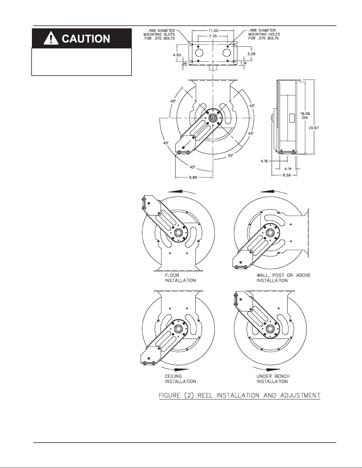
REEL INSTALLATION AND
ADJUSTMENT
See Figure (2). The guide arm may be
positioned in 45 degree increments
as shown. For ease of operation and
increased hose life, the guide arm should
be positioned to minimize hose strain as
the delivery hose is pulled through the
roller outlet.
Four studs must be used to securely
attach the guide arm.
SAFETY INFORMATION
Read and understand all warnings, cautions and instructions before operating
this equipment. Extreme caution should
be used when operating this equipment
as personal injury and/or property damage can result from equipment misuse.
Adequate personal protection is recommended to prevent splashing of material on the skin or in the eyes. ALWAYS
disconnect air coupler from pump when
the pump is not being used.
Form 404243
Page Number - 3
 Loading...