

Page 1

SERVICE MANUAL
(DOMESTIC & INTERNATIONAL)
IMPINGER CONVEYOR OVENS
LOW PROFILE - 1600 SERIES
Lincoln Foodservice Products, Inc.
1111 North Hadley Road
P.O. Box 1229
Fort Wayne, Indiana 46801-1229
Phone: (800) 374-3004 • Fax: (260) 436-0735
Technical Service Hot Line
(800) 678-9511
www.lincolnfp.com
1600SvcMan REV: 12/13/05
Page 2

TABLE OF CONTENTS
TABLE OF CONTENTS..............................................................................................................................................2
SEQUENCE OF OPERATIONS 1600 / 1601 / 1652..................................................................................................3
SEQUENCE OF OPERATIONS 1622 / 1623.............................................................................................................4
SEQUENCE OF OPERATIONS / 1628 / 1629...........................................................................................................5
SEQUENCE OF OPERATIONS / 1646, 1647, 1650, 1651........................................................................................7
SCHEMATIC / 1600, 1601, 1652 ...............................................................................................................................9
SCHEMATIC / 1622, 1623........................................................................................................................................10
SCHEMATIC / 1628, 1629........................................................................................................................................11
SCHEMATIC / 1646, 1647, 1650, 1651 ...................................................................................................................12
TROUBLESHOOTING GAS OVENS ......................................................................................................................13
TROUBLESHOOTING / 1622, 1623, 1628, 1629 ...................................................................................................20
TROUBLESHOOTING / 1646, 1647, 1650, 1651 ....................................................................................................26
REMOVAL, INSTALLATION & ADJUSTMENTS .....................................................................................................32
PARTS / GENERAL - 1600 SERIES ........................................................................................................................48
BLOW UP / GENERAL – 1600 SERIES...................................................................................................................49
PARTS / CONTROL BOX, RIGHT- 1600 - 1601 - 1652 ..........................................................................................50
BLOW UP / CONTROL BOX RIGHT – 1600, 1601, 1652 .......................................................................................51
PARTS / CONTROL BOX, LEFT - 1600 - 1601 - 1652 ............................................................................................52
BLOW UP / CONTROL BOX LEFT – 1600, 1601, 1652 ..........................................................................................53
PARTS / CONTROL BOX, RIGHT –1622,1623,1628,1629 .....................................................................................54
BLOW UP / CONTROL BOX RIGHT – 1622,1623,1628,1629 ................................................................................55
PARTS / CONTROL BOX, LEFT 1622,1623,1628,1629 .........................................................................................56
BLOW UP / CONTROL BOX LEFT – 1622, 1623, 1628, 1629................................................................................57
PARTS / CONTROL BOX RIGHT – 1646, 1647, 1650, 1651 ..................................................................................58
BLOW UP / CONTROL BOX RIGHT – 1646,1647,1650,1651 ................................................................................59
PARTS / CONTROL BOX LEFT – 1646, 1647, 1650, 1651 ....................................................................................60
BLOW UP / CONTROL BOX LEFT – 1646,1647,1650,1651...................................................................................61
PARTS / BACK - 1600 SERIES ...............................................................................................................................62
BLOW UP / BACK – 1600 SERIES ..........................................................................................................................63
PARTS / CONVEYOR - 1600 SERIES.....................................................................................................................64
BLOW UP / CONVEYOR – 1600 SERIES ...............................................................................................................65
Low Profile -–1600 Series Service Manual – Dom & Int’l2
Page 3

SEQUENCE OF OPERATIONS 1600 / 1601 / 1652
MODEL 1600 / 120 VAC / 60 HZ / NATURAL GAS
MODEL 1601 / 120 VAC / 60 HZ /L.P. GAS
MODEL 1652 / 120 VAC / 60 HZ / TOWN GAS
POWER SUPPLY Electrical power to be supplied to the oven by a three conductor cordset. Voltage from
the black conductor to the white conductor is 120 VAC.
White conductor is Neutral.
Green conductor is Ground.
CONTROL BOX
AUTO COOL DOWN
MAIN FAN CIRCUIT 120 VAC is permanently supplied to the normally open contacts of the Oven Power
BURNER CIRCUIT Closing the Oven Power Relay energizes the coil of the Burner Relay. The (2)
TEMPERATURE
CONTROL
CONVEYOR DRIVE Closing the Power Switch supplies 120 VAC, through the contact of the Oven Power
TIME/TEMP DISPLAY
When the temperature in either one of the Control Boxes reaches 120°F ± 3°F (49°C
± 1.7°C), the Cooling Fan Thermostats will switch power to the Cooling Fans. The
thermostats will interrupt power to the Cooling Fans when the temperature falls to
100°F ± 3°F (37°C ± 1.7°C).
Relay, to terminal #1 of the 20-Minute Time Delay Module, the normally open
contacts of the Fan Relay and to the (2) normally open Cooling Fan Thermostats.
Closing the normally open Power Switch supplies 120 VAC to the coil of the Oven
Power Relay. These normally open contacts now close, enabling the 20-Minute Time
Delay Module. The 20 Minute Time Delay Module supplies 120 VAC to the Oven Fan
Relay, these normally open contacts now close, supplying 120 VAC, through a 10
Amp fuse, to the (2) Main Fan Motors and, through a 3 Amp fuse, to the (2) Control
Box Cooling Fans.
normally open contacts now close supplying120 VAC to the (2) burner systems.
NOTE: This oven utilizes (2) complete Burner/Temp. Control Systems. The sequence
of operations is the same for each system.120 VAC is supplied, through the
Centrifugal Switch of the Main Fan Motor (this switch closes when the Main Fan
reaches approximately 1600 R.P.M.) through the 10 Amp Fuse, to the Ignition
Control, the Electronic Temperature Control, and to the Burner Blower Motor. As this
Blower reaches approximately 1600 R.P.M., its internal centrifugal switch will close,
supplying 120 VAC through the cooling fan sail switch to the Burner Transformer.
NOTE: The Cooling Fan Sail Switch is mounted in front of the cooling fan and is
activated by the air flow of the Cooling Fan. The secondary of the Transformer
supplies 24 VAC to the Ignition Control. The Ignition Control operates on both 24 VAC
and 120 VAC. When the control is energized by 24 VAC, 120 VAC is switched to the
Hot Surface Ignitor for 45 seconds for Hot Surface Igniter warm up 24 VAC is now
switched to the Gas Valves which open. Ignitor glows red, and ignition should now
occur. The red Indicator Light is also now energized. If ignition does not occur within 6
seconds, the control will lock out. To retry after lockout, turn off the burner switch, wait
45 seconds, and then turn the switch back on.
When the Centrifugal Switch of the Burner Blower Motor closes, power is applied to
the Temperature Control. The2.5 K ohm Temperature Pot is adjusted to desired
temperature. The thermocouple will provide varying millivolts to theTemperature
Controller. The Temperature Controller supplies 120 VAC to Temperature Regulation
Valve at intermittent intervals to maintain desired temperature.
Relay, to the primary of the (2) Time/Temp. Transformers. The secondary output of
the Transformers, 12.5 to 15 VAC with a center tap, is supplied to terminals 1, 2, and
3 of the Time/Temp. Display. The Display works on a balanced input, and center tap
voltage to each leg must be 1/2 the total reading.
The speed side of the Time/Temp. Display is supplied, by the Conveyor Control, with
the frequency of the pulses to the Conveyor Motor. This frequency is converted by the
Time/ Temp. Display into a read out of minutes and seconds.
The Conveyor Control uses a sensor and magnet, mounted on the Conveyor Motor,
NOTE
Low Profile -–1600 Series Service Manual – Dom & Int’l 3
that senses when the motor is turning. If the motor is not turning, the Time/Temp.
Display will show "--:--" in the window.
The temperature portion of the display uses a Thermistor Probe to sense oven
temperature. The Thermistor outputs a resistance proportional to oven temperature.
This resistance is then converted by the Display into a temperature reading.
Page 4

OR:
The temperature portion of the display uses a "J" type thermocouple to measure oven
temperature. The thermocouple generates D.C. millivolts proportional to oven
temperature. This millivolt reading is then converted by the display into a temperature
reading.
The oven utilizes (2) Temperature Display systems, one each for the left and right
sides of the cooking chamber.
SEQUENCE OF OPERATIONS 1622 / 1623
MODEL 1622 / 120/208 VAC./.3 PHASE 60 HZMODEL
1623 / 120/240 VAC / 3 PHASE. / 60 H
POWER SUPPLY Electrical power to be supplied to the oven by a five conductor service.
Voltage from the black conductor to the white conductor is 120 VAC.
Black conductor is Hot.
Red conductor is Hot.
Orange conductor is Hot.
White conductor is Dedicated Neutral.
Green conductor is Ground.
CONTROL BOX
AUTO COOL DOWN
MAIN FAN CIRCUIT Electrical power is permanently supplied through (6)- 50 A. fuses to the normally
When the temperature in either one of the Control Boxes reach 120°F± 3°F (49°C±
1.7°C), the Cooling Fan Thermostats will switch power to the Cooling Fans. The
thermostats will interrupt power to the Cooling Fans when the temperature
falls to 100°F± 3°F (37°C ± 1.7°C).
open contacts of the mercury contactors. Power is also supplied, through a 10A fuse,
to the Oven Power Switch , through a 3A fuse to a normally open contact of the
Oven Fan Relay, term. # 1 of the 20 minute Time Delay Module and the (2)
normally open Cooling Fan Thermostats. Power is also supplied to a normally open
contact of the the Oven Power Relay. Closing the normally open Oven Power
Switch supplies 120 VAC to the coil of the Oven Power Relay. These normally open
contacts now close, enabling the 20 minute Time Delay Module. The 20 minute
Time Delay Module supplies 120 VAC to the coil of the oven fan relay, these
normally open contacts now close, supplying 120 VAC to the (2) Main Fans and
to the (2) Control Box Cooling Fans.
HEAT CIRCUIT Closing the Oven Power Relay, supplies 120 VAC, through a 3 A fuse, to the (2)
heat systems.
NOTE: This oven utilizes (2) complete Heat/Temp control systems. The sequence of
operations is the same for each system.120 VAC is supplied, through the
Centrifugal Switch of the Main Fan Motor, (This switch closes when the Main Fan
reaches approximately 1600 R.P.M.) through the normally closed High Limit
Thermostat (manually re-settable which opens at 660° F, 350°C) through the
normally open Cooling Fan Sail Switch to the Electronic Temperature Control and
the Heat Indicator Light.
NOTE: The Cooling Fan Sail Switch is mounted in front of the Cooling Fan and is
activated by the air flow of the Cooling Fan.
TEMPERATURE
CONTROL
CONVEYOR DRIVE Closing the Oven Power Switch supplies 120 VAC, through the contact of the Oven
When the Cooling Fan Sail Switch closes, 120 VAC is supplied to the Temperature
Control. The Temperature Control Potentiometer (2.5K ohm) is adjusted to desired
temperature. The Thermocouple will provide varying millivolts to the Temperature
Controller. TheTemperature Controller supplies 120 VAC to the contactor coil at
intermittent intervals, (closing the Contactor and supplying 208 or 240 VAC to the
Heating Elements) to maintain desired temperature.
Power Relay, to the normally open Conveyor Switch. Closing the Conveyor Switch
supplies 120 VAC, through a 3 Amp Fuse, to the primary of the Conveyor Control
Transformer. The secondary of this Transformer supplies 10 VAC and 29 VAC to the
Low Profile -–1600 Series Service Manual – Dom & Int’l4
Page 5

TIME/TEMP DISPLAY
Line voltage is permanently supplied through (6) 50 A. fuses, to the normally open mercury
to a normally open contact of the Oven Fan Relay, through a 3A fuse to the primary of the control
(The transformer steps the voltage down to 120 VAC for the control circuit). 120 VAC is permanently
supplied to a normally open contact of the Oven Fan Relay, the (2) normally open cooling fan
terminal #1 of the 20 minute Time Delay Module and to the normally open Power Switch. Closing the
NOTE: The Conveyor Control uses a Sensor and Magnet, mounted on the Conveyor Motor,
Conveyor Control. The Conveyor Control supplies voltage pulses to the Conveyor
Motor. The ConveyorControl Potentiometer varies the frequency of these pulses.
The motor speed will increase or decrease, as the frequency of the pulses increase
or decrease respectively.
Closing the Oven Power Switch supplies 120 VAC, through the contact of the Oven
Power Relay, to the primary of the (2) Time/TempTransformers. The secondary
output of the Transformers, 12.5 to 15 VAC with a center tap, is supplied to
terminals 1, 2, and 3 of the Time/Temp. Display. The display works on a balanced
input, and center tap voltage to each leg must be 1/2 the total reading. The speed
side of the Time/Temp. Display is supplied, by the Conveyor Control, with the
frequency of the pulses to the Conveyor Motor. This frequency is converted by the
Time/Temp. Display into a read out of minutes and seconds.
that senses when the motor is turning. If the motor is not turning, the Time/Temp.
Display will show "- - : --" in the window.
The temperature portion of the display uses a Thermistor Probe to sense oven
temperature. The Thermistor outputs a resistance proportional to oven temperature.
This resistance is then converted by the Display into a temperature reading.
OR:
The temperature portion of the display uses a "J" type thermocouple to measure
oven temperature. The thermocouple generates D.C. millivolts proportional to oven
temperature. This millivolt reading is then converted by the display into a
temperature reading. The oven utilizes (2) Temperature Display systems, one each
for the left and right sides of the cooking chamber.
SEQUENCE OF OPERATIONS / 1628 / 1629
POWER SUPPLY
CONTROL BOX
AUTO COOL DOWN
MAIN FAN CIRCUIT
MODEL 1628 / 380/220 VAC / 3 PHASE / 50 HZ
MODEL 1629 / 415/240 VAC / 3 PHASE / 50 HZ
Electrical power to be supplied to the oven by a five conductor service.
Brown conductor is hot.
Black conductor is hot.
Black conductor is hot.
Blue conductor is neutral.
Green/yellow conductor is ground.
When the temperature in either one of the Control Boxes reaches 120°F ± 3°F (49°C
± 1.7°C), the Cooling Fan Thermostats will
switch power to the Cooling Fans. The thermostats will interrupt power to the Cooling
Fans when the temperature falls to 100°F ±
3°F (37°C ± 1.7°C).
contactors, through a 10A fuse,
circuit step down transformer.
thermostats, a normally open contact of the Oven Power Relay,
Power Switch supplies
120 VAC to the Oven Power Relay, its contacts now close, enabling the 20 minute
Time Delay Module. The 20 -minute Time Delay Module supplies 120 VAC to the
Oven Fan Relay, its contacts now close. supplying line voltage to the (2) Main Fan
Motors and 120 VAC to the (2) cooling fans. 120 VAC is also supplied to the (2)
Time/Temp Transformers, the (2) electronic temperature controls and to the normally
Low Profile -–1600 Series Service Manual – Dom & Int’l 5
Page 6

open Conveyor Switch.
Closing the Oven Power Relay supplies 120 VAC, through a 3A fuse, to the (2) Heat/Temperature
NOTE: This oven utilizes (2) complete Heat/Temperature Control systems. The sequence of
120 VAC is supplied through a normally open Air Pressure Switch, (closed by air pressure from the
closed Hi-limit Thermostat, (manually re-settable opens at 350°C (662°F)) through the Cooling Fan
HEAT CIRCUIT
Control systems
operations is the same for both systems,
Main Fan),through the normally
Sail Switch to the Electronic
Temperature Control Board.
NOTE: The Cooling Fan Sail Switch is mounted in front of the Cooling Fan and is
activated by the air flow of the Cooling Fan
TEMPERATURE
CONTROL
When the Sail Switch closes, power is applied to the Electronic Temperature Control.
The 2.5 K Ohm Temperature Pot. is
adjusted to the desired temperature. The Thermocouple will provide varying millivolts
to the Temperature Controller. The Temperature Controller supplies 120 VAC to the
contactor coil at intermittent intervals (closing the contactor and supplying 220 or 240
VAC to
the heating elements) to maintain desired temperature
CONVEYOR DRIVE Closing the Oven Power Switch supplies 120 VAC, through the contact of the Oven
Power Relay, to the normally open Conveyor Switch. Closing the Conveyor Switch
supplies 120 VAC, through a 3 Amp Fuse, to the primary of the Conveyor Control
Transformer. The secondary of this Transformer supplies 10 VAC and 29 VAC to the
Conveyor Control. The conveyor control supplies voltage pulses to the Conveyor
Motor. The Conveyor Control Potentiometer varies the frequency of these pulses. The
motor speed will increase or decrease, as the frequency of the pulses increase or
decrease respectively.
TIME/TEMP DISPLAY Closing the Oven Power Switch supplies 120 VAC to the primaries of the (2)
Time/Temp. Transformers. The secondary output of the Transformers, 12.5 to 15
VAC with a center tap, is supplied to terminals 1, 2, and 3 of the Time/Temp. Display.
The Display works on a balanced input, and center tap voltage to each leg must be
1/2 the total reading. The speed side of the Time/Temp. Display is supplied, by the
Conveyor Control, with the frequency of the pulses to the Conveyor Motor. These
pulses are converted by the Time/Temp. Display into a read out of minutes and
seconds.
NOTE: The Conveyor Control uses a sensor and magnet, mounted on the Conveyor Motor,
that senses when the motor is turning. If
the motor is not turning, the Time/Temp. Display will show"--:--" in the window.
The temperature portion of the display uses a Thermistor Probe to sense oven
temperature. The Thermistor outputs a resistance proportional to oven temperature.
This resistance is then converted by the Display into a temperature reading.
OR:
The temperature portion of the display uses a "J" type thermocouple to measure oven
temperature. The thermocouple generates D.C. millivolts proportional to oven
temperature. This millivolt reading is then converted by the display into a temperature
reading.
The oven utilizes (2) Temperature Display systems, one each for the left and right
sides of the cooking chamber.
Low Profile -–1600 Series Service Manual – Dom & Int’l6
Page 7

SEQUENCE OF OPERATIONS / 1646, 1647, 1650, 1651
CONTROL BOX AUTO COOL AUTO
MODEL 1646 / 220-240 VAC / 50 HZ / NATURAL GAS
MODEL 1647 / 220-240 VAC / 50 HZ / L.P. GAS
MODEL 1650 / 220-240 VAC / 50 HZ / TOWN GAS
MODEL 1651 / 220-240 VAC / 50 HZ / TOWN GAS
POWER SUPPLY Electrical power to be supplied to the oven by a three conductor service.
Brown conductor is hot.
Blue conductor is neutral.
Green conductor is ground.
When the temperature in either one of the Control Boxes reaches 120°F ± 3°F (49°C
± 1.7°C), the Cooling Fan Thermostats will switch power to the Cooling Fans. The
COOL DOWN
MAIN FAN CIRCUIT Line voltage is permanently supplied to a normally open contact of the oven power
BURNER CIRCUIT NOTE: This oven utilizes (2) complete Burner/Temp. Control Systems. The sequence
TEMPERATURE
CONTROL
CONVEYOR DRIVE Closing the Oven Power Switch supplies 120 VAC, through the contact of the Oven
TIME/TEMP DISPLAY Closing the Oven Power Switch supplies 120 VAC, through the contact of the Oven
NOTE:
thermostats will interrupt power to the Cooling Fans when the temperature falls to
100°F ± 3°F (37°C ± 1.7°C).
switch, through a 10A fuse to the normally open oven fan relay, and through a 3A
fuse to the primary of the control circuit step down transformer (The transformer steps
the voltage down to 120 VAC for the control circuit). 120 VAC is permanently supplied
to the (2) normally open cooling fan thermostats, a normally open contact of the cool
down relay, terminal #1 of the 20 -minute time delay module and to the normally open
oven power switch. Closing the oven power switch supplies 120 VAC to the cooldown relay, its contacts now close, supplying 120 VAC to the (2) cooling fans. and
enabling the 20 minute time delay module. The 20-minute time delay module supplies
120 VAC to the oven fan relay, its contact now closes supplying line voltage to the (2)
main fan motors. 120 VAC is also supplied to the (2) time/temp transformers, the
conveyor switch and the (2) electronic temperature controls.
of operations is the same for each system. Closing the normally open oven power
switch supplies line voltage through a 3A fuse, through the sail switch, through the
gas pressure switch, through the Main Fan Air Pressure Switch, through the Hi-limit
Thermostat, to the Ignition Control. The combustion motor is energized. The normally
open combustion air switch closes upon sensing air pressure. After a pre-purge
period of between 30 and 60 seconds, the Ignition Transformer and the Main Gas
Valve are energized. Ignition should now occur.
NOTE: The Cooling Fan Sail Switch is mounted in front of the cooling fan and is
activated by the air flow of the Cooling Fan.
Closing the Oven Power Switch supplies 120 VAC (through the Step Down
Transformer) to the Temperature Control Board. The 2.5k ohm Temperature Pot is
adjusted to desired temperature. The Thermocouple will provide varying millivolts to
the Temperature Controller. The Temperature Controller supplies 120 VAC to the
Solenoid Valve at intermittent intervals to maintain desired temperature.
Power Relay, to the normally open Conveyor Switch. Closing the Conveyor Switch
supplies 120 VAC, through a 3 Amp Fuse, to the primary of the Conveyor Control
Transformer. The secondary of this Transformer supplies 10 VAC and 29 VAC to the
Conveyor Control. The conveyor control supplies voltage pulses to the Conveyor
Motor. The Conveyor Control Potentiometer varies the frequency of these pulses. The
motor speed will increase or decrease, as the frequency of the pulses increase or
decrease respectively.
Power Relay, to the primary of the (2)Time/Temp. Transformers. The secondary
output of the Transformers, 12.5 to 15 VAC with a center tap, is supplied to terminals
1, 2, and 3 of the Time/Temp. Display. The Display works on a balanced input, and
center tap voltage to each leg must be 1/2 the total reading. The speed side of the
Time/Temp. Display is supplied, by the Conveyor Control, with the frequency of the
pulses to the Conveyor Motor. These pulses are converted by the Time/Temp.
Display into a read out of minutes and seconds.
The Conveyor Control uses a sensor and magnet, mounted on the Conveyor Motor,
that senses when the motor is turning. If the motor is not turning, the Time/Temp.
Display will show "--:--" in the window. The temperature portion of the display uses a
Low Profile -–1600 Series Service Manual – Dom & Int’l 7
Page 8

Thermistor Probe to sense oven temperature. The Thermistor outputs a resistance
proportional to oven temperature. This resistance is then converted by the Display
into a temperature reading.
OR:
The temperature portion of the display uses a "J" type thermocouple to measure oven
temperature. The thermocouple generates D.C. millivolts proportional to oven
temperature. This millivolt reading is then converted by the display into a temperature
reading.
The oven utilizes (2) Temperature Display systems, one each for the left and right
sides of the cooking chamber.
Low Profile -–1600 Series Service Manual – Dom & Int’l8
Page 9
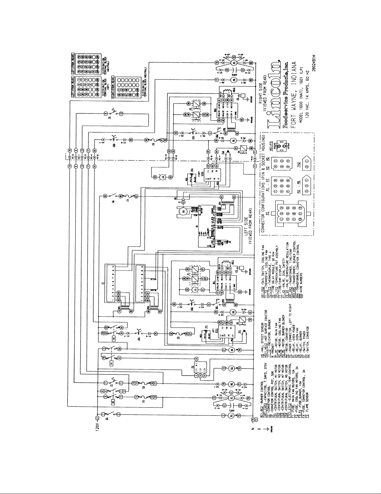
SCHEMATIC / 1600, 1601, 1652
Low Profile -–1600 Series Service Manual – Dom & Int’l 9
Page 10
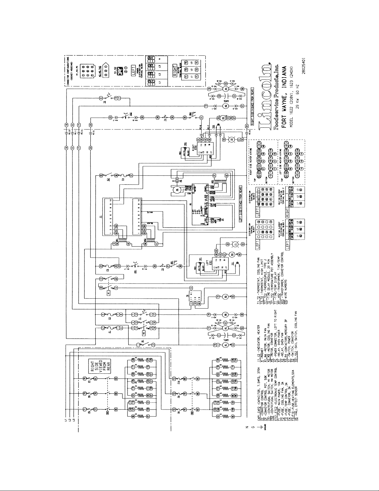
SCHEMATIC / 1622, 1623
Low Profile -–1600 Series Service Manual – Dom & Int’l10
Page 11
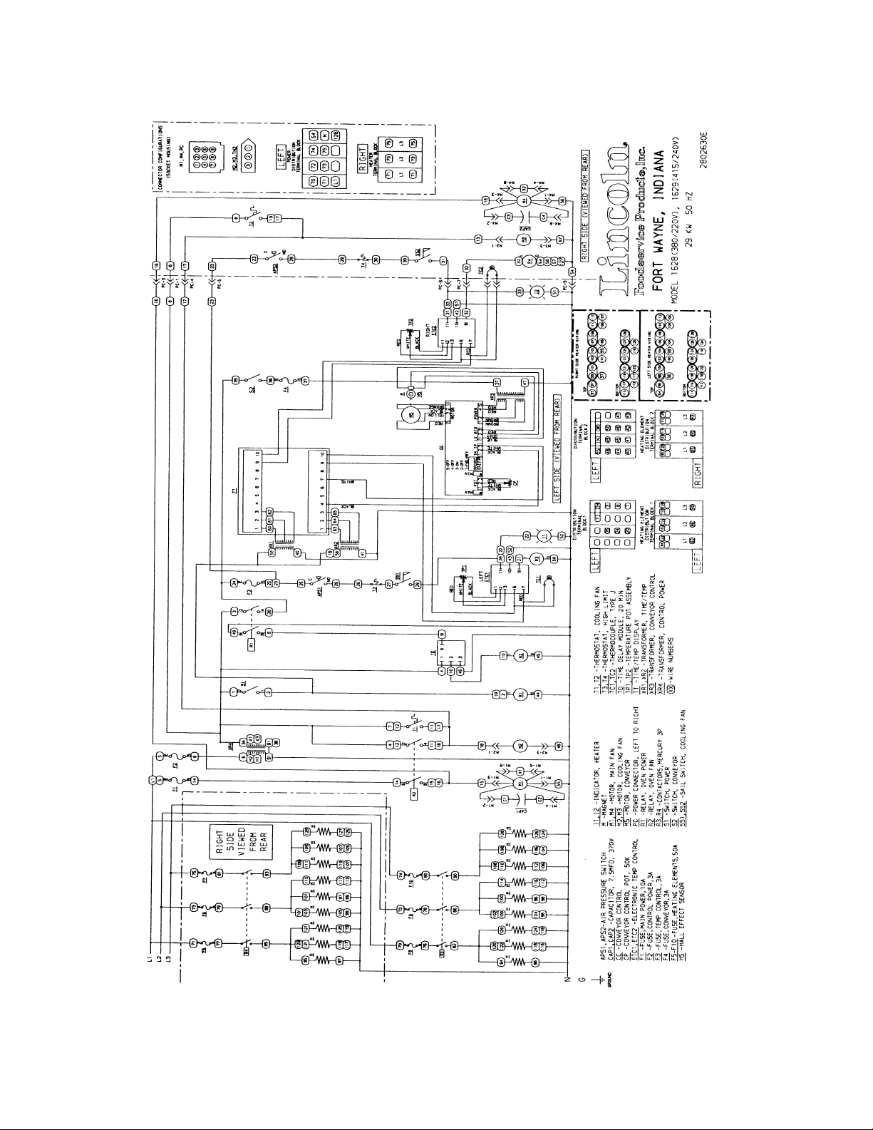
SCHEMATIC / 1628, 1629
Low Profile -–1600 Series Service Manual – Dom & Int’l 11
Page 12
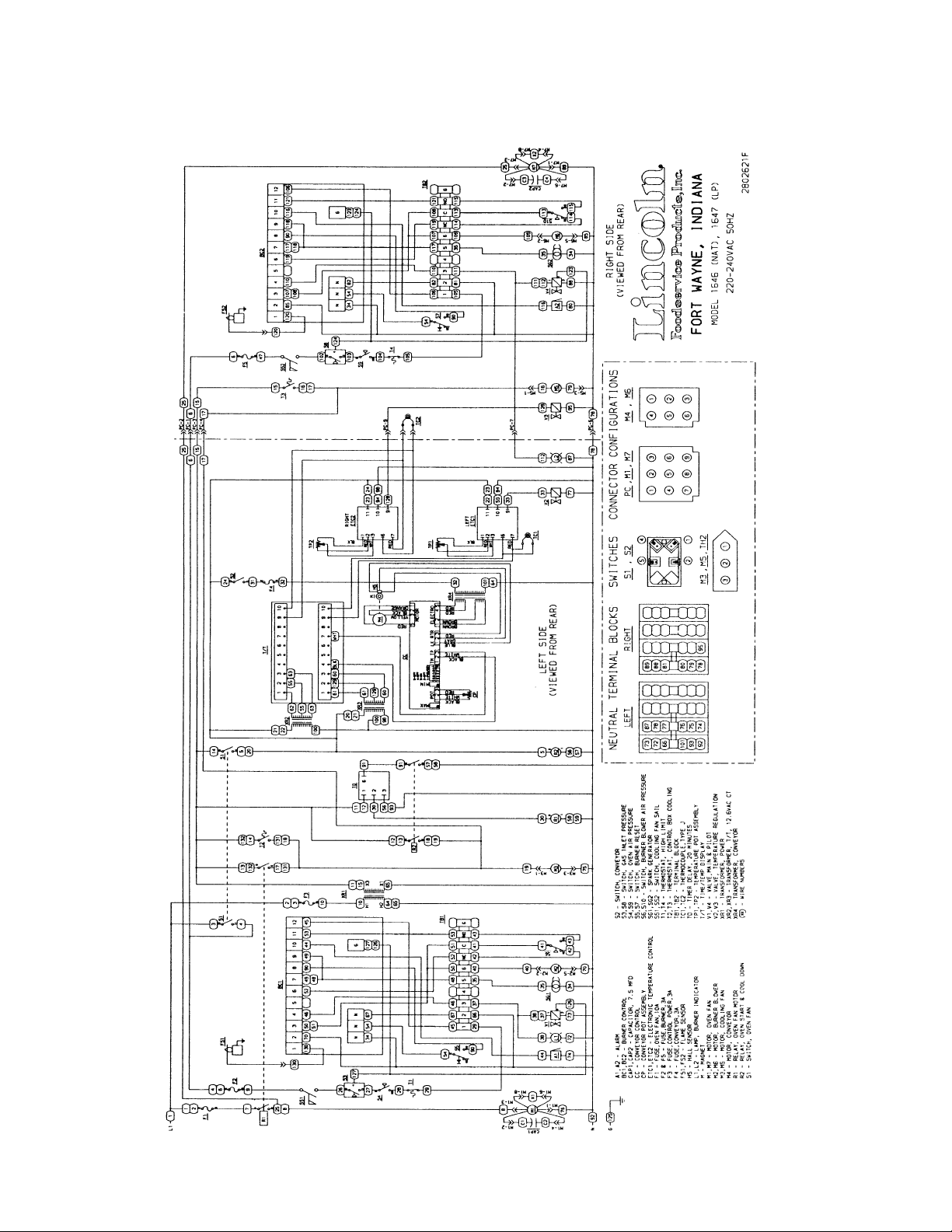
SCHEMATIC / 1646, 1647, 1650, 1651
Low Profile -–1600 Series Service Manual – Dom & Int’l12
Page 13
TROUBLESHOOTING GAS OVENS
MODEL 1600, 1601, 1652
1600-000-DB, 1601-000-DB
NOTE: When checking components on left side of unit, be sure to check wire harness across back of
oven for proper connections in power connector, (marked P. C. on Schematic Diagram, inside control
box cover).
SYMPTOM POSSIBLE CAUSE EVALUATION
Oven fan(s) will not run
No main fan cool down
Main fan runs after20
minute cool down
No control box cooling
Incoming Power Supply Check breakers/Reset if required/ Call Power
Company if needed.
Power Switch Check continuity between switch terminals.
Oven Power Relay Check for 120 VAC to the relay coil. If voltage is not
present, trace wiring back to the fan switch. If voltage
is present, check to insure contacts are closing.
Check for 120 VAC supplied t terminal #2 of the relay.
20 Minute Time Delay Check for 120 VAC at terminal #1 to neutral on the 20
minute timer. If no voltage is present, trace wiring
back to the power supply. If voltage is present at
terminal #1, check for 120 VAC at terminal #2 to
neutral. If no voltage is present, and the oven power
relay is closed, replace the 20 minute timer.
Oven Fan Relay Check for 120 VAC to coil of the oven fan relay. If no
voltage is present, trace wiring back to terminal #2 of
the 20minute timer. Check for 120 VAC at terminals
#2 and #6 of the relay, if no voltage is present, trace
wiring back to the power supply. If voltage is present
at the relay coil, check to insure the contacts are
closing.
Fuse, Fan, 10A Check, replace if necessary.
Fuseholder Check, replace if necessary
Capacitor(s) Check for opens, shorts, or grounds.
Motor(s)
20 Minute Time Delay Check for 120 VAC at terminal #2 to neutral while
Oven Fan Relay Check if relay is operating and that the contacts
Oven Power Relay Contacts should open when main fan switch is turned
20 Minute Time Delay 120 VAC at terminal #2 should discontinue
Oven Fan Relay Check to insure that the contacts are opening after the
Power Switch
Oven Power Relay
20 Minute Time Delay
Oven Fan Relay
Fuse, Cooling Fans (3A) Check, replace if necessary.
Fuseholder Check, replace if necessary
Cooling Fan(s) 120 VAC should now be at these motors. If voltage is
Check for opens, shorts, or grounds. WITH POWER OFF:
turn the fan blade(s) to check for locked rotor.
oven is "on". Turn off the main fan switch, 120 VAC
should continue to be present for 20 minutes. If
voltage is not present for approx. 20 minutes, replace
the timer.
remain closed during the 20 minute cool down.
off.
approximately 20 minutes after main fan is switched
off. If the oven power relay contacts are open, and the
voltage continues at terminal #2 of the 20 minute
timer, for more than 20 mins., replace the timer.
coil is de-energized.
(SEE MAIN FAN WILL NOT RUN)
present, check motor(s) for shorts, opens, or grounds
WITH POWER OFF: check for locked rotor.
Low Profile -–1600 Series Service Manual – Dom & Int’l 13
Page 14
No automatic control
Centrifugal Switch of Main Fan Motor
Check for 120 VAC supply to the burner blower motor, if 120 VAC is
box cooling
Incoming Power Supply Check circuit breakers, reset if required. Call the
Power Company if needed.
Cooling Fan Thermostat(s) Check the cooling fan thermostat. (Thermostat closes
at 120°F and opens at 100°F.) With the cooling fan
thermostat pre-heated, check for continuity. If switch
is open, replace.
Fuse, Cooling Fans (3A)
Fuseholder
Cooling Fan(s)
Check, replace if necessary.
Check, replace if necessary.
120 VAC should now be at these motors. If voltage is
present, check motor(s) for shorts, opens, or grounds.
WITH POWER OFF: check for locked rotor .
Cooling fans continue
to run after 20 minute
cool down
Cooling Fan Thermostat(s) Thermostat is normally open and may have closed if
control box temperature is 120°F or above.
Oven Fan Relay Check to insure contacts are opening after the 20
minute cool down.
Oven will not heat
Gas Supply Check for adequate gas supply and closed manual
gas shut-off.
Main Fan(s) If not operating, refer to "Oven fan will not run." Page
13 “
Burner relay 120 VAC should be present at the coil of burner relay.
If voltage is not present, trace wiring back to the oven
power relay and back to power supply if needed. If
voltage is present, check to insure the relay contacts
are closing. Replace as necessary
.
NOTE: These ovens utilize 2 complete Burner/Temperature control systems. Each system will
follow the same Troubleshooting Sequence.
Check for 120 VAC supplied to the centrifugal switch, if
voltage is not present, trace the wiring back to the
burner relay. Check for 120 VAC out of the centrifugal
switch. If voltage is supplied to the centrifugal switch,
and motor is running, but there is no voltage out of the
centrifugal switch, replace the fan motor.
(NOTE: see Schematic Diagram for proper wire
numbers on motors)
Fuse, Burner 10A Check, replace if necessary.
Fuseholder Check, replace if necessary.
Burner Blower Motor
present and motor does not run, replace the motor.
WITH POWER OFF: turn blower wheel to check for
locked rotor.
Centrifugal Switch of Burner
Blower Motor
Check for 120 VAC supply to the centrifugal switch of
burner blower motor (see Schematic for proper wire
numbers). If no voltage is present, trace wiring back to
the fuseholder. If voltage is present, check for 120 VAC
at the output of the centrifugal switch. If there is no
output, and the burner blower motor is running, replace
the burner blower motor.
Low Profile -–1600 Series Service Manual – Dom & Int’l14
Page 15

Control Box Cooling Fan Check to insure the control box cooling fan is operating
properly. If the cooling fan is not operating, refer to "No
control box cooling" Page 14”.
Cooling Fan Sail Switch (NOTE: the cooling fan sail switch is located in front of
the cooling fan and is activated by the air flow from the
cooling fan.) Check for 120 VAC supply to the sail
switch (see Schematic for proper wire numbers).
Visually check to see the sail switch is closing as
cooling fan is running, if the sail switch is not closing,
check for obstructions or damage to the sail switch. If
the sail switch is closing, check for 120 VAC out of the
sail switch. If there is no voltage, and the sail switch is
closed, replace the sail switch.
Burner Transformer Check for 120 VAC to primary of the 24 VAC burner
transformer. If voltage is not present, trace wiring back
to the sail switch. If voltage is present, check for 24
VAC at the secondary, if no secondary voltage is
present, replace the transformer.
Ignition Control Check for 24 VAC supply to the ignition control at
terminals marked 24V and 24Vgnd. If voltage is not
present, trace wiring back to the 24 VAC transformer.
Check for 120 VAC supply to the ignition control at
terminals L1 and L2. If no voltage is present, trace
wiring back to terminal #11 on the temperature control.
If the above checks are okay, proceed. The ignition
control should switch 120 VAC to the hot surface
igniter, across the (2) terminals marked HSI. If no
voltage is present, replace ignition control.
Hot Surface Igniter(located
inside Burner Assy.)
Ignition Control After 45 seconds of hot surface igniter pre-heat, the
Gas Control Valves Check for 24 VAC supplied to the gas control valves. If
If 120 VAC is present at HSI terminals, visually check
to see that the hot surface igniter is heating (igniter
may be viewed through port glass in end of burner
tube). The igniter should glow bright red. Check all
connections to be sure they are tight. If the igniter does
not heat, replace.
ignition control will switch 24 VAC to the gas control
valves. Check for 24 VAC output from the ignition
control, and across terminals marked "valve" and
"valve gnd". If no voltage is present, replace the ignition
control. NOTE: the ignition control contains a safety
lock-out circuit. If a flame is not detected within 6
seconds after the gas control valve is energized, the
ignition control will lock-out. To reset, turn the burner
switch "off", wait 45 seconds and switch the burner
system "on" to retry ignition
voltage is present, the valves should open. Check for
gas pressure at the pressure tap, located in the gas
piping just prior to the burner. If there is no gas
pressure, and the voltage is supplied to valves, check
piping for obstructions. If there are no obstructions,
replace gas control valves. NOTE: the red burner
indicator light is wired in parallel with the gas control
valves. When 24 VAC is supplied to the gas control
valves the red burner indicator light is also energized.
Low Profile -–1600 Series Service Manual – Dom & Int’l 15
Page 16

Flame will not stay lit
Low flame is on, but
no main flame.
Hot Surface Igniter The ignition control will keep the gas control valves
energized for 6 seconds. At the end of 6 seconds, the
hot surface igniter must sense a flame, or, the ignition
control will go into lock- out. (The ignition control
requires a minimum of 0.8 microamps D.C.) To check
the flame sensing operation, connect a digital
multimeter (capable of measuring D.C. micro-amps)
between the "ground" terminal on ignition control and
the ground lead.
NOTE: This is a current measurement and the meter
must be connected in series. If these readings are not
achieved, check bypass orifice for obstructions, if
bypass orifice is clear, replace the hot surface igniter.
NOTE: The D.C. micro amp test must be conducted
with the oven in low flame (bypass) operation. Turn the
temperature control to its lowest setting
Power Supply If there is sufficient micro-amp current, but the flame
will not stay lit, check for proper polarity of the 120 VAC
power supply
Ignition Control If there is sufficient micro-amp current, and the 120
VAC polarity is correct, but the flame will not stay lit,
replace the ignition control.
NOTE: Check for proper ground connection of the
ignition control.
NOTE: Flame should be
present at this time
Thermocouple Probe WITH POWER ON AND THERMOCOUPLE LEADS
Temperature Control
Potentiometer
Check for 120 VAC supply at terminal #11 to neutral on
the temperature control. If no voltage is present, trace
the wiring back to 10 A fuse. Turn the temperature
adjustment knob to its maximum temperature position
and check for 120 VAC at the load terminal (#9) and
neutral. If 120 VAC is present and unit is not heating,
refer to "Temperature Regulation Valve" for next check.
If 120 VAC is not present, proceed.
ATTACHED TO THE TEMPERATURE CONTROL
BOARD: measure the D. C. millivolt output of these
leads. Refer to the thermocouple chart page 43 for
proper readings. If these readings are not achieved,
replace the thermocouple.
WITH POWER OFF: remove the potentiometer leads
from the temperature control board and measure ohms
from black to white leads. The reading should be from
0 to 2.5k ohms ± 10% as the dial of the potentiometer
is turned throughout its full rotation. From black to red
leads, the reading should be 2.5k ohms ± 10%
(constant) throughout the full rotation of the dial. If
these readings are not achieved, replace the
potentiometer. If the thermocouple probe and the
control potentiometer check good, then the problem is
usually with the temperature control board.
Temperature Regulation
Valve
If 120 VAC is present on the temperature control board
at load terminal (#9) to neutral, check for voltage at the
temperature regulation valve. If voltage is present,
listen for the valve to open and close. Also check for
opens or shorts inthe coil. Replace as necessary.
Low Profile -–1600 Series Service Manual – Dom & Int’l16
Page 17
Intermittent Heating Thermal/Overload The main fan motors, burner blower motors, and
cooling fan motors are equipped with internal thermal
protection and will cease to operate if overheating
occurs. As the motors overheat and then cool, this will
cause the units to cycle on and off intermittently.
Improper ventilation or preventive maintenance may
cause this. Also, most of the problems listed under
"Oven will not heat" on Page 14 can cause intermittent
failure.
NOTE: The 1600-000-DB series ovens utilize 2 complete conveyor drive systems.
Conveyor will not run
Conveyor Switch Check for 120 VAC to conveyor switch. If no voltage
is present, trace wiring back to the oven fan switch.
WITH POWER OFF: Check continuity between
switch terminals.
Conveyor Fuse (3A) Check, replace if necessary.
Fuseholder Check, replace if necessary.
Conveyor Control
(Stepper) Transformer
Speed Adjustment
Potentiometer
Conveyor Motor
(Stepper) Control
Conveyor Drive(Stepper)
Motor
Check for 120 VAC supply to primary of transformer,
if voltage is not present, trace wiring back to the
fuseholder. If voltage is present check for output
voltage from the transformer secondary
NOTE: this control transformer outputs (2) secondary
voltages
Red Leads 29 VAC
Brown Leads 10 VAC
If BOTH secondary voltages are not present, replace
the transformer.
This is a 0 to 50k ohm, 10 turn Brown Leads 10 VAC
potentiometer.
WITH POWER OFF: remove the 3 pin potentiometer
cable plug from the motor control board. With a
digital multimeter, check the ohm reading across the
red lead to the black lead, this reading should be 50k
ohms ± 5% as the potentiometer is rotated through
its 10 turn rotation. Place the meter leads on the red
lead and white lead. Rotating the potentiometer
slowly, from low to high, the meter should show an
even transition from 0 to 50k ohms ± 5% through the
10 turn rotation of the potentiometer. There should
be no dead or open spots through the 10 turns of the
potentiometer. Check all three leads to ground.
There should be no continuity to ground. If any of the
above checks fail, replace the potentiometer.
NOTE: if the conveyor drive motor becomes jammed
or begins to run at an uncontrolled speed, the
conveyor motor will stop running. To reset, turn off
the conveyor switch, wait 30 seconds, turn the
conveyor switch on. If the motor does not run after
attempting re-set, check for 2 to 29 VAC across the
motor terminals 1 to 2 and 3 to 5 on the conveyor
motor control. If voltage is not present at both sets of
terminals, replace control.
Check the drive sprocket on motor output shaft to
insure that it is tight. Check motor windings;
measurements should be approximately 2 ohms.
Terminal 1-5, 2-6, 3-7, 4-8.
WITH POWER OFF: Turn the motor shaft to check
for jammed gear box. If motor shaft will not turn,
replace conveyor drive (stepper) motor.
Low Profile -–1600 Series Service Manual – Dom & Int’l 17
Page 18

Time/Temp. Display
inoperative
NOTE: these units utilize
(2) complete temperature
display systems containing
like components.
Temp. display out or
erratic
Temp. display
inaccurate, erratic,
or inoperative
12 VAC Power
Supply(Transformer)
Time/Temp. Display If proper voltage is present at terminals 1, 2, and 3
NOTE: Time/Temp
displays uses two types
of temperature sensor,
Thermistor Probe2 yellow
wires, Thermo- couple
Probe 1 red wire and 1
white wire
Thermistor Probe Disconnect the yellow tipped thermistor leads from
Thermocouple Probe Measure D.C. millivolts at terminals 9 and 10 on the
Power Supply If a strange or unusual behavior is experienced, such
Time/Temp. Display Perform the power supply check, the thermistor
Measure the transformer primary for a nominal 120
VAC input, if voltage is not present, trace wiring back
to the power supply. Measure the secondary output,
which will normally be 12-15 VAC. Voltage across
terminals 1 and 3 on the time/temp. display should
read 12-15 VAC. Terminals 1-2 and 2-3 should be
1/2 the voltage reading 1 to 3. If the above secondary
readings are not achieved, replace transformer.
on time/temp. display, but the display is not lighted,
recheck all connections for tightness. If time/temp.
display is still not operating, replace the time/temp.
display
Connect the thermocouple of a pyrometer to the
thermocouple on the temperature control board. (Be
sure to maintain proper polarity of thermocouple
leads- see Adjustment Section for proper
procedure .) The pyrometer will now indicate oven
temperature
the time/temp. terminals 9 and 10. Measure the
resistance of the thermistor probe. See chart on page
43 for proper resistance readings. Inspect the
thermistor bulb for its proper location in its spring
holder. Check for short in leads where they enter the
sensor bulb. Also check each thermistor lead for
short to ground.
time/temp display. See thermocouple chart on page
43 for proper readings. Replace thermocouple if
proper readings are not achieved. If readings are
correct on the thermocouple, replace time/temp
display.
as a rolling of numbers, or lock-up at a given number,
first check for a display circuit lock-up. A voltage
spike or surge in the incoming power lines may
cause this. To eliminate this condition, remove power
from the time/temp. display by shutting off the main
fan switch for 15 seconds. This should eliminate the
problem. If this does not solve the problem, it may be
coming in through the Commercial power lines.
Suggest that customer contact their power company
for evaluation.
probe check, and then perform the time/temp.
simulator test. Refer to page 36 & 37 for instructions.
Remember, when using the time/temp. simulator,
remove all leads from the back of the time/temp.
display except the 3 power leads. After completion of
the test, and if re-installing time/temp. display back in
the oven, the dip switches must be reset for oven
operation, and the time/temp. display must be
recalibrated. If readings are not achieved, replace
display.
Low Profile -–1600 Series Service Manual – Dom & Int’l18
Page 19
Time Display inaccurate,
erratic, or inoperative
Perform all checks as in the above evaluation. If the
time check is okay, refer to the next section.
Conveyor Drive
(Stepper) Motor
Magnet Check to insure that the magnet (cemented to shaft
Hall Effect Sensor Check for any physical damage to Hall Effect sensor
Conveyor Drive
(Stepper) Control
Check to see if the conveyor drive (stepper) motor is
running. If motor is not running, refer to "Conveyor
will not run" on Page 23.
of conveyor drive [stepper] motor) has not been
damaged, or come loose from motor shaft. Replace
as needed.
(mounted on conveyor drive [stepper] motor). Check
all wiring and connections for damage.
Check all connections for tightness or proper location
and check all wiring for visible damage. Replace as
needed. If there is still no time display, wire in
(temporarily) a new conveyor drive control. If there is
still no time display, reconnect original conveyor drive
control. Replace Hall Effect Sensor.
Low Profile -–1600 Series Service Manual – Dom & Int’l 19
Page 20
TROUBLESHOOTING / 1622, 1623, 1628, 1629
ELECTRIC OVENS
NOTE: When checking components on left side of unit, be sure to check wire harness across back of
oven for proper connections in power connectors, (marked P.C. on Schematic Diagram, located inside
motor cover).
SYMPTOM POSSIBLE CAUSE EVALUATION
Oven fan(s) will not
run
Main fan runs after20
minute cool down
Incoming Power Supply Check breakers/Reset if required/ Call Power
Company if needed.
Fuse, Main Fan 10A Check, replace if necessary.
Fuseholder Check, replace if necessary.
Fuse, Transformer 3A 1628 Check, replace if necessary
Fuseholder 1629 Check, replace if necessary
Transformer Power Only 120 VAC +_10% should be present at secondary of
transformer. If proper voltage is not present, check
transformer primary for proper input.
Power Switch Check for 120 VAC to switch Check continuity
between switch terminals.
Oven Power Relay Check for 120 VAC to the relay coil. If voltage is not
present, trace wiring back to the oven power switch.
If voltage is present, check to insure contacts are
closing. Check for 120 VAC supplied to terminal #2
of the relay. If power is not present, trace wiring
back to transformer.
20 Minute Time Delay Check for 120 VAC at terminal #1 to neutral on the
20-minute timer. If no voltage is present, trace wiring
back to the power supply. If voltage is present at
terminal #1, check for 120 VAC at terminal #2 to
neutral. If no voltage is present, and the oven power
relay is closed, replace the 20-minute timer.
Oven Fan Relay Check for 120 VAC to coil of the oven fan relay. If no
voltage is present, trace wiring back to terminal #2
of the 20 minute timer. Check for 120 VAC at
terminal #2 and supply voltage at #6 of the relay, if
no voltage is present, trace wiring back to the power
supply. If voltage is present at the relay coil, check
to insure the contacts are closing.
Capacitor(s) Motor(s) Check for opens, shorts, or grounds.
WITH POWER OFF: turn the fan blade(s) to check
for locked rotor.
20 Minute Time Delay Check for 120 VAC at terminal #2 to neutral while
oven is "on". Turn off the power switch, 120 VAC
should continue to be present for approx.20
minutes. If voltage is not present for approx. 20
minutes, replace the timer.
Oven Fan Relay Check if relay is operating and that the contacts
remain closed during the 20 minute cool down.
Oven Power Relay Contacts should open when power switch is turned
off and coil is de-energized.
20 Minute Time Delay 120 VAC at terminal #2 should discontinue
approximately 20 minutes after main fan is switched
off. If the oven power relay contacts are open, and
the voltage continues at terminal #2 of the 20 minute
timer, replace the timer.
Oven Fan Relay Check to insure that the contacts are opening after
the coil is de-energized.
Fuse, Transformer 3A Check, replace if necessary.
Fuseholder 1628 Check, replace if necessary.
Low Profile -–1600 Series Service Manual – Dom & Int’l20
Page 21
No control box cooling
No automatic control
box cooling
Cooling fans continue
to run after 20 minute
cool down
Oven will not heat
Transformer, Power 1629
Only
Power Switch
Oven Power Relay
20 Minute Time Delay
Oven Fan Relay
Cooling Fan(s) Check for 120 VAC at the motor(s). If voltage is
Incoming Power Supply Check circuit breakers, reset if required. Call the
Fuse, Transformer 3A Check, replace if necessary.
Fuseholder 1628 Check, replace if necessary
Transformer, Power 1629
Only
Cooling Fan Thermostat(s) Check the cooling fan thermostat(s). (Thermostat
Cooling Fan (s) Check for 120 VAC at the motor. If voltage is
Cooling Fan Thermostat(s) Thermostat is normally open and may have closed if
Oven Fan Relay Check to insure contacts are opening after the 20
Incoming Power Supply Check circuit breakers. Reset if required. Call the
Main Fan(s) If not operating, Refer to "Oven Fan Will Not Run"
Oven Power Relay Check for 120 VAC at terminal #2. If no voltage is
Fuse, Temp. Control (3A) Check, replace if necessary.
Fuseholder Check, replace if necessary.
120 VAC +_ 10% should be present at secondary of
transformer. If proper voltage is not present, check
transformer primary for proper input.
(SEE MAIN FAN WILL NOT RUN)
present, check motor(s) for shorts, opens, or
grounds. If voltage is not present, trace wiring back
to Oven Fan Relay. WITH POWER OFF: check for
locked rotor.
Power Company if needed.
120 VAC +_ 10% should be present at secondary of
transformer. If proper voltage is not present, check
transformer primary for proper input.
closes at 120°F and opens at 100°F) With the
cooling fan thermostat pre-heated, check for
continuity. If switch is open, replace.
present, check motor(s) for shorts, opens, or
grounds.
WITH POWER OFF: check for locked rotor.
control box temperature is 120°F or above.
minute cool down.
Power Company if needed.
Page 13.
present, trace wiring back to power supply. Check to
insure the contacts are closing.
NOTE: These ovens utilize 2 complete heating and temperature control systems. Each system will follow
the same trouble shooting sequence.
Oven Air Pressure Switch
(1628, 1629 only)
Thermostat, High Limit Terminals are normally closed. If open, reset and
Control Box Cooling Fan Check to insure the control box cooling fan is
Low Profile -–1600 Series Service Manual – Dom & Int’l 21
Check for 120 VAC on both sides of switch. If
voltage is present on one side only, check for air
tube blockage. Adjust air switch. If above fails,
replace air pressure switch.
test oven for proper operation. If thermostat will not
hold for maximum oven temperature, and oven is
not exceeding temperature dial setting, check for
proper location of capillary bulb in its spring holder.
If above checks okay, replace Hi-Limit thermostat.
operating properly. If the cooling fan is not
operating, Refer to "No Control
Box Cooling" Page 13.
Page 22

Oven heats with
switch off
Cooling Fan Sail Switch (NOTE: the cooling fan sail switch is located in front
of the cooling fan and is activated by the air flow
from the cooling fan.) Check for 120 VAC supply to
the sail switch (see Schematic for proper wire
numbers). Visually check to see that the sail switch
is closing as cooling fan is running, if the sail switch
is not closing check for obstructions or damage to
the sail switch. Replace as needed.
Electronic Temperature
Control
Temperature Control
Potentiometer
Thermocouple Probe With power on and thermocouple leads attached to
Mercury Contactor(s) Check for 120 VAC to the contactor coil. If voltage is
50 Amp Fuses If there is no high voltage input to the mercury
Heater Elements Check the Amp draw on each hot leg for proper
Mercury Contactor(s) The mercury contactor has probably malfunctioned
Check for 120 VAC input to temperature control
board. If not present, check wiring from sail switch to
temperature control board. Turn the temperature
adjustment dial to the maximum temperature
position. Check for 120 VAC at coil of mercury
contactor(s). Next, short the leads of thermocouple
on the temperature control board, check for 120
VAC at coil of mercury contactor(s). If voltage is not
present, replace temperature control board. If
voltage is present proceed.
Potentiometer is 0 to 2.5K ohm. WITH POWER
OFF: remove the leads from the temperature control
board terminals 1,2, and 3 and measure ohms from
black to white leads. The ohm reading should be 0
to approximately 2.5K ± 5% ohms as the dial is
rotated. Check from black, to red leads, the reading
should be approximately 2.5K ± 5% ohms and
remain steady throughout the full turn of the
temperature control dial. If these readings are not
achieved, replace potentiometer.
the temperature control board, measure the millivolt
output of the leads. Refer to chart in adjustment
section for proper millivolt readings.
present and contactor will not activate, replace the
contactor (s). Also check each contactor for proper
high voltage input and output.
contactor(s), check the 50 amp fuses and replace if
necessary.
load. Check the specifications plate for rating
information. If the Amp draw is low or high, check
the individual elements for opens, shorts, and proper
resistance. To check resistance of the elements,
TURN OFF THE POWER! Remove all leads from
the elements and use an accurate digital VOM.
208V - 25 ohms approx.
220V- 29 ohms approx.
240V - 34 ohms approx.
If all readings are not correct, replace elements as
needed.
in the closed position. If there is no voltage to the
operating coil, but there is high voltage at the
contactor output, replace the mercury contactor.
Low Profile -–1600 Series Service Manual – Dom & Int’l22
Page 23

Intermittent Heating Thermal/Overload of Motors The main fan motors and cooling fan motors are
equipped with internal thermal protection and will
cease to operate if overheating occurs. As the
motors overheat and then cool, this will cause the
units to cycle on and off intermittently. Improper
ventilation or preventive maintenance may cause
this. Also, most of the problems listed under “Oven
will not Heat” on Page 21 can cause intermittent
failure.
Conveyor will not run
Oven Power Relay Check to insure that the relay contacts are closed.
Conveyor Switch Check for 120 VAC to conveyor switch. If no voltage
is present, trace wiring back to the oven power
relay.
WITH POWER OFF: Check continuity between
switch terminals.
Conveyor Fuse (3A) Check, replace if necessary.
Fuseholder Check, replace if necessary.
Conveyor Control (Stepper)
Transformer
Speed Adjustment
Potentiometer
Conveyor Motor(Stepper)
Control
Conveyor Drive
(Stepper) Motor
Check for 120 VAC supply to primary of transformer,
if voltage is not present, trace wiring back to the
fuseholder. If voltage is present, check for output
voltage from the transformer secondary
NOTE: this control transformer outputs (2)
secondary voltages
Red Leads 29 VAC
Brown Leads 10 VAC
If BOTH secondary voltages are not present,
replace the transformer.
This is a 0 to 50K ohm, 10 turn potentiometer.
WITH POWER OFF: remove the 3-pin
potentiometer cable plug from the motor control
board. With a digital multimeter, check the ohm
reading across the red lead to the black lead, this
reading should be 50K ohms ± 5% as the
potentiometer is rotated through its 10 turn rotation.
Place the meter leads on the red lead and white
lead. Rotating the potentiometer slowly, from low to
high, the meter should show an even transition from
0 to 50K ohms ± 5% through the 10 turn rotation of
the potentiometer. There should be no dead or open
spots through the 10 turns of the potentiometer.
Check all three leads to ground. There should be be
no continuity to ground. If any of the above checks
fail, replace the potentiometer.
NOTE: if the conveyor drive motor becomes
jammed or begins to run at an uncontrolled speed,
the conveyor motor will stop running. To reset, turn
off the conveyor switch, wait 30 seconds, turn the
conveyor switch on. If the motor does not run after
attempting re-set, check for 2 to 29 VAC across the
motor terminals 1 to 2 and 3 to 5 on the conveyor
motor control. If voltage is not present at both sets of
terminals, replace control.
Check the drive sprocket on motor output shaft to
insure that it is tight. Check motor windings;
measurements should be approximately 2 ohms.
Terminal 1-5, 2-6, 3-7, 4-8.
WITH POWER OFF: Turn the motor shaft to check
for jammed gear box. If motor shaft will not turn,
replace conveyor drive
(Stepper) motor.
Low Profile -–1600 Series Service Manual – Dom & Int’l 23
Page 24

Time/Temp. Display
inoperative
Temp. display out or
erratic
Temp. display
inaccurate, erratic, or
inoperative
Time Display
inaccurate,
erratic, or inoperative
12 VAC Power Supply
(Transformer)
Time/Temp. Display If proper voltage is present at terminals 1,2, and 3
NOTE: Time/Temp displays
use two types of temperature
sensors, Thermistor Probe
2 yellow wires, Thermocouple
Probe - 1 red wire and 1
white wire.
Thermistor Probe Disconnect the yellow tipped thermistor leads from
Thermocouple Probe Measure D.C. millivolts at terminals 9 and 10 on the
Power Supply If a strange or unusual behavior is experienced,
Time/Temp. Display
Conveyor Drive
(Stepper) Motor
NOTE: these units utilize (2) complete temperature
display systems containing like components.
Measure the transformer primary for a nominal 120
VAC input, if voltage is not present, trace wiring
back to the oven power relay.
Measure the secondary output voltage across
terminals 1 and 3 on the time/ temp. display which
should read 12-15 VAC.
Terminals 1-2 and 2-3 should be 1/2 the voltage
reading of 1 to 3. If the above secondary readings
are not achieved, check and/or replace transformer.
on time/temp. display, but the display is not lighted,
recheck all connections for tightness. If time/temp. is
still not operating, replace time/temp. display.
Connect the thermocouple of a pyrometer to the
thermocouple on the temperature control board. (Be
sure to maintain proper polarity of thermocouple
leads- see Adjustment Section for proper
procedure.) The pyrometer will now indicate oven
temperature.
the time/temp. terminals 9 and 10. Measure the
resistance of the thermistor probe. See chart on
page 4 for proper resistance reading. Inspect the
thermistor bulb for its proper location in its spring
holder. Check for short in leads where they enter
the sensor bulb. Also check each thermistor lead for
short to ground.
time/temp display. See thermocouple chart on page
43 for proper readings. Replace thermocouple if
proper readings are not achieved. If readings are
correct on the thermocouple, replace time/temp
display.
such as a rolling of numbers, or a lock-up at a given
number, first check for a display circuit lock-up. A
voltage spike or surge in the incoming power lines
may cause this. To eliminate this condition, remove
power from the time/ temp. display by shutting off
the power switch for 15 seconds. This should
eliminate the problem. If this does not solve the
problem, it may be coming in through the
Commercial power lines. Suggest that customer
contact their power company for evaluation.
Perform the power supply check, inaccurate, erratic,
or thermistor probe check, and then perform the
time/temp. simulator test. Refer to page 36 & 37 for
instructions. Remember, when using the time/temp.
simulator, remove all leads from the back of the
time/temp. display except the 3 power leads. After
completion of the test, and if re- installing time/temp.
display back in the oven, the dip switches must be
reset for oven operation, and the time/temp. display
must be recalibrated. If readings are not achieved,
replace display.
Perform all checks as in the above evaluation. If the
time check is okay, refer to the next section.
Check to see if the conveyor drive (stepper) motor is
running. If motor is not running, refer to "Conveyor
Will Not Run" on Page 23.
Low Profile -–1600 Series Service Manual – Dom & Int’l24
Page 25

Magnet Check to insure that the magnet (cemented to shaft
of conveyor drive (stepper) motor) has not been
damaged, or come loose from motor shaft. Replace
as needed.
Hall Effect Sensor Check for any physical damage to Hall Effect
Sensor (mounted on conveyor drive (stepper)
motor). Check all wiring and connections for
damage.
Conveyor Drive
(Stepper) Control
Check all connections for tightness or proper
location and check all wiring for visible damage.
Replace as needed. If there is still no time display,
wire in (temporarily) a new conveyor drive control. If
there is still no time display, reconnect original
conveyor drive control. Replace Hall Effect Sensor.
Low Profile -–1600 Series Service Manual – Dom & Int’l 25
Page 26

TROUBLESHOOTING / 1646, 1647, 1650, 1651
GAS OVENS
NOTE: When checking components on left side of unit, be sure to check for proper connections in power
connector, (marked P.C. on Schematic Diagram.) located inside motor cover.
SYMPTOM POSSIBLE CAUSE EVALUATION
Oven fan will not run
No main fan cool
down
Main fan runs after
20 minute cool down
Incoming Power Supply Check breakers/Reset if required/ Call Power
Company if needed.
Transformer Fuse Check and/or replace
Fuseholder Check and/or replace.
Transformer, Power 120 VAC ± 10% should be present at secondary of
transformer. If proper voltage is not present, check
transformer primary for proper input.
Oven Fan Switch Check continuity between switch terminals.
Oven Start Relay Check for 120 VAC to the relay coil. If voltage is not
present, trace wiring back to the oven fan switch. If
voltage is present, check to insure contacts are
closing.
20 Minute Time Delay Check for 120 VAC at terminal #1 to neutral on the
20-minute timer. If no voltage is present, trace
wiring back to the power supply. If voltage is present
at terminal #1, check for 120 VAC at terminal #2 to
neutral. If no voltage is present, and the oven start
relay is closed, replace the 20 minute timer.
Fan Fuse Check, replace if necessary.
Fuseholder Check, replace if necessary.
Oven Fan Relay Check for 120 VAC to coil of the oven fan relay. If
no voltage is present, trace wiring back to terminal
#2 of the 20-minute timer. Check for supply voltage
at terminal #4 of the relay, if no voltage is present,
trace wiring back to the power supply. If voltage is
present at the relay coil, check to insure the
contacts are closing.
Capacitor(s) Check for opens, shorts, or grounds.
Motor(s) Check for opens, shorts, or grounds.
WITH POWER OFF: turn the fan blade(s) to check
for locked rotor.
20 Minute Time Delay Check for 120 VAC at terminal #2 to neutral while
oven is "on". Turn off the main fan switch, 120 VAC
should continue to be present for 20 minutes. If
voltage is not present for approx. 20 minutes,
replace the timer.
Oven Fan Relay Check if relay is operating and that the contacts
remain closed during the 20 minute cool down.
Oven Start Relay Contacts should open when main fan switch is
turned off.
20 Minute Time Delay 120 VAC at terminal #2 should discontinue
approximately 20 minutes after main fan is switched
off. If the oven start relay contacts are open, and the
voltage continues at terminal #2 of the 20-minute
timer, replace the timer.
Oven Fan Relay Check to insure that the contacts are opening after
the coil is de-energized.
Low Profile -–1600 Series Service Manual – Dom & Int’l26
Page 27

No control box cooling
120 VAC should now be at these motors. If voltage is present, check
No automatic control
box cooling
Cooling fans continue
to run after 20 minute
cool down
Oven will not heat
Fan Switch
(SEE MAIN FAN WILL NOT RUN)
Oven Start Relay
20 Minute Time Delay
Cooling Fans 120 VAC should now be at these motors. If voltage
is present, check motor for shorts, opens, or
grounds.
WITH POWER OFF: check for locked rotor.
Incoming Power Supply Check circuit breakers, reset if required. Call the
Power Company if needed.
Fuse, Transformer Check, replace if necessary.
Fuse Holder Check, replace if necessary.
Transformer, Power 120 VAC± 10% should be present at secondary of
transformer. If proper voltage is not present, check
transformer primary for proper input.
Cooling Fan
Thermostat(s)
Check the cooling fan thermostat. (Thermostat
closes at 120°F and opens at 100°F.) With the
cooling fan thermostat pre-heated, check for
continuity. If switch is open, replace.
Cooling Fan(s)
motor(s) for shorts, opens, or grounds.
WITH POWER OFF: check for locked rotor .
Cooling Fan Thermostat(s) Thermostat is normally open and may have closed if
control box temperature is 120°F or above.
Gas Supply Check for adequate gas supply to oven..
Manual Gas Shut-Off Valve Check to see that manual shut-off valve is open
Fan Switch Check to see that the fan switch is on.
Main Oven Fan Check if main oven fan is operating. If not, refer to
"Oven fan will not run."
NOTE: These ovens utilize 2 complete Burner/Temperature control systems. Each system will
follow the same Troubleshooting Sequence.
Fuse, Burner 3A Check, Replace if necessary.
Fuseholder Check, Replace if necessary.
Control Box Cooling Fan Check to insure the control box cooling fan is
operating properly. If the cooling fan is not
operating, refer to "No control box cooling" Page 21.
Cooling Fan Sail Switch (NOTE: the cooling fan sail switch is located in front
of the cooling fan and is activated by the air flow
from the cooling fan.) Check for supply voltage to
the sail switch (see Schematic for proper wire
numbers). Visually check to see that the sail switch
is closing as cooling fan is running, if the sail switch
is not closing check for obstructions or damage to
the sail switch.
Gas Pressure Switch
(internal to gas valve)
Check for supply voltage to neutral on both sides of
switch. If voltage is present on one side of switch
only, check the following. Check for proper gas
pressure supply to gas valve. (Marked on oven
spec. plate). Check for proper adjustment of gas
pressure switch. Should be set at 8.8 Nat., 23 for
L.P., or 4.5 for town gas on dial. Check gas filter in
gas valve for blockage or damage. (See
Adjustment Section for location). If the above
checks okay, but switch is still not closed, replace
gas valve.
Low Profile -–1600 Series Service Manual – Dom & Int’l 27
Page 28

Oven Air Pressure Switch Check for supply voltage on both sides of switch. If
voltage is present on one side only, check for air
tube blockage. Adjust air switch. If above fails,
replace air pressure switch.
Hi-Limit Thermostat Terminals are normally closed. If open, reset and
test oven for proper operation. If thermostat will not
hold for maximum oven temperature, and oven is
not exceeding temperature dial setting, check for
proper location of capillary bulb in its spring holder.
If above checks okay, replace hi-limit thermostat.
Ignition Control Check for supply voltage to ignition control at
terminal #1 and neutral. If voltage is not present,
retrace wiring back to hi-limit thermostat. Check for
supply voltage at terminal #6 to neutral. (Power to
burner motor). If voltage is present, proceed. If no
voltage is present, wait 30 seconds and check reset
button. If above fails, replace ignition control.
Burner Reset Switch Switch is normally open. Check to see that the
switch closes when reset button is pushed. Replace
as needed.
Burner Blower Motor Check for supply voltage to burner blower motor.
WITH POWER OFF: turn blower wheel to check for
locked rotor. If supply voltage is present and motor
does not run, replace motor.
Burner Blower Motor
Air Pressure Switch
Spark Generator After a pre-purge time of 30 to 60 seconds after
Ignitor/Sensor Assembly Check for visible damage to ignitor/ sensor
Gas Valve Check for supply voltage to gas valve. If there is no
Flame will not stay on Flame Sensor To check for flame sensor operation, connect a
Check for supply voltage switching to terminal
"N.O." as the air pressure switch closes. Check for
air tube blockage or miss-alignment, adjust air
pressure switch. If the above fails, replace air
pressure switch.
blower motor starts, check for supply voltage to
spark generator. If voltage is not present, check
reset button located on rear of control box. If voltage
still not present, replace ignition control. If voltage is
present, visually check for spark at ignitor head.
assembly. If there is no visible damage to the
components, and no spark, replace the spark
generator. If there is visible damage to the ignitor/
sensor assembly, replace. Also check for frayed or
damaged wires in burner tube.
voltage present, check reset button, check all
connections for tightness. If there still is no voltage
at gas valve, replace ignition control. If there is
voltage present, check for gas pressure at gas
pressure tap located in gas piping at Burner
manifold. If there is no gas pressure, replace gas
valve.
digital multimeter (capable of measuring D.C. micro
amps) in series with the flame sensor wire and
Ignition Control. Sensor current is 3 micro amps D.
C. minimum.
NOTE: The D.C. micro amp test must be conducted
with the oven in low flame (bypass) operation. Turn
the temperature control to its lowest setting. If these
readings are not achieved, replace ignitor/sensor
assembly. Also check for any type of damage to
flame sensor wire and connections.
Low Profile -–1600 Series Service Manual – Dom & Int’l28
Page 29

Ignition Control If there is sufficient flame sensor current, but the
Check for 120 VAC to conveyor switch. If no voltage is present,
Pilot lamp is on, but
Temperature Control Check for 120 VAC across terminals 10 and 11 on
no main flame
Thermocouple Probe With power on and thermocouple leads attached to
Temperature Control
Potentiometer
Temperature Regulation
Valve
Intermittent heating Thermal Overload of Main
Fan, Burner Blower and
Cooling Fan Motors
Conveyor will not run Conveyor Switch
Conveyor Fuse (3A) Check, replace if necessary.
Fuseholder Check, replace if necessary.
Conveyor Control
(Stepper) Transformer
burner will not remain ignited, check the reset button
on ignition control.
Note: Check for proper polarity of the power supply.
If all above are okay, replace ignition control.
temperature control board. If no voltage is present,
check wiring back to the Main Fan Switch. Turn the
temperature adjustment knob to the maximum
temperature position and check for 120 VAC at the
load terminal (# 9), and to neutral( #10). If 120 VAC
is present and unit is not heating, refer to
"Temperature Regulation Valve" for next check. If
120 VAC is not present, proceed.
board, measure the millivolt output of these leads.
Refer to the thermocouple chart in Section D for
proper readings.
WITH POWER OFF: Remove the potentiometer
leads from the temperature control board and
measure ohms from black to white leads. The
reading should be from approximately 0 to
approximately 2.5K ohms as the dial of the
potentiometer is turned through its full rotation.
From black to red leads, the reading should be
approximately 2.5K ohms and remain steady
throughout the full rotation of the potentiometer. If
the thermocouple probe and the control
potentiometer check good, then the problem is
usually with the temperature control board.
If 120 VAC is present on the temperature control
board at load terminal to neutral, check for voltage
at Temperature regulation valve. If voltage is
present, listen for valve to open and close. Also
check for opens or shorts in the coil. Replace if
required
The Main Fan Motors the Burner Blower Motors and
cooling fan motors are equipped with internal
thermal protection and will cease to operate if
overheating occurs. As the motors overheat and
then cool, this will cause the units to cycle on and
off intermittently. This may be caused by improper
ventilation or preventive maintenance. Also, most of
the problems listed under "Oven Will Not Heat" can
cause intermittent failure.
trace wiring back to the power supply.
WITH POWER OFF: Check continuity between
switch terminals.
Check for 120 VAC supply to primary of
transformer, if voltage is not present, trace wiring
back to the fuseholder. If voltage is present check
for output voltage from the transformer secondary
NOTE: this control transformer outputs (2)
secondary voltage
Red Leads 29 VAC
Brown Leads 10 VAC
If BOTH secondary voltages are not present,
replace the transformer.
Low Profile -–1600 Series Service Manual – Dom & Int’l 29
Page 30

Speed Adjustment
Potentiometer
Conveyor Motor
(Stepper) Control
Conveyor Drive
(Stepper) Motor
This is a 0 to 50k ohm, 10 turn potentiometer. WITH
POWER OFF: remove the 3-pin potentiometer cable
plug from the motor control board. With a digital
multimeter, check the ohm reading across the red
lead to the black lead, this reading should be 50k
ohms ± 5% as the potentiometer is rotated through
its 10 turn rotation. Place the meter leads on the red
lead and white lead. Rotating the potentiometer
slowly, from low to high, the meter should show an
even transition from O to 50k ohms ± 5% through
the 10 turn rotation of the potentiometer. There
should be no dead or open spots through the 10
turns of the potentiometer. Check all three leads to
ground. There should be no continuity to ground. If
any of the above checks fail, replace the
potentiometer.
NOTE: if the conveyor drive motor becomes
jammed or begins to run at an uncontrolled speed,
the conveyor motor will stop running. To reset, turn
off the conveyor switch, wait 30 seconds, turn the
conveyor switch on. If the motor does not run after
attempting re-set, check for 2 to 29 VAC across the
motor terminals 1 to 2 and 3 to 5 on the conveyor
motor control. If voltage is not present at both sets
of terminals, replace control.
Check the drive sprocket on motor out- put shaft to
insure that it is tight.
WITH POWER OFF: Turn the motor shaft to check
for jammed gear box. Check motor windings ohm
readings on motor terminals. 1-5, 2-6, 3-7, 4-8,
each reading should be approx. 2 ohms. If motor
shaft will not turn, replace conveyor drive (stepper)
motor.
NOTE: These units utilize (2) complete Temperature Display systems containing like components.
Time/Temp. Display
inoperative
Temp. Display out or
inaccurate
12 VAC Power Supply
(Transformer)
Time/Temp. Display If proper voltage is present at terminals 1, 2, and 3
NOTE: Time/Temp displays
uses two types of
temperature sensors,
Thermistor Probe –
2 yellow wires, Thermocouple
Probe - 1 red wire and 1
white wire
Measure the transformer primary for a nominal 120
VAC input, if voltage is not present, trace wiring
back to the oven fan switch. Measure the secondary
output, which will normally be 12-15 VAC. Voltage
across terminals 1 and 3 on the time/temp. display
should read 12-15 VAC. Terminals 1-2 and 2-3
should be 1/2 the voltage reading 1 to 3. If the
above secondary readings are not achieved,
replace transformer.
on time/temp. display, but the display is not lighted,
recheck all connections for tightness. If time/temp.
display is still not operating, replace the time/temp.
display .
Connect the thermocouple of a pyrometer to the
thermocouple on the temperature control board. (Be
sure to maintain proper polarity of thermocouple
leads-see Adjustment Section for proper
procedure.) The pyrometer will now indicate oven
temperature.
Low Profile -–1600 Series Service Manual – Dom & Int’l30
Page 31

Temp. display
inaccurate, erratic, or
inoperative
Time Display
inaccurate, erratic, or
inoperative
Thermistor Probe Disconnect the yellow tipped thermistor leads from
the time/temp terminals 9 and 10. Measure the
resistance of the thermistor probe. See chart in
Section D for proper resistance readings. Inspect
the thermistor bulb for its proper location in its
spring holder. Check for short in leads where they
enter the sensor bulb. Also check each thermistor
lead for short to ground.
Thermocouple Probe Measure D.C. millivolts at terminals 9 and 10 on the
time/temp display. See thermocouple chart in
Section D for proper readings. Replace
thermocouple if proper readings are not achieved. If
readings are correct on the thermocouple, replace
time/temp display.
Power Supply If a strange or unusual behavior is experienced,
such as a rolling of numbers, or lock-up at a given
numbers, first check for a display circuit lock-up. A
voltage spike or surge in the incoming power lines
may cause this. To eliminate this condition, remove
power from the time/temp. display by shutting off
the main fan switch for 15 seconds. This should
eliminate the problem. If this does not solve the
problem, it may becoming in through the
Commercial power lines. Suggest that customer
contact their power company for evaluation.
Time/Temp. Display
Conveyor Drive(Stepper)
Motor
Magnet Check to insure that the magnet (cemented to shaft
Hall Effect Sensor Check for any physical damage to Hall Effect sensor
Conveyor Drive
(Stepper) Control
Perform the power supply check, the thermistor
probe check, and then perform the time/temp.
simulator test. Refer to Section D for instructions.
Remember, when using the time/temp. simulator,
remove all leads from the back of the time/temp.
display except the 3 power leads. After completion
of the test, and if re-installing time/temp. display
back in the oven, the dip switches must be reset for
oven operation, and the time/temp. display must be
recalibrated. If readings are not achieved, replace
display.
Perform all checks as in the above evaluation. If the
time check is okay, refer to the next section.
Check to see if the conveyor drive (stepper) motor is
running. If motor is not running, refer to "Conveyor
will not run" on Page 23
of conveyor drive [stepper] motor) has not been
damaged, or come loose from motor shaft. Replace
as needed.
(mounted on conveyor drive [stepper] motor).
Check all wiring and connections for damage.
Check all connections for tightness or proper
location and check all wiring for visible damage.
Replace as needed. If there is still no time display.
Wire in (temporarily) a new conveyor drive control.
If there is still no time display, reconnect original
conveyor drive control. Replace Hall Effect Sensor.
Low Profile -–1600 Series Service Manual – Dom & Int’l 31
Page 32

REMOVAL, INSTALLATION & ADJUSTMENTS
MODEL SERIES 1600
CAUTION !
BEFORE REMOVING OR INSTALLING ANY COMPONENT IN THE IMPINGER
OVEN BE SURE TO DISCONNECT ELECTRICAL POWER AND GAS SUPPLY
SAIL SWITCH, COOLING FAN - REPLACEMENT
A. Remove conveyor.
B. Remove appropriate control box cover - Front.
C. Remove two (2) wires from switch assy. note wire number and location.
D. Remove switch assy.
E. Reassemble in reverse order and check system operation.
BURNER CONTROL - HONEYWELL - REPLACEMENT
A. Remove conveyor.
B. Remove appropriate control box cover - Front.
C. Remove wires from control, note wire number and location for reassembly.
D. Remove four(4) screws from control and replace.
E. Reassemble in reverse order and check system operation.
BURNER BLOWER MOTOR - REPLACEMENT
A. Remove appropriate control box cover - Rear.
B. Unplug motor connector.
C. Remove three (3) screws from blower tube at burner housing.
D. Remove air shutter assy. from old motor for installation on new motor assy.
E. Reassemble in reverse order and check system operation.
NOTE: CHECK AIR SHUTTER ADJUSTMENT- Should be set at 1/2 open.
HOT SURFACE IGNITER - REPLACEMENT
A. Remove appropriate control box cover - Rear.
B. Remove pipe union.
C. Remove four (4) nuts from burner orifice bracket.
D. Remove tube for bypass flame.
E. Unplug connector at burner housing.
F. Remove three (3) screws from burner housing end cap and remove hot surface igniter
and burner tube assy. Replace igniter assembly and reassemble in reverse order. CAUTION:
USE CARE NOT TO DAMAGE NEW IGNITER.
NOTE: Check all gas line fittings for leaks. Make sure connector is seated properly.
BURNER INDICATOR LIGHT (GAS) - REPLACEMENT
HEAT INDICATOR LIGHT (ELECTRIC)
A. Remove conveyor.
B. Remove control box cover - Front.
C. Remove two (2) wires from light housing.
D. Slide light housing sideways to remove.
E. Reassemble in reverse order and check system operation.
Low Profile -–1600 Series Service Manual – Dom & Int’l32
Page 33

CONVEYOR CONTROL POTENTIOMETER (50K OHM) - REPLACEMENT
A. Remove conveyor.
B. Remove control box cover - Front.
C. Loosen two (2) allen screws and remove knob by sliding off shaft.
D. Remove shaft lock from potentiometer shaft and push out.
E. Unplug wire connector from conveyor control board.
F. Reassemble in reverse order and check system operation.
NOTE: Install the shaft lock on the speed pot shaft so the threads go on first. THIS IS A TIGHT
FITTING COLLAR DO NOT DRILL OUT THE HOLE. Slide the collar down the shaft and screw it onto
the mounting threads. Install the knob on the shaft and tighten the set screws. Before re-installing the
control box cover, check the operation of the speed pot through its full range to insure that the shaft
lock doesn't come loose.
G. Recalibrate conveyor control board.
20 MINUTE TIMER (COOL DOWN) - REPLACEMENT
A. Remove conveyor.
B. Remove control box cover - Front.
C. Remove four (4) wires, note wire numbers and location for reinstallation.
D. Remove one (1) hold down screw and replace timer.
E. Reassemble in reverse order and check system operation.
CONVEYOR CONTROL BOARD - REPLACEMENT
AND CALIBRATION
A. Remove conveyor.
B. Remove control box cover - Front.
C. Remove three (3) screws from control assembly.
D. Disconnect wiring (Push on connectors) from control board.
NOTE: Proper location of connectors for reinstallation.
E. Reassemble in reverse order and check system operation.
F. Recalibrate conveyor control board.
1. With power off, the five (5) dip switches located on the conveyor control
(see drawing, next page) should be set as listed.
DIP SWITCHES
CONTROL 1 2 3 4 5
SWITCH POSITION OFF OFF ON OFF OFF
2. With power off, the ten (10) dip switches located on rear of Time/Temp Display
(see drawing on page 38) should be set (See Below)
NOTE: For time/temp displays using a thermistor probe (2 yellow wires in terminals 9 and 10, set dip
switches as follows.
DISPLAY 1 2 3 4 5 6 7 8 9 10
SWITCH POSITION OFF * * ON OFF OFF ON ON OFF ON
*SWITCH 2 - OFF FOR 60HZ, ON FOR 50 HZ
SWITCH 3 - OFF FOR °F, ON FOR ° C
Low Profile -–1600 Series Service Manual – Dom & Int’l 33
Page 34

For time/temp displays using a thermocouple (red wire on #9 and white wire on #10), set the dip switches as
follows:
DISPLAY 1 2 3 4 5 6 7 8 9 10
SWITCH POSITION OFF OFF * ON OFF OFF ON ON OFF ON
*OFF for °F *ON for °C
CURRENT SENSE
DO NOT ADJUST
HEAT SINK
MOTOR
J 6
MAX.
CONVEYOR
SPEED ADJ.
3. With conveyor running, set conveyor speed control so Time/Temp. Display indicates
4. Turn conveyor speed control fully counterclockwise and adjust the stepper control
5. Turn conveyor speed control fully clockwise and adjust the stepper control minimum
6. Turn power off and set #1 dip switch to the (ON/OFF) other position and verify that
J 3 J 5
5 4 3 2 1
ON
MIN.
CONVEYOR
SPEED ADJ.
POTENTIOMETER
TIME/TEMP
BLUE GRAY RED
LOCKED ROTOR
J 4J 1
TO T/T DISPLAY
REDBROWN
POWER
BLACK TO # 4
WHITE TO #7
5:00 minutes. Place a pan on the conveyor, measure (STOPWATCH) the time (SPEED
OF PAN) of the leading edge in to leading edge out of oven. Turn the time adjustment
pot. on the rear of the Time/Temp. Display so display agrees with time measured by
the stop watch. (See drawing on Page 38)
maximum speed pot (refer to drawing above) so the display indicates 50 seconds.
speed pot so the display indicates 30 minutes.
NOTE: Repeat 4 and 5 to be sure settings are accurate.
the conveyor reverses direction when power is applied. Set conveyor travel
direction as customer requests.
CAUTION: ALWAYS REMOVE POWER BEFORE CHANGING CONVEYOR DIRECTION.
FUSEHOLDER - REPLACEMENT
A. Remove control box cover - Rear.
B. Remove two (2) wires, note wire number and location.
C. Remove locknut on back side of fuseholder and push out.
D. Reinstall in reverse order and check system operation.
Low Profile -–1600 Series Service Manual – Dom & Int’l34
Page 35

GAS VALVE, DUAL SAFETY - REPLACEMENT
MANIFOLD ADJUSTMENT
SCREW LOCATED UNDER
A. Remove appropriate control box cover - Rear.
B. Remove incoming gas line.
C. Remove screws from incoming nipple mounting bracket.
D. Remove incoming nipple.
E. Remove bypass tube assy.
F. Disconnect pipe union.
G. Disconnect wiring from control valve (four [4] push on connectors), make note of wire numbers and
location for reinstallation.
H. Remove gas piping from old valve and install on new one.
I. Reassemble in reverse order and check system operation. Set manifold pressure on gas valve.
Presure should be 3.5 in W.C. Nat., 10 in W.C. L.P., and 2.0 in W.C. Town Gas. NOTE: Check all gas
line fittings for leaks, check and adjust manifold pressure.
MANIFOLD ADJUSTMENT
SCREW LOCATED UNDER
COVER SCREW
FRONT VIEW
MANIFOLD PRESSURE
ADJUSTMENT CONNECTION
PILOT
LINE
CONNECTION
COVER SCREW
TOP VIEW
TEMPERATURE REGULATING VALVE - REPLACEMENT
A. Remove appropriate control box cover - Rear.
B. Remove bypass tube assy.
C. Remove four (4) nuts from burner orifice bracket.
D. Disconnect pipe union.
E. Disconnect two (2) wires from valve and remove assembly.
F. Remove gas piping from old valve and install on new one.
G. Reassemble in reverse order and check system operation. NOTE: Check
all gas line fittings for leaks and insure valve gas flow is in proper direction .
Low Profile -–1600 Series Service Manual – Dom & Int’l 35
Page 36

MAIN ORIFICE - REPLACEMENT
A. Remove appropriate control box cover - Rear.
B. Remove bypass tube assembly.
C. Remove four (4) nuts from burner orifice bracket.
D. Disconnect pipe union.
E. Remove assembly and replace main orifice.
F. Reassemble in reverse order and check system operation.
NOTE: Check all gas line fittings for leaks.
TEMPERATURE CONTROL POTENTIOMETER - REPLACEMENT
A. Remove conveyor.
B. Remove control box cover - Front.
C. Loosen screw and slide knob off potentiometer shaft.
D. Remove locknut and push out.
E. Remove three (3) wires from electronic temperature control,
note wire color and location for reinstallation.
F. Reassemble in reverse order and check system operation.
ON-OFF SWITCH (POWER/CONVEYOR) - REPLACEMENT
A. Remove conveyor.
B. Remove control box cover - Front.
C. Depress spring clips on side of switch and push out.
D. Remove wires from back of switch, note wire number and location.
E. Reassemble in reverse order and check system operation.
NOTE: Make sure switch housing is fully seated in control box housing.
DUAL TIME/TEMPERATURE DISPLAY - REPLACEMENT
A. Remove conveyor.
B. Remove control box cover - Front.
C. Remove wires from terminal strips on back of assembly (5 wires on top
7 wires on bottom), note wire location for reinstallation.
D. Remove two (2) screws from display case and remove display.
E. Reassemble in reverse order. (Make sure all wires are properly seated
and secure in terminal strip.) Check system operation and calibrate
(Insure that dip switches are properly set.)
F. Apply power to unit and perform the following checks: Check for color and
intensity match on displays and colons. Observe for display stability
G. (NOTE: At temperature below 150°F "LLL" should be illuminated on the temperature
display section). Adjust the conveyor speed control knob to effect a large
change in motor speed and observe display response. (NOTE: Display updates
will lag the induced change by approx. 3 seconds.)
CALIBRATE TEMPERATURE
A. (See Page 37 for connection of Temperature Sensor.) Set Temp. Control to 500°F.
Allow temperature to stabilize.
B. "Fine Tune" temperature setting to achieve measured temperature swings from
497°F to 503°F. When actual temperature falls between 497°F and 503°F,
the display must show 500°F.
C. Adjust temperature calibration pot on Time/Temp Display to achieve a display reading of 500°F (260°C).
NOTE: D, E, and F are for displays with thermistor probe only.
D. Reset the temperature control to maximum and allow temperature to stabilize.
E. Observe displayed number and compare to actual monitored temperature; if
displayed temperature is within 5°F (5°C) of actual, calibration is complete.
F. If displayed temperature is in error by 10°F (10°C) or more then set the high
Low Profile -–1600 Series Service Manual – Dom & Int’l36
Page 37

temperature adjustment pot to achieve a displayed temperature equal to the actual
temperature.
G. Reset temperature control to 500°F and repeat Steps B anc C to complete
calibration; seal adjustment pots with Glyptol or nail polish.
CALIBRATE TIME
A. Activate conveyor and set display time to 10 minutes (NOTE: In setting time,
make small adjustments in conveyor speed and observe the time display;
allow 3-5 seconds for the display to stabilize before effecting further changes
in belt speed).
B. Place an object on the conveyor belt and time with a stopwatch the elapsed time
for the object to travel through the oven (Leading edge in to leading edge out).
C. If actual time is not within 5 seconds, adjust the time calibration pot to update
time display to match the measured time.
D. Time calibration completed; seal adjustment pot with Glyptol or nail polish.
1 2 3 4 5 6 7 8 9 10
RED
FROM
TRANSFORMER
RED
YELLOW
BLACK
TO STEPPER
CONTROLLER
WHITE
YELLOW
TO
THERMISTOR
PROBE
DIP SWITCH MODULE
(TYPE I AND II HAVE ONLY 6 SWITCHES)
1 2 3 4 5 6 7 8 9 10
SWITCH POSITION ON OFF
YELLOW
FOR DISPLAYS WITH THERMOCOUPLE PROBE
9 10
RED
WHITE
TO THERMOCOUPLE PROBE
HI
TEMP
TEMP
CAL
TIME
Low Profile -–1600 Series Service Manual – Dom & Int’l 37
Page 38

PROCEDURE FOR USE OF TIME/TEMP. SIMULATOR
test leads here
reading should be 26 ± .5 ohms if not, adjust.
pot.
range 0-34 ohms
BOTTOM OF TIME TEMP DISPLAY
NOTE: For displays with Thermocouple, simulator will not work.
DO NOT CHANGE Hl TEMP POT
A. Check incoming power to display at Terminals 1, 2, and 3. Approx. 13 VAC
at 1
-3, 6.5 VAC at 1-2, 6.5 VAC at 2-3.
B. With power OFF, remove all leads except 1,2, and 3. Install Time/Temp.
Simulator to Terminals 4, 7, 9, 10.
C. To set dip switches:
Dip Switch
1 2 3 4 5 6 7 8 9 10
off off off off off off off on off on
With power ON turn time and temp. cal. pot. fully counterclockwise.
Display should read: (Wait 15-20 seconds) 9:35 ± 10 sec. 635°F ± 10°F
D. Turn time and temp. cal. pot. fully clockwise.
E. Display should read: (Wait 15-20 seconds) 10:20 ± 10 sec. 475°F ± 10°F
F. Turn time pot to 10:00 minutes and temp. pot. to 540°F.
Time reading 10:00 ±5 seconds.
G. Temperature reading should be steady at 540°F ± 10°F.
H. If these readings are not achieved, replace display.
For displays with thermistor probe--continue.
If temperature is still inaccurate after above calibration and troubleshooting, use the following to
check the High Temp. Pot. normally the High Temp. Pot. does not require adjustment. Occasionally
the pot. is accidentally moved or needs adjustment. Refer to the following proper adjustment of
the High Temp. Pot.
FOR DISPLAYS WITH THERMISTOR PROBE ONLY
DUAL TIME/TEMPERATURE DISPLAY - DIP SWITCH SETTING
A. Before applying power to unit, check all connections for proper tightness and connections.
B. Check and set dip switch programming to match the application as outlined below.
C. Check connections and speed pot connections at stepper motor and board.
SWITCH MEANING/POSITION
1 Switch Off
2 Thermistor Switch Off for 60 HZ/switch on for 50 HZ
2 Thermocouple Off
Low Profile -–1600 Series Service Manual – Dom & Int’l38
Page 39

3 Switch Off for °F/switch on for °C
4-10 See programming chart
NOTE: If dip switches 3 through 10 are turned on, the display will show
all eight’s / i.e. (88:88:888). This is for checking display.
*MOTOR PROGRAMMING CHART*
DIP SWITCH
TIME TEMP POS. 4 5 6 7 8 9 1 0
TOP OFF OFF OFF OFF OFF OFF OFF
BOTTOM ON OFF OFF ON ON OFF ON
TRANSFORMER-TIME/TEMPERATURE DISPLAY - REPLACEMENT
A. Remove conveyor.
B. Remove control box cover - Front.
C. Remove five (5) wires (2 primary side, 3 secondary side), note color and location of wires for
reinstallation.
D. Remove two(2) screws from transformer base and replace assembly.
E. Reassemble in reverse order and check system operation.
BURNER CONTROL TRANSFORMER - REPLACEMENT
A. Remove conveyor.
B. Remove appropriate control box cover- Front.
C. Remove two (2) wires on primary side, note color and location.
D. Remove two (2) wires on secondary side at burner control (Honeywell).
E. Remove two (2) screws from transformer base and replace assembly.
F. Reinstall in reverse order and check system operation
CONVEYOR CONTROL TRANSFORMER - REPLACEMENT
A. Remove conveyor.
B. Remove control box cover - Front.
C. Remove two (2) wires on primary side, note color and location.
D. Remove four (4) wires on secondary side by unplugging connector at conveyor control board.
E. Remove two (2) screws from transformer base and replace assembly.
F. Reinstall in reverse order and check system operation.
CAPACITOR, MAIN FAN MOTOR (7.5 MFD/370V) - REPLACEMENT
A. Remove conveyor.
B. Remove appropriate control box cover - Front.
C. Remove two (2) wires from capacitor, note wire number and location.
WARNING: Capacitor has a stored charge, discharge before handling or testing.
D. Cut two (2) tie raps securing capacitor to base and replace.
E. Reinstall in reverse order and check system operation.
RELAY (OVEN POWER, FAN, BURNER & CONVEYOR)- REPLACEMENT
A. Remove conveyor.
B. Remove control box cover - Front.
C. Identify correct relay and remove six (6) wires, note wire numbers and location for reinstallation.
D. Remove two (2) screws from relay base and replace relay.
E. Reassemble in reverse order making sure wire connectors are properly seated.
F. Check system operation.
THERMOSTAT, COOLING FAN - REPLACEMENT
A. Remove conveyor.
B. Remove appropriate control box cover - Front.
Low Profile -–1600 Series Service Manual – Dom & Int’l 39
Page 40

C. Remove two (2) wires from thermostat, note wire number and location.
D. Remove two (2) mounting screws and replace thermostat.
E. Reassemble in reverse order and check system operation.
MERCURY CONTACTOR
A. Shut off power at main breaker.
B. Remove appropriate control box cover-rear.
C. Disconnect contactor wires and mark for reinstallation.
D. Remove screws from mounting bracket and replace contactor.
NOTE: Be sure contactor is not mounted upside down as this will cause a constant on condition.
E. Reassemble in reverse order.
ELECTRONIC TEMPERATURE CONTROL - REPLACEMENT
A. Remove conveyor.
B. Remove control box cover - Front.
C. Identify correct control and remove eight (8) wires.
NOTE: Potentiometer leads are color coded red, white, and black, note location for reinstallation.
Thermocouple leads are red and white (terminal #6 is white + and terminal #7 is red-), note location;
do not reverse polarity.
D. Remove two (2) mounting screws and replace control.
E. Reassemble in reverse order and check system operation.
TEMPERATURE SETTING FOR NEW TEMPERATURE CONTROL BOARD
G.
TRANSFORMER MARKED WITH
GREEN, GOLD, OR SILVER DOT
P 5P 6
11
10
P 3
9
L 1 120 VAC
L 2
LOAD
DIGITAL
THERMOMETER
+
-
BLACK
WHITE
THERMOCOUPLE
TYPE J
RED
1
2
3
+
6
7
-
PROCEDURE FOR SETTING MAXIMUM TEMPERATURE POTENTIOMETER (P6)
TE: When replacing P/N 369728, turn oven temperature control to its
NO
maximum heat position and allow 30 minute preheat before calibrating. Connect
temperature probe to the oven thermocouple leads at the
temperature control board and adjust potentiometer P6 to a maximum
temperature of 600°F (315°C). (See Diagram Above)
HIGH LIMIT THERMOSTAT - REPLACEMENT
A. Remove appropriate control box cover - front
B. Remove appropriate control box cover - rear
C. Remove conveyor and fingers.
D. Remove capillary bulb from wire form in oven chamber and pull through tube into control box.
E. Remove two (2) wires from thermostat, note wire numbers and location for reinstallation.
F. Remove screws from bracket and remove thermostat.
G. Reassemble in reverse order making sure capillary tube is placed securely in the wire form.
NOTE: Depress reset button to insure thermostat is set for operation.
Low Profile -–1600 Series Service Manual – Dom & Int’l40
Page 41

HEATING ELEMENT - REPLACEMENT
A. Shut off power at main breaker.
B. Remove appropriate control box cover - rear.
C. Disconnect heater element wire and mark for reassembly.
D. Remove two (2) mounting screws and remove heating element.
E. Reassemble in reverse order.
NOTE: Be sure that leading edge of heating element is located in heating
element mounting bracket located in oven cavity.
COOLING FAN MOTOR - REPLACEMENT
A. Remove conveyor.
B. Remove appropriate control box cover - Front.
C. Remove appropriate control box cover - Rear.
D. Remove three (3) screws along control box wall.
E. Unplug electrical connector and remove fan motor assembly.
F. Reassemble in reverse order and check system operation.
NOTE: Cooling fan motors for left and right control box are internally wired
to run in opposite directions and are not interchangeable.
MAIN FAN MOTOR - REPLACEMENT
A. Shut off gas supply and remove gas line and manifold lines from back of oven.
B. Remove screws from motor cover housing and lift off.
NOTE: When ovens are stacked, all motor cover housings are fastened together.
C. Unplug power connector.
D. Unplug thermocouple and thermistor connectors.
E. Unplug two (2) motor connectors.
F. Remove eight (8) bolts from oven back (4 left, 4 right) and lift out.
G. Remove one (1) screw from fan hub and slide fan blade off of motor shaft.
(Note location of fan blade for reinstallation).S/N 15183
& Below
H. Remove hose clamp from around motor. Loosen bolts on motor support legs and swing out of the
way. Remove four (4) hex head screws from motor mount bracket and remove fan motor from back
housing.
I. Remove motor mount from motor and reinstall on new motor.
J. Reassemble in reverse order.
S/N 15184 & Above
K. Loosen locknuts on cone. Remove two mounting bolts and remove motor from back assy.
L. Remove four (4) hex head screws from motor mount bracket.
Remove motor mount from motor and reinstall on new motor.
M. Reassemble in reverse order.
NOTE:
1. Make sure motor is centered in back housing.
2. Verify correct location of fan blade and that it is not hitting fan shroud.
3. Make sure all connectors are properly seated and making good contact.
4. When reinstalling gas manifold across back of oven, check all fittings for leaks.
N. Check system operation (allow 30 minute preheat for all checks).
NOTE: Position of the fan on the motor shaft will be 1.875" from the top of the oven
back cone to the blade spider assembly on the fan hub. (See drawing below.)
1.875 INCH
FROM CONE TO
FAN SPIDER
THERMOCOUPLE (TYPE J) - REPLACEMENT
A. Remove conveyor.
B. Remove bottom fingers.
Low Profile -–1600 Series Service Manual – Dom & Int’l 41
Page 42

C. Remove appropriate control box covers (Front & Rear).
NOTE: For ovens serial number L21545 and above, the oven back must be removed to replace the
thermocouple.
D. Remove thermocouple from wire form in oven chamber and remove from chamber. NOTE: R. H.
Thermocouple (viewed from front) is connected directly to the temperature control board, remove two
(2) wires, make note of wire colors (terminal #6 is White + and terminal #7 is Red-) and location for
reinstallation. When changing L.H. Thermocouple (viewed from front), the back motor cover must
also be removed to gain access to the thermocouple connector plug.
E. Reassemble in reverse order making sure bulb is placed securely in the wire
form in the oven chamber.
F. Check system operation, recalibrate as needed. NOTE: The R.H. and L.H. Thermocouples have
different connectors on the wire ends and must be ordered accordingly.
INFORMATION:
When two wires composed of dissimilar metals are joined together and one of the ends is heated, a
continuous current flow is generated. We use an iron constant (Type J) thermocouple. The iron wire
increases the number of dissimilar junctions in the circuit.
It is possible to check a thermocouple with a properly calibrated D.C. millivolt meter. At 32°F, the millivolt
reading should be 0.00. This can be checked by inserting the
thermocouple into an ice bath.
The millivolt reading at 72°F should be 1.134.
When using the following chart, the temperature at the terminal connections must be noted. This
temperature is call the Junction Temperature.
Low Profile -–1600 Series Service Manual – Dom & Int’l42
Page 43

The following chart lists the thermocouple millivolt readings from 200°F to 600°F.
O V E N T E M P
200°F 250°F 300°F 325°F 350°F 400°F 425°F 450°F 500°F 550°F 600°F
90°F 3.26 4.77 6.30 7.06 7.83 9.37 10.14 10.91 12.46 14.00 15.53
J
88°F 3.32 4.83 6.36 7.12 7.89 9.43 10.20 10.97 12.51 14.05 15.59
U
86°F 3.37 4.88 6.41 7.17 7.94 9.49 10.26 11.03 12.57 14.11 15.65
N
84°F 3.43 4.94 6.47 7.23 8.00 9.54 10.31 11.09 12.63 14.19 15.71
C
82°F 3.49 5.00 6.53 7.29 8.06 9.60 10.37 11.14 12.69 14.23 15.76
T
80°F 3.55 5.06 6.59 7.35 8.12 9.66 10.43 11.20 12.74 14.28 15.82
I
78°F 3.60 5.11 6.64 7.40 8.17 9.72 10.49 11.26 12.80 14.34 15.86
O
76°F 3.66 5.17 6.70 7.46 8.23 9.77 10.55 11.32 12.86 14.40 15.94
N
75°F 3.69 5.20 6.73 7.49 5.26 9.80 10.57 11.35 12.89 14.43 15.97
74°F 3.72 5.23 6.76 7.52 8.29 9.83 10.60 11.37 12.92 14.46 15.99
72°F 3.78 5.29 6.82 7.58 8.35 9.89 10.66 11.43 12.97 14.51 16.05
70°F 3.83 5.34 6.87 7.63 8.40 9.95 10.72 11.49 13.03 14.57 16.11
T
68°F 3.89 5.40 6.93 7.69 8.46 10.00 10.78 11.55 13.09 14.63 16.17
E
66°F 3.95 5.46 6.99 7.75 8.52 10.06 10.83 11.61 13.15 14.69 16.23
M
64°F 4.01 5.52 7.05 7.81 8.58 10.12 10.89 11.66 13.20 14.74 16.28
P
62°F 4.06 5.57 7.10 7.86 8.63 10.18 10.95 11.72 13.26 14.80 16.34
60°F 4.12 5.63 7.16 7.92 8.69 10.24 11.01 11.78 13.32 14.86 16.40
OVEN TEMPERATURE
300°F 325°F 350°F 400°F 425°F 450° 500°F 550°F
OHMS
THERMISTOR, 10K OHM - REPLACEMENT
182 138 102 62 48 38 24 16
A. Remove conveyor.
B. Remove bottom fingers.
C. Remove appropriate control box covers - Front & Rear.
D. Remove thermistor probe from wire form in oven chamber and remove from chamber.
NOTE: R. H. Thermistor (viewed from front) is connected directly to the Time/Temp. Display
(Bottom, #9 & #10). When changing L. H. Thermistor (viewed from front), the back motor cover must
also be removed to gain access to the thermistor connector plug.
E. Reassemble in reverse order, making sure bulb is placed securely in the wire form in the oven
chamber.
F. Check system operation, recalibrate as needed.
INFORMATION:
With the oven set at 500°F and your pyrometer reading the same, check the thermistor
as follows:
A. Disconnect the two yellow thermistor leads, position #9 and #10, from the terminal strip on the back
side of the time/temp. display. NOTE: When the thermistor is disconnected, the display should show
"LLL".
B. Take an ohm reading across the thermistor leads. At a setting of 500°F, the reading should be 24 to
25 ohms. When checking the reading at 550°F, the reading should be 16 ohms. If the readings can
not be attained, replace the thermistor. If the readings are present, then replace the time/temp.
display.
HALL EFFECT SENSOR - REPLACEMENT
NOTE: There are two (2) styles of hall effect sensors - (See drawing below).
A. Remove conveyor.
B. Remove control box cover - Front & Rear
C. Remove three (3) wire connector from conveyor control board.Old Style
D. Remove two (2) screws from conveyor drive motor and break away hall effect sensor from around
motor shaft.
E. To install new sensor, cut sensor bracket through center hole and install sensor half with one (1)
screw.New Style
Low Profile -–1600 Series Service Manual – Dom & Int’l 43
Page 44

F. Remove two (2) mounting screws and remove sensor from conveyor motor.
G. Reinstall plug on conveyor control and check conveyor system operation. Recalibrate as needed.
H. Replace control box covers and check system operation.
CUT
HERE
DISCARD
OLD STYLE
NEW STYLE
CONVEYOR DRIVE MOTOR - REPLACEMENT
A. Remove conveyor.
B. Remove control box cover - Front and Rear.
C. Loosen set screw on conveyor drive sprocket and slide sprocket off shaft.
D. Disconnect motor plug and wiring for Hall Effect Sensor.
E. Remove four (4) screws from motor frame, on control box side, and remove motor assembly.
F. Reassemble in reverse order making sure to align chain sprockets and adjust motor for proper chain
tension (1/2" SAG).
NOTE: New drive motors will come as an assembly with Magnet and Hall Effect Sensor. The magnet
and sensor are available as replaceable spare parts. (When replacing the magnet, be sure to clean
shaft and locate new magnet up against the shoulder on shaft.)
BEARING, CONVEYOR - REPLACEMENT
A. Remove conveyor from oven and place on a flat work surface.
B. Remove connecting links from conveyor belting. See Installation and Operating Instructions Manual.
C. Remove conveyor belting from conveyor.
DRIVE END
D. Remove drive sprocket from drive shaft.
E. Remove two (2) allen head bolts.
F. Remove drive shaft and bearing assembly from conveyor frame.
G. Reassemble in reverse order.
H. Apply silicone sealant to bolt heads.
IDLER END
I. Remove idler shaft/bearing/mounting plate assembly from conveyor frame.
J. Remove bearing/mounting plate assembly from conveyor.
K. Remove bearing from mounting plate.
L. Reassemble in reverse order.
Low Profile -–1600 Series Service Manual – Dom & Int’l44
Page 45

THE FOLLOWING ITEMS ARE USED IN THE MODEL 1646,1647, 1650 & 1651 IMPINGER OVEN
ELECTRICAL
CONNECTOR
ELECTRICAL
CONNECTOR
AIR PRESSURE SWITCH - REPLACEMENT AND ADJUSTMENT
A. Remove appropriate control box cover - rear.
B. Disconnect wires from switch making note of wire number and location for
reinstallation.
C. Remove air tube from switch assembly.
D. Remove switch from hanger.
E. Install new switch in reverse order, make sure air tube is not blocked or misaligned.
Adjust as needed.
To adjust the air pressure switch, remove snap on cover on the side of the switch to
expose adjusting screw. To increase sensitivity, turn screw counter clockwise; to
decrease sensitivity, turn screw clockwise. Check for proper line voltage switching
from N.C. to N.O. as the air pressure switch closes.
GAS VALVE - REPLACEMENT AND ADJUSTMENTS
A. Remove appropriate control box cover - rear.
B. Disconnect the gas piping from the back of the unit.
C. Remove the four (4) screws from the incoming nipple-mounting bracket.
D. Remove incoming nipple.
E. Disconnect two (2) plugs, (1) 3 prong and (1) 4 prong - Note location.
F. Disconnect pipe union just above gas valve and remove assembly.
G. Reassemble in reverse order (check all pipe fittings for leaks). After assembled,
check for proper adjustment of gas pressure switch, 8.8 on dial for natural gas,
23 for L.P. Gas, and 4.5 for town gas.
H. Check and adjust manifold pressure. Remove pressure tap located in gas piping above
the gas valve prior to the burner orifice and install manometer. Adjustment screw
is located on the front of the valve, remove plastic cap and adjust as needed: 3.5"
WC for Natural Gas, 10" WC for L.P., and 2.0" WC for Town gas.
I. Check gas filter by removing cover plate (located on either side of valve). Remove
four(4) screws and slide filter out of valve housing and inspect. Reassemble in
reverse order and check for leaks around cover.
FILTER
COVER
PLATE
BURNER ALARM - REPLACEMENT
A. Remove appropriate control box cover - rear.
PRESSURE
CONTROLLER
ADJUSTMENT
FILTER
COVER
PLATE
TOP VIEWSIDE VIEW
OUTPUT
MANIFOLD
PRESSURE
ADJUSTMENT
+
gnd
-
3
2
gnd
1 2
3
Low Profile -–1600 Series Service Manual – Dom & Int’l 45
Page 46

B. Remove two (2) wires from alarm, note wire numbers and location.
C. Remove retainer cover from alarm and remove assembly from control box.
D. Reassemble in reverse order and check operation.
SPARK GENERATOR - REPLACEMENT
A. Remove appropriate control box cover - rear.
B. Remove two (2) wires for spark generator.
C. Unplug connector on bottom of spark generator.
D. Remove two (2) mounting screws and remove generator assembly.
E. Reassemble in reverse order and check system operation.
IGNITION CONTROL - REPLACEMENT
A. Remove appropriate control box cover - rear.
B. Remove front portion of relay by releasing tabs on side pulling straight out
(rocking motion).
C. Remove wires from plug-in terminal strip, note wire numbers and location.
D. Remove two(2) screws from mounting bracket and remove.
E. Reassemble in reverse order. Check system operation.
IGNITER SENSOR ASSEMBLY - REPLACEMENT
A. Remove appropriate control box cover - rear.
B. Remove gas valve assembly (See Gas Valve).
C. Remove screws from burner tube and pull burner assembly out.
D. Remove wire connectors from igniter sensor assembly.
E. Remove screws from mounting bracket and remove assembly.
F. Reassemble in reverse order and check system operation.
NOTE: After installation, check all pipe fittings for leaks.
Low Profile -–1600 Series Service Manual – Dom & Int’l46
Page 47

This page intentionally left blank.
Low Profile -–1600 Series Service Manual – Dom & Int’l 47
Page 48

PARTS / GENERAL - 1600 SERIES
LETTER PART DESCRIPTION
A 369708 Drive Chain Cover
B 369781 Cover, Right Rear (Gas)
370057 Cover, Right Rear (Electric)
C 369782 Cover, Right Front-S/N 16837 & Below
369789 Cover, Right Front-S/N 16838 & Above
D 369745 Hinge Assy., Right
E 369723 Door Assy., Small
F 369783 Latch, Spring
G 369328 Leg
H 369030 Caster, High Stand
369390 Caster, Low Stand
J 369501 Latch
K 369717 Finger Retaining Bracket
L 369712 Finger Housing, Left Hand
369711 Finger Housing, Right Hand
M Columnating Plate - See Installation & Operations Manual
N 369707 Finger Cover
0 369057 Screw, Finger Retaining Bracket
P 369740 Handle Assy.
Q 369718 Door Assy., Large
R 369746 Hinge Assy., Left Hand
S 369741 Window Retainer, Left S/N 17825 & Below
369929 Retainer, Window S/N 17826 & Above
T 369762 Access Window, Bottom S/N 17825 & Below
369926 Window Frame, Bottom S/N 17826 & Above
U 369722 Window Frame, Top S/N 17825 & Below
369927 Window Frame, Top S/N 17826 & Above
V 369721 Dowel, Access Door S/N 17825 & Below
369928 Dowel, Access Door S/N 17826 & Above
X 369742 Window, Retainer, Right S/N 17825 & Below
369929 Retainer, Window S/N 17826 & Above
Y 369739 Glass, Access Door S/N 17825 & Below
369925 Glass, Access Window S/N 17826 & Above
Z 369784 Cover, Left Front-S/N 16837 & Below
369790 Cover, Left Front-S/N 16838 & Above
A A 369785 Cover, Left Rear (Gas)
370056 Cover, Left Rear (Electric)
B B 1609 Oven Top
C C 370090 Stand off, Control Box (Electric)
D D 369911 Control Panel, Right
E E 369913 Label, Control Panel, Right
F F 369239 Label, Finger Plate
G G 370088 Label, Instruction
H H 369914 Label, Control Panel, Left
J J 369912 Control Panel, Left
Low Profile -–1600 Series Service Manual – Dom & Int’l48
Page 49

BLOW UP / GENERAL – 1600 SERIES
Low Profile -–1600 Series Service Manual – Dom & Int’l 49
Page 50

PARTS / CONTROL BOX, RIGHT- 1600 - 1601 - 1652
LETTER PART # DESCRIPTION
A 369173 Transformer, Time/Temp. Display
B 369189 Terminal Block, 4-Pole
C 369728 Temperature Control
D 369192 Capacitor
E 369531 Transformer 24 VAC, Burner
F 369605 Transformer, Stepper Control
G 369703 Blower Motor, Right Hand
H 369640 Control, Stepper
J 369603 Motor, Gear Box Assembly (Includes K & L)
K 369737 Hall Effect Sensor
L 369736 Magnet
M 369538 Strain Relief
N 369556 Orifice, Bypass - Natural - 1600
369557 Orifice, Bypass - L. P.- 1601
370054 Bypass Orifice - 1652
O 369263 Gas Control Valve - Natural/LP
P 369398 Solenoid Valve
Q 369924 Power Cord
R 369757 Orifice, Main - Natural - 1600
369758 Orifice, Main - L.P. - 1601
370055 Main Orifice - 1652
S 369552 Hot Surface Igniter
T 369366 Burner Blower Motor
U 369401 Air Shutter Assy.
V 369012 Fuse Holder
369013 Fuse, 3A (NOT SHOWN)
369014 Fuse, 10A (NOT SHOWN)
W 369066 Sprocket
X 369735 Thermistor
Y 369705 Thermocouple, Right Hand
Z 369376 Terminal Block, 3 Pole
A A 369508 Timer, 20 Minute
BB 369523 Relay
C C 369532 Ignition Control
DD 369738 Sail Switch Assy.
E E 369260 Switch
FF 357036 Knob (Temperature Control)
G G 369248 Knob
HH 369247 Shaft Lock
JJ 350225 Lens, Red
KK 369704 Time/Temp. Display
LL 369104 Pilot Light
M M 369520 Potentiometer (Temperature Control)
N N 369391 Potentiometer (Conveyor Control)
O O 369507 Thermostat, Cooling Fan
PP 369747 Stand Off
Low Profile -–1600 Series Service Manual – Dom & Int’l50
Page 51

BLOW UP / CONTROL BOX RIGHT – 1600, 1601, 1652
Low Profile -–1600 Series Service Manual – Dom & Int’l 51
Page 52

PARTS / CONTROL BOX, LEFT - 1600 - 1601 - 1652
LETTER PART # DESCRIPTION
A 369702 Blower Motor, Left Hand
B 369531 Transformer 24 VAC, Burner
C 369747 Stand-Off
D 369192 Capacitor
E 369507 Thermostat, Cooling Fan
F 369738 Sail Switch Assy.
G 369532 Ignition Control
H 369706 Thermocouple Assy., Left Hand
J 369735 Thermistor Assy., Left Hand
K 369401 Air Shutter Assy.
L 369366 Burner Blower Motor
M 369552 Hot Surface Igniter
N 369757 Main Burner Orifice - Natural, 1600
369758 Main Burner Orifice - L.P. 1601
370055 Main Orifice, 1652
P 369398 Solenoid Valve
Q 369263 Gas Control Valve - Natural/L.P.
R 369556 Bypass Orifice - Natural, 1600
369557 Bypass Orifice - L.P., 1601
370054 By Pass Orifice, 1652
S 369012 Fuse Holder
369013 Fuse, 3A (NOT SHOWN)
369014 Fuse, 10A (NOT SHOWN)
Low Profile -–1600 Series Service Manual – Dom & Int’l52
Page 53

BLOW UP / CONTROL BOX LEFT – 1600, 1601, 1652
Low Profile -–1600 Series Service Manual – Dom & Int’l 53
Page 54

PARTS / CONTROL BOX, RIGHT –1622,1623,1628,1629
LETTER PART # DESCRIPTION
A 369704 Time/Temp. Display
B 369128 Pilot Light 125V
C 369520 Potentiometer (Temp. Control)
D 369391 Potentiometer (Conveyor Control)
E 369173 Transformer, Time/Temp. Display
F 369507 Thermostat, Cooling Fan
G 369192 Capacitor
H 369189 Terminal Block, 4-Pole
J 369728 Temperature Control
K 369134 Fuse, 50A.
L 369119 Fuseholder
M 369605 Transformer, Stepper Control
N 357067 Thermostat, Hi-Limit
O 369066 Sprocket
P 369603 Motor, Gear Box Assy. (Includes Q & R)
Q 369737 Hall Effect Sensor
R 369736 Magnet (2 Pole)
S 369772 Terminal Block
T 369013 Fuse 3A. (AGC3)
369014 Fuse 10A. (MDL10) (1628,1629)
369166 Fuse 10A. (SC10) (1622,1623)
369012 Fuseholder (3A-1622,1623)
369129 Fuseholder (10A-1622,1623)
357107 Fuseholder (1628,1629)
U 369765 Heating Element, Top 208V, Red
369766 Heating Element, Top 220V,Yellow
369768 Heating Element, Top 24-V, Blue
V 369302 Contactor, 50A, 120V
W 369703 Blower Motor, Right Hand
X 369118 Power Terminal Block
Y 369764 Heating Element, Bottom, 208V,Red
369767 Heating Element, Bottom, 220V, Yellow
369769 Heating Element, Bottom, 240V, Blue
Z 369735 Thermistor
A A 369705 Thermocouple, Right Hand
B B 369640 Control, Stepper
C C 354258 Transformer, Power (1628,1629)
D D 369508 Time Delay, 20 Minute
E E 369523 Relay
F F 369738 Sail Switch Assy.
G G 369260 Switch, On/Off
H H 357036 Knob, (Temperature Control)
J J 369248 Knob
K K 369247 Shaft Lock
L L 350225 Lens, Red (1622,1623)
350224 Lens, Yellow (1628,1629)
MM 369575 Air Pressure Switch (1628,1629)
Low Profile -–1600 Series Service Manual – Dom & Int’l54
Page 55

BLOW UP / CONTROL BOX RIGHT – 1622,1623,1628,1629
Low Profile -–1600 Series Service Manual – Dom & Int’l 55
Page 56

PARTS / CONTROL BOX, LEFT 1622,1623,1628,1629
LETTER PART # DESCRIPTION
A 369134 Fuse, 50A.
B 369119 Fuseholder
C 369706 Thermocouple Assy., Left Hand
D 369735 Thermistor Assy., Left Hand
E 369764 Heating Element, Bottom 208V, Red
369767 Heating Element, Bottom 220V, Yellow
369769 Heating Element, Bottom 240V, Blue
F 369765 Heating Element, Top 208V, Red
369766 Heating Element, Top 220V,Yellow
369768 Heating Element, Top 240V, Blue
G 369702 Blower Motor, Left Hand
H 357067 Thermostat, Hi-Limit
J 369772 Terminal Block
K 369302 Contactor, Mercury
L 369192 Capacitor
M 369507 Thermostat, Cooling Fan
N 369738 Sail Switch Assy.
O 369575 Air Pressure Switch (1628,1629)
Low Profile -–1600 Series Service Manual – Dom & Int’l56
Page 57

BLOW UP / CONTROL BOX LEFT – 1622, 1623, 1628, 1629
Low Profile -–1600 Series Service Manual – Dom & Int’l 57
Page 58

PARTS / CONTROL BOX RIGHT – 1646, 1647, 1650, 1651
LETTER PART # DESCRIPTION
A 369248 Knob
B 369247 Shaft Lock
C 350224 Lens, Yellow
D 369704 Time/Temp. Display
E 369467 Light, Burner
F 369520 Potentiometer(Temperature Control)
G 369391 Potentiometer ( Conveyor Control)
H 369507 Thermostat, Cooling Fan
J 369579 Alarm, Burner
K 369173 Transformer, Time/Temp. Display
L 369189 Terminal Block, 4-Pole
M 369192 Capacitor
N 369728 Temperature Control
O 369575 Air Pressure Switch
P 369786 Chain
Q 369605 Transformer, Stepper Control
R 369573 Ignition Control
S 369066 Sprocket
T 369603 Motor, Gear Box Assy (Includes U & V)
U 369737 Hall Effect Sensor
V 369736 Magnet
W 369771 Switch, Burner Reset
X 369368 Thermostat, Hi-Limit
Y 357107 Fuseholder
Z 369013 Fuse, 3A
369014 Fuse, 10A
A A 369085 Junction Box
B B 369376 Terminal Block, 3-Pole
C C 369589 Burner Blower Motor
D D 369580 Gas Valve, Multi-Block
E E 369571 Connector, 4-Pole
F F 369570 Connector, 3-Pole
G G 369556 Orifice By-Pass, 1646
369557 Orifice By-Pass, 1647
370053 Orifice, By-Pass, 1650, 1651
H H 369398 Solenoid Valve
J J 369757 Main Burner Orifice - 1646
369758 Main Burner Orifice - 1647
370052 Main Burner Orifice - 1650
370051 Main Burner Orifice - 1651
K K 369689 Pressure Tap Fitting
L L 369937 Burner Venturi & End Cap, 1646 Only
369773 Burner Venturi & End Cap, 1647 Only
M M 369590 Igniter Sensor Assy.
N N 369401 Air Shutter Assy.
O O 369574 Spark Generator
PP 369703 Blower Motor, Right Hand
Q Q 354258 Transformer, Control
R R 369640 Control, Stepper
S S 369747 Stand-Off
T T 369735 Thermistor
UU 369705 Thermocouple, Right Hand
V V 369508 Timer, 20 Minute
W W 369523 Relay
X X 369738 Sail Switch Assy.
Y Y 369260 Switch, On/Off
Z Z 357036 Knob (Temperature Control)
Low Profile -–1600 Series Service Manual – Dom & Int’l58
Page 59

BLOW UP / CONTROL BOX RIGHT – 1646,1647,1650,1651
Low Profile -–1600 Series Service Manual – Dom & Int’l 59
Page 60

PARTS / CONTROL BOX LEFT – 1646, 1647, 1650, 1651
LETTER PART # DESCRIPTION
A 369706 Thermocouple Assy. Left Hand
B 369735 Thermistor Assy. Left Hand
C 369702 Blower Motor, Left Hand
D 369574 Spark Generator
E 369937 Burner Venturi & End Cap 1646 Only
369773 Burner Venturi & End Cap 1647 Only
F 369757 Main Burner Orifice - 1646
369758 Main Burner Orifice - 1647
370052 Main Burner Orifice - 1650
370051 Main Burner Orifice - 1651
G 369689 Pressure Tap Fitting
H 369398 Solenoid Valve
J 369556 By-Pass Orifice - Natural
369557 By-Pass Orifice - L.P
370053 By-Pass Orifice 1650-1651
K 369570 Connector, 3-Pole
L 369571 Connector, 4-Pole
M 369580 Gas Valve, Multi-Block
N 369590 Igniter Sensor Assy.
O 369589 Burner Blower Motor
P 369013 Fuse, 3 Amp
Q 357107 Fuseholder
R 369368 Thermostat, Hi-Limit
S 369771 Switch, Burner Reset
T 369573 Ignition Control
U 369575 Air Pressure Switch
V 369786 Chain
W 369579 Alarm, Burner
X 369192 Capacitor
Y 369189 Terminal Block, 4-Pole
Z 369507 Thermostat, Cooling Fan
AA 369738 Sail Switch Assy.
Low Profile -–1600 Series Service Manual – Dom & Int’l60
Page 61

BLOW UP / CONTROL BOX LEFT – 1646,1647,1650,1651
Low Profile -–1600 Series Service Manual – Dom & Int’l 61
Page 62

PARTS / BACK - 1600 SERIES
LETTER PART # DESCRIPTION
A 369724 Fan, Clockwise Rotation
B 369776 Fan Shroud
C 369777 Stand-Off
D 369778 Rear Wall Assy.
E 369761 Motor Mount (S/N 15184 & Above)
F 369726 Motor, Main Fan 120V 60 Hz
369759 Motor, Main Fan 220/240V 50 Hz
G 369033 Motor Clamp
H 1608 Top Cap (Gas S/N 16837 & Below)
J 369750 Duct Assy. (Rear Cover) S/N 16837 & Below
K 369732 Motor Cover Flue (S/N 16837 & Below)
L 369725 Fan, Counter Clockwise Rotation
M 369779 Baffle, Right Hand (Gas Ovens)
369787 Baffle, Right Hand (Electric Ovens)
N 369547 Wire Form, Thermostat
0 369780 Baffle, Left Hand (Gas Ovens)
369788 Baffle, Left Hand (Electric Ovens)
P 369760 Motor Mount (S/N 15183 & Below)
Q 369791 Duct Assy. (Rear Cover) S/N 16838 & Above
R 1607 Top Cap - Gas (S/N16838 & Above)
1627 Top Cap - Electric (S/N 16838 & Above)
Low Profile -–1600 Series Service Manual – Dom & Int’l62
Page 63

BLOW UP / BACK – 1600 SERIES
Low Profile -–1600 Series Service Manual – Dom & Int’l 63
Page 64

PARTS / CONVEYOR - 1600 SERIES
LETTER PART # DESCRIPTION
A 369117 Complete Conveyor Assy.
369002 Tension Knob, Conveyor
B 369314 Roller - Notched
C 370089 Jam Nut
D 369312 Shaft, Idler
E 369160 Conveyor Pan Stop
F 369641 Idle Bearing Bracket
G 369220 Idle Bearing
H 369005 Conveyor Belt Connecting Links
I 369237 Drive Shaft
J 369066 Drive Sprocket
K 369219 Rod End, Female
L 369644 Screw 1/2-20 x 3/4
M 369206 Crumb Pan
N 369163 Conveyor Belt
369362 Conveyor Belting (1 Foot Section)
O 369835 Conveyor Frame Assy.
(Not Shown) 369731 Drive Chain
(Not Shown) 369017 Master Link for Drive Chain
Low Profile -–1600 Series Service Manual – Dom & Int’l64
Page 65

BLOW UP / CONVEYOR – 1600 SERIES
Low Profile -–1600 Series Service Manual – Dom & Int’l 65
Page 66

This page intentionally left blank.
Low Profile -–1600 Series Service Manual – Dom & Int’l66
Page 67

This page intentionally left blank.
Low Profile -–1600 Series Service Manual – Dom & Int’l 67
Page 68

Low Profile -–1600 Series Service Manual – Dom & Int’l68
 Loading...