

Lincoln 1629-00Z-E-K Service Manual
PARTS & SERVICE MANUAL
Impinger Low Profile – Advantage Digital Series (Electric)
International Models
MODELS:
Please note that the model numberi ng system changed
March 2007. The chart below shows the old model
numbering system and its matching new model number.
Old Model Number
1621-000-EA
1628-000-A
1629-000-A
New Model Number
→
1621-00z-E-Kxxxx
→
1628-00z-E-Kxxxx
→
1629-00z-E-Kxxxx
→
P/N: L371152
REV: 10.22.09
Lincoln Foodservice Products, LLC
1111 North Hadley Road
Fort Wayne, Indiana 46804
Telephone: 260.459.8200
Fax: 888.790.8193
Technical Support: 800.678.9511
lincolnfp.com
SEQUENCE OF OPERATIONS
IMPINGER ELECTRIC LOW PROFILE ADVANTAGE
(WITH PUSH BUTTON CONTROL)
MODEL 1621-000-EA 230/400 VAC 50HZ
MODEL 1628-000-A 220/380 VAC 50HZ
MODEL 1629-000-A 224/415 VAC 50HZ
POWER SUPPLY Electrical power to be supplied to the oven by a five conductor service.
Brown conductor is hot.
Black conductor is hot.
Black conductor is hot.
Blue conductor is neutral.
Green conductor is ground.
CONTROL BOX
AUTO COOL DOWN
When the temperature in either one of the control boxes reaches 120°F ±3° (49°C ±
1.7°), the cooling fan thermostats will switch power to the cooling fans. The thermostats
will interrupt power to the cooling fans when the temperature falls to 100°F ± 3° (37°C ±
1.7°)
MAIN FAN CIRCUIT Line voltage is permanently supplied (through a power filter) to a normally open contact of
the oven power switch. Line voltage is permanently supplied to the two normally open
cooling fan thermostats. Closing the oven power switch supplies line voltage, through both
normally closed control box hi-limit thermostats, to the oven power relay. Its contacts now
close supplying line voltage to the two main fan motors. Closing the oven power switch also
supplies line voltage to the control box cooling fans, the oven control, the control
transformer, and the conveyor motor.
TEMPERATURE
CONTROL
Closing the oven power switch supplies line voltage, through the 10 amp. fuse, through the
oven power relay, to the primary of the control transformer. 24VAC is supplied to the oven
control. The oven control is set to desired temperature. The thermocouple will provide
varying millivolts to the oven control. The oven control supplies line voltage to the contactor
at intermittent intervals to maintain desired temperature. The display on the oven control
will indicate when the contactor is energized.
NOTE: The display also indicates oven temperature.
CONVEYOR DRIVE Closing the oven power switch supplies line voltage, through the 10 Amp fuse, through the
oven power relay to the conveyor motor and to the primary of the control transformer.
Secondary voltage, 24VAC, is supplied to the oven control. Setting the oven control to the
desired time, outputs voltage, through a reversing switch, to the conveyor motor
NOTE: The conveyor system uses a magnet and hall effect sensor to prove operation of
the conveyor motor. If the conveyor motor is not running, “BELT JAM” is indicated on the
display.
AUTOMATIC COOL
DOWN
When the oven is started, the time delay relay timing circuit is enabled, permitting the oven
fans to operate for approximately 20 minutes after the oven is shut off, to cool the oven.
The time delay relay will keep the coil of the motor relay closed, maintaining operation of
main fan and cooling motors.
2
Low Profile – 1600 Series Adv Dig Electric S.M. – Int’l
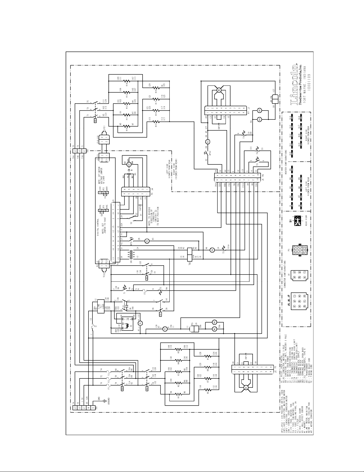
SCHEMATIC
MODEL 1621-000-EA, 1628-000-A, 1629-000-A
Low Profile – 1600 Series Adv Dig Electric S.M. – Int’l
3
pany
TROUBLESHOOTING GUIDE
MODEL 1621-000 EA 230/400 VAC 50 HZ 3 PHASE
MODEL 1628-000 A 220/380 VAC 50 HZ 3 PHASE
MODEL 1629-000 A 240/415 VAC 50 HZ 3 PHASE
NOTE: When checking components on left side of unit, be sure to check for pro per connections in power
connector, (marked P. C. on schematic diagram) located inside motor cover.
SYMPTOM POSSIBLE CAUSE EVALUATION
Oven fan will not
run
No main fan cool
down
No control box
cooling
No automatic
control box cooling
Incoming power supply Check breakers/ reset if required call Power company
if needed.
Fuse, 10 A., main fan Check, replace if necessary.
Fuse holder Check, replace if necessary.
Filter, Power Check for supply voltage to filter. If there is no voltage,
trace wiring back to fuse holder. If there is power in to
the filter, but no power out, replace the filter.
Oven fan switch Check continuity between switch terminals.
20 minute time delay relay Check for supply voltage to terminal #1 and #3, if
there is no voltage, trace wiring back to the power
filter. If voltage is present, check for supply voltage at
terminals #3 to #6, if no voltage is present, trace
wiring back to on/off switch. If there is voltage at #3
and #6, check for voltage at terminals #1 and #2, of
there is no voltage at Terminals #1 and #2, replace
the 20 minute time delay relay.
Relay, main fan motors Check for power to coil of motor relay. If no voltage is
present, trace wiring back to 20 minute time delay
relay. Check for supply voltage to the contact of the
relay. If no voltage is present, trace wiring back to
power filter. If voltage is present, at the relay coil,
check to insure the contacts are closing. Replace
relay as needed.
Hi-limit thermostat(s), control
box
Capacitor(s) Check for opens, shorts, or grounds.
Motor(s), main fan Check for opens, shorts, or grounds.
20 minute time delay relay Check for supply voltage at terminals #1 and #2 while
Fan switch (SEE OVEN FAN WILL NOT RUN.)
Hi-limit thermostat(s) Terminals are normally closed, if open, reset
Relay, main fan motors Check for power to coil of oven fan relay. If no voltage
Cooling fan(s) Supply voltage should now be at these motors. If
Incoming power supply Check circuit breakers, reset if needed. Call power
Terminals are normally closed, if open, reset
thermostat and test oven for proper operation. If it will
not reset, replace thermostat.
is “ON”. Turn “OFF” the main fan switch, supply
voltage should continue to be present for 20 minutes.
If voltage is not present for 20 minutes, replace 20
minute time delay relay.
thermostat and test oven for proper operation. If it will
not reset, replace thermostat.
is present, trace wiring back to hi-limit thermostat.
Check for supply voltage to the contact of the relay. If
no voltage is present, trace wiring back to fuse holder.
If voltage is present, at the relay coil, check to insure
the contacts are closing. Replace relay as needed.
voltage is present, check motor for open, shorts, or
grounds. WITH POWER OFF: check for locked rotor.
com
if needed.
4
Low Profile – 1600 Series Adv Dig Electric S.M. – Int’l
Cooling fan thermostat(s) Check the cooling fan thermostat. (Thermostat closes
at 49°C and opens at 38°C). With the cooling fan
thermostat preheated, check for continuity. If switch is
open, replace.
Fuse, 3 A., cooling fan Check, replace if necessary.
Fuse holder Check, replace if necessary.
Cooling fan(s) Supply voltage should now be at these motors. If
voltage is present, check motor for opens, shorts or
grounds. WITH POWER OFF: Check for locked rotor.
Fan switch Check to see that the fan switch is on. Oven will not heat
Main oven fan Check if main oven fan is operating. If not, refer to
“Oven fan will not run”.
NOTE: These ovens utilize 2 complete /Temperature control systems. Each system will Follow the same
troubleshooting sequence.
Oven control relay Check for line voltage to the relay coil. If no voltage is
present, trace wiring back to the control box hi-limit
thermostat(s). If voltage is present, check to insure
contacts are closing. Replace relay as needed.
Thermostat, oven cavity hi-limit Terminals are normally closed. If open, reset and test
oven for proper operation. If thermostat will not hold
for maximum oven temperature, and oven is not
exceeding maximum temperature dial setting, check
for proper location of capillary bulb in its spring holder
If above checks OK, replace hi-limit.
Contactor, hi-limit Check for line voltage to the contactor coil. If no
voltage is present, trace wiring back to the oven cavity
hi-limit thermostat(s). If voltage is present, check to
insure contacts are closing. Replace contactor as
needed.
Fuse, heater, 50A. Check, replace if necessary.
Fuseholder Check, replace if necessary.
Control transformer Check for supply voltage to the primary of the control
transformer. If no voltage is present, trace wiring back
to the oven control relay. If primary voltage is present,
check for 24VAC at the transformer secondary. If
there is primary voltage, but no secondary voltage,
replace control transformer.
Oven control Check for 24VAC supply to control. If no voltage is
present, trace wiring back to control transformer. If
24VAC is present, check for a read-out on the control
display. If there is 24VAC supplied, but there is no
read-out on the control display, replace the oven
control.
If there is a read-out on the control, set the control to
maximum temperature (see installation operations
manual for temperature adjustment). With the control
set at maximum temperature, check for line voltage at
the heat relay (mercury contactor). If there is voltage
at the heat relay, proceed to “Heat relay” for next
check. If there is no voltage at the heat relay, trace
wiring back to the oven control. If there is no voltage
output at the oven control, check the read-out on the
control. If the control reads “LP FAIL” or “RP FAIL”,
this indicates that the thermocouple has failed or has
become disconnected from the control. “LP FAIL”
indicates a problem with the left thermocouple probe,
and “RP FAIL” indicates a problem with the right
thermocouple probe.
Low Profile – 1600 Series Adv Dig Electric S.M. – Int’l
5
Thermocouple probe Check to be sure that the thermocouple is securely
connected to the oven control. If the thermocouple is
connected to the oven control, and the control
indicates “LP FAIL” or “RP FAIL”, disconnect the
thermocouple from the oven control and measure the
resistance of the thermocouple. The left thermocouple
should read approx. 21Ω. The right thermocouple
should read approx. 11Ω. If these readings are not
achieved, replace the thermocouple. If these readings
are correct, proceed.
Oven control If the thermocouple checks good, but the oven control
display indicates that there is a thermocouple failure,
replace the oven control. If the oven control indicates
a temperature reading but the oven will not heat,
proceed.
Thermocouple WITH POWER ON AND THERMOCOUPLE
ATTACHED TO THE OVEN CONTROL: Measure the
DC millivolt output of the thermocouple. Refer to the
thermocouple chart (located in the “Removal” section
of the manual) for proper millivolt readings. If these
readings are not achieved, replace thermocouple.
Oven control If the thermocouple checks good, but there is no
voltage output to the temperature regulation valve,
replace the oven control. If there is voltage output to
the heat relay, proceed.
Oven air pressure switch Check for supply voltage at the air pressure switch, if
no voltage is present, trace wiring back to the oven
control. Check for supply voltage on both sides of
switch. If voltage is present on one side only, check
for air tube blockage. Adjust air pressure switch. If the
above fails, replace air pressure switch.
Heat relay Check for line voltage supplied to the coil of the heat
relay. If no voltage is present, trace wiring back to the
air pressure switch. If voltage is present, check to be
certain that all of the contacts are closing when the
relay is energized.. Also check for opens or shorts in
the operating coil. Replace temperature regulation
valve as needed.
Heating elements Check the Amp draw on each power lead for proper
load. Check the specification plate for proper rating
information.
If the Amp draw is high or low, check the individual
heating elements for opens, shorts and proper
resistance.
To check the resistance of the elements,
TURN OFF THE POWER!
Remove all wiring from the heating elements and use
an accurate digital meter.
The element resistance should be as follows:
220V – 29 ohms approx.
230V – 32 ohms approx.
240V – 34 ohms approx.
If all readings are not correct, replace heating
elements as needed.
6
Low Profile – 1600 Series Adv Dig Electric S.M. – Int’l
Intermittent heating Thermal overload of main
fan motor(s)
Conveyor will not
Power supply Check for supply voltage at terminals L1 and L2. If
run
Power switch Check continuity between switch terminals. Replace
Fuse, 10 Amp. Check and/or replace.
Fuse holder Check and/or replace.
Hi-limit thermostat(s),
control box
Relay, oven control Check for line voltage to the relay coil. If voltage is not
Control transformer Check for line voltage supply to the primary of the
Conveyor motor Check for line voltage supply to the conveyor motor at
Capacitor, conveyor motor Che c k for shorts or grounds. Replace capacitor as
Switch, conveyor reversing Check continuity between switch terminals, Replace
Oven control If there is supply voltage to the motor. And the motor,
NOTE: Display will indicate
runs, but there is
no speed display
“Belt jam”
Oven control Check for output voltage from the oven control to hall
The main fan motors are equipped with internal
thermal protection and will cease to operate if
overheating occurs. As the motors overheat and then
cool, this will cause the units to cycle on and off
intermittently. Improper ventilation or lack of
preventive maintenance may cause this problem.
Also, most of the problems listed under “Oven will not
heat” can cause intermittent failure.
voltage is not present check breakers.
switch as needed.
Check for voltage on both sides of the switch.
Terminals are normally closed. If open, reset and test
for proper operation. If thermostat will not hold, and
the control box temperature is not exceeding 140°F
(60°C), replace thermostat.
present, trace wiring back to the hi-limit thermostat. If
voltage is present, check to insure contacts are
closing. Replace relay as needed.
control transformer. If no voltage is present, trace
wiring back to the oven power relay. If voltage is
present, check for 24VAC at the transformer
secondary. If there is primary voltage, but no
secondary voltage, replace control transformer.
wire #28 to neutral. If no voltage is present, trace
wiring back to the oven power relay. If voltage is
present and the motor will not run, check the motor
windings for opens or shorts.
WITH POWER OFF: Check the motor windings as
follows:
Grey to black - 116 ohms
Grey to brown - 116 ohms
Brown to black - 230 ohms
needed.
WARNING: Capacitor has a stored charge, discharge
before testing.
switch as needed.
capacitor, and reversing switch check good, replace
the oven control.
Conveyor motor
effect sensor (sensor is located in conveyor motor).
Measure voltage at the motor connector, red wire and
yellow wire. Voltage should be approx. 10VDC. If no
voltage is present, trace wiring back to oven control. If
there is no voltage present at the oven control,
replace the oven control.
Low Profile – 1600 Series Adv Dig Electric S.M. – Int’l
7

Conveyor motor If there is voltage supplied to the hall effect sensor,
check for a frequency output from the hall effect
sensor. Measure frequency across the yellow and
white wires at the motor connector. Frequency
readings should be approx. 20 – 525 Hz. If these
readings are not achieved, replace the conveyor
motor. If the readings are achieved, proceed.
Oven control If the hall effect sensor readings are correct, but there
is no speed indicated on the display, replace the oven
control.
8
Low Profile – 1600 Series Adv Dig Electric S.M. – Int’l

REMOVAL, INSTALLATION & ADJUSTMENTS
MODEL SERIES 1621-000-EA, 1628-000-A, 1629-000-A
CAUTION!
BEFORE REMOVING OR INSTALLING ANY COMPONENT IN THE
IMPINGER OVEN BE SURE TO DISCONNECT ELECTRICAL POWER AND GAS SUPPLY.
AIR PRESSURE SWITCH – REPLACEMENT
A. Remove control panel top.
B. Disconnect wires from switch making note of wire number and location for reinstallation.
C. Remove air tube from switch assembly.
D. Remove switch from control box.
E. Install new switch in reverse, make sure air tube is not blocked or misaligned.
To adjust air pressure switch, remove cover from the switch to expose adjusting screw. To
increase sensitivity, turn screw counter- clockwise; to decrease sensitivity, turn screw
clockwise.
CONVEYOR DRIVE MOTOR – REPLACEMENT
A. Shut off power at main breaker.
B. Remove conveyor.
C. Remove control panel top and front cover.
D. Disconnect wiring from motor and mark for reassembly.
E. Remove sprocket from motor shaft.
F. Remove 4 screws and remove conveyor motor and mounting bracket.
G. Remove mounting bracket from conveyor motor assembly.
H. Reassemble in reverse order.
CAPACITOR, CONVEYOR MOTOR – REPLACEMENT
A. Shut off power at main breaker.
B. Remove control box cover and front panel.
C. Discharge capacitor before removing wires. Mark wires for reassembly.
D. Remove mounting screw and remove capacitor.
E. Reassemble in reverse order.
REVERSING SWITCH – REPLACEMENT
A. Shut off power at main breaker.
B. Remove control box cover and front panel.
C. Disconnect wiring from reversing switch and mark for reassembly.
D. Remove mounting nut and remove reversing switch.
E. Reassemble in reverse order and check system operation.
REVERSING CONVEYOR DIRECTION
A. Shut off power at oven switch.
B. Set reversing switch in the other position.
C. Turn oven “on” and check for proper operation.
FUSEHOLDER – REPLACEMENT
A. Shut off power at main breaker.
B. Remove appropriate control box cover.
Low Profile – 1600 Series Adv Dig Electric S.M. – Int’l
9
 Loading...