

PARTS & SERVICE MANUAL
Impinger Low Profile – Advantage Digital Series
Domestic Models
MODELS:
Please note that the model numbering system changed
March 2007. The chart below shows the old model
numbering system and its matching new model number.
Old Model Number
1600-000-A
1601-000-A
New Model Number
→
1600-00z-U-Kxxxx
→
1601-00z-U-Kxxxx
→
P/N: L371150
REV: 10.22.09
Lincoln Foodservice Products, LLC
1111 North Hadley Road
Fort Wayne, Indiana 46804
Telephone: 260.459.8200
Fax: 888.790.8193
Technical Support: 800.678.9511
lincolnfp.com
SEQUENCE OF OPERATIONS / 1600-000-A, 1601-000-A
SERIAL NUMBERS L28563 and ABOVE
(with push button control)
MODEL 1600-000-A / 120 VAC / 60 HZ / NATURAL GAS
MODEL 1601-000-A / 120 VAC / 60 HZ / L.P. GAS
POWER SUPPLY Electrical power to be supplied to the oven by a three conductor cordset. Voltage from
the black conductor to the white conductor to be 120 VAC.
White conductor is Neutral.
Green conductor is Ground.
CONTROL BOX AUTO
COOL DOWN
MAIN FAN CIRCUIT 120 VAC is permanently supplied to the normally open Power Switch, both normally
BURNER CIRCUIT Closing the Oven Power Relay supplies 120 VAC to the two burner systems.
TEMPERATURE
CONTROL
CONVEYOR DRIVE Closing the main Power Switch supplies 120 VAC through the Oven Power Relay to
When the temperature in either one of the Control Boxes reaches 120°
1.7° C), the Cooling Fan Thermostats will switch power to the Cooling Fans. The
±
thermostats will interrupt the power to the Cooling Fans when temperature falls to
F ± 3° F (37° C ± 1.7° C).
100°
open Cooling Fan Thermostats, and one of the normally open contacts of the Power
Relay. Closing the normally open Power Switch supplies 120 VAC through the Cooling
Fan Motor Fuse, and through both normally closed control box Hi-limit Thermostats
energizing the coil of the Oven Power Relay. These normally open contacts now close
supplying 120 VAC through the 10 Amp Main Fan Motor Fuse to the two Main Fan
Motors and the two Burner Motors. Power is also supplied to the four cooling fan
motors, the Control Transformer, heat, and conveyor control systems.
NOTE: This oven utilizes two complete burner systems. The sequence of operations is
the same for each system. 120 VAC is supplied through the Centrifugal Switch of the
Main Fan Motor (this switch closes when the Main Fan reaches approximately 1600
R.P.M.) through the 10 Amp Fuse, to the Ignition Control, the oven Temperature
Control, and the Burner Transformer. As the Burner Blower reaches approximately
1600 R.P.M., its internal Centrifugal Switch will close, supplying 24 VAC to the Ignition
Control. The Ignition Control operates on both 24 VAC and 120 VAC. When the Ignition
Control is energized by 24 VAC, 120 VAC is switched to the Hot Surface Igniter for 45
seconds for Hot Surface Igniter warm up. The igniter glows red, 24 VAC is switched to
the Gas Valve which opens, and ignition should occur. If ignition does not occur in 6
seconds, the control will lock out. To recycle after lockout, turn the Power Switch off for
45 seconds and then turn back on.
When the Centrifugal Switch of the Main Motor Fan closes, power is applied to the
oven Control. The Oven Control is set to the desired temperature. The thermocouple
will provide varying millivolts to the Oven Control. The Oven Control supplies 120 VAC
to the Temperature Regulation Valve at intermittent intervals to maintain the desired
temperature. The display on the Oven Control will indicate when the Temperature
Control Valve is energized.
NOTE: The display also indicates oven temperature.
the Conveyor Motor and to the primary of the Control Transformer. Secondary voltage,
24 VAC, is supplied to the Oven Control. Setting the Control to the desired time outputs
voltage through a Reversing Switch to the Conveyor Motor.
NOTE: The conveyor system uses a Magnet and a Hall Effect Sensor to prove
operation of the Conveyor Motor. If the Conveyor Motor is not running, “BELT JAM” is
indicated on the display.
F ± 3° F (49° C
2
Low Profile – 1600 Series Advantage Digital Service Manual – Domestic
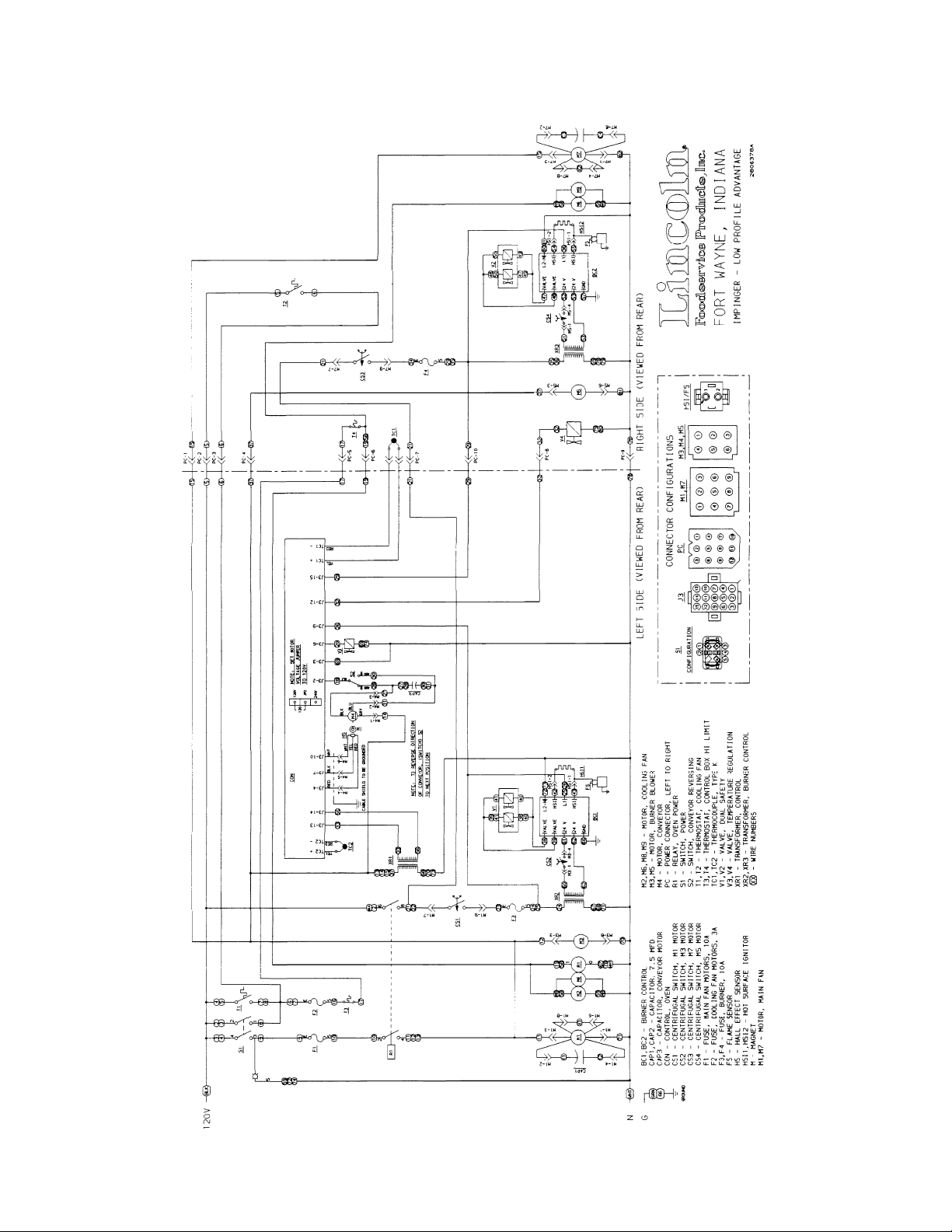
SCHEMATIC DIAGRAM
1600-000-A, 1601-000-A SERIAL NUMBER L28563 AND ABOVE
Low Profile – 1600 Series Advantage Digital Service Manual – Domestic
3
TROUBLESHOOTING GUIDE
GAS OVENS
MODEL 1600-000-A NATURAL GAS 120 VAC. 60 HZ. 1 PHASE
MODEL 1601-000-A LP GAS 120 VAC. 60 HZ. 1 PHASE
NOTE: When checking components on left side of oven, be sure to check for proper connections in power
connector, (marked P.C. on schematic diagram) located inside motor cover.
SYMPTOM POSSIBLE CAUSE EVALUATION
Oven fan will not run Incoming power
supply
Power switch Check continuity between switch terminals. Replace switch as
Fuse, 10 Amp Check, replace if necessary.
Fuse holder Check, replace if necessary.
Fuse, 3 Amp Check, replace if necessary.
Fuse holder Check, replace if necessary.
Hi-limit thermostat(s),
control box
Relay, oven power Check for 120 VAC to the relay coil. If voltage is not present,
Motor, main fan Check for opens, shorts or grounds. WITH POWER OFF: turn
Capacitor Check for shorts or grounds. WARNING: Capacitor has a stored
No control box cooling Incoming power Check circuit breakers, reset if required. Check power plug to be
Power switch Check continuity between switch terminals. Replace switch as
Fuse, 3 Amp Check, replace if necessary.
Fuse holder Check, replace if necessary.
Hi-limit thermostat(s),
control box
Cooling fan(s) 120 VAC should now be at the fan motor. If voltage is not
No automatic control box
cooling
Cooli ng fan
Fuse, 3 Amp Check, replace if necessary.
Fuse holder Check, replace if necessary.
Hi-limit thermostat(s)
Incoming power
supply
thermostat(s)
control box
Check circuit breakers, reset if required. Check power plug to be
sure it is firmly in receptacle. Measure the incoming voltage. Call
power co. if needed.
needed.
Check for voltage on both sides of the switch. Terminals are
normally closed. If open, reset and test oven for proper operation.
If thermostat will not hold, and control box temperature is not
exceeding 140°F (60°C), replace thermostat
Trace wiring back to the hi-limit thermostat. If voltage is present,
check to insure contacts are closing. Check for 120 VAC supplied
to terminal #2 of the relay. If voltage is not present at terminal #2,
trace wiring back to the 10 Amp fuse. Replace relay as needed.
fan blade to check for locked rotor.
charge, discharge before testing.
sure it is firmly in receptacle. Call power co. if needed.
needed.
Check for voltage on both sides of the switch. Terminals are
normally closed. If open, reset and test oven for proper
operation. If thermostat will not hold and control box temperature
is not exceeding 140°F (60°C), replace thermostat.
present, trace wiring back to hi-limit thermostat. Check motor for
opens, shorts or grounds. WITH POWER OFF: Check for locked
rotor.
Check circuit breakers, reset if required. Check power plug to be
sure it is firmly in receptacle. Call power co. if required.
Check the cooling fan thermostat. (thermostat closes at 120°F
and opens at 100°F) With the cooling fan thermostat preheated,
check for continuity. If switch is open, replace thermostat.
Check for voltage on both sides of switch. Terminals are
normally closed. If open, reset and test oven for proper
operation. If thermostat will not hold, and control box
4
Low Profile – 1600 Series Advantage Digital Service Manual – Domestic
temperature is not exceeding 140° F (60°C), replace thermostat.
Cooling fan(s) 120 VAC should be at the motor. If voltage is not present, trace
wiring back to hi-limit thermostat. Check motor for opens, shorts
or grounds. WITH POWER OFF: Check for locked rotor.
Oven will not heat Gas supply Check for adequate gas supply and closed manual gas valves.
Also check flexible gas line connection for any damage.
Main fan If not operating, refer to “Oven fan will not run”.
NOTE: These ovens utilize 2 complete burner/temperature control systems. Each system will follow the same
troubleshooting sequence.
Oven power relay Check for 120 VAC to the relay coil. If voltage is not present,
trace wiring back to the control box hi-limit. If voltage is present,
check to insure contacts are closing. Check for 120 VAC
supplied to terminal #6 of the relay. If voltage is not present at
terminal #6, trace wiring back to the power source. Replace
relay as needed.
Centrifugal switch of
main fan motor
Check for 120 VAC supplied to the centrifugal switch. If no
voltage is present, trace wiring back to the oven power relay. If
voltage is supplied to the centrifugal switch, and the motor is
running, but there is no voltage out of the centrifugal switch,
replace the main fan motor.
NOTE: See schematic diagram for proper wire numbers on
motors.
Fuse, burner 10Amp Check, replace if necessary.
Fuse holder Check, replace if necessary.
Burner blower motor Check for 120 VAC supplied to burner blower motor. If voltage is
not present, trace wiring back to oven power relay. If voltage is
present and motor does not run, replace burner blower motor.
WITH POWER OFF: Check for locked rotor.
Burner transformer Check for 120 VAC to the primary of the 24 VAC burner
transformer. If voltage is not present, trace wiring back to the
burner fuse. If voltage is present, check for 24 VAC at the
transformer secondary. If no secondary voltage is present,
replace the transformer.
Centrifugal switch of
burner blower motor
Check for 24 VAC to the centrifugal switch of burner blower
motor (see schematic diagram for proper wire numbers). If no
voltage is present, trace wiring back to the burner transformer. If
voltage is present, check for 24 VAC at the output of the
centrifugal switch. If there is no output, and the burner blower
motor is running, replace the burner blower motor.
Ignition control Check for 24 VAC supply to the ignition control at terminals 24V
and 24Vgnd. If voltage is not present, trace wiring back to the
centrifugal switch. Check for 120 VAC supply to the ignition
control at terminals L1 and L2. If no voltage is present, trace
wiring back to burner fuse. If the above checks are okay,
proceed. The ignition control should switch 120 VAC to the hot
surface igniter, across the two terminals marked HSI. If no
voltage is present, replace the ignition control.
Hot surface igniter
(located inside
burner assy.
If 120 VAC is present at HSI terminals, visually check to see that
the hot surface igniter is heating (igniter may be viewed through
port in the end of burner tube). The igniter should glow bright
red. Check all connections to be sure they are tight. If the igniter
does not heat, replace hot surface igniter.
Low Profile – 1600 Series Advantage Digital Service Manual – Domestic
5

Ignition control After 45 seconds of hot surface igniter pre-heat, the ignition
control will switch 24 VAC to the gas control valves. Check for
24 VAC output from the ignition control, across terminals
marked “valve” and “valve gnd”. If no voltage is present, replace
the ignition control.
NOTE: The ignition control contains a safety lockout circuit. If a
flame is not detected within 6 seconds after the gas control
valve is energized, the ignition control will lockout. To reset, turn
the power switch “off”, wait 45 seconds and switch the system
“on” to retry ignition.
Gas control valves Check for 24 VAC supplied to the gas control valves. If voltage
is present, the valves should open. Check for gas pressure at
the pressure tap, located in the gas piping just prior to the
burner. If there is no gas pressure, and the voltage is supplied to
the valves, check piping for obstructions. If there are no
obstructions, replace gas control valves.
Flame will not stay lit Hot surface igniter The ignition control will keep the gas control valves energized
for 6 seconds. At the end of 6 seconds, the hot surface igniter
must sense a flame, or the ignition control will go into lockout.
(The ignition control requires a minimum of 0.8 micro-amps DC)
To check the flame sensing operation, connect a digital
multimeter (capable of measuring DC micro-amps) between the
“GND burner” terminal on ignition control and the ground wire.
NOTE: This is a current measurement and the meter must be
connected in series.
If these readings are not achieved, check bypass orifice for
obstructions, if bypass orifice is clear, replace the hot surface
igniter.
NOTE: The DC micro-amp test must be conducted with the oven
in low flame (bypass) operation. Set the temperature control to
its lowest setting.
Power supply If there is sufficient micro-amp current, but the flame will not stay
lit, check for proper polarity of the 120 VAC power supply.
Ignition control If there is sufficient micro-amp current, and the 120 VAC polarity
is correct, but the flame will not stay lit, replace the ignition
control.
NOTE: check for proper ground connection of the ignition
control.
NOTE: Flame should
be lit at this time
Low flame is on, but no
main flame
Control transformer Check for 120 VAC supply to the primary of the control
transformer. If no voltage is present, trace wiring back to the
oven power relay. If voltage is present, check for 24 VAC at the
transformer secondary. If there is primary voltage but no
secondary voltage, replace control transformer.
6
Low Profile – 1600 Series Advantage Digital Service Manual – Domestic
Oven control Check for 24 VAC supply to control. If no voltage is present,
trace wiring back to control transformer. If 24 VAC is present,
check for a read-out on the control display. If there is 24 VAC
supplied, but there is no read-out on the control display, replace
the oven control.
If there is a read-out on the control, set the control to maximum
temperature (see installation operations manual for temperature
adjustment). With the control set at maximum temperature,
check for 120 VAC at temperature regulation valve. If there is
voltage at the temperature regulation valve, proceed to
“temperature regulation valve” for next check. If there is no
voltage at the temperature regulation valve, trace wiring back to
the oven control. If there is no voltage output at the oven control,
Check the read-out on the control. If the control reads “LP FAIL”
or “RP FAIL”, this indicates that the thermocouple has failed or
has become disconnected from the control. “LP FAIL” indicates
a problem with the left thermocouple probe, and “RP FAIL”
indicates a problem with the right thermocouple probe.
Thermocouple Check to be sure that the thermocouple is securely connected to
the oven control. If the thermocouple is connected to the oven
control, and the control indicates “LP FAIL” or “RP FAIL”,
disconnect the thermocouple from the oven control and measure
the resistance of the thermocouple. The left thermocouple
should read approx. 21Ω. The right thermocouple should read
approx. 11Ω. If these readings are not achieved, replace the
thermocouple. If these readings are correct, proceed.
Oven control If the thermocouple checks good, but the oven control display
indicates that there is a thermocouple failure, replace the oven
control. If the oven control indicates a temperature reading but
the oven will not heat, proceed.
Thermocouple WITH POWER ON AND THERMOCOUPLE ATTACHED TO
THE OVEN CONTROL: Measure the DC millivolt output of the
thermocouple. Refer to the thermocouple chart (located in the
“Removal” section of the manual) for proper millivolt readings. If
these readings are not achieved, replace thermocouple.
Oven control If the thermocouple checks good, but there is no 120VAC output
to the temperature regulation valve, replace the oven control. If
there is 120VAC output to the temperature regulation valve,
proceed.
T emperature
regulation valve.
Check for 120VAC supplied to temperature regulation valve. If
voltage is present, listen for valve to open and close. Also check
for opens or shorts in the operating coil. Replace temperature
regulation valve as needed.
Intermittent heating Thermal/overload of
main fan and burner
blower motors
The main fan motors and burner blower motors are equipped
with internal thermal protection and will cease to operate if
overheating occurs. As the motors overheat and then cool, this
will cause the heating systems to cycle on and off intermittently.
Improper ventilation or lack of preventive maintenance may
cause this problem. Also, most of the problem listed under
“Oven will not heat” can cause intermittent failure.
Conveyor will not run Power supply Check for incoming voltage at line 1 to neutral. There should be
a voltage reading of 120VAC. If not present, check circuit
breakers.
Power switch Check continuity between switch terminals. Replace switch as
needed.
Fuse, 10 Amp Check, replace if necessary.
Fuse holder Check, replace if necessary.
Low Profile – 1600 Series Advantage Digital Service Manual – Domestic
7
Hi-limit thermostat(s),
control box
Check for voltage on both sides of the switch. Terminals are
normally closed. If open, reset and test oven for proper
operation. If thermostat will not hold, and control box
temperature is not exceeding 140°F (60°C), replace thermostat
Relay, oven power Check for 120 VAC to the relay coil. If voltage is not present,
Trace wiring back to the hi-limit thermostat. If voltage is present,
check to insure contacts are closing. Check for 120 VAC
supplied to terminal #2 of the relay. If voltage is not present at
terminal #2, trace wiring back to the 10 Amp fuse. Replace relay
as needed.
Control transformer Check for 120 VAC supply to the primary of the control
transformer. If no voltage is present, trace wiring back to the
oven power relay. If voltage is present, check for 24 VAC at the
transformer secondary. If there is primary voltage but no
secondary voltage, replace control transformer.
Conveyor motor Check for 120 VAC supply to the conveyor motor at wire #14 to
neutral. If no voltage is present, trace wiring back to the primary
of the control transformer. If voltage is present and the motor will
not run, check the motor windings for opens or shorts.
WITH POWER OFF: Check the motor windings as follows:
Grey to black - 38Ω approx.
Grey to blue - 38Ω approx.
Blue to black - 75Ω approx.
If any of the above fails, replace conveyor motor.
Cap acitor, conveyor
motor
Check for shorts or grounds. Replace capacitor as needed.
WARNING: Capacitor has a stored charge, discharge before
testing.
Switch, conveyor
reversing
Check continuity between switch terminals. Replace switch as
needed.
Oven control If there is 120VAC supplied to the motor, and the motor,
capacitor, and reversing switch check good, replace the oven
control.
Conveyor motor runs,
but there is no speed
NOTE: Display will
indicate “Belt Jam”
display
Oven control Check for output voltage from oven control to hall effect sensor
(sensor is located in conveyor motor). Measure voltage at the
motor connector, red wire and yellow wire. Voltage should be
approx. 10VDC. If no voltage is present, trace wiring back to
oven control. If there is no voltage present at the oven control,
replace the oven control.
Conveyor motor If there is voltage supplied to the hall effect sensor, check for a
frequency output from the hall effect sensor. Measure frequency
across the yellow and white wires at the motor connector.
Frequency reading should be approx. 25 – 100 Hz. If these
readings are not achieved, replace conveyor motor. If the
readings are achieved, proceed.
Oven control If the hall effect sensor readings are correct, but there is no
speed indicated on the display, replace the oven control.
8
Low Profile – 1600 Series Advantage Digital Service Manual – Domestic

REMOVAL, INSTALLATION & ADJUSTMENTS
MODEL SERIES 1600 ADVANTAGE SERIAL NUMBER L28563 AND ABOVE
(OVENS WITH PUSH BUTTON CONTROLS)
CAUTION !
BEFORE REMOVING OR INSTALLING ANY COMPONENT IN THE IMPINGER
OVEN BE SURE TO DISCONNECT ELECTRICAL POWER AND GAS SUPPLY
BURNER BLOWER MOTOR - REPLACEMENT
A. Remove appropriate control box cover.
B. Unplug motor connector.
C. Remove three (3) screws from blower tube at burner housing.
D. Remove air shutter assy. from old motor for installation on new motor assy.
E. Reassemble in reverse order and check system operation.
NOTE: CHECK AIR SHUTTER ADJUSTMENT- Should be set at 1/2 open.
HOT SURFACE IGNITER - REPLACEMENT
A. Remove appropriate control box cover.
B. Disconnect gas line at union.
C. Remove four (4) nuts from burner orifice bracket.
D. Remove tube for bypass flame.
E. Unplug connector at burner housing.
F. Remove three (3) screws from burner housing end cap and remove
hot surface igniter and burner tube assy.
G. Replace igniter assembly and reassemble in reverse order. CAUTION:
USE CARE NOT TO DAMAGE NEW IGNITER.
NOTE: Check all gas line fittings for leaks. Make sure connector is seated properly.
CONVEYOR DRIVE MOTOR - REPLACEMENT
A. Shut off power at main breaker.
B. Remove conveyor.
C. Remove control panel top and front cover.
D. Disconnect wiring from motor and mark for reassembly.
E. Remove sprocket from motor drive shaft.
F. Remove 4 screws and remove conveyor motor and mounting bracket.
G. Remove mounting bracket from conveyor motor assembly.
CAPACITOR, CONVEYOR MOTOR – REPLACEMENT
REVERSING SWITCH – REPLACEMENT
I. Reassemble in reverse order.
A. Shut off power at main breaker.
B. Remove control box cover and front panel.
C. Discharge capacitor before removing wires. Mark wires for reassembly.
D. Remove mounting screw and remove capacitor.
E. Reassemble in reverse order and check system operation.
A. Shut off power at main breaker.
B. Remove control box cover.
C. Disconnect wiring from reversing switch and mark for reassembly.
D. Remove mounting nut and remove reversing switch.
E. Reassemble in reverse order and check system operation.
Low Profile – 1600 Series Advantage Digital Service Manual – Domestic
9

REVERSING CONVEYOR DIRECTION.
A. Shut off power at oven switch.
B. Set conveyor reversing switch in the other position.
C. Turn oven “on” and check for proper operation.
FUSEHOLDER - REPLACEMENT
A. Remove appropriate control box cover.
B. Remove two (2) wires, note wire number and location.
C. Remove lock nut on back side of fuse holder and push out.
D. Reinstall in reverse order and check system operation.
GAS VALVE, DUAL SAFETY - REPLACEMENT
A. Remove appropriate control box cover.
B. Remove incoming gas line.
C. Remove screws from incoming nipple mounting bracket.
D. Remove incoming nipple.
E. Remove bypass tube assy.
F. Disconnect pipe union.
G. Disconnect wiring from control valve (four [4] push on connectors), make
note of wire numbers and location for reinstallation.
H. Remove gas piping from old valve and install on new one.
I. Reassemble in reverse order and check system operation. Set manifold pressure on gas valve.
Pressure should be 3.5 in W.C. Nat., 10 in W.C. L.P.
NOTE: Check all gas line fittings for leaks, check and adjust manifold pressure.
TEMPERATURE REGULATING VALVE - REPLACEMENT
A. Remove appropriate control box cover
B. Remove bypass tube assy.
C. Remove four (4) nuts from burner orifice bracket.
D. Disconnect pipe union.
E. Disconnect two (2) wires from valve and remove assembly.
F. Remove gas piping from old valve and install on new one.
G. Reassemble in reverse order and check system operation. NOTE: Check
all gas line fittings for leaks and insure valve gas flow is in proper direction .
10
Low Profile – 1600 Series Advantage Digital Service Manual – Domestic

MAIN ORIFICE - REPLACEMENT
A. Remove appropriate control box cover.
B. Remove bypass tube assembly.
C. Remove four (4) nuts from burner orifice bracket.
D. Disconnect pipe union.
E. Remove assembly and replace main orifice.
F. Reassemble in reverse order and check system operation.
NOTE: Check all gas line fittings for leaks.
BYPASS ORIFICE – REPLACEMENT
A. Shut off power at main breaker.
B. Remove appropriate control box cover.
C. Remove pilot tube from bypass orifice and remove orifice.
D. Reassemble in reverse order and check system operation. Check all gas connections for leaks.
ON-OFF SWITCH (POWER) - REPLACEMENT
A. Remove control box cover.
B. Depress spring clips on side of switch and push out.
C. Remove wires from back of switch, note wire number and location.
D. Reassemble in reverse order and check system operation.
NOTE: Make sure switch housing is fully seated in control box housing.
BURNER CONTROL TRANSFORMER, - REPLACEMENT
A. Remove appropriate control box cover.
B. Remove two (2) wires on primary side, note color and location.
C. Remove two (2) wires on secondary side, note color and location.
D. Remove two (2) screws from transformer base and replace assembly.
D. Reinstall in reverse order and check system operation.
CONTROL TRANSFORMER – REPLACEMENT
See “BURNER CONTROL TRANSFORMER” above.
CAPACITOR, MAIN FAN MOTOR (7.5 MFD/370V) - REPLACEMENT
A. Remove appropriate control box cover.
B. Remove two (2) wires from capacitor, note wire number and location.
WARNING: Capacitor has a stored charge, discharge before handling or testing.
C. Cut two (2) tyraps securing capacitor to base and replace.
D. Reinstall in reverse order and check system operation.
RELAY - REPLACEMENT
A. Remove control box cover.
B. Remove wires from relay, note wire numbers and location for reinstallation.
C. Remove two (2) screws from relay base and replace relay.
D. Reassemble in reverse order making sure wire connectors are properly seated.
E. Check system operation.
THERMOSTAT, COOLING FAN - REPLACEMENT
A. Remove appropriate control box cover.
B. Remove two (2) wires from thermostat, note wire number and location.
C. Remove two (2) mounting screws and replace thermostat.
D. Reassemble in reverse order and check system operation.
Low Profile – 1600 Series Advantage Digital Service Manual – Domestic
11

HIGH LIMIT THERMOSTAT - REPLACEMENT
A Remove appropriate control box cover.
B. Remove two (2) wires from thermostat, note wire numbers and location for reinstallation.
C. Remove screws from bracket and remove thermostat.
D. Reassemble in reverse order and check system operation.
NOTE: Depress reset button to insure thermostat is set for operation.
COOLING FAN MOTOR(S) - REPLACEMENT
A. Remove appropriate control box cover.
B. Remove four (4) mounting screws.
C. Unplug electrical connector and remove fan motor assembly.
E. Reassemble in reverse order and check system operation.
MAIN FAN MOTOR - REPLACEMENT
A. Shut off gas supply and remove gas line and manifold lines from back of oven.
B. Remove screws from motor cover housing and lift off.
NOTE: When ovens are stacked, all motor cover housings are fastened together.
C. Unplug power connector .
D. Unplug thermocouple.
E. Unplug two (2) motor connectors.
F. Remove eight (8) bolts from oven back (4 left, 4 right) and lift out.
G. Remove one (1) screw from fan hub and slide fan blade off of motor shaft.
(Note location of fan blade for reinstallation).
H. Loosen lock nuts on cone. Remove two mounting bolts and remove motor from back assy.
I. Remove four (4) hex head screws from motor mount bracket.
Remove motor mount from motor and reinstall on new motor.
J. Reassemble in reverse order.
NOTE:
1. Make sure motor is centered in back housing.
2. Verify correct location of fan blade and that it is not hitting fan shroud.
3. Make sure all connectors are properly seated and making good contact.
4. When reinstalling gas manifold across back of oven, check all fittings for leaks.
K. Check system operation (allow 30 minute preheat for all checks).
NOTE: Position of the fan on the motor shaft will be 1.875" from the top of the oven
back cone to the blade spider assembly on the fan hub. (See drawing below.)
1.875 INCH
FROM CONE TO
FAN SPIDER
THERMOCOUPLE (TYPE”K”) - REPLACEMENT
A. Remove control box covers. Remove motor cover and remove oven back to access
thermocouple.
NOTE: Removal of oven back assy. is required to replace thermocouples.
B. Remove thermocouple from wire form in oven chamber and remove from chamber.
NOTE: R. H. Thermocouple (viewed from front) is connected directly to the
Oven control, unplug thermocouple from oven control and remove thermocouple.
When changing L.H. Thermocouple (viewed from front), the back motor cover
must also be removed to gain access to the thermocouple connector plug.
12
Low Profile – 1600 Series Advantage Digital Service Manual – Domestic

C. Reassemble in reverse order making sure bulb is placed securely
form in the oven chamber.
D. Check system operation, recalibrate as needed. NOTE: The R.H. and L.H.
Thermocouples are different (R.H. one piece, L.H. two piece) and must be ordered
accordingly.
THERMOCOUPLE MEASURMENT
TEMPERATURE D.C. MILLVOLTS (APPROX.)
200° 2.8
250° 4.0
300° 5.1
350° 6.0
400° 7.1
450° 8.2
500° 9.3
550° 10.4
600° 11.5
BEARING, CONVEYOR - REPLACEMENT
A. Remove conveyor from oven and place on a flat work surface.
B. Remove connecting links from conveyor belting. See Installation and Operating
Instructions Manual.
C. Remove conveyor belting from conveyor. Remove drive sprocket from drive shaft
D. Move drive shaft or idle shaft toward end of conveyor, and shaft with bearing will
now slip out of holding bracket.
F. Replace bearing and reassemble.
OVEN CONTROL – REPLACEMENT
A. Shut off power at main breaker.
B. Remove control box cover and front panel.
C. Remove all wiring connections and mark for reassembly.
D. Remove oven control by pulling control from the mounting pins. Remove control from oven.
E. Before installing new oven control, set voltage jumper (located at the bottom center of the
oven control) to the proper voltage (120V/240V) position. Install the four pushbutton extensions
(included with the oven control) by pushing the extensions onto the four set buttons on control.
F. Reassemble in reverse order and check system operation.
G. Set the oven control for the proper operating mode. The 1600 series ovens have dual burner systems.
The oven control must be set to the “Dual oven mode”. Set the control as follows: With the
oven power switch “off”, depress the “temp” and “down” buttons and turn the oven “on”.
Control will indicate “Low Pro”. Release the buttons, The control will indicate “Temp to store”.
Press the “temp” button. The control is now set for dual burner operation.
in the wire
Low Profile – 1600 Series Advantage Digital Service Manual – Domestic
13

GENERAL
1600 ADVANTAGE SERIES
LETTER PART # DESCRIPTION
A 369110 Access Window Assy
B 369929 Window Retainer
C 369926 Window Frame, Bottom
D 369925 Glass, Access Window
E 369927 Window Frame, Top
F 369930 Screw, 10-32x1/4
G 369211 Thumb Screw
H 369058 Baffle
I 370253 Drive Cover L.H.
J 1609 Oven Top
K 370252 Drive Cover L.H.
L 369745 Hinge Assy., Right
M 369723 Door Assy., Small
N 369783 Latch, Spring
O 369717 Finger Retaining Bracket
P 369057 Screw, Finger Retaining Bracket
Q 369501 Latch
R 369238 Leg
S 369030 Caster, High Stand
369390 Caster, Low Stand
T 370167 Baffle, Air Return U.L. L.R. (S/N 35950 & below)
370663** Baffle, Air Return U.L. (S/N 35951 & above)
U 370166 Baffle, Air Return U.R. L.L. (S/N 35950 & below)
370662** Baffle, Air Return U.R. (S/N 35951 & above)
V 370168 Finger Housing T-1, T-3, B-2, B-4 (S/N 35950 & below)
370665*** Finger Housing T-1, T-3, B-2, B-4 (S/N 35951 & above)
370169 Finger Housing T-2, T-4, B-1, B-3 (S/N 35950 & below)
370664*** Finger Housing T-2, T-4, B-1, B-3 (S/N 35951 & above)
W Columnating Plates--See Installation Operations Manual
X 369707 Finger Cover
Y 369740 Handle Assy.
Z 369718 Door Assy., Large
AA 369931 Screw, 8-32x3/8
BB 369746 Hinge Assy. Left
** Units from S/N 35951 and above DO NOT contain lower Air Return Baffles. These units only
contain a total of two (2) Air Return Baffles which are placed above the top finger assemblies.
*** These parts have minor design changes not shown in the exploded view drawing on page 15.
14
Low Profile – 1600 Series Advantage Digital Service Manual – Domestic

Low Profile – 1600 Series Advantage Digital Service Manual – Domestic
15

STAINLESS STEEL ACCESS DOOR
ALL MODELS (SN 0908210000875 AND ABOVE)
LETTER PART NUMBER DESCRIPTION
369110 Access Door Assembly
A 371140 Bracket Assembly, Left
B 371142 Dowel, Access Door
C 370722 Screw
D 371143 8-32 x 3/8 Hx Serr Flng
E 371141 Bracket Assembly, Right
F 370725 Dowel Thread
G 371144 Access Door Frame (top or bottom)
H 370723 Glass
H
A
B
C
D
E
G
F
16
Low Profile – 1600 Series Advantage Digital Service Manual – Domestic

This page intentionally left blank.
Low Profile – 1600 Series Advantage Digital Service Manual – Domestic
17

CONTROL BOX, RIGHT
1600-000-A, 1601-000-A
S/N L28563 AND ABOVE
LETTER PART NUMBER DESCRIPTION
A 369161 Spro cket, Drive
B 370357 Therm ocouple, Type K
C 369757 Main Orifice, Nat.
370279 Main Orifice, L.P.
D 369398 Solenoid Valve
E 369552 Hot Surface Igniter
F 369755 Venturi, Nat.
369642 Venturi, L.P.
G 369401 Air Shutter Assy.
H 369366 Burne r Blower Motor
I 369263 Gas Valve
J 369556 By-Pass Orifice, Nat.
370276 By-Pass Orifice, L.P.
K 370251 Control Box Top R.H.
L 3530 82 Grou nd Lug
M 369537 Powe r Cord
N 369124 Cooli ng Fan
O 369531 Tran sformer, 24 VAC Secondary
P 370359 Reversin g Switch
Q 369192 Cap acitor
R 369012 Fuse Holder
S 369013 Fuse, 3 A
369014 Fuse, 10 A
T 369507 Therm ostat, Cooling Fan
U 369431 Therm ostat, Control Box Hi-Limit
V 370352 Cap acitor, Conveyor Motor
W 370353 Conveyo r Motor
X 369532 Ignition Control
Y 370354 Facia, Label
Z 370355 Control, Oven
AA 370256 Side Panel R.H.
BB 369805 Switch, Power
CC 369523 Relay
Not shown 370495 Bracket, cooling fan, RH S/N L32631 and above
18
Low Profile – 1600 Series Advantage Digital Service Manual – Domestic

Low Profile – 1600 Series Advantage Digital Service Manual – Domestic
19

CONTROL BOX, LEFT
1600-000-A, 1600-000-A
S/N L28563 AND ABOVE
LETTER PART # DESCRIPTION
A 370358 Thermocouple with Extension, Type K
for S/N L28563 and Above
B 369507 Therm ostat, Cooling Fan
C 369431 Therm ostat, Control Box Hi-Limit
D 369532 Ignition Control
E 369531 Tran sformer, 24 VAC
F 369012 Fuse Holder
G 369014 Fuse, 10 A
H 369192 Cap acitor
I 369124 Cooli ng Fan
J 369556 By-Pass Orifice, Nat.
370276 By-Pass Orifice, L.P.
K 369263 Gas Valve
L 369366 Burne r Blower Motor
M 369401 Air Shutter Assy.
N 369552 Hot Surface Igniter
O 369755 Venturi, Nat.
369642 Venturi, L.P.
P 369398 Solenoid Valve Nat/LP
Q 369757 Main Orifice, Nat.
370279 Main Orifice, L.P.
R 370272 Side Panel L.H.
S 370250 Control Box Top, L.H.
Not shown 370496 Bracket, cooling fan, LH S/N L32631 and above
20
Low Profile – 1600 Series Advantage Digital Service Manual – Domestic

Low Profile – 1600 Series Advantage Digital Service Manual – Domestic
21

OVEN BACK
1600 ADVANTAGE SERIES
LETTER PART # DESCRIPTION
A 369547 Wire Form Thermostat Bulb
B 369725 Fan, Clockwise Rotation
C 369776 Fan Shroud
D 369777 Stand-Off
E 369778 Rear Wall Assy.
F 369761 Motor Mount
G 369726 Motor, Main Fan 120V 60 Hz
H 1627 Duct Cap
I 369033 Motor Clamp
J 370245 Rear Duct
K 370246 Manifold Assy.
L 369724 Fan, Counter-Clockwise Rotation
22
Low Profile – 1600 Series Advantage Digital Service Manual – Domestic

Low Profile – 1600 Series Advantage Digital Service Manual – Domestic
23

CONVEYOR
1600 ADVANTAGE SERIES
LETTER PART # DESCRIPTION
369830 Complete Conveyor
A 369816 Conveyor Belting
370092 Belt, 1 Foot Section
B 369825 Retaining Ring
C 369813 Conveyor Bearing Block
D 369314 Roll, Conveyor, Notched
E 369812 Conveyor Idler Shaft
F 369160 Conveyor Pan Stop
G 369814 Connecting Link
H 369811 Conveyor Drive Shaft
J 369161 Roller Chain Sprocket
K 369806 Crumb Pan
L 370050 Conveyor Frame
M 370247 Drive Chain
24
Low Profile – 1600 Series Advantage Digital Service Manual – Domestic

Low Profile – 1600 Series Advantage Digital Service Manual – Domestic
25

This page intentionally left blank.
26
Low Profile – 1600 Series Advantage Digital Service Manual – Domestic

This page intentionally left blank.
Low Profile – 1600 Series Advantage Digital Service Manual – Domestic
27

28
Low Profile – 1600 Series Advantage Digital Service Manual – Domestic
 Loading...