

Page 1

PARTS & SERVICE MANUAL
Impinger I Advantage Digital Series - Electric
International Models
MODELS:
Please note that the model numberi ng system changed
March 2007. The chart below shows the old model
numbering system and its matching new model number.
Old Model Number
1421-000-E
1454
1455
New Model Number
→
1421-00z-U-Kxxxx
1454-00z-U-Kxxxx
1455-00z-U-Kxxxx
P/N: L-371149
REV: 11.16.09
Lincoln Foodservice Products, LLC
1111 North Hadley Road
Fort Wayne, Indiana 46804
Telephone: 260.459.8200
Fax: 888.790.8193
Technical Support: 800.678.9511
lincolnfp.com
Page 2
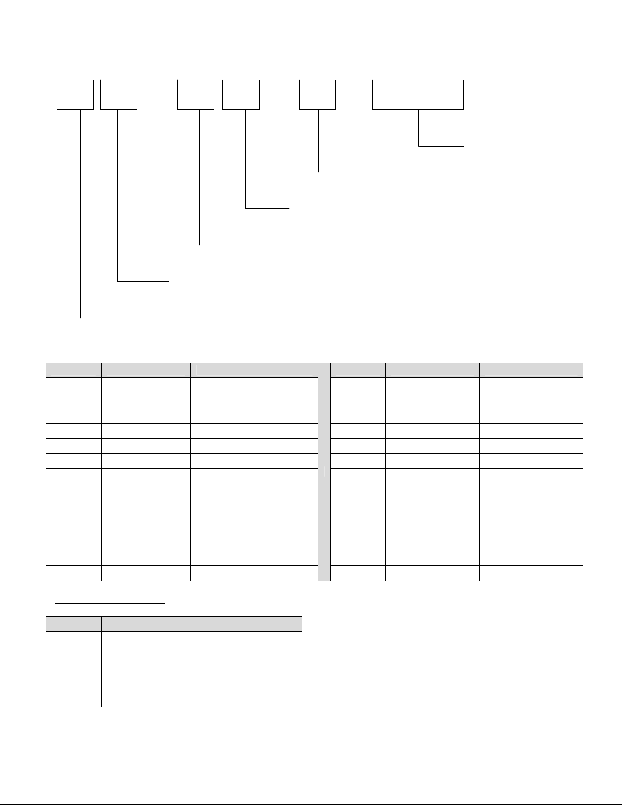
MODEL NUMBER KEY
EXAMPLE: 1421-B00-E-K1801
14 21 - B 00 - E - K1801
Panel Setup Code
Agency Code (i.e. CE & RoHS combined)
Custom Configuration Code (i.e. General Market Version)
Language Code
Indicates change to base assembly (i.e. Natural Gas, 230V, 1 phase, 50 Hz)
Oven Platform Size (i.e. Impinger II)
CODE LANGUAGE COUNTRY CODE LANGUAGE COUNTRY
0 English Dom. & Int. Default N Finnish Finland
B French France/Luxembourg O Restricted --C German Germany P Norwegian Norway
D Italian Italy Q English Japan
E Spanish Spain R Swedish Sweden
F English UK/India/Africa/Hungary S English Australia
G Spanish Mexico/Latin America T Mandarin China
H Portuguese Portugal U Restricted ---
I Not Used --- V English Pacific Rim/Korea
J Danish Denmark W English Middle East
K
L Dutch Netherlands Y Not Used --M Greek Greece Z Not Used ---
Dutch &
French
Belgium X Not Used ---
AGENCY CODE TABLE
CODE AGENCY
N No Agency
E CE & RoHS compliance combined
U US & Canada compliance only
A Advantage style oven to be phased-out
B Australia AGA
2
Impinger I -–Adv Digital – Electric Service Manual - International
Page 3

SEQUENCE OF OPERATION
IMPINGER ADVANTAGE
SERIAL NUMBER N28654 AND ABOVE
(OVENS WITH PUSH BUTTON CONTROLS)
MODEL 1421-000-E 230/400 VAC 50 HZ. 3 PHASE
POWER SUPPLY Electrical power is to be supplied to the oven by a five conductor
service.
Brown conductor is hot.
Black conductor is hot.
Black conductor is hot.
Blue conductor is neutral.
Green conductor is ground.
CONTROL BOX AUTO
COOL DOWN
MAIN FAN CIRCUIT Electrical power is permanently supplied through three 50 A fuses to
HEAT CIRCUIT Closing the oven power switch supplies line voltage through the main
TEMPERATURE CONTROL Closing the oven power switch supplies line voltage, through the EMI
CONVEYOR DRIVE Closing the oven power switch supplies line voltage to the conveyor
When the temperature in the control box reaches 120°F ± 3°F (48.9°C
± 1.7°C), the cooling fan thermostat will switch power to the control
box cooling fan. The thermostat will interrupt power to the cooling fan
when the control box temperature falls to 100°F ± 3°F (37°C ± 1.7°C).
the normally open contacts of the hi-limit contactor. Power is also
supplied, through the 10 Amp motor and control fuse, through the
normally closed control box hi-limit thermostat, to the normally open
oven power switch. Power is also supplied to the control box cooling
fan thermostat. Closing the oven power switch supplies line voltage to
the main fan motor. Closing the oven power switch also supplies line
voltage to the heat circuit and to the primary of the oven control
transformer.
fan air pressure switch, through the normally closed oven cavity hi-limit
thermostat, to the oven control
filter, to the primary of the control transformer and through the air
pressure switch and oven cavity hi-limit, to the oven control.
Secondary voltage, 24VAC, is supplied to the oven control. The oven
control is set to desired temperature. The thermocouple will provide
varying millivolts to the oven control. The oven control supplies line
voltage to the heat contactor at intermittent intervals to maintain
desired temperature. The display on the oven control will indicate
when the heat contactor is energized.
NOTE: The display also indicates oven temperature.
motor and to the primary of the control transformer. Secondary
voltage, 24VAC, is supplied to the oven control. Setting the oven
control to the desired time outputs voltage, through a reversing switch,
to the conveyor motor.
NOTE: The conveyor system uses a hall effect sensor and magnet to
prove operation of the conveyor motor. If the motor is not running,
“BELT JAM” is indicated on the display.
Impinger I -–Adv Digital – Electric Service Manual - International
3
Page 4

SEQUENCE OF OPERATION
IMPINGER ADVANTAGE
SERIAL NUMBER N28654 AND ABOVE
(OVENS WITH PUSH BUTTON CONTROLS)
MODEL 1454 220/380VAC 50 HZ. 3 PHASE
MODEL 1455 240/415VAC 50 HZ. 3 PHASE
POWER SUPPLY Electrical power is to be supplied to the oven by a five conductor
service.
Brown conductor is hot.
Black conductor is hot.
Black conductor is hot.
Blue conductor is neutral.
Green conductor is ground.
CONTROL BOX AUTO
COOL DOWN
MAIN FAN CIRCUIT Electrical power is permanently supplied through three 50 A fuses to
HEAT CIRCUIT Closing the oven power switch supplies line voltage through the main
TEMPERATURE CONTROL Closing the oven power switch supplies line voltage to the primary o f
CONVEYOR DRIVE Closing the oven power switch supplies line voltage to the conveyor
When the temperature in the control box reaches 120°F ± 3°F (48.9°C
± 1.7°C), the cooling fan thermostat will switch power to the control
box cooling fan. The thermostat will interrupt power to the cooling fan
when the control box temperature falls to 100°F ± 3°F (37°C ± 1.7°C).
the normally open contacts of the heat relay. Power is also supplied,
through the 10 Amp motor and control fuse, through the normally
closed control box hi-limit thermostat, to the normally open oven power
switch. Power is also supplied to the control box cooling fan
thermostat. Closing the oven power switch supplies line voltage to the
main fan motor. Closing the oven power switch also supplies line
voltage to the heat circuit and to the primary of the oven control
transformer.
fan air pressure switch, through the normally closed oven cavity hi-limit
thermostat, to the oven control
the control transformer and through the air pressure switch and oven
cavity hi-limit, to the oven control. Secondary voltage, 24VAC, is
supplied to the oven control. The oven control is set to desired
temperature. The thermocouple will provide varying millivolts to the
oven control. The oven control supplies line voltage to the heat
contactor at intermittent intervals to maintain desired temperature. The
display on the oven control will indicate when the heat contactor is
energized.
NOTE: The display also indicates oven temperature.
motor and to the primary of the control transformer. Secondary
voltage, 24VAC, is supplied to the oven control. Setting the oven
control to the desired time outputs voltage, through a reversing switch,
to the conveyor motor.
NOTE: The conveyor system uses a hall effect sensor and magnet to
prove operation of the conveyor motor. If the motor is not running,
“BELT JAM” is indicated on the display.
4
Impinger I -–Adv Digital – Electric Service Manual - International
Page 5
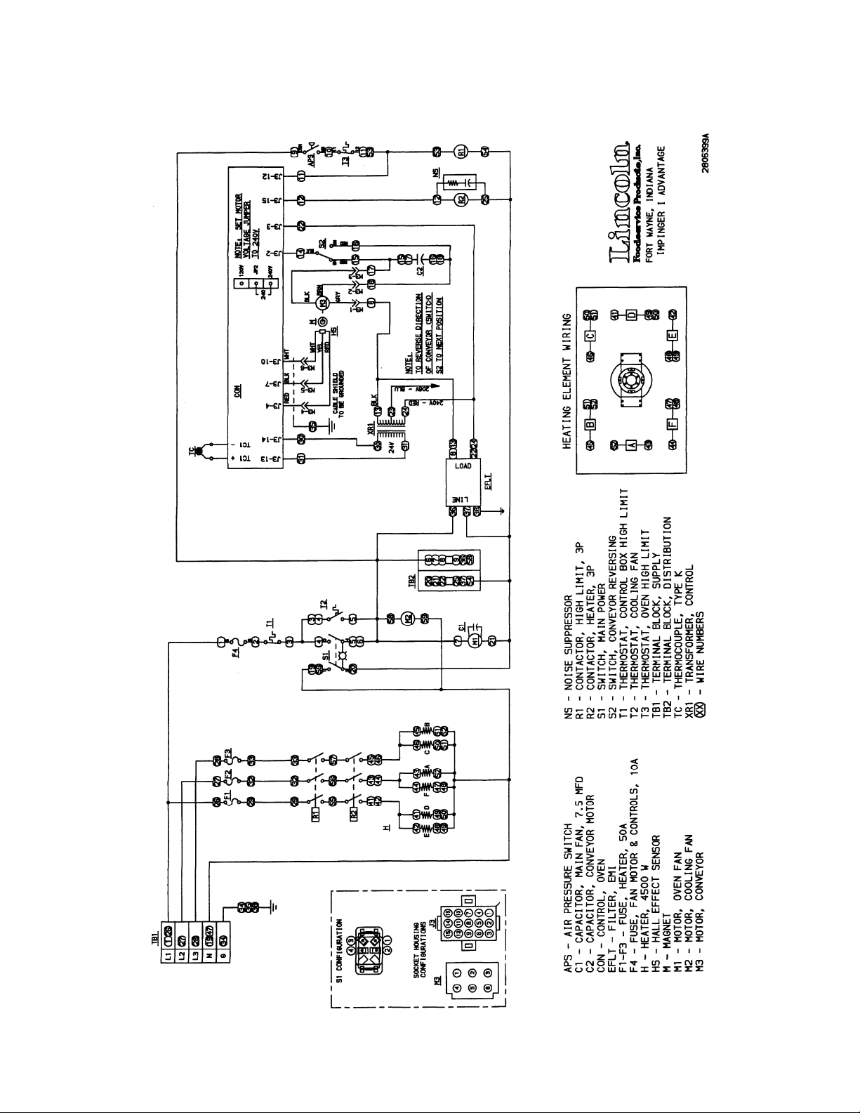
SCHEMATIC DIAGRAM
MODEL 1421-000-E,
SERIAL NUMBER N28654 AND ABOVE
Impinger I -–Adv Digital – Electric Service Manual - International
5
Page 6
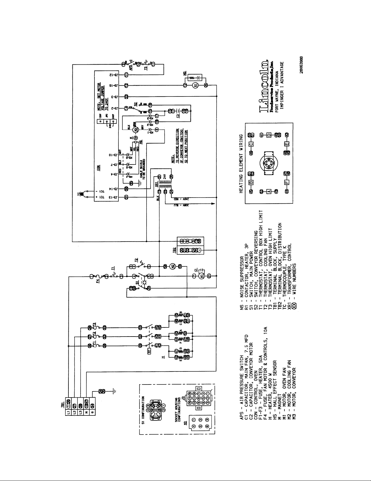
SCHEMATIC DIAGRAM
MODEL 1454, 1455
SERIAL NUMBER N28654 AND ABOVE
6
Impinger I -–Adv Digital – Electric Service Manual - International
Page 7
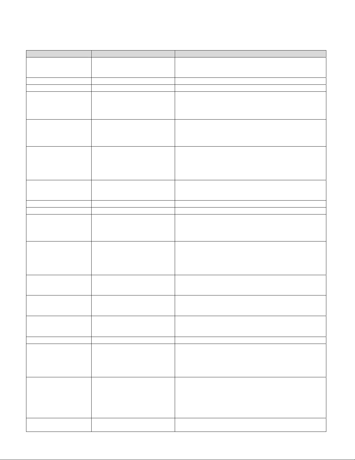
TROUBLESHOOTING GUIDE
IMPINGER ADVANTAGE ELECTRIC OVENS
SERIAL NUMBER N28654 AND ABOVE
(OVENS WITH PUSH BUTTON CONTROLS)
SYMPTOM POSSIBLE CAUSE EVALUATION
Oven fan will not run Incoming power supply Check circuit breaker, reset if required. Check power
plug to be sure it is firmly in receptacle. Measure
incoming power, call power co. if required.
Fuse, 10 Amp Check, replace if necessary.
Fuse holder Check, replace if necessary.
Thermostat, control
box hi-limit
Terminals are normally closed, open at 130°F (55°C). If
open, reset and test for proper operation. If thermostat
will not hold, and control box temperature is not
exceeding 130°F (55°C), replace thermostat.
Switch, oven power Check for line voltage supplied to switch. If no voltage is
present, trace wiring back to fuse holder. Check
continuity between switch terminals. Replace switch as
needed.
Motor, main fan Check for line voltage supplied to motor. If no voltage is
present, trace wiring back to oven power switch. Check
motor for opens, shorts or grounds.
WITH POWER OFF: Turn fan blade to check for locked
rotor.
No control box cooling Incoming power supply Check circuit breaker, reset if required. Check power
plug to be sure it is firmly in receptacle. Measure
incoming power, call power co. if required.
Fuse, 10 Amp Check, replace if necessary.
Fuse holder Check, replace if necessary.
Switch, oven power Check for line voltage supplied to switch. If no voltage
is present, trace wiring back to fuse holder. Check
continuity between switch terminals. Replace switch as
needed.
Cooling fan Check for supply voltage to the cooling fan. If no
voltage is present, trace wiring back to the fuse holder.
If voltage is present and motor does not run, check
motor for opens shorts or grounds.
WITH POWER OFF: Check for locked rotor.
No automatic control
box cooling
Incoming power supply Check circuit breaker, reset if required. Check power
plug to be sure it is firmly in receptacle. Measure
incoming power, call power co. if required.
Cooling fan thermostat Check cooling fan thermostat (thermostat closes at
120°F and opens at 100°F). With cooling fan thermostat
pre-heated, check for continuity
Control box cooling fan
continues to run
Cooling fan thermostat See “Cooling fan thermostat” (NOTE: Thermostat will
remain closed if control box temperature remains above
120°F.
Oven will not heat Main fan If not operating, refer to “Oven fan will not run”
Air pressure switch Check air switch terminals for supply voltage to
terminals NO and COM. If voltage is present on one side
only, check for air tube blockage or misalignment. If
these are okay, adjust air pressure switch or replace
switch as needed.
Oven cavity hi-limit
thermostat
Terminals are normally closed, opens at 660°F (350°C).
If open, reset and test oven for proper operation. If
thermostat will not hold for maximum temperature, and
oven is not exceeding control setting, check for proper
location of the capillary bulb in its spring holder. If above
checks are okay, replace hi-limit thermostat.
Control transformer Check for supply voltage to primary of control
transformer. If no voltage is present, trace wiring back to
Impinger I -–Adv Digital – Electric Service Manual - International
7
Page 8

oven power switch. If voltage is present, check for
24VAC at transformer secondary. If there is primary
voltage, but no secondary voltage, replace control
transformer.
Oven control Check for 24VAC supply to oven control. If no voltage is
present, trace wiring back to control transformer. Check
for supply voltage to oven control. If no voltage is
present, trace wiring back to hi-limit thermostat. If
voltage is present, check for a read-out on the display. If
there is no read-out on the display, replace oven control.
If there is a read-out on the display, set the oven control
to maximum temperature (see installation operations
manual for temperature adjustment). With the oven
control at maximum temperature, check for supply
voltage to the heat contactor. If there is voltage at the
heat contactor, proceed to “Heat contactor “. If there is
no voltage at the heat contactor, trace wiring back to the
oven control. If there is no voltage output at the oven
control, check the read-out on the oven control. If the
oven control reads “PROBE FAIL” this indicates that the
thermocouple has failed or become disconnected from
the oven control
Contactor, hi-limit (Model
1421-000-E only)
Check for supply voltage to contactor coil. If no voltage
is present, trace wiring back to oven cavity hi-limit
thermostat. If supply voltage is present at the coil, check
to see that contacts are closed. If there is voltage to the
coil and the contacts are not closed, replace contactor.
Thermocouple Check to see that the thermocouple is securely
connected to the oven control. If the thermocouple is
connected to the oven control, and the display indicates
“PROBE FAIL”, disconnect the thermocouple from the
oven control and measure the resistance of the
thermocouple. The thermocouple should read approx.
11Ω. If these readings are not achieved, replace the
thermocouple. If these readings are correct, proceed.
Oven control If the thermocouple checks good, but the oven control
display indicates that there is a thermocouple failure,
replace the oven control. If the oven control indicates a
temperature reading, but the oven will not heat, proceed.
Thermocouple WITH POWER ON AND THERMOCOUPLE
ATTACHED TO THE OVEN CONTROL: Measure the
DC millivolt output of the thermocouple. Refer to the
thermocouple chart (located in the “Removal” section of
the manual) for proper millivolt readings. If these
readings are not achieved, replace thermocouple.
Oven control If the thermocouple checks good, but there is no supply
voltage output to the temperature regulation valve,
replace the oven control. If there is supply voltage output
to the heat contactor, proceed.
Heat contactor Check for supply voltage to the heat contactor. If voltage
is present, listen for contacts to open and close. Also
check for opens or shorts in the operating coil. Replace
heat contactor as needed.
Intermittent heating Thermal/overload of main fan
motor
The main fan motor is equipped with internal thermal
protection and will cease to operate if overheating
occurs. As the motor overheats and cool, this will cause
the heating system to cycle on and off intermittently.
Improper ventilation or lack of preventive maintenance
may cause this problem. Also most of the problems
listed under “Oven will not heat” can cause intermittent
failure.
8
Impinger I -–Adv Digital – Electric Service Manual - International
Page 9

Conveyor will not run Incoming power supply Check circuit breaker, reset if required. Check power
plug to be sure it is firmly in receptacle. Measure
incoming power, call power co. if required.
Fuse, 10 Amp Check, replace if necessary.
Fuse holder Check, replace if necessary.
Switch, oven power Check for line voltage supplied to switch. If no voltage
is present, trace wiring back to fuse holder. Check
continuity between switch terminals. Replace switch as
needed.
Control transformer Check for supply voltage to primary of control
transformer. If no voltage is present, trace wiring back to
oven power switch. If voltage is present, check for
24VAC at transformer secondary. If there is primary
voltage, but no secondary voltage, replace control
transformer.
Conveyor motor Check for supply voltage to the conveyor motor at
terminal #8 to neutral. If no voltage is present, trace
wiring back to oven power switch. If voltage is present,
but the motor will not run, check the motor windings for
opens or shorts. If any of the above checks fail, replace
conveyor motor.
Capacitor, conveyor motor Check for shorts o r grounds. Replace capacitor as
needed.
WARNING: Capacitor has a stored charge, discharge
before testing.
Switch, conveyor reversing Check continuity between switch terminals. Replace
switch as needed.
Oven control If there is voltage supplied to the motor, and the motor
capacitor and reversing switch check good, replace the
oven control.
Conveyor motor runs,
but there is no speed
NOTE: Display will indicate
“BELT JAM”
display
Oven control Check for output voltage from oven control to hall effect
sensor (sensor is located in the conveyor motor).
Measure voltage at the motor connector, red wire and
yellow wire. Voltage should be approx. 10VDC. If no
voltage is present, trace wiring back to oven control. If
there is no voltage output at the oven control, replace
oven control.
Conveyor motor If there is voltage supplied to the hall effect sensor,
check for a frequency output from the hall effect sensor.
Measure frequency across the yellow and white wires in
the motor connector. Frequency reading should be
approx. 25-100 Hz. If these readings are not achieved,
replace conveyor motor. If the readings are achieved,
proceed.
Oven control If the hall effect sensor readings are correct, but there is
no speed indicated on the display, replace the oven
control.
Impinger I -–Adv Digital – Electric Service Manual - International
9
Page 10

REMOVAL, INSTALLATION & ADJUSTMENTS
IMPINGER ADVANTAGE SERIES
CAUTION!
BEFORE REMOVING OR INSTALLING ANY COMPONENT IN THE IMPINGER
OVEN BE SURE TO DISCONNECT ELECTRICAL POWER AND GAS SUPPLY
MOTOR, MAIN FAN - REPLACEMENT
1. Shut off power at main breaker.
2. Remove louvered motor cover from back of oven.
3. Remove wireway by taking out the (5) five hex screws.
4. Disconnect wiring from motor.
5. Remove the twelve (12) hex head bolts from the oven back and slide back straight out of the oven.
6. Remove two (2) bolts from fan hub and remove fan from motor shaft.
NOTE: Measure distance from fan blade to rear wall assembly before removal to aid in reassembly.
7. Remove the eight (8) hex head bolts from the motor mount and slide the motor assembly out of the oven back.
8. Remove motor by taking off motor clamp and removing the four (4) mounting nuts and washers.
9. Reassemble in reverse order. When motor mount assembly is set on the oven back, align motor shaft in the center
of the hole. Set fan assembly on the motor shaft.
NOTE: A. Torque specs on bolts (150 in/lb. torque)
B. It is recommended that an anti-seize compound be brushed on to the bolts around
the back and motor mount bracket before assembly.
FAN, MAIN - REPLACEMENT
Shut off power at main breaker.
Remove back assembly. (See MOTOR, MAIN FAN))
Reinstall and locate fan so that the bottom of the fan spider is 1 1/2" from the top of the oven back cone. (See Drawing)
FAN SPIDER
NOTE: MEASUREMENT MUST BE
MADE FROM CONE TO FAN SPIDER
FAN HUB
CONE
CAPACITOR, MOTOR - REPLACEMENT
1. Shut off power at main breaker.
2. Remove motor cover from back of oven.
3. Discharge capacitor.
4. Remove and replace.
COOLING FAN, CONTROL BOX - REPLACEMENT
1. Shut off power at main breaker.
2. Remove control panel top and front cover.
3. Remove four (4) screws from the fan frame.
4. Disconnect cord and plug and remove fan.
5. Reassemble in reverse order.
10
1 1/2 INCH
Impinger I -–Adv Digital – Electric Service Manual - International
Page 11

THERMOSTAT, COOLING FAN - REPLACEMENT
1. Shut off power at main breaker.
2. Remove control panel top and front cover.
3. Remove lead wires and mark for reassembly.
4. Remove two (2) screws and remove thermostat.
5. Reassemble in reverse order.
THERMOSTAT, OVEN CAVITY HI-LIMIT – REPLACEMENT
1. Shut off power at main breaker.
2. Remove control box cover and front panel. Remove conveyor assembly and fingers from oven to aid in removal of
thermostat from oven.
3. Disconnect wires from thermostat and mark for reassembly.
4. Remove thermostat from oven.
5. Reassemble in reverse order and check system operation.
AIR PRESSURE SWITCH – REPLACEMENT
1. Shut off power at main breaker.
2. Remove control panel top and front cover.
3. Disconnect wires from air pressure switch and mark for reassembly.
4. Remove air switch tube from air pressure switch.
5. NOTE: There are two types of air pressure switches used. Remove air pressure switch from its mount.
6. Reassemble in reverse order and check system operation.
7. To adjust air pressure switch, remove cover from switch to expose adjusting screw. To increase sensitivity, turn
screw counter-clockwise. To decrea se sensitivity, turn screw clockwise.
THERMOCOUPLE (TYPE K) - REPLACEMENT
1. Shut off power at main breaker.
2. Remove control panel top and front cover.
3. Slide thermocouple out of oven chamber.
NOTE: Remove conveyor and bottom fingers to aid in removal and installation of thermocouple.
4. Remove two (2) wires from temperature control. Make note of wire numbers or color and
location for reinstallation.
5. Reassemble in reverse order making sure the metal end on the thermocouple is in the wire form in the oven
chamber.
THERMOCOUPLE MEASURMENT
TEMPERATURE D.C. MILLVOLTS (APPROX.)
200° 2.8
250° 4.0
300° 5.1
350° 6.0
400° 7.1
450° 8.2
500° 9.3
550° 10.4
600° 11.5
Impinger I -–Adv Digital – Electric Service Manual - International
11
Page 12

CONTROL TRANSFORMER - REPLACEMENT
1. Shut power off at main breaker.
2. Remove control panel top and front cover.
3. Remove two (2) wires on primary side, note color and location.
4. Remove two (2) wires on secondary side, note color and location.
5. Remove two (2) screws from transformer base and replace assembly.
6. Reinstall in reverse order and check system operation.
CONVEYOR DRIVE MOTOR - REPLACEMENT
1. Shut power off at main breaker.
2. Remove control panel top and front cover.
3. Loosen set screw on conveyor drive sprocket and slide sprocket off shaft.
4. Disconnect motor plug.
5. Remove four (4) screws from motor frame, on control box side, and remove motor assembly.
6. Reassemble in reverse order making sure to align chain sprockets and adjust motor for proper chain tension
(1/2" SAG).
CAPACITOR, CONVEYOR MOTOR – REPLACEMENT
1.Shut off power at main breaker.
2.Remove control box cover and front panel.
3.Discharge capacitor before removing wires. Mark wires for reassembly.
4.Remove mounting screw and remove capacitor.
5.eassemble in reverse order and check system operation.
REVERSING SWITCH – REPLACEMENT
1. Shut off power at main breaker.
2. Remove control box cover and front panel.
3. Disconnect wires from reversing switch and mark for reassembly.
4. Remove mounting nut and remove reversing switch.
5. Reassemble in reverse order and check system operation.
REVERSING CONVEYOR DIRECTION
All ovens leaving our plant are wired to operate conveyors from left to right. To reverse conveyor
direction, use the following procedure.
1. Shut off power at oven switch.
2. Set conveyor reversing switch in the other position.
3. Turn oven “on” and check for proper operation.
ON-OFF SWITCH - REPLACEMENT
1. Shut off power at main breaker.
2. Remove control box cover.
3. Remove access cover.
4. Depress spring clips on side of switch and push out.
5. Remove wires from back of switch, note wire number and location.
6. Reassemble in reverse order and check system operation.
NOTE: Make sure switch housing is fully seated in control box housing.
OVEN CONTROL – REPLACEMENT
A. Shut off power at main bre ake r.
B. Remove control box cover and front panel.
C. Remove all wiring connections and mark for reassembly.
D. Remove oven control by pulling control from the mounting pins. Remove control from oven.
E. Before installing new oven control, set voltage jumper (located at the bottom center of the
oven control) to the proper voltage (120V/240V) position. Install the four pushbutton extensions
12
Impinger I -–Adv Digital – Electric Service Manual - International
Page 13

(included with the oven control) by pushing the extensions onto the four set buttons on control.
F. Reassemble in reverse order and check system operation.
G. Set the oven control for the proper opera t ing mode. The 1400 series ovens use a single temperature control
system. The oven control must be set to the proper operating mode. Set the control as follows: With the oven
power switch “off”, depress the “time” and “up” buttons and turn the oven “on”. Control will indicate
“Imp I or Imp II” Release the buttons. Press the “up” or “down” button until “Imp I” and “temp to store” appears
on the display. Press the “temp” button. The control is now set for Impinger I conveyor and single burner
operation.
FUSE HOLDER – REPLACEMENT
1. Shut off power at main breaker.
2. Remove control box cover.
3. Remove all wiring from fuse holder and mark for reassembly.
4. Remove mounting nut for fuse holder and remove fuse holde r.
5. Reassemble in reverse order and check system operation.
BEARING, CONVEYOR – REPLACEMENT
1. Remove conveyor from oven and place on flat work surface.
2. Remove connecting links from conveyor belt. See Installation and operations manual.
3. Remove conveyor belt from conveyor. Remove drive sprocket from drive shaft if required.
4. Move shaft toward end of conveyor, and shaft with bearings will now slip out of holding bracket.
5. Replace bearing and reassemble in reverse order.
HEAT CONTACTOR – REPLACEMENT
1. Shut off power at main breaker.
2. Remove control box cover and front panel.
3. Remove all wiring from contactor and mark for reassembly.
4. Remove mounting screws and remove contactor.
5. Reassemble in reverse order and check system operation. NOTE: be sure that contactor is not mounted upside
down, as this will cause a constant “on” condition.
HI-LIMIT CONTACTOR – REPLACEMENT
See “HEAT CONTACTOR – REPLACEMENT”
EMI FILTER – REPLACEMENT
1. Shut off power at main breaker.
2. Remove control box cover and front panel.
3. Remove all wiring from filter and mark for reassembly.
4. Remove mounting screws and remove filter.
5. Reassemble in reverse order and check system operation.
HEATING ELEMENT – REPLACEMENT
1. Shut off power at main breaker.
2. Remove back cover.
3. Disconnect wiring from heating element and mark wires for reassembly.
4. Disconnect motor wiring and mark for reassembly.
5. Remove oven back assembly from oven.
6. Remove fan shroud.
7. Remove heating element from oven back.
8. Reassemble in reverse order and check system operation. NOTE: Be sure heating element connection s are tight
.
Impinger I -–Adv Digital – Electric Service Manual - International
13
Page 14

THERMOSTAT, CONTROL BOX HI-LIMIT – REPLACEMENT
1. Shut off power at main breaker.
2. Remove control box cover and front panel.
3. Remove wiring from thermostat and mark for reassembly.
4. Remove mounting screws and remove thermostat.
5. Reassemble in reverse order and check system operation. NOTE: Be sure to press reset button on new
thermostat to set for operation.
14
Impinger I -–Adv Digital – Electric Service Manual - International
Page 15

This page intentionally left blank.
Impinger I -–Adv Digital – Electric Service Manual - International
15
Page 16

GENERAL VIEW
ADVANTAGE SERIES
LETTER PART NUMBER DESCRIPTION
A 369003 Door hinge
B 369110 Access window assembly (NLA – See Access Door Section)
C 369337 Retainer (old style) (NLA – See Access Door Section)
369929 Retainer (new style) (NLA – See Access Door Section)
D 369828 Handle spacer
E 369209 Latch & strike
F 369310 Screw, 6-32 x 3/16” (NLA – See Access Door Section)
G 369308 Bottom, access window (NLA – See Access Door Section)
H 369334 Access door glass (NLA – See Access Door Section)
J 369309 Top, access window (NLA – See Access Door Section)
K 350638 Handle (NLA – See Access Door Section)
L 369311 Handle spacer (2 req.) (NLA – See Access Door Section)
M 369336 Door latch (NLA – See Access Door Section)
N 369906 Screw, 8-32 x 5/8”
O 370110 Door assembly (solid)
P 369157 Door assembly (with window)
Q 1534 Finger support assembly
R 369057 Support bracket pin
S 369643 Strike assembly
T 1009 Oven top
U 369062 Top, control box
V 369140 Compression spring
W 369903 Washer, flat
X 369141 Conveyor hold down bracket
Y 369139 Shoulder screw
Z 369058 Baffle, inlet and outlet
* 369211 Thumb screw (not shown)
AA 369203 Stud, wing head
BB 369749 Chain cover kit (includes AA, CC)
CC 369204 Split ring retainer
DD 369373 Receptacle, snap –in
EE 369748 Bracket, chain cover
FF 369328 Leg, stand
GG 369052 Adjustable leg
HH 369030 Caster, 6”
JJ 369904 Insulation holder assembly
KK 369053 Finger housing
LL Columnating plates
MM 369055 Finger cover
NN 369218 Crumb pan, internal
OO 369926 Window frame, bottom (NLA – See Access Door Section )
PP 369925 Glass, access window (NLA – See Access Door Section)
QQ 369927 Window frame, top (NLA – See Access Door Section)
16
Impinger I -–Adv Digital – Electric Service Manual - International
Page 17

Impinger I -–Adv Digital – Electric Service Manual - International
17
Page 18

CONTROL BOX
1421-000-E, 1454, 1455
LETTER PART # DESCRIPTION
A 369066 Sprocket, 10 tooth
B 370373 Conveyor motor
C 369507 Thermostat, cooling fan
D 369025 Air pressure switch
E 369119 Terminal block
F 369134 Fuse, 50A
G 370163 Terminal block, 5 Pole
H 370387 Filter, EMI
I 370485 Contactor, mercury
J 369838 Thermostat, control box hi-limit
K 357107 Fuse holder
L 369014 Fuse, 10A
M 369378 Cooling fan
N 369331 Finger guard
O 370359 Reversing switch
P 369368 Thermostat, oven cavity hi-limit
Q 370388 Cover, access
R 370360 Capacitor, Conveyor motor
S 4000054 Ground lug
T 369125 Terminal block, 2-pole
U 369427 Transformer, control
V 370362 Thermocouple, type “K”
W 370363 Front cover assembly
X 370354 Facia, label
Y 369432 Switch, on/off
Z 370355 Oven control
AA 7006831 Top, control panel
18
Impinger I -–Adv Digital – Electric Service Manual - International
Page 19

Impinger I -–Adv Digital – Electric Service Manual - International
19
Page 20

OVEN BACK
ADVANTAGE SERIES
GAS AND ELECTRIC
LETTER PART NUMBER DESCRIPTION
A 369808 Cover, motor (gas ovens)
370140 Cover, motor (electric ovens)
B 369214 Motor, main fan (50 Hz.)
C 369033 Motor clamp
D 369215 Motor support assembly
E 369192 Capacitor, 7.5 MFD
F 369306 Oven back assembly, gas oven
G 369646 Stand-off
H 369647 Inlet panel
J 369213 Main fan
K 369547 Bracket, thermostat
M 369287 Heating element, 208V
369315 Heating element, 220V
369122 Heating element, 240V
20
Impinger I -–Adv Digital – Electric Service Manual - International
Page 21

Impinger I -–Adv Digital – Electric Service Manual - International
21
Page 22

CONVEYOR
1450 SERIES
LETTER PART NUMBER DESCRIPTION
369830 Complete conveyor assembly
A 369816 Conveyor belt, 30” Wide
370092 Conveyor belt, 1 ft. section, 30” Wide
369163 Conveyor Belt, 32” Wide (units mfg after 10/2003)
369362
B 369825 Retaining ring
C 369813 Conveyor bearing block
D 369314 Roll, conveyor, notched
E 369812 Conveyor idler shaft
F 369160 Conveyor pan stop
G
H 369811 Conveyor drive shaft
J 369161 Roller chain sprocket
K 369806 Crumb pan
L 370050 Conveyor frame
M 369162 Drive chain
369814
369005
Conveyor Belt, 1 ft. section, 32” Wide
(units mfg after 10/2003)
Connecting link (30 inch wide belt)
Connecting link (32 inch wide belt)
22
Impinger I -–Adv Digital – Electric Service Manual - International
Page 23

Impinger I -–Adv Digital – Electric Service Manual - International
23
Page 24

ACCESS DOOR
ALL MODELS (SN 0908210000875 AND ABOVE)
LETTER PART NUMBER DESCRIPTION
369110 Access Door Assembly
A 371140 Bracket Assembly, Left
B 371142 Dowel, Access Door
C 370722 Screw
D 371143 8-32 x 3/8 Hx Serr Flng
E 371141 Bracket Assembly, Right
F 370725 Dowel Thread
G 371144 Access Door Frame (top or bottom)
H 370723 Glass
H
A
B
C
D
E
G
F
24
Impinger I -–Adv Digital – Electric Service Manual - International
Page 25

This page intentionally left blank.
Impinger I -–Adv Digital – Electric Service Manual - International
25
Page 26

This page intentionally left blank.
26
Impinger I -–Adv Digital – Electric Service Manual - International
Page 27

This page intentionally left blank.
Impinger I -–Adv Digital – Electric Service Manual - International
27
Page 28

28
Impinger I -–Adv Digital – Electric Service Manual - International
 Loading...