


SERVICE MANUAL
IMPINGER COUNTERTOP OVEN
MODEL 1300 SERIES
Lincoln Foodservice Products, LLC
1111 North Hadley Road
Fort Wayne, Indiana 46804
United States of America
Phone : (800) 374-3004
U.S. Fax: (888) 790-8193 • Int’l Fax: (260) 436-0735
Technical Service Hot Line
(800) 678-9511
www.lincolnfp.com
1300svcman REV: 7/02/07

SERVICE AND PARTS MANUAL
1300 SERIES
IMPINGER COUNTERTOP OVEN
TABLE OF CONTENTS
TABLE OF CONTENTS..............................................................................................................................................2
SEQUENCE OF OPERATIONS.................................................................................................................................3
SCHEMATIC 1301, 1302 S/N 3000352 & BELOW................................................................................................5
SCHEMATIC 1301, 1302 S/N 3000353 TO 3000480.............................................................................................6
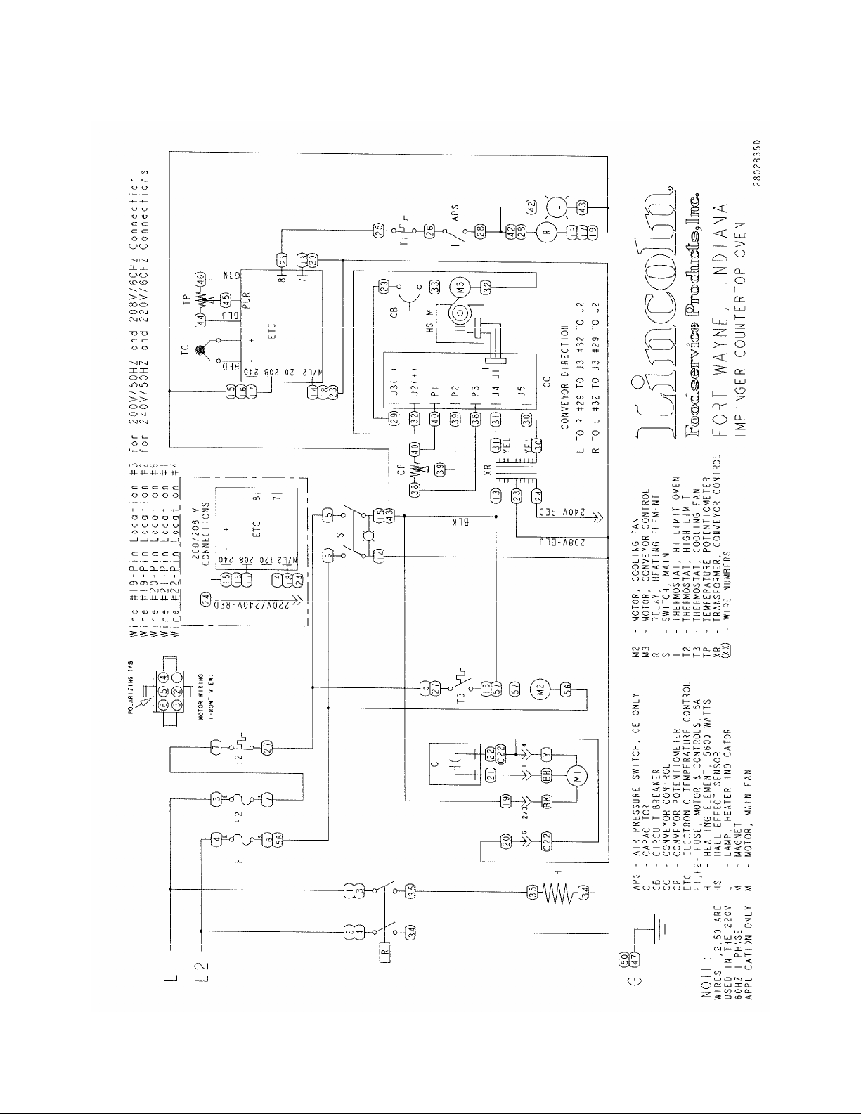
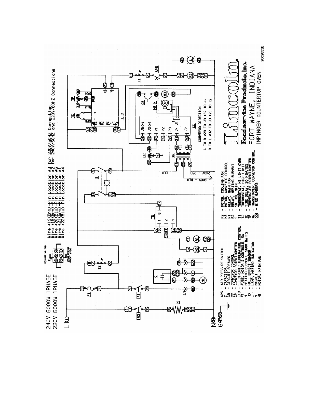
SCHEMATIC 1300, 1301, 1302, 1310 S/N 3000481 TO 3018980 ........................................................................7
SCHEMATIC 1300, 1301, 1302, 1310 S/N 3018981 -3022633.............................................................................8
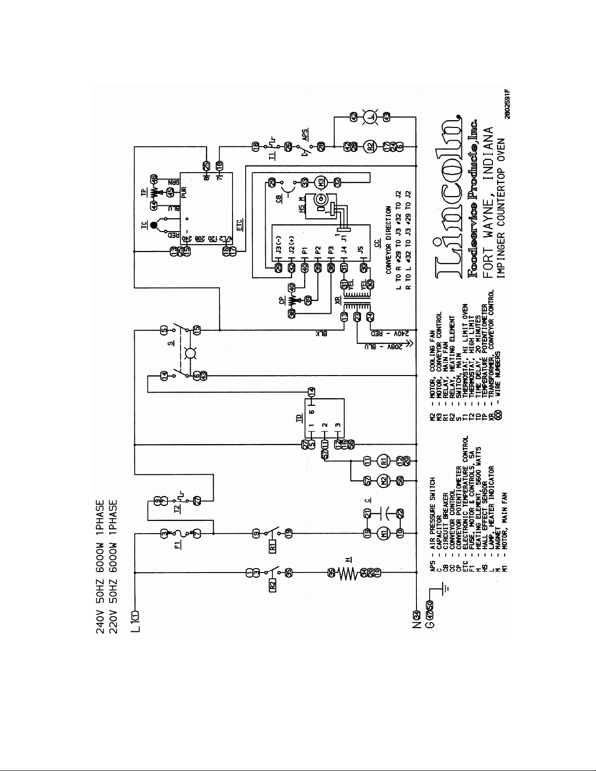
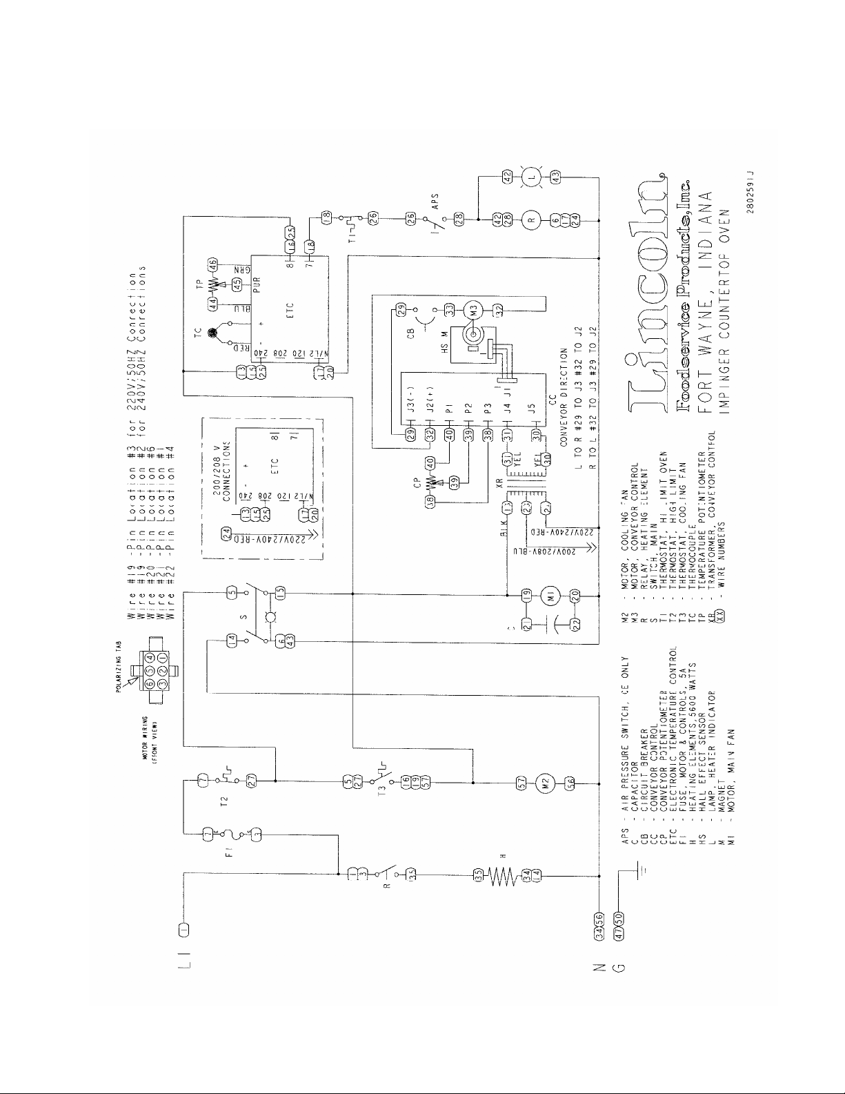
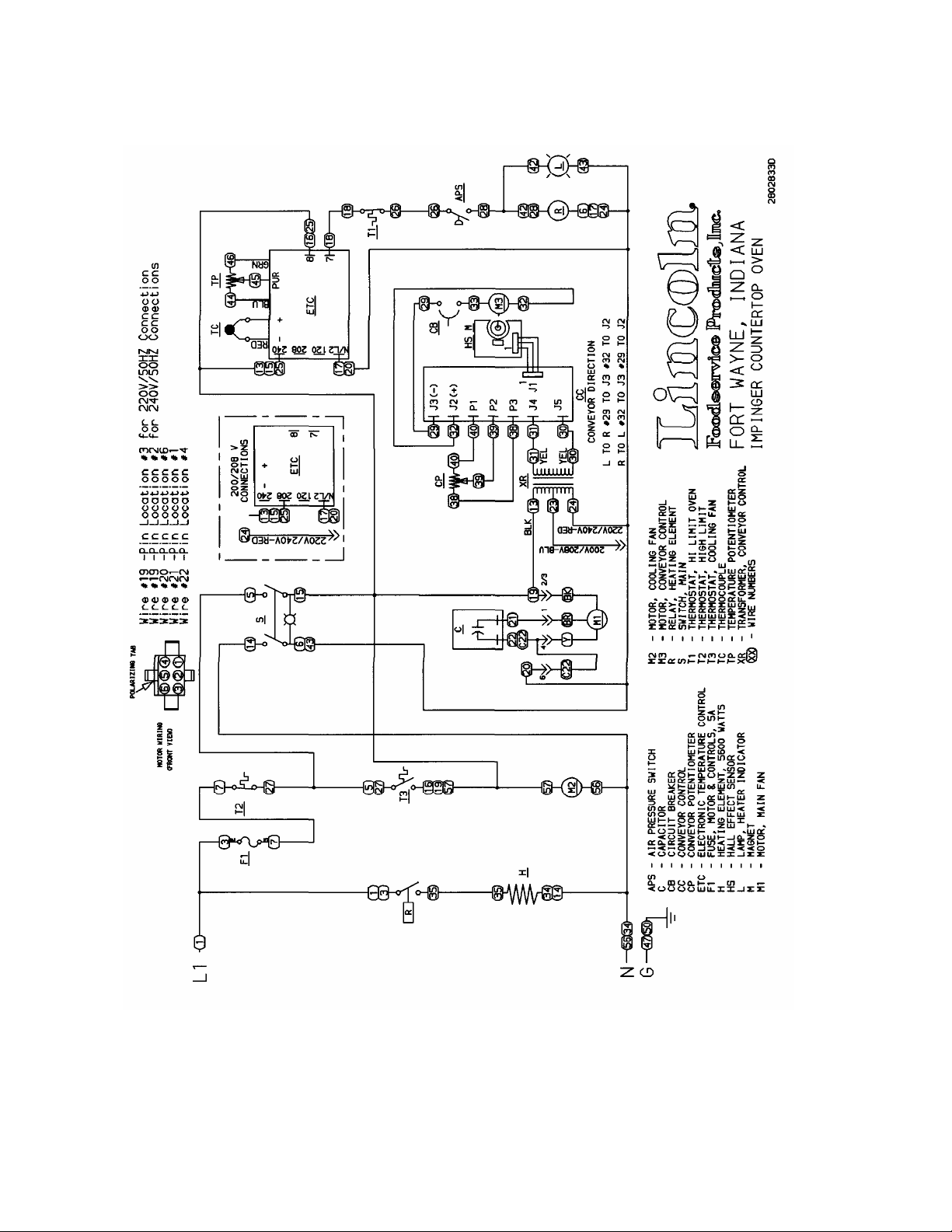
SCHEMATIC 1300, 1301, 1301-4, 1302, 1302-4, 1310 S/N 3022634 TO 3043630..............................................9
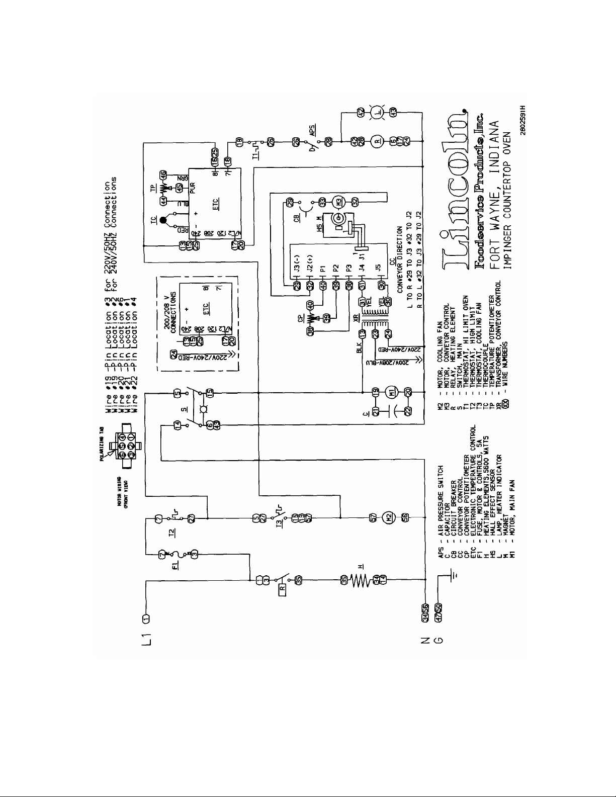
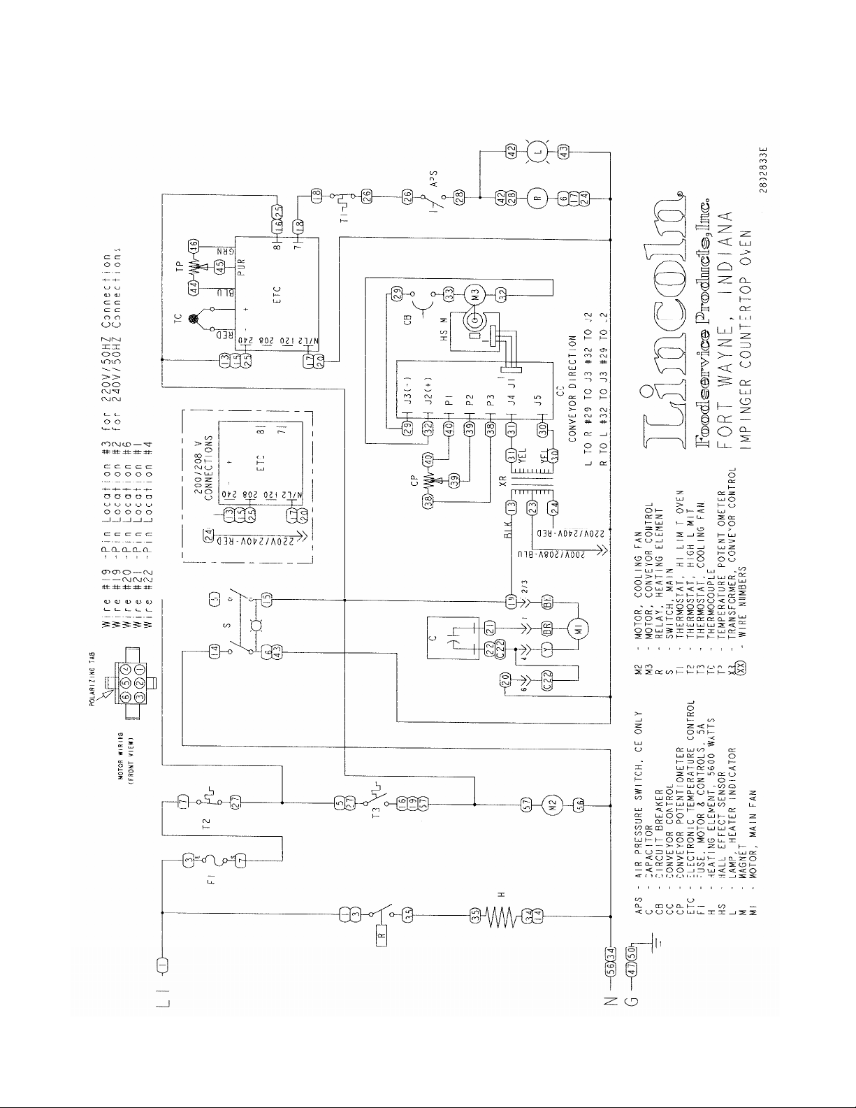
SCHEMATIC 1300, 1301, 1301-4, 1302, 1302-4, 1310 S/N 3043631 & ABOVE................................................10
SCHEMATIC 1301-4, 1302-4 S/N 3018980 & BELOW........................................................................................11
SCHEMATIC 1301-4, 1302-4 S/N 3018981 TO 3043630....................................................................................12
SCHEMATIC 1301-4, 1302-4 S/N 3043631 & ABOVE ........................................................................................13
SCHEMATIC 1303,1304 S/N 3018980 & BELOW...............................................................................................14
SCHEMATIC 1303,1304 S/N 3018981 TO 3043630............................................................................................15
SCHEMATIC 1303,1304 S/N 3043631 & ABOVE................................................................................................16
SCHEMATIC 1304-4 S/N 3018980 & BELOW.....................................................................................................17
SCHEMATIC 1304-4 S/N 3018981 TO 3043630 .................................................................................................18
SCHEMATIC 1304-4 S/N 3043631 & ABOVE......................................................................................................19
SCHEMATIC 1305,1306 S/N 3018980 & BELOW...............................................................................................20
SCHEMATIC 1305,1306 S/N 3018981 TO 3043630............................................................................................21
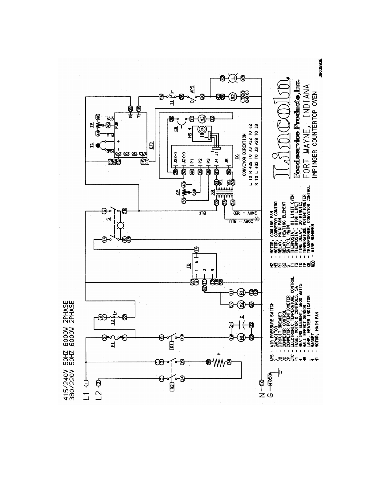
SCHEMATIC 1305,1306 S/N 3043631 & ABOVE................................................................................................22
SCHEMATIC 1305-4 S/N 3018980 & BELOW.....................................................................................................23
SCHEMATIC 1305-4 S/N 3018981 TO 3043630 .................................................................................................24
SCHEMATIC 1305-4 S/N 3043631 & ABOVE......................................................................................................25
SCHEMATIC 1307 S/N 3018980 & BELOW........................................................................................................26
SCHEMATIC 1307 S/N 3018981 TO 3043630.....................................................................................................27
SCHEMATIC 1307 S/N 3043631 & ABOVE.........................................................................................................28
SCHEMATIC 1308,1309,1311 S/N 3018980 & BELOW...................................................................................
SCHEMATIC 1308,1309,1311 S/N 3018981 TO 3043630 ..................................................................................30
SCHEMATIC 1308,1309,1311 S/N 3043631 & ABOVE ......................................................................................31
SCHEMATIC 1308-4 S/N 3018980 & BELOW.....................................................................................................32
SCHEMATIC 1308-4 S/N 3018981 TO 3043630 .................................................................................................33
SCHEMATIC 1308-4 S/N 3043631 & ABOVE......................................................................................................34
SCHEMATIC 1312-000-E S/N 3018980 & BELOW .............................................................................................35
SCHEMATIC 1312-000-E S/N 3018981 & ABOVE..............................................................................................36
SCHEMATIC 1313-000-E S/N 3018980 & BELOW .............................................................................................37
SCHEMATIC 1313-000-E S/N 3018981 & ABOVE..............................................................................................38
SCHEMATIC 1314-F24-E S/N 3018980 & BELOW.............................................................................................39
SCHEMATIC 1314-F24-E S/N 3018981 & ABOVE..............................................................................................40
TROUBLESHOOTING GUIDE.................................................................................................................................41
REMOVAL, INSTALLATION, AND ADJUSTMENT .................................................................................................45
CONVEYOR CONTROL BOARD - REPLACEMENT.......................................................................................48
GENERAL – 1300 SERIES......................................................................................................................................54
GENERAL – 1300 SERIES PARTS BLOW-UP...................................................................................................55
CONTROL COMPARTMENT – 1300 SERIES ........................................................................................................56
CONTROL COMPARTMENT – 1300 SERIES BLOW - UP.................................................................................57
BACK – 1300 SERIES..............................................................................................................................................58
BACK – 1300 SERIES BLOW - UP......................................................................................................................59
STANDARD CONVEYOR – 1300 SERIES..............................................................................................................60
EXTENDED CONVEYOR – 1300 SERIES..............................................................................................................61
...29
CounterTop – 1300 Series Service Manual
2

1300 200 VAC 60 HZ 1 PHASE
1301 208 VAC 60 HZ1 1 PHASE
1302 240 VAC 60 HZ 1 PHASE
1303 220 VAC 50 HZ 1 PHASE
1304 240 VAC 50 HZ 1 PHASE
1305 380/220 VAC 50 HZ 1 PHASE
1306 415/240 VAC 50 HZ 1 PHASE
1307 200 VAC 60 HZ 3 PHASE
1308 380/220 VAC 50 HZ 3 PHASE
1309 415/240 VAC 50 HZ 3 PHASE
1310 220 VAC 60 HZ 1 PHASE
1311 380/220 VAC 60 HZ 3 PHASE
1312-000-E 400/230 VAC 50 HZ 3 PHASE
1313-000-E 400/230 VAC 50 HZ 2 PHASE
1314-F24-E 240 VAC 50 HZ 1 PHASE
POWER SUPPLY
1300/1301/1302 1303/1304/1314-F24-E 1305/1306
Black – Hot
Red – Hot
Green - Ground
1307 1308/1309/1311 1310
Red – Hot
Black - Hot
Orange – Hot
Green - Ground
1312-000-E 1313-000-E
Black (3) – Hot
Blue – Neutral
Green/Yellow – Ground
SEQUENCE OF OPERATIONS
MODEL CTI
(Electrical power supplied to the oven:)
Brown - Hot
Blue – Neutral
Green/Yellow-Ground
Brown – Hot
Black (2) – Hot
Blue – Neutral
Green/Yellow – Ground
Black (2) – Hot
Blue – Neutral
Green/Yellow - Ground
Brown – Hot
Black – Hot
Blue – Neutral
Green/Yellow-Ground
Brown – Hot
Black – Hot
Green/Yellow-Ground
CounterTop – 1300 Series Service Manual
3

MAIN FAN CIRCUIT
Electrical power is permanently supplied through the Control Box Hi-Limit to terminal one (1) of the 20Minute Timer. When the DPST Fan Switch is closed, the timer is enabled. This energizes terminal two
(2) of timer, which supplies power to the Coil of the Fan Relay and the Cooling Fan Motor. The normally
open contacts of the Fan Relay now close energizing the Main Fan Motor. Closing the Main Fan Switch
also supplies power to the Conveyor, Control Transformer, and the Electronic Temperature Control
Board.
TEMPERATURE CONTROL CIRCUIT
Closing the Main Fan Switch supplies power to the Temperature Control Board. The Temperature
Control Potentiometer is adjusted to the desired temperature. Power is then supplied through the
normally closed High Limit Thermostat and the Main Fan Air Switch to the Coil of heating element relay.
When the contacts of the heating element relay are closed, power is then applied to the 5600W Heating
Element. The Thermocouple provides varying millivolts to the Temperature Control Board. The
temperature control board supplies voltage to the Coil of the heating element relay at intermittent
intervals to maintain desired temperature.
CONVEYOR DRIVE
Closing the Main Fan Switch supplies voltage to the primary of the Transformer, the secondary of the
Transformer then supplies 24 VAC to the Conveyor Control Board. AC voltage is converted to DC
voltage and is supplied to the Drive Motor at terminals J3(-) and J2(+). Adjustment of the Speed Control
Potentiometer will change resistance at terminals P1, P2, and P3 varying the DC voltage to the motor.
The speed of the conveyor motor will increase or decrease as the DC voltage from the board increases
or decreases respectively.
NOTE: The conveyor control uses a sensor and magnet mounted on the conveyor motor that senses
the motor speed. Any change in motor load (± RPM) is detected by the sensor and the voltage to the
motor is adjusted accordingly.
CounterTop – 1300 Series Service Manual
4
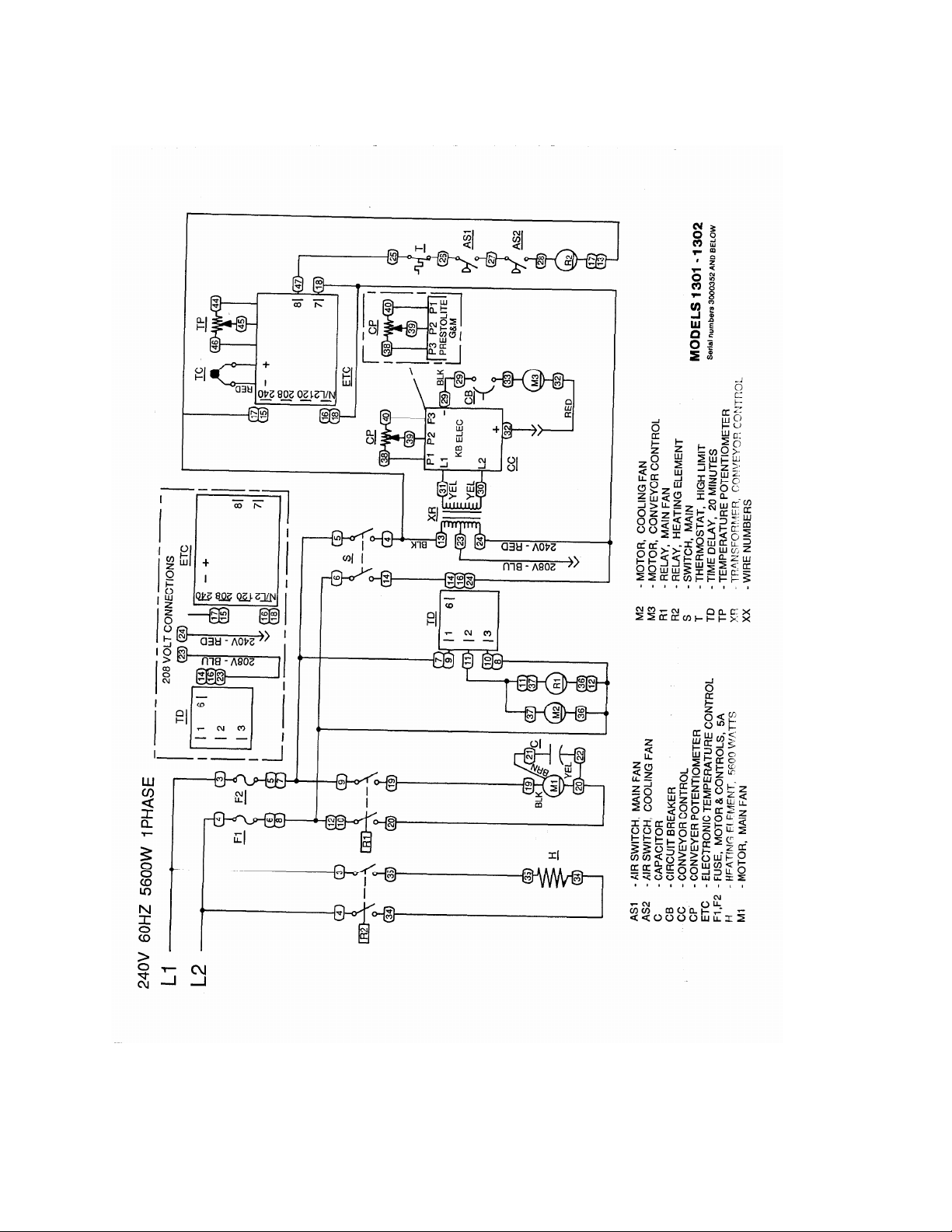
SCHEMATIC 1301, 1302 S/N 3000352 & BELOW
CounterTop – 1300 Series Service Manual
5
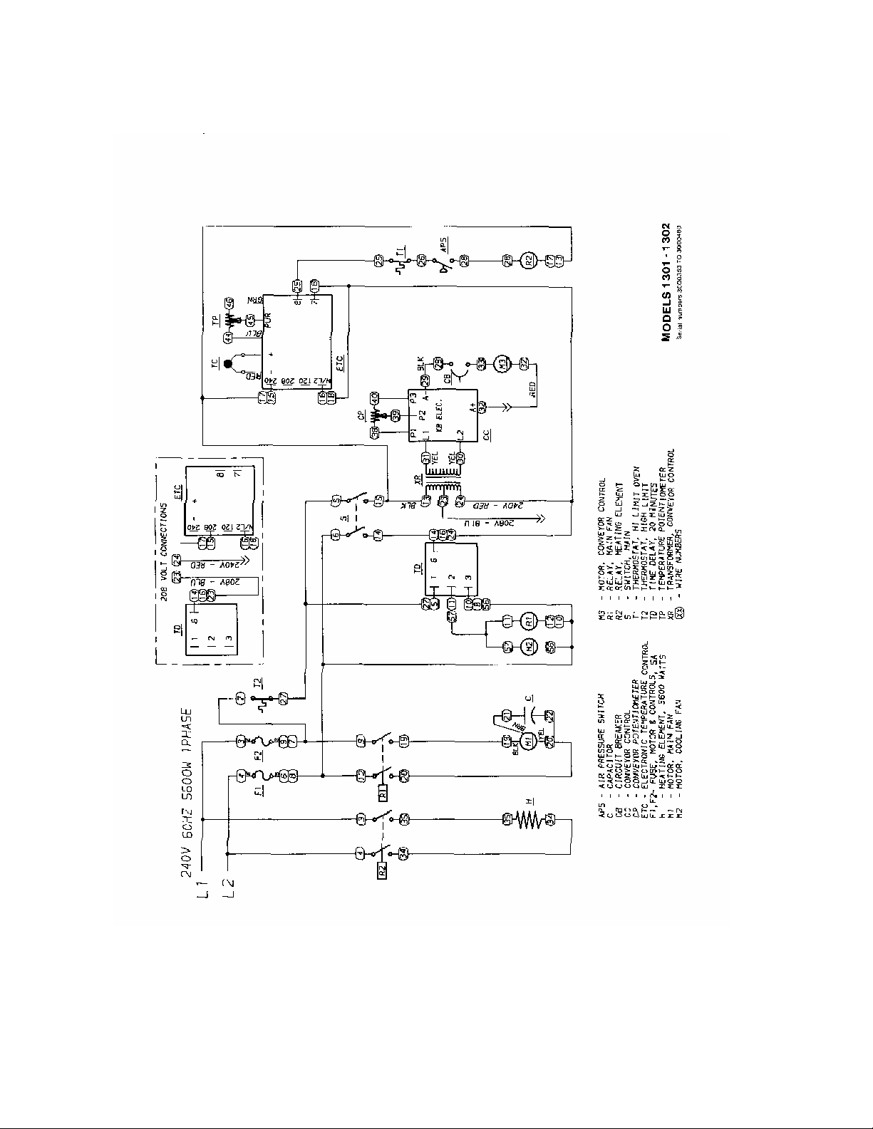
SCHEMATIC 1301, 1302 S/N 3000353 TO 3000480
CounterTop – 1300 Series Service Manual
6
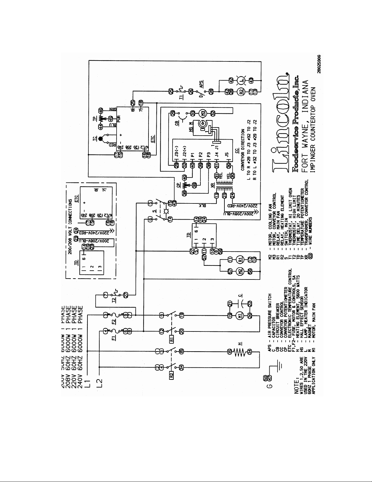
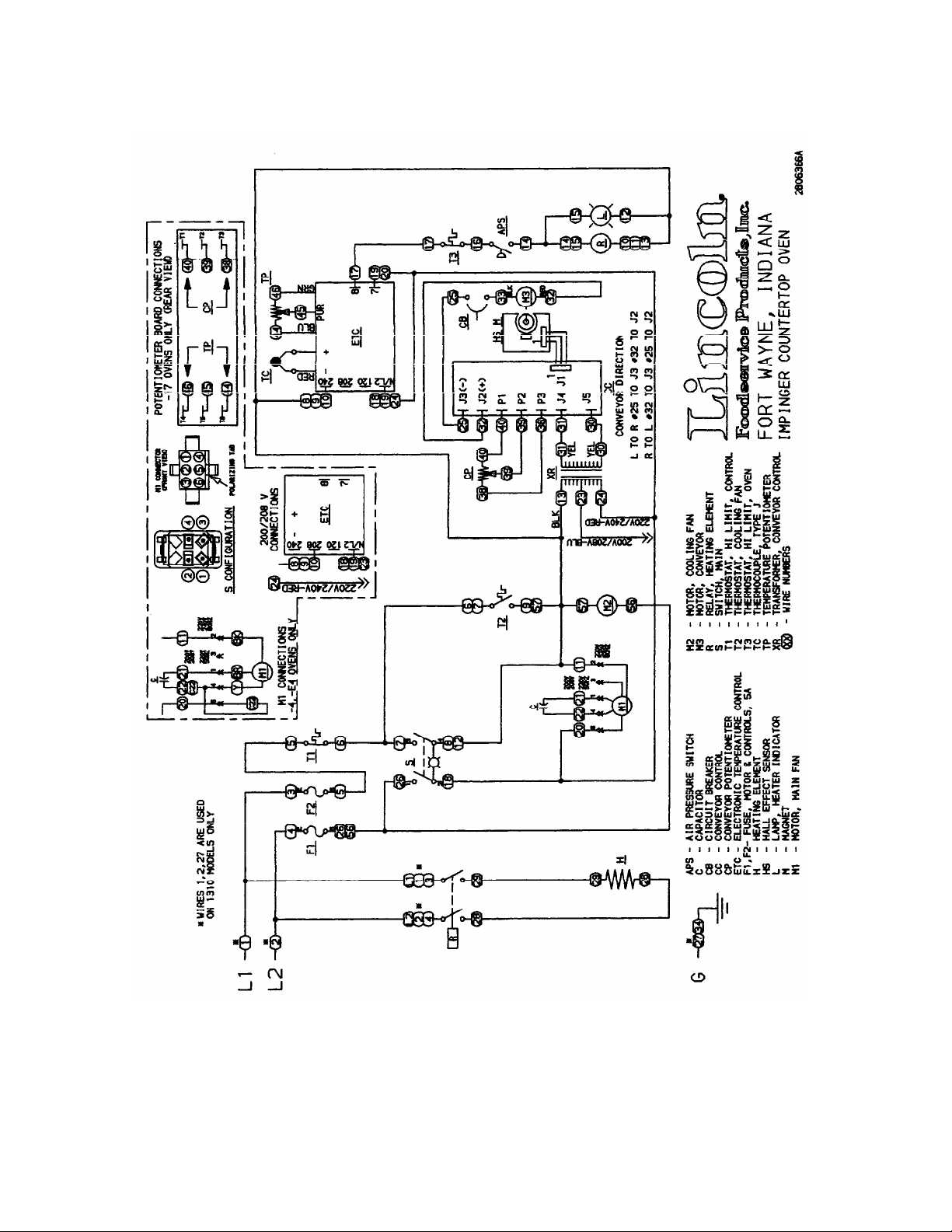
SCHEMATIC 1300,1301,1302,1310 S/N 3000481 TO 3018980
CounterTop – 1300 Series Service Manual
7
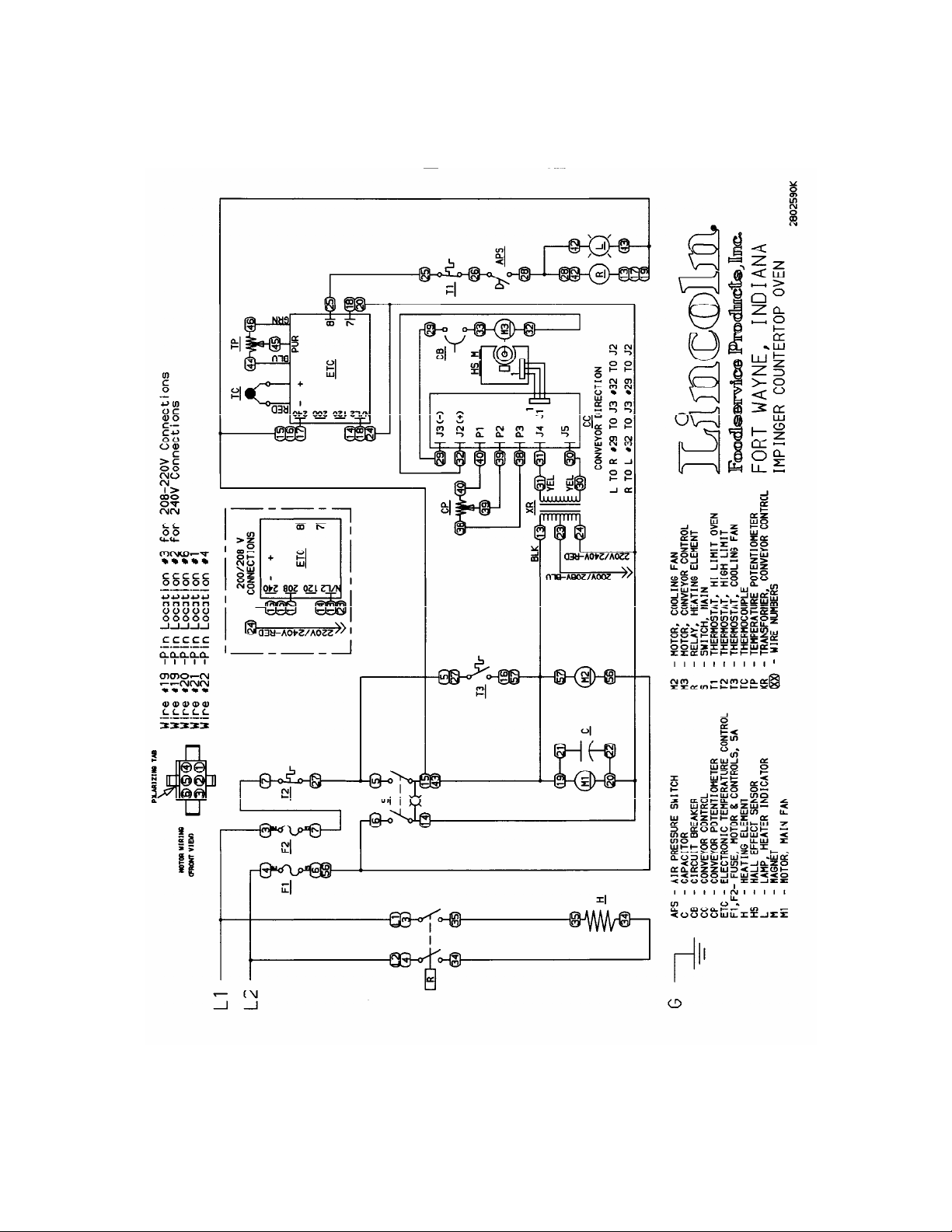
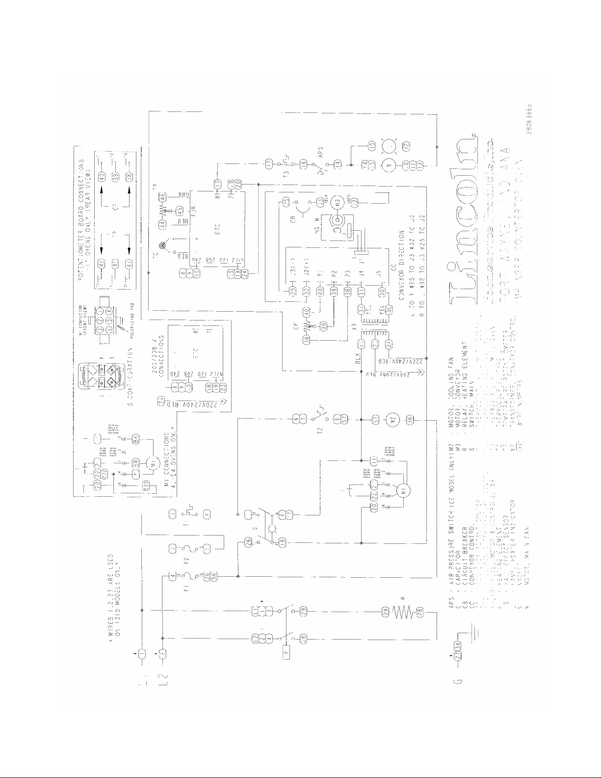
SCHEMATIC 1300,1301,1302,1310 S/N 3018981 –3022633
CounterTop – 1300 Series Service Manual
8
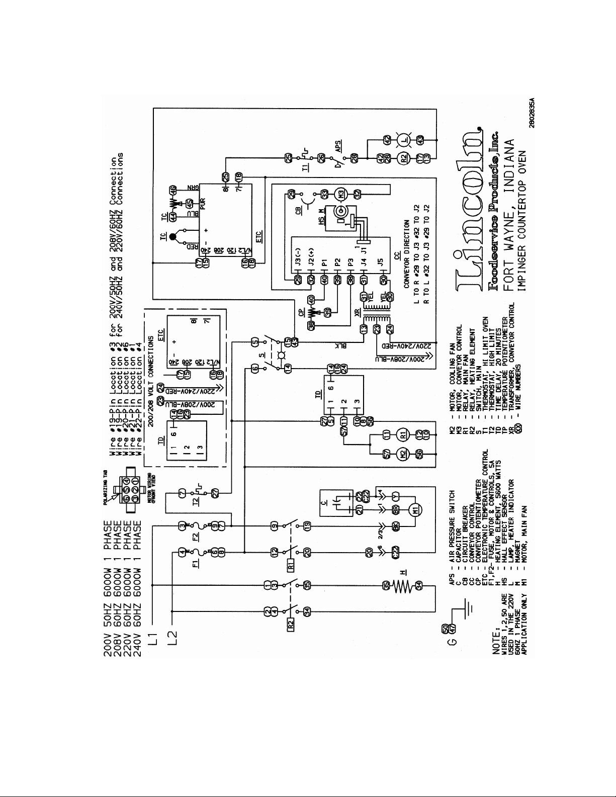
SCHEMATIC 1300, 1301, 1301-4, 1302, 1302-4, 1310 S/N 3022634 TO 3043630
CounterTop – 1300 Series Service Manual
9
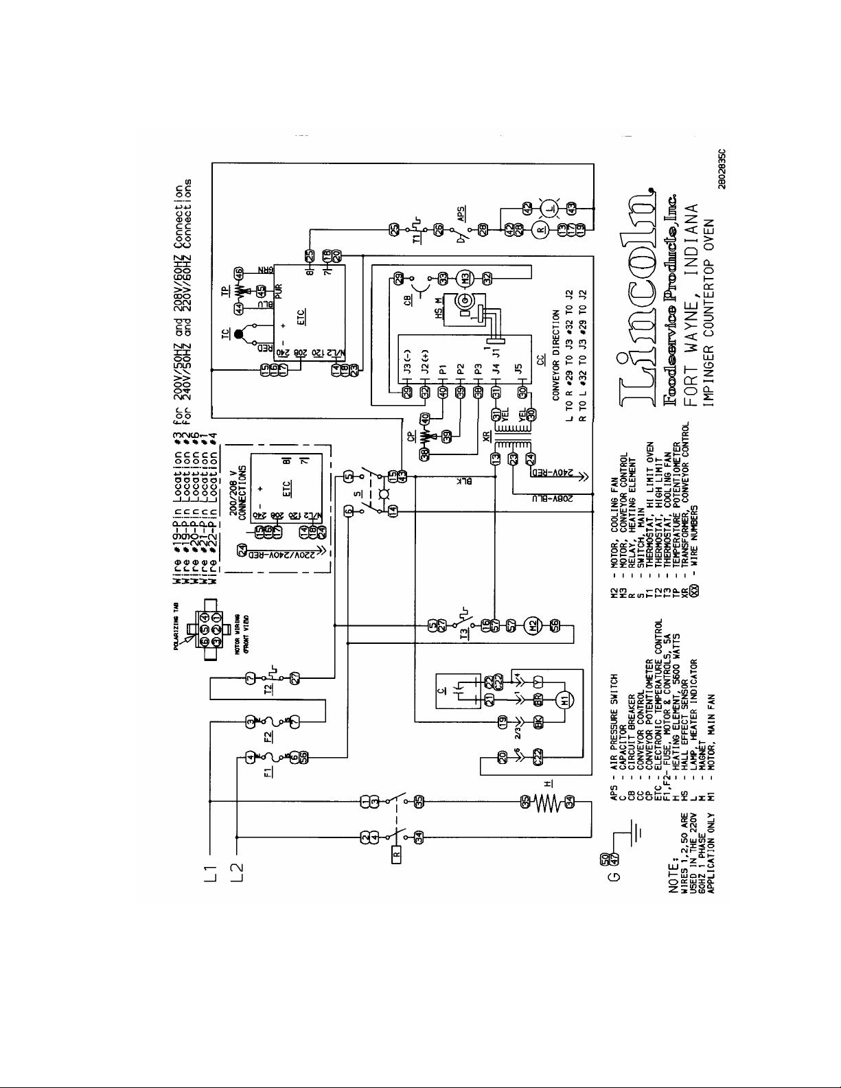
SCHEMATIC 1300, 1301, 1301-4, 1302, 1302-4, 1310 S/N 3043631 & ABOVE
CounterTop – 1300 Series Service Manual
10
SCHEMATIC 1301-4, 1302-4 S/N 3018980 & BELOW
CounterTop – 1300 Series Service Manual
11
SCHEMATIC 1301-4, 1302-4 S/N 3018981 TO 3043630
CounterTop – 1300 Series Service Manual
12
SCHEMATIC 1301-4, 1302-4 S/N 3043631 & ABOVE
CounterTop – 1300 Series Service Manual
13
SCHEMATIC 1303,1304 S/N 3018980 & BELOW
CounterTop – 1300 Series Service Manual
14
SCHEMATIC 1303,1304 S/N 3018981 TO 3043630
CounterTop – 1300 Series Service Manual
15
SCHEMATIC 1303,1304 S/N 3043631 & ABOVE
CounterTop – 1300 Series Service Manual
16
SCHEMATIC 1304-4 S/N 3018980 & BELOW
CounterTop – 1300 Series Service Manual
17
SCHEMATIC 1304-4 S/N 3018981 TO 3043630
CounterTop – 1300 Series Service Manual
18
SCHEMATIC 1304-4 S/N 3043631 & ABOVE
CounterTop – 1300 Series Service Manual
19
SCHEMATIC 1305,1306 S/N 3018980 & BELOW
CounterTop – 1300 Series Service Manual
20

SCHEMATIC 1305,1306 S/N 3018981 TO 3043630
CounterTop – 1300 Series Service Manual
21

SCHEMATIC 1305,1306 S/N 3043631 & ABOVE
CounterTop – 1300 Series Service Manual
22

SCHEMATIC 1305-4 S/N 3018980 & BELOW
CounterTop – 1300 Series Service Manual
23

SCHEMATIC 1305-4 S/N 3018981 TO 3043630
CounterTop – 1300 Series Service Manual
24

SCHEMATIC 1305-4 S/N 3043631 & ABOVE
CounterTop – 1300 Series Service Manual
25

SCHEMATIC 1307 S/N 3018980 & BELOW
CounterTop – 1300 Series Service Manual
26

SCHEMATIC 1307 S/N 3018981 TO 3043630
CounterTop – 1300 Series Service Manual
27

SCHEMATIC 1307 S/N 3043631 & ABOVE
CounterTop – 1300 Series Service Manual
28

SCHEMATIC 1308,1309,1311 S/N 3018980 & BELOW
CounterTop – 1300 Series Service Manual
29

SCHEMATIC 1308,1309,1311 S/N 3018981 TO 3043630
CounterTop – 1300 Series Service Manual
30

SCHEMATIC 1308,1309,1311 S/N 3043631 & ABOVE
CounterTop – 1300 Series Service Manual
31

SCHEMATIC 1308-4 S/N 3018980 & BELOW
CounterTop – 1300 Series Service Manual
32

SCHEMATIC 1308-4 S/N 3018981 TO 3043630
CounterTop – 1300 Series Service Manual
33

SCHEMATIC 1308-4 S/N 3043631 & ABOVE
CounterTop – 1300 Series Service Manual
34

SCHEMATIC 1312-000-E S/N 3018980 & BELOW
CounterTop – 1300 Series Service Manual
35

SCHEMATIC 1312-000-E S/N 3018981 & ABOVE
CounterTop – 1300 Series Service Manual
36

SCHEMATIC 1313-000-E S/N 3018980 & BELOW
CounterTop – 1300 Series Service Manual
37

SCHEMATIC 1313-000-E S/N 3018981 & ABOVE
CounterTop – 1300 Series Service Manual
38

SCHEMATIC 1314-F24-E S/N 3018980 & BELOW
CounterTop – 1300 Series Service Manual
39

SCHEMATIC 1314-F24-E S/N 3018981 & ABOVE
CounterTop – 1300 Series Service Manual
40

TROUBLESHOOTING GUIDE
IMPINGER CTI
SYMPTOM POSSIBLE CAUSE EVALUATION
Oven fan will not run
No main fan cool
down
Main fan continues to
run after cool down
No control box
cooling
Incoming Power Supply Check breakers, reset if required Check power plug
to be sure it is firmly in the receptacle (if applicable).
Measure the incoming power, call Power Co., if
needed
Oven Fan Fuses, 5 Amp Check and/or replace
Fuse Holder Check and/or replace
High Limit Thermostat
Control Box (Note: High
Limit not used in ovens
S/N 3000352)
Fan Switch Check continuity between switch terminals. Check
20 Minute Time Delay Check for supply voltage at terminal #1 to ground on
Main Fan Relay Check continuity of coil. Check for power to relay
Fan Motor Check for opens, shorts, or grounds. WITH POWER
Capacitor Check for opens, shorts, or grounds. WARNING
20-Minute Timer Check for supply voltage at terminal #2 and #3 while
20 Minute Timer NOTE: On/Off operation of fan switch will reset timer
Fan Switch WITH POWER OFF: Close switch and check for
20 Minute Timer See "Main Fan Motor will not run."
Cooling Fan Check for voltages at the fan motor, if present,
Check for voltage on both sides of the switch.
Terminals are normally closed. If open, reset and
test oven for proper operation. If thermostat and
below.) will not hold and control box temperature is
not exceeding 140°F (60°C), replace thermostat.
and insure good wire connections
the 20-minute timer. If no voltage is present, trace
wiring back to power supply. If voltage is present at
terminal #1, check for supply voltage at terminal #2 to
ground. If no voltage is present, and the oven fan
switch is closed, replace the 20-minute timer.
coil. Visually check for contact pull in and contact
condition. Check for voltage across relay terminals.
OFF: Turn fan blade to check for locked rotor.
Capacitor has a stored charge, discharge before
testing.
main fan is running. Turn off fan switch and supply
voltage should continue to be present for 20 min. at
terminal #2. Replace as needed.
to 20 minutes. If timer is accidentally reset, turn off
main breaker to cancel. If voltage continues to be
present at terminals 2 and 3 after 20 minutes, verify
fan switch contacts have opened, replace timer as
needed.
continuity across switch terminals.
replace defective fan motor.
CounterTop – 1300 Series Service Manual
41

Oven will not heat
Main Oven Fan Check if main oven fan is working. If not, refer to
"Oven Fan Will Not Run".
Temperature Control
Board
Check for voltage input at the board. Turn the
temperature adjustment knob to the maximum
temperature position and check for voltage at the load
terminal. If present, and unit is not heating, refer to "Air
pressure switch" for next check. If no voltage is
present, proceed.
Thermocouple Sensor Check terminals, wiring, and proper location of the
sensor bulb. It must be in its spring holder located in
the inside, rear, lower right hand corner (viewed from
front) behind Finger #4. The thermocouple is a type J
and has one red lead (Neg.) and one white lead
(Pos.).WITH POWER ON AND THERMOCOUPLE
LEADS ATTACHED TO THE TEMPERATURE
CONTROL BOARD: Measure the D.C. millivolt output
of these leads. Refer to thermocouple chart in Section
D for proper readings. If these readings are not
achieved, replace the thermocouple.
Temperature Set
Potentiometer
Disconnect the potentiometer leads from the board.
Place ohm meter test leads on the blue and green pot.
leads. Reading should be 1 K ohms. Place meter leads
across the blue and purple pot. leads and rotate knob
from high to low. Repeat on green and purple leads.
Check for even rise and fall of ohms reading to insure
that there are no open or dead spots in the
potentiometer. Check each lead to ground for shorts.
Replace Pot. if it does not meet the above test.
Hi Limit ThermostatOven Cavity
Terminals are normally closed, open at 660°F (350°C).
If open, push in reset button and retest. If thermostat
will not hold for maximum oven temperature, and oven
is not exceeding temperature dial setting, check for
proper location of capillary bulb in its spring holder. If
above checks okay, replace hi-limit thermostat.
Air Pressure Switch
(S/N 3043630 and
below)
Check for voltage on both sides of the switch, if voltage
is present on one side only, check for air tube
blockage, adjust air switch, if above fails, replace
switch.
Heating Element Relay Check for voltage to the Relay coil and contacts. If
voltage is present and contactor will not activate,
replace the contactor. Check for voltage across relay
terminals.
Heater Element Check the amperage draw on each hot leg for proper
load. Check the rating plate for rating information. If
amp draw is low or high, check element for opens and
shorts.
CounterTop – 1300 Series Service Manual
42

Conveyor will not run
S/N 3000480 and Below
Conveyor speed
varying or intermittent
Fan Switch Check continuity between switch terminals. Replace
as needed.
Conveyor Control
Transformer
Check for supply voltage at primary of transformer. If
no voltage is present, trace wiring back to fan switch.
Check for 24VAC at transformer secondary. If no
voltage is present, replace transformer.
Speed Adjustment
Potentiometer
This is a 5K ohm potentiometer. WITH POWER OFF:
Remove the leads from the motor control board at
terminals P1, P2, P3. With a digital meter, check the
ohm reading across the red and black leads. This
reading should be 5K ohms (± 10%) as the pot. is
rotated from low to high. Place meter leads on red
and white lead. Rotating the pot. slowly from low to
high, the meter reading should show an even
transition from 0 to 5K ohms (± 10%). There should
be no dead or open spots throughout the rotation of
the pot. Check all three (3) leads to ground. There
should be no continuity to ground. If any of the above
checks fail, replace the pot.
Conveyor Control Board Check for 24 VAC input to conveyor control. If no
voltage is present, trace wiring back to transformer. If
voltage is present at L1 and L2, check for D.C. output
at terminals A+ and A-. If there is AC voltage input,
but no D.C. voltage output, replace conveyor control
board.
Conveyor Gear Motor If there is D.C. voltage output from the conveyor
control, but the motor does not run, check the mini-
breaker (0.7 Amp). Check motor leads for opens,
shorts or continuity to ground. If motor fails above
test, replace motor.
Conveyor Check conveyor drive coupling to be sure that it is
tight. Also check to see that coupling is engaged with
conveyor drive shaft. Check for any mechanical
misalignment or improper adjustment, also check for
worn bearings. A conveyor belt that is too tight will
cause excessive bearing wear and sometimes-
irregular speed.
Power Supply Check for steady supply voltage to oven. If voltage is
unsteady, contact power company.
Transformer Check for steady A.C. voltage output from transformer
and replace as needed.
Conveyor Control Check for steady D.C. voltage output from conveyor
control. If D.C. voltage output is unsteady, check
conveyor potentiometer (see "Speed Adjustment
Potentiometer" under Conveyor will not run). If the
potentiometer checks good, and the D.C. voltage is
unsteady, replace conveyor control.
D.C. Gearmotor Chec k motor brushes for excessive arching and/or
unusual wear. Replace brushes or gearmotor as
needed.
CounterTop – 1300 Series Service Manual
43

Conveyor will not run
(S/N 3000481 & Above)
Conveyor speed
varying or intermittent
Fan Switch WITH POWER OFF: Check continuity between switch
terminals. Check and insure good wire connections.
Conveyor Control
Transformer
With the fan switch on, check for supply voltage at the
primary of the transformer. Check for voltage on the
secondary side of transformer (24 VAC) at J4 and J5 on
the conveyor control board. Replace as needed.
Speed Adjustment Pot This is a 50 K ohm potentiometer. WITH POWER OFF:
Remove the leads from the motor control board at
terminals P1, P2, P3. With a digital meter, check the
ohm reading across the red and black leads. This
reading should be 50K ohms (± 10%) as the pot. is
rotated from low to high. Place meter leads on red and
white lead. Rotating the pot. slowly from low to high, the
meter reading should show an even transition from 0 to
50 K ohms (±10%). There should be no dead or opens
spots throughout the rotation of the pot. Check all three
(3) leads to ground. There should be no continuity to
ground. If any of the above checks fail, replace the pot.
Conveyor Control
Board
Check for 24 VAC input to the control board at terminals
J4 and J5. If not present, check wiring back to control
transformer, if voltage is present at J4 and J5, check the
VDC output at terminals J2 (+) & J3 (-) (0-18 VDC). If
24 VAC is present at J4 and J5, but VDC is not present
at J2(+) & J3(-) replace board.
Conveyor Gear Motor If D.C. voltage is present at J2(+) and J3(-) and the
motor does not run, first check the mini breaker (.7Amp).
Check the leads to the motor for evidence of any shorts
or opens, and each lead to ground. If the motor fails the
above tests, replace motor.
Conveyor Check for any mechanical misalignment or improper
adjustment, also check for worn bearings. A conveyor
belt that is too tight will cause excessive bearing wear
and sometimes, irregular speed.
Power Supply Check for steady supply voltage to oven. If voltage is
unsteady, contact Power Company.
Transformer Check for steady AC voltage output from transformer
and replace as needed.
Conveyor Control Check for steady D.C. voltage output from conveyor
control. If D.C. voltage output is unsteady, check
conveyor potentiometer (See Speed Adjustment
Potentiometer" under Conveyor will not run). If the
potentiometer checks good, and the D.C. voltage is
unsteady, replace conveyor control.
D.C. Gearmotor Check motor brushes for excessive arching and/or
unusual wear. Replace brushes or gearmotor as
needed
Magnet Check to insure that the magnet (cemented to shaft of
conveyor drive motor) has not been damaged, or come
loose from motor shaft. Replace as needed.
Hall Effect Sensor Check for any physical damage to Hall Effect Sensor
(mounted on conveyor motor). Check all wiring and
connections or damage. Check all connections for
tightness or proper location and check all wiring or
visible damage. Replace as needed.
CounterTop – 1300 Series Service Manual
44

REMOVAL, INSTALLATION, AND ADJUSTMENT
MODEL SERIES 1300
CAUTION!
BEFORE REMOVING OR INSTALLING ANY COMPONENT IN THE IMPINGER
OVEN BE SURE TO DISCONNECT ELECTRICAL POWER SUPPLY
SWITCH, ON-OFF
1. Remove conveyor and oven side panels.
2. Remove two (2) screws from ends of control panel and remove panel.
3. Disconnect four (4) wires from switch assembly. Mark wires for reinstallation.
4. Depress clips on side of switch and remove from panel.
5. Reassemble in reverse order and check operation.
POTENTIOMETER, CONVEYOR CONTROL
1. Remove conveyor and oven side panels.
2. Remove two (2) screws from ends of control panel and remove panel.
3. Unplug potentiometer at the wire harness (push on connectors).
4. Loosen set screws on control knob and remove knob.
5. Remove retaining nut from potentiometer shaft and remove pot.
6. Reassemble in reverse order and check operation, recalibrate if needed.
POTENTIOMETER, TEMPERATURE CONTROL
1. Remove conveyor and oven side panels.
2. Remove two (2) screws from ends of control panel and remove panel.
3. Unplug potentiometer at the wire harness (push on connectors).
4. Loosen set screws on control knob and remove knob.
5. Remove retaining nut from potentiometer shaft and remove pot.
6. Reassemble in reverse order and check operation, recalibrate if needed.
CIRCUIT BREAKER, 0.7 AMP
1. Remove control box cover.
2. Remove two (2) wires from mini-breaker.
3. Remove knurled nut and remove breaker.
4. Reassemble in reverse order and check operation.
FUSE HOLDER
1. Remove control box cover.
2. Remove two (2) wires from fuse holder.
3. Remove two (2) screws and remove holder.
4. Reassemble in reverse order and check operation.
CounterTop – 1300 Series Service Manual
45

THERMOSTAT, OVEN CAVITY HI-LIMIT
1. Remove control box cover.
2. Remove oven back assembly. (See OVEN BACK)
3. Remove two (2) wires from thermostat.
4. Remove retaining nut from the front of thermostat and remove thermostat.
5. Remove capillary tube from wire form in back of oven and remove assembly out through control box side.
6. Reassemble in reverse order. Check for proper routing through insulation. Be sure capillary tube is held
securely in the wire form and the reset button has been pushed in and set.
NOTE: All excess capillary tubing should be brought back into control box area. Be certain to replace
insulation seal when oven back is re-installed.
7. Check operation.
AIR PRESSURE SWITCH – REPLACEMENT (S/N 3043630 and below)
1. Remove control box cover.
2. Remove two (2) wires.
3. Remove air tube (note location).
4. Remove four (4) screws and replace air switch.
5. Reassemble in reverse order and check operation.
NOTE: Make sure to use rubber grommets when installing air switch.
ADJUSTMENT SCREW
AIR PRESSURE SWITCH – ADJUSTMENT (S/N 3043630 and below)
1. Apply power to oven, turn temperature control potentiometer to max. and allow 30-minutes preheat for
temperatures to stabilize.
2. Remove air tube and with a volt meter verify that contactor for heater elements opens.
3. WITH POWER ON: Re-connect tube and check voltage across the air switch making sure that there is
no voltage drop and it remains steady. Adjust as needed. (See Picture, verify adjustment screw has not
vibrated out).
NOTE: Allow 30 minutes preheat.
THERMOSTAT, CONTROL BOX HI-LIMIT
1. Remove control box cover.
2. Remove two (2) wires.
3. Remove two (2) screws and replace
4. Reassemble in reverse order and check operation.
NOTE: Make sure reset button has been pushed and set.
CounterTop – 1300 Series Service Manual
46

MAIN FAN RELAY
1. Remove control box cover
2. Remove wires from relay and mark wires for reinstallation.
3. Remove two (2) screws and replace relay.
4. Reassemble in reverse order and check operation.
TIME DELAY RELAY
1. Remove control box cover.
2. Remove wires from relay and mark wires for reinstallation. CAUTION: Resistor should be jumpered
across terminals #2 and #3 on some of the early models (SN 3000352 and belo w) this ju mper was
installed across terminals #1 and #3 which may cause failure of the timer. Correct when replacin g
timer.
3. Remove screw and replace relay.
4. Reassemble in reverse order and check operation.
NOTE: Do not overtighten mounting screw as this could damage timer.
RELAY CONTACTOR
1. Remove control box cover.
2. Remove wires and mark wires for reinstallation.
3. Remove four (4) mounting screws and replace contactor.
4. Reassemble in reverse order and check operation.
TRANSFORMER - CONVEYOR
1. Remove control box cover.
2. Disconnect wires from primary and secondary of transformer. Mark wires for reinstallation (#23-blue208V connection/#24-red-240V connection).
NOTE: Wire nut one not being used.
3. Remove two (2) mounting screws and replace.
4. Reassemble in reverse order and check operation.
CONVEYOR DRIVE MOTOR
1. Remove conveyor (see Installation and Operations Manual).
2. Remove screw from center of coupling sleeve assemby. and slide coupling assembly off motor shaft.
3. Remove control box cover.
4. Disconnect motor leads and mark wires for reinstallation and conveyor direction.
5. Remove four (4) motor mounting screws and replace motor.
6. Reassemble in reverse order and check operation.
NOTE: Check to insure coupling and conveyor shaft are aligned.
NOTE: Starting with SN 3000481 all conveyor drives will be a closed loop system. The drive motor
assembly will include a hall effect sensor board and magnet. No calibration req uired.
S/N 3000480 and Below--Check calibration of conveyor control board (See "Conveyor control board
calibration")
S/N 3000481 and Above--Attach correct magnet to conveyor motor assembly.
CounterTop – 1300 Series Service Manual
47

ASSEMBLY OF MAGNET TO MOTOR
FOR OVENS WITH 1-12 MINUTE CONVEYOR DRIVE SYSTEM
1. Apply 1 or 2 drops of adhesive (supplied) to magnet. Mount magnet on motor shaft. Be sure to keep
adhesive away from motor bearings.
NOTE: Use magnet marked "8"
FOR OVENS WITH 1-24 MINUTE CONVEYOR DRIVE SYSTEM
1. Apply 1 or 2 drops of adhesive (supplied) to magnet. Mount magnet on motor shaft. Be sure to keep
adhesive away from motor bearing.
NOTE: Use magnet marked "16"
CONVEYOR CONTROL BOARD - REPLACEMENT
1. Remove control box cover.
2. Disconnect and mark all wires from the control board.
3. Remove two (2) screws from mounting bracket at rear wall and remove assembly.
4. Depress nylon clips and remove circuit board from mounting bracket.
5. Reassemble in reverse order and check operation.
CONVEYOR CONTROL BOARD CALIBRATION (S/N 3000480 AND BELOW)
(NOTE: S/N 3000481 & ABOVE, NO CALIBRATION REQUIRED)
1. Remove control box cover.
2. Connect digital meter to A+ & A-.
3. With conveyor running at maximum speed, adjust max pot on board to 21.5 to 22 VDC.
4. With conveyor running at minimum speed, adjust min pot on board to 3 to 4 VDC.
5. Check conveyor belt timing (leading edge in to leading edge out) at 5 min. and adjust, potentiometer
knob if necessary to compensate (S/N 3000481 & above, no calibration required).
ELECTRONIC TEMPERATURE CONTROL BOARD - REPLACE M ENT
1. Remove control box cover.
2. Disconnect wires and molded connector and mark wires for reinstallation.
3. Remove two (2) screws from mounting bracket and remove assembly.
4. Depress nylon clips and remove circuit board from mounting bracket.
5. Reassemble in reverse order and check operation.
ELECTRONIC TEMPERATURE CONTROL - CALIBRATION
1. Turn oven on, allow 30 minutes preheat for temperatures to stabilize in oven cavity.
2. Remove control box cover.
3. Place temperature probe in bottom
rear
.
finger #4 (lower right), 3rd row from outside edge, 3rd hole from the
NOTE: Make sure probe is not touching any metal surfaces. (Measure air temperature only)
4. Turn temperature control knob fully clockwise and adjust so the knob indicator is aligned with the mark
past
550°F (288°C) on the dial. (See diagram Pg. 13)
CounterTop – 1300 Series Service Manual
48

177C/350F 240C/400F
149C/300F
121C/250F
93C/200F
550F/288C
CALIBRATION MARK
450F/232C
500F/260C
5. Turn the temperature control knob to 500°F (260°C) and calibrate the tempe rature control board. Adjust the
potentiometer only (see diagram Pg. D5) so the unit cycles at 500°F ± 10°F (490°F - 510°F).
top
6. Turn the temperature control knob to 550°F and verify that the oven will cycle at 550°F (288°C) ± 10°F.
7. Replace the control box cover and check operation.
CONTROL BOX
TEMPERATURE
CONTROL BOARD
HI-LIMIT
AIR SWITCH
TRANSFORMER
CONVEYOR
DRIVE MOTOR
CounterTop – 1300 Series Service Manual
49

COOLING FAN, CONTROL BOX
1. Remove control box cover.
2. Remove four (4) screws.
3. Lift off fan guard and finger guard.
4. Disconnect two wires and replace fan.
5. Reassemble in reverse order and check operation.
NOTE: Check to insure that control box high limit switch is not tripped. Reset if needed.
CAPACITOR, MOTOR
1. Remove six (6) acorn nuts from motor cover and remove.
CAUTION: DISCHARGE CAPACITOR BEFORE REMOVING.
2. Remove wires from capacitor and mark wires for reinstallation.
3. Loosen clamp around capacitor and remove.
4. Reinstall in reverse order and check operation.
OVEN BACK ASSEMBLY
1. Remove six (6) acorn nuts and remove motor cover.
2. Disconnect all wiring from motor and heating element.
3. Remove four (4) nuts holding oven back and remove oven back.
4. Reassemble in reverse order. NOTE: Be certain to replace insulation seal each time oven back is
removed.
MAIN FAN
1. Remove six (6) acorn nuts holding motor cover and remove.
2. Remove four (4) acorn nuts holding oven back assembly and remove.
3. Loosen two (2) screws on fan hub and slide fan off of motor shaft. (Note location of hub on motor shaft
for reinstallation. Approximately 3/16" from back wall.)
4. Reinstall in reverse order and check system operation. Allow 30 minute preheat and verify that fan is not
rubbing.
NOTE: Be certain to replace insulation seal each time oven back is removed.
CounterTop – 1300 Series Service Manual
50

THERMOCOUPLE
1. Remove control box cover.
2. Remove six (6) acorn nuts holding motor cover and remove.
3. Remove four (4) acorn nuts holding oven back assembly and remove oven back.
4. Remove thermocouple bulb from wire form in rear of oven cavity.
5. Disconnect and mark wires from temperature control board (red=neg., white=pos.) and remove
thermocouple.
6. Reassemble in reverse order and check operation. NOTE: Be certain to replace insulation seal each
time oven back is removed.
INFORMATION:
When two wires composed of dissimilar metals are joined together and one of the ends is heated, a
continuous current flow is generated. We use an iron constant (Type J) thermocouple. The iron wire
increases the number of dissimilar junctions in the circuit.
It is possible to check a thermocouple with a properly calibrated D.C. millivolt meter. At 32°F, the
millivolt reading should be 0.00. This can be checked by inserting the thermocouple into an ice bath.
The millivolt reading at 72°F should be 1.134.
When using the following chart, the temperature at the terminal connections must be noted. This
temperature is called the Junction Temperature.
The following chart lists the thermocouple millivolt readings from 200°F to 600°F.
O V E N T E M P E R A T U R E
J U N C T I O N T E M P E R A T U R E
200°F 250°F 300°F 325°F 350°F 400°F 425°F 450°F 500°F 550°F 600°F
90°F 3.26 4.77 6.30 7.06 7.83 9.37 10.14 10.91 12.46 14.00 15.53
88°F 3.32 4.83 6.36 7.12 7.89 9.43 10.20 10.97 12.51 14.05 15.59
86°F 3.37 4.88 6.41 7.17 7.94 9.49 10.26 11.03 12.57 14.11 15.65
84°F 3.43 4.94 6.47 7.23 8.00 9.54 10.31 11.09 12.63 14.19 15.71
82°F 3.49 5.00 6.53 7.29 8.06 9.60 10.37 11.14 12.69 14.23 15.76
80°F 3.55 5.06 6.59 7.35 8.12 9.66 10.43 11.20 12.74 14.28 15.82
78°F 3.60 5.11 6.64 7.40 8.17 9.72 10.49 11.26 12.80 14.34 15.86
76°F 3.66 5.17 6.70 7.46 8.23 9.77 10.55 11.32 12.86 14.40 15.94
75°F 3.69 5.20 6.73 7.49 5.26 9.80 10.57 11.35 12.89 14.43 15.97
74°F 3.72 5.23 6.76 7.52 8.29 9.83 10.60 11.37 12.92 14.46 15.99
72°F 3.78 5.29 6.82 7.58 8.35 9.89 10.66 11.43 12.97 14.51 16.05
70°F 3.83 5.34 6.87 7.63 8.40 9.95 10.72 11.49 13.03 14.57 16.11
68°F 3.89 5.40 6.93 7.69 8.46 10.00 10.78 11.55 13.09 14.63 16.17
66°F 3.95 5.46 6.99 7.75 8.52 10.06 10.83 11.61 13.15 14.69 16.23
64°F 4.01 5.52 7.05 7.81 8.58 10.12 10.89 11.66 13.20 14.74 16.28
62°F 4.06 5.57 7.10 7.86 8.63 10.18 10.95 11.72 13.26 14.80 16.34
60°F 4.12 5.63 7.16 7.92 8.69 10.24 11.01 11.78 13.32 14.86 16.40
CounterTop – 1300 Series Service Manual
51

HEATING ELEMENT (Color Coded on the Cold Zone)
PART# 369418
PART# 369419
PART# 369450
PART# 369455
PART# 369456
PART# 369457
PART# 369475
PART# 369476
PART# 369477
PART# 370104
PART# 370105
Heating Element 208V Red
Heating Element 240V Blue
Heating Element 220V Yellow
Heating Element 200V Orange
Heating Element 380V Violet
Heating Element 415V Green
Heating Element 200V 3 PH Orange
Heating Element 380V 3 PH Violet
Heating Element 415V 3 PH Green
Heating Element 400V 3 PH Brown
Heating Element 400V 1 PH Brown
1. Remove six (6) acorn nuts holding motor cover and remove
2. Remove connectors from element.
3. Remove four (4) acorn nuts holding oven back assembly and remove.
4. Remove three (3) screws from heating element brackets and slide element out of back assembly.
5. Reassemble in reverse order. Verify by color code, dot or band on element that correct element is being
installed. Refer to chart above:
NOTE: Be certain to replace insulation seal each time oven back is removed.
AIR PUMP
1. Remove six (6) acorn nuts holding motor cover and remove.
2. Disconnect motor, capacitor, and element leads and mark wires for reinstallation.
3. Remove four (4) acorn nuts holding oven back assembly and remove.
4. Remove main fan. (Note location, approximately 3/16" from back wall on motor shaft.)
5. Remove heating element.
6. Remove five (5) screws from inner back assembly and lift off.
7. Loosen two screws on air pump hub and slide off shaft. (Note location for reinstallation (approximately
3/64" clearance from back wall).
8. Reinstall in reverse order and check operation. Allow 30 minute preheat and verify that fan is not
rubbing.
NOTE: Be certain to replace insulation seal each time oven back is removed.
MAIN FAN MOTOR
1. Remove six (6) acorn nuts holding motor cover and remove.
2. Disconnect motor, capacitor, and heating element and mark wires for reassembly.
3. Remove four (4) acorn nuts holding oven back assembly and remove.
4. Remove heating element (See "heating element removal").
5. Remove main fan, NOTE position ("See fan removal").
6. Remove five (5) screws from inner back and separate.
7. Remove air pump assembly
NOTE location.
8. Remove four (4) screws from motor mount pedestal and lift motor and pedestal off outer back assembly.
9. Remove four (4) nuts from front motor studs and remove mounting pedestal.
10. Reassemble in reverse order and check operation.
NOTE: Be certain to replace insulation seal each time oven back is removed
CounterTop – 1300 Series Service Manual
52

This page intentionally left blank.
CounterTop – 1300 Series Service Manual
53

GENERAL – 1300 SERIES
LETTER P/N DESCRIPTION
A 369434 Air Duct Panel, Upper
B 369442 Finger Housing S/N 3002167 & Below
C 369436 Columnating Plate #2 (UR) – S/N 3002167 & Below
D 369445 Finger Cover, Upper Right – S/N 3002167 & Below
E 369441 Finger Cover, Lower Right – S/N 3002167 & Below
F 369439 Columnating Plate #4 (LR) – S/N 3002167 & Below
G 369435 Air Duct Panel, Lower
H 369438 Columnating Plate #3 (LL) – S/N 3002167 & Below
I 369444 Finger Cover, Lower Left – S/N 3002167 & Below
J 369446 Finger Cover, Upper Left – S/N 3002167 & Below
K 369437 Columnating Plate #1 (UL) – S/N 3002167 & Below
L 369916 Top / Front Cover Panel
M 369484 Cover Panel Assy
N 369407 Fastener & Split Ring Retainer (S/N 3046209 & Below)
369211 Thumb Screw (S/N 3046210 & Above)
O 369447 Cover Panel Assembly, Right
P 369953 Flat Washer, S/S
Q 369460 Compression Spring
R 369410 Coupling Sleeve
S 370106 Flat Washer, .156 x .430
T 350259 Screw, THMS 6-32 x 3/8
U 369413 Drive Key
V 369373 Receptacle, Snap-In
W 369461 Leg, 4”
X 369945 Control Panel
Y 369429 Knob, Control
Z 369432 Switch, On – Off
AA 369449 Temperature Control Pot. Assembly
BB 369433 Potentiometer Control, Conveyor S/N 3000480 & Below
369468 Potentiometer Control, Conveyor S/N 3000481 & Above
CC 350224 Lens, Yellow
DD 369448 Cover Panel Assembly, Left
EE 369467 Pilot Light & Harness – S/N 3000481 & Above
FF 369495 Conveyor Baffle
GG 369211 Thumb Screw
HH 369451 Mounting Ring Assy.
JJ 369491 Finger Cover – S/N 3002168 & Above (4 required)
KK 369490 Columnating Plate – S/n 3002168 & Above (4 required)
LL 369488 Finger housing – S/n 3002168 & Above (4 required)
MM 369932 Facia 1-12 Minute Bake Time
370096 Facia 2-24 Minute Bake Time
370018 Facia 1-24 Minute Bake Time
NN 370095 Control Guard
OO 370097 Screw 10-32 x ¼”
PP 370657 Finger Cover (S/N 3045308 & Above)
QQ 370658 Columnating Plate (S/N 3045308 & Above)
RR 369442 Finger Housing (S/N 3045308 & Above)
SS 370656 Lower Air Duct Panel (S/N 3045308 & Above)
TT 370655 Upper Air Duct Panel (S/N 3045308 & Above)
CounterTop – 1300 Series Service Manual
54

GENERAL – 1300 SERIES PARTS BLOW-UP
NEW FINGER ASSEMBLY (S/N 3045308 & ABOVE)
PP
QQ
RR
TT
CounterTop – 1300 Series Service Manual
55

CONTROL COMPARTMENT – 1300 SERIES
LETTER P/N DESCRIPTION
A 369426 Cooling Fan – S/N 3000399 & Below
369378 Cooling Fan – S/N 3000400 & Above
B 369428 Finger Guard – S/N 3000399 & Below
369331 Finger Guard – S/N 3000400 & Above
C 369415 Conveyor Control S/N 3000480 & Below
369464 Conveyor Control – S/N 3000481 to 3007663
Except Models 1301-5, 1302-5, 1304-5, 1308-5
370017 Conveyor Control S/N 3007664 and Above and
All S/N for Models 1301-5, 1302-5, 1304-5, 1308-5
D 369431 Thermostat, Control Box Hi-Limit S/n 3000352 & Above
E 369430 Air Switch – S/N 3043630 & Below
F 369422 Relay SPST, 240V
G 369417 Time Delay Relay
H 369425 Relay Contactor Single Phase
369479 Relay Contactor 3 Pole 3 Phase
I 369427 Transformer, Conveyor Control
370241 Transformer, Conveyor Control Models 1312,1313,1314
J 369416 Electronic Temperature Control S/N 3000480 & Below
369465 Electronic Temperature Control S/N 3000481 & Above
K 369129 Fuse Holder, Model 1300,1301,1302,1307
L 369424 Conveyor Drive Motor S/N 3000480 & Below
369923 Conveyor Motor Assy. Models 1301-5,1302-5,1304-5,1308-5
369466 Conveyor Motor Assy (Assy. Includes Q,R)
S/N 3000481 & Above Except 1301-5,1302-5,1304-5,1308-5
369841 Brushes (For 369466 Motor)
M 369154 Circuit Breaker - .7Amp
N
O 369483 Housing Assy.
P 369482 Fan Housing
Q 369822 Magnet, 8 Pole (For 1-12 Minute Conveyor System)
370065 Magnet, 16 Pole (For 1-24 Minute Conveyor System)
R 369823 Hall Effect Sensor
S 369421 Fuse 5A, Model 1300,1301,1302,1307
T 370100 Conveyor Motor Plate, Inner
U 370040 Hall Effect Cable
V 370099 Conveyor Motor Plate, Outer
W 369414 Power Cord 30A S/n 3007818 & Below (Model 1301,1302)
370019 Power Cord 50A S/N 3007819 & Above (Model 1301,1302)
X 369536 Cooling Fan Cordset
Y 369085 Junction Box
Z 369376 Terminal Block 3 Pole
369584 Terminal Block 4 Pole
AA 369698 Cover, Junction Box
BB 369856 Stand-off, Support
CC 357107 Fuseholder
DD 369492 Fuse 5A
EE 369131 Thermocouple
357067 Thermostat, Capillary
4030184 Thermostat, Capillary (CE models)
CounterTop – 1300 Series Service Manual
56

CONTROL COMPARTMENT – 1300 SERIES BLOW - UP
CounterTop – 1300 Series Service Manual
57

BACK – 1300 SERIES
LETTER P/N DESCRIPTION
Color Coded on The Cold Zone
A 369418 Heating Element - 208V Red
369419 Heating Element - 240V Blue
369450 Heating Element - 220V Yellow
369455 Heating Element - 200V Orange
369456 Heating Element - 380V Violet
370105 Heating Element - 400V 1 PH Brown
369457 Heating Element - 415V Green
369475 Heating Element - 200V 3 PH Orange
369476 Heating Element - 380V 3 PH Violet
370104 Heating Element - 400V 3 PH Brown
369477 Heating Element - 415V 3 PH Green
B 369409 Main Fan
C 369408 Air Pump
D 369440 Nut, S/S ¼ - 20
E 369192 Capacitor
F 369458 Nut, 10-32
G 370041 Duct Assy
H 370020 Motor Cover Assy
I 370102 Bottom Cap, Flue Duct
J 369453 Flue Duct Assembly
K 369423 Motor, Main Fan S/N 3002137 & Below – All 1301-4,1302-4
369485 Motor, Main Fan 60 Hz S/N 3002168 & Above
370179 Motor, Main Fan 50 Hz – Models 1304-4,1305-4,1308-4
369480 Motor, Main Fan 50 Hz S/n 3002168 & Above
L 369940 Motor Mount
M 370093 Motor Plate Assy
N 369474 Insulation, Air Pump Panel
O 369936 Plenum Barrier Panel
P 369473 Insulation, Plenum Panel
Q
R 369470 Insulation Seal
S 369497 Bracket, Thermostat, Left Side
T 369496 Bracket, Thermostat, Right Side
U 369459 Motor Cover Assy
369935 Cover Plate, Plenum
370728 Cover Plate, Plenum (F or CE Units Only)
CounterTop – 1300 Series Service Manual
58

BACK – 1300 SERIES BLOW - UP
CounterTop – 1300 Series Service Manual
59

STANDARD CONVEYOR – 1300 SERIES
LETTER P/N DESCRIPTION
369443 Standard Complete Conveyor Assy. (31” Length)
A 369462 Idler Axle
B 369515 Drive Sprocket
C 369516 Conveyor Bearing
D 369463 Drive Axle
E 369471 Roll Pin, 5/32 x 7/8”
F 1343 Entry Shelf – 12”
1344 Entry Shelf – 4”
G 369412 Conveyor Splice Clip
H 369411 Conveyor Belting
370185 Conveyor Belting (1 foot section)
I 1341 Exit Shelf – 12”
1342 Exit Shelf – 4”
J 370094 Conveyor Frame Assembly
CounterTop – 1300 Series Service Manual
60

EXTENDED CONVEYOR – 1300 SERIES
LETTER P/N DESCRIPTION
369909 Extended Conveyor Assy. (49 ¾” Length)
A 369462 Idler Axle
B 369515 Drive Sprocket
C 369516 Conveyor Bearing
D 369463 Drive Axle
E 369471 Roll Pin, 5/32 x 7/8”
F 369943 Conveyor Frame, Extended
G 369412 Conveyor Splice Clip
H 369481 Conveyor Belting – Extended Conveyor
370185 Conveyor Belting (1 Foot Section)
I 369920 Retainer
J 369921 Roller, Slider Bed
K 369954 Pop Rivet S/S
L 369922 Support Rod
M 1345 Pan Stop
N 369489 Crumb Pan Assembly
CounterTop – 1300 Series Service Manual
61

This page intentionally left blank.
CounterTop – 1300 Series Service Manual
62

This page intentionally left blank.
CounterTop – 1300 Series Service Manual
63

Lincoln Foodservice Products, LLC
1111 North Hadley Road
Fort Wayne, Indiana 46804
United States of America
Phone : (800) 374-3004
U.S. Fax: (888) 790-8193 • Int’l Fax: (260) 436-0735
Technical Service Hot Line
(800) 678-9511
www.lincolnfp.com
CounterTop – 1300 Series Service Manual
64
 Loading...