

Page 1
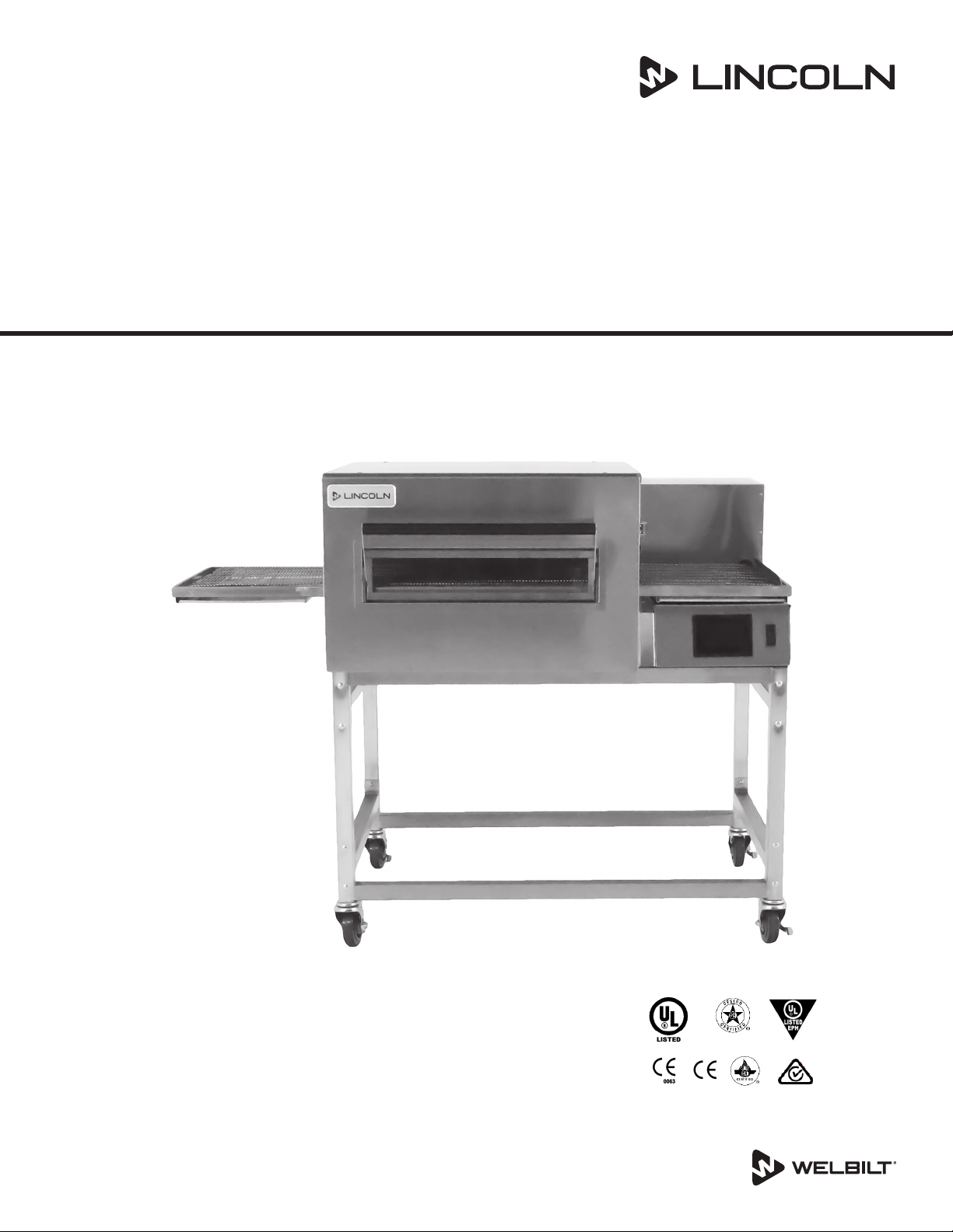
Impinger® II Conveyor Oven with
easyTouch Controls
Series 1100
Installation, Operation and Maintenance Manual
FOR 50 HZ AND 60 HZ SUPPLY
Original Instructions
Part Number 4607056 Rev 0 6/21
Page 2
Safety Notices
DEFINITIONS
DANGER
Indicates a hazardous situation that, if not avoided, will
result in death or serious injury. This applies to the most
extreme situations.
Warning
n
Indicates a hazardous situation that, if not avoided,
could result in death or serious injury.
Caution
,
Indicates a hazardous situation that, if not avoided,
could result in minor or moderate injury.
Notice
Indicates information considered important, but not
hazard-related (e.g. messages relating to property
damage).
NOTE: Indicates useful, extra information about the
procedure you are performing.
Read These Before Proceeding:
DANGER
Do not install or operate equipment that has been
misused, abused, neglected, damaged, or altered/
modified from that of original manufactured
specifications.
Important
Read these instructions for use carefully so as to
familiarize yourself with the appliance before connecting
it to its gas container. Keep these instrucions for future
reference.
Warning
n
Improper installation adjustment, alteration, service
or maintenance can cause property damage, injury or
death. Read the installation, operating and maintenance
instructions thoroughly before installing or servicing
this equipment.
Warning
n
Authorized Service Representatives are obligated to
follow industry standard safety procedures, including,
but not limited to, local/national regulations for
disconnection / lock out / tag out procedures for all
utilities including electric, gas, water and steam.
Warning
n
This appliance is not intended for use by persons
(including children) with reduced physical, sensory
or mental capabilities, or lack of experience and
knowledge, unless they have been given supervision
concerning use of the appliance by a person responsible
for their safety. Do not allow children to play with this
appliance.
Warning
n
This equipment is intended for indoor use only. Do not
install or operate this equipment in outdoor areas.
Warning
n
Do not use electrical appliances or accessories other
than those supplied by the manufacturer.
FOR YOUR SAFETY
Do Not Store Or Use Gasoline Or Other Flammable
Vapors Or Liquids In The Vicinity Of This Or Any Other
Appliance.
Warning
n
Never use a high-pressure water jet for cleaning or hose
down or flood interior or exterior of units with water. Do
not use power cleaning equipment, steel wool, scrapers
or wire brushes on stainless steel or painted surfaces.
Caution
,
Maintenance and servicing work other than cleaning as
described in this manual must be done by authorized
service personnel.
Caution
,
Improper cleaning of oven could damage catalyst(s) in
ventless models and will void unit warranty.
NOTE: Proper installation, care and maintenance are essential
for maximum performance and trouble-free operation of
your equipment. Visit our website www.wbtkitchencare.com
for manual updates, translations, or contact information for
service agents in your area.
Page 3

Safety Notices ..................................................................................................................... 2
Section 1
General Information
Purchaser’s Responsibility ................................................................................................. 5
Model Number Key ............................................................................................................6
Section 2
Installation
Exterior Dimensions...........................................................................................................7
Utility Specifications .......................................................................................................... 8
Canopy Ventilation Recommendations ............................................................................ 9
Utility Service Layout – Models 1116 & 1117 ................................................................. 10
Installation Requirements ...............................................................................................11
Installation ........................................................................................................................13
Assembly Instruction ....................................................................................................... 14
Stacking Instructions ....................................................................................................... 14
Start-Up Checkout ............................................................................................................ 16
Start-Up Procedures .........................................................................................................17
Installation Checklist .......................................................................................................17
Section 3
Operation and Programming
Table of Contents
Definitions.................................................................................................................................................2
Additional Requirements ....................................................................................................................5
Gas Code Requirements ................................................................................................................... 11
Electrical Code Requirements ......................................................................................................... 11
Spacing Requirements ...................................................................................................................... 12
Ventilation Requirements.................................................................................................................12
Restraint Requirement – Gas Oven(s) on Casters .................................................................... 13
Packing and Weights .......................................................................................................................... 13
Uncrating ................................................................................................................................................ 13
For Single Oven .................................................................................................................................... 14
For Double Oven ................................................................................................................................14
For Triple Oven ..................................................................................................................................... 15
Smoke Candle Test – Ventilation System Verification .............................................................17
Checklist ................................................................................................................................................. 18
Introduction ......................................................................................................................19
Startup ..............................................................................................................................19
Recipe Selection [Press & Go Button] ........................................................................................... 19
Manual Mode ........................................................................................................................................ 20
Changing Temperature and Cook Time [Belt Speed] ............................................................. 20
Settings Mode ...................................................................................................................................... 21
Diagnostics Mode ............................................................................................................................... 22
Oven Shut Down ................................................................................................................................. 22
Part Number 4607056 Rev 0 6/21 3
Page 4

Section 4
Maintenance
Section 5
Troubleshooting
Table of Contents (continued)
Operator Maintenance .....................................................................................................23
Cleaning Instructions ......................................................................................................................... 23
Daily Cleaning ..................................................................................................................23
Weekly Cleaning ...............................................................................................................23
Conveyor Removal ...........................................................................................................24
Finger Removal ................................................................................................................24
Preventive Maintenance .................................................................................................. 24
Before Calling for Service Checklist ................................................................................25
Thermal Cut-Out Switch for Control Box Components .................................................25
How to Obtain Service .....................................................................................................25
4 Part Number 4607056 Rev 0 6/21
Page 5

Section 1
General Information
Purchaser’s Responsibility
It is the responsibility of the purchaser:
1. To see that the gas and electric services for the oven are
installed on site in accordance with the manufacturer’s
specification.
2. To unload, uncrate, and install the oven in its proper
location; in accordance with this installation/operation
manual.
3. To see that the gas and electric services are connected
properly by a qualified installer of your choice. For
installation in the State of Massachusetts: Installation
of this oven must be performed by a licensed
plumber or gas fitter. All such connections must be
in accordance with applicable code requirements.
Refer to “Installation Requirements” section for specific
information.
4. To arrange for inspection and operation check-out by
an Authorized Service Technician as described below:
Do not attempt to operate the oven until connection
of utility service has been fully inspected by a Factory
Authorized Servicer or a Lincoln Foodservice Products, LLC
Service Representative. This service is required by Lincoln
Foodservice Products, LLC in order to assist the purchaser in
proper start-up of the oven on site. Please note the specific
details on the Warranty and make certain connections are
made to proper utility services.
The warranty shall not apply if the oven(s) are started up
and operated prior to the utilities and oven being inspected
and check-out made by a Factory Authorized Servicer or a
Lincoln Foodservice Products, LLC Service Representative.
ADDITIONAL REQUIREMENTS
• Obtain from your local gas provider and post in a
prominent location instructions to be followed in the
event gas odors are detected.
• It is required that the oven be placed under a ventilation
hood to provide for adequate air supply and ventilation.
• Minimum clearances must be maintained from all walls
and combustible materials. See “Spacing Requirements”
section for more information.
• Keep the oven free and clear of combustible material.
• Adequate clearance for air openings to the combustion
control chamber on the right side of the oven is
required.
• Do not obstruct the ventilation holes in the control
panels, as these provide the combustion air for the
burner and cooling air for the controls.
• The oven is to be operated only on the type of gas and/
or electricity as shown on the specification plate.
• The power burner will not operate and gas will not flow
through the burner without electrical power.
• This manual should be retained for future reference.
• The electrical wiring diagram is located under the
control box covers.
IN AUSTRALIA: Refer to Standard AS 5601. This standard
specifies the requirements for piping, flues, ventilation and
appliance installation associated with use of or intended
use of fuel gases. The requirements of AS 5601 are to be
used in conjunction with, but do not take precedence over,
any statutory regulations that may apply in any area.
All ovens require separate service and dedicated neutral.
Gas Pressure Conversion
Inches of Water
Column
3.5
4.5
7
8
9.2
10
10.5
11
14
14.5
kPa m-Bar
0.87
1.12
1.74
1.99
2.29
2.48
2.61
2.73
3.48
3.61
8.70
11.2
17.40
19.90
22.90
24.87
26.11
27.36
34.81
36.05
Millimeters of
Water Column
88.9
114.3
177.8
203.2
233.7
254.0
266.7
279.4
355.6
368.3
Part Number 4607056 Rev 0 6/21 5
Page 6
General Information Section 1
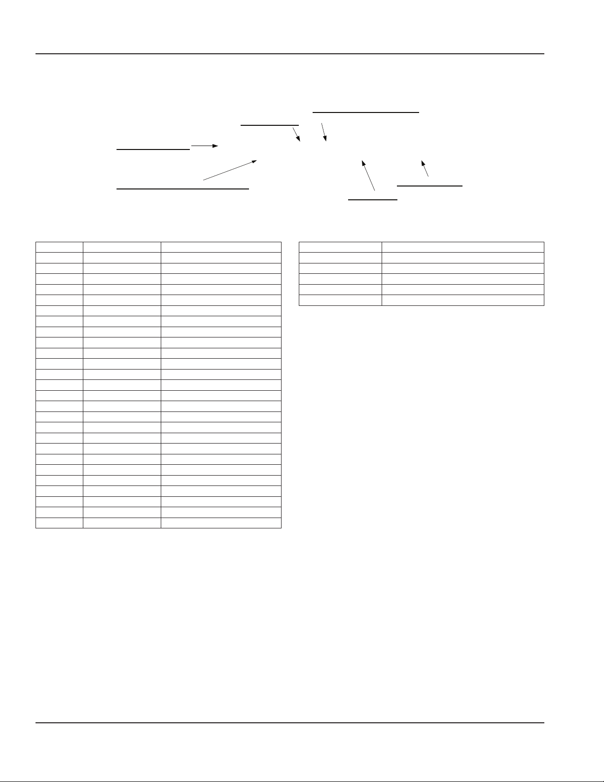
OVEN PLATFORM SIZE
(i.e. Impinger II)
INDICATES CHANGE TO BASE ASSEMBLY
(i.e. Natural Gas, 230V, 1 phase, 50 Hz)
CUSTOM CONFIGURATION CODE
PANEL SETUP CODE
Model Number Key
Example: 1130-000-U-K1801
11 33 B0–––0EK1801
Language Code
Code Language Country
0 English Dom. & Int. Default
B French CE – France/Luxembourg
C German CE – Germany
D Italian CE – Italy
E Spanish CE – Spain
F English CE – UK/India/Africa/Hungary
G Spanish Mexico/Latin America
H Portuguese CE – Portugal
I Not Used ---
J Danish CE – Denmark
K Dutch & French CE – Belgium
L Dutch CE – Netherlands
M Greek CE – Greece
N Finnish CE – Finland
O Restricted --P Norwegian CE – Norway
Q English Japan
R Swedish CE – Sweden
S English Australia
T Mandarin China
U Restricted --V English Pacific Rim/Korea
W English Middle East/Africa
X Not Used --Y Not Used --Z Not Used ---
LANGUAGE CODE
(i.e. General Market)
AGENCY CODE
Agency Code
Code Agency
N No agency
E CE & RoHS compliance combined
U US & Canada compliance only
A Advantage style oven
B Australia AGA
6 Part Number 4607056 Rev 0 6/21
Page 7
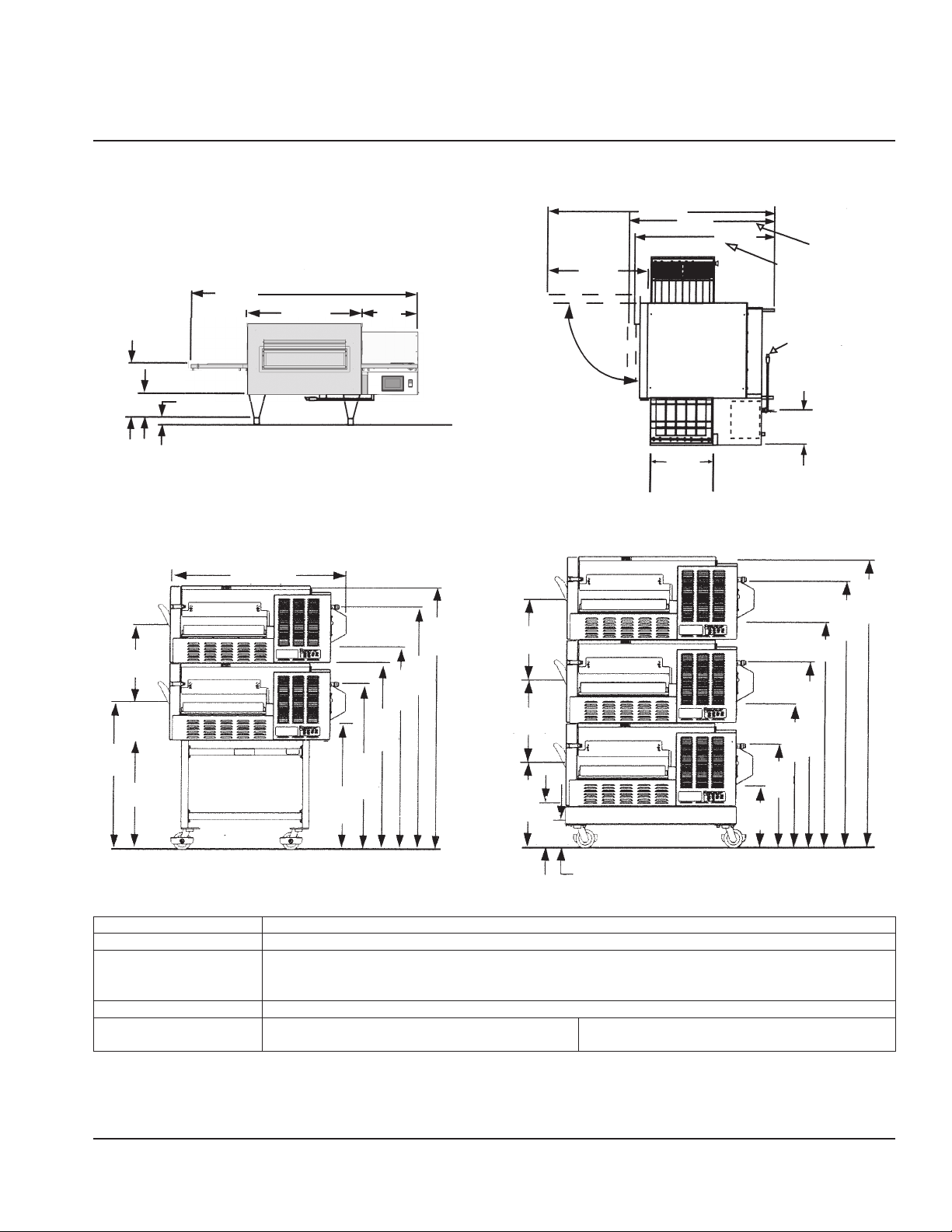
Exterior Dimensions
56"
(1422 mm)
13.5"
(343 mm)
1.5"
6"
(153 mm)
(38 mm)
28.25"
(718 mm)
13.63"
(346 mm)
Section 2
Installation
(Main Access
Door Open)
28"
90°
66.75"
(1695 mm)
(457 mm)
46.12"
(1171 mm) 43.62"
(1108 mm)
18"
Dimension with
Main Access Door
Closed; Optional
Glass Access Door
Open
Dimension with Main
Access Door Closed;
Optional Glass Access
Door Closed
NOTE:
Cord and Gas
Valve for Models
1115-000-A &
1117-000-A Only
10.5"
(267 mm)
39"
(914 mm)
(1575 mm)
57"
39.5"
(1003 mm)
30.5"
(1448 mm)
48"
(1219 mm)
32"
(813 mm)
17.5"
(444 mm)
7.5"
(191 mm)
24.5"
(622 mm)
(940 mm)
28"
(711 mm)
37"
45.5"
(1155 mm)
42"
(1067 mm)
59.5"
(1511 mm)
54.5"
(1384 mm)
17.5"
(444 mm)
17.5"
(444 mm)
17"
(432 mm)
(241 mm)
9.5"
5.75"
(146 mm)
(559 mm)
13"
(330 mm)
(775 mm)
22"
BODY: Stainless steel. Easy open front for simple cleaning.
POWER: Electric, or Gas and Electric
CONVEYOR: Stainless steel construction with flexible stainless steel belt, travel distances of 52 inches (1320 mm) with
24inches (610 mm) in the baking area. Conveyor belt width is 18 inches (460 mm). Speed range 50seconds
– 30 minutes.
DB LEVEL: ≤ 70dba
OPERATING
Gas 300° - 550° F (149° - 288° C) Electric 200° - 550° F (93° - 288° C)
TEMPERATURE RANGE:
62"
NOTE: Specifications are subject to change. Above data should be used for estimating purposes only.
U.S. Patent Nos.: 3,844,213 and 4,154,862; Other Patents Pending.
Part Number 4607056 Rev 0 6/21 7
Page 8
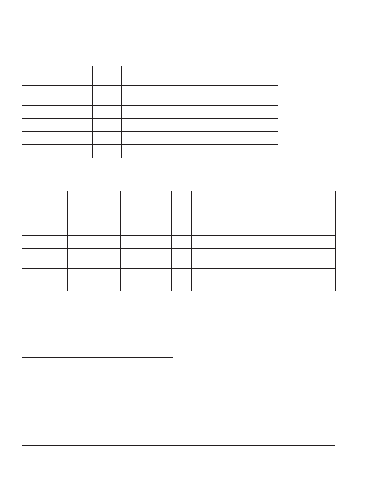
Installation Section 2
Utility Specifications
Electric Ovens
*Model Energy Power Voltage Current Phase Hz
1130-xxx-U-Kxxx Electric 10 kW 120/208V 48 Amps 1 60 Hz 4 Wires, 2 Pole + N + G
1131-xxx-U-Kxxx Electric 10 kW 120/240V 42 Amps 1 60 Hz 4 Wires, 2 Pole + N + G
1132-xxx-U-Kxxx Electric 10 kW 208V 28 Amps 3 60 Hz 4 Wires, 3 Pole + G
1133-xxx-U-Kxxx Electric 10 kW 240V 25 Amps 3 60 Hz 4 Wires, 3 Pole + G
1134-xxx-N-Kxxx Electric 10 kW 380/220V 15 Amps 3 50 Hz 5 Wires, 3 Pole + N + G
1134-xxx-N-Kxxx Electric 10 kW 380/220V 15 Amps 3 60 Hz 5 Wires, 3 Pole + N + G
1135-xxx-U-Kxxx Electric 10 kW 480V 25 Amps 3 60 Hz 4 Wires, 3 Pole + G
1151-xxx-U-Kxxx Electric 10 kW 200V 29 Amps 3 50/60 Hz 4 Wires, 3 Pole + G
1161-xxx-U-Kxxx Electric 10 kW 240V 42 Amps 1 60 Hz 3 Wires, 2 Pole + G
1162-xxx-U-Kxxx Electric 10 kW 208V 28 Amps 3 60 Hz 4 Wires, 3 Pole + G
1164-xxx-E-Kxxx Electric 10 kW 400V/230V 42 Amps 3 50 Hz 5 Wires, 3 Pole + N + G
1165-xxx-E-Kxxx Electric 10 kW 230V 25 Amps 3 50 Hz 4 Wires, 3 Pole + G
* Reference Model Number Key, Section 1.
** Ventless models are shown as 1164-xxx-V-Kxxx.
Recommended
Electrical Specification
Gas Ovens
Model Energy Power Voltage Current Phase Hz
1116-xxx-U-Kxxx Nat. Gas 40,000 BTU 120 VAC 7 Amps 1 60 Hz 3 Wires, 1 Pole + N + G
1117-xxx-U-Kxxx L.P. Gas 40,000 BTU 120 VAC 7 Amps 1 60 Hz 3 Wires, 1 Pole + N + G
1154-xxx-E-Kxxx Nat. Gas HS 13 kW 230 VAC 2 Amps 1 50 Hz 3 Wires, 1 Pole + N + G
1155-xxx-E-Kxxx L.P. Gas HS 13 kW 230 VAC 2 Amps 1 50 Hz 3 Wires, 1 Pole + N + G
1157-xxx-N-Kxxx Nat. Gas 40,000 BTU 230 VAC 2 Amps 1 50 Hz 3 Wires, 1 Pole + N + G 40,000 BTU @ 1.7 kPa
1158-xxx-N-Kxxx L.P. Gas 40,000 BTU 230 VAC 2 Amps 1 50 Hz 3 Wires, 1 Pole + N + G 40,000 BTU @ 2.3 kPa
1178-xxx-U-Kxxx Nat. Gas 40,000 BTU 120 VAC 7 Amps 1 60 Hz 3 Wires, 1 Pole + N + G
Recommended
Electrical Specification
Gas
40,000 BTU at 7 inches
H2O column**
40,000 BTU at 11 inches
H2O column**
HS 13 kW/HR at 1.7 kPa,
1.25 m3/hr
HS 13 kW/HR at 2.73 kPa,
.39 m3/hr
40,000 BTU at 7 inches
H2O column**
** NOTE: For proper operation, the gas valve requires a nominal inlet pressure of 7 inches of H2O for natural gas and 11 inches of H2O column for L.P. gas. A
minimum inlet pressure of 1.0 inch of H2O column above the manifold setting (NAT. manifold 3.5" H2O, L.P. manifold 10" H2O) must be maintained with no
pressure drop from the no load to full load condition. The maximum inlet pressure must be maintained at or below 1/2 PSIG (14.5 inches H2O column). Refer
to the chart in Section 1 for pressure conversions.
Electrical Supply for Australia:
Single Phase: 240 VAC, 50 Hz / 20 Amp; one neutral & one earth/ground.
Three Phase: 240/415 VAC / 20 Amp; three active, one neutral & one earth/ground.
All ovens require separate service and dedicated neutral.
Notice
Do not install the (these) oven(s) in any area with an
ambient temperature in excess of 95°F / 35° C. Doing so
will cause damage to the unit.
8 Part Number 4607056 Rev 0 6/21
Page 9
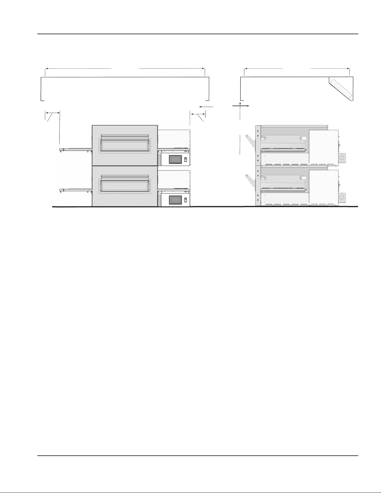
Section 2 Installation
Canopy Ventilation Recommendations
72"
(1829 mm)
Capture Area
6"
(153 mm)
AFF = Above Finished Floor
NOTE: The drawing shown is a typical installation and is
intended to be a guideline. It is not a rigid specification.
Hood dimensions and the positioning of the hood over the
oven will vary with hood manufacturers.
50"
(1270 mm)
Capture Area
Capture
Velocity
50-75 FPM
(914-1372
m/hour)
6"
(153 mm)
Height of Stand
78"
(1981 mm)
AFF TYP
NOTE: Lincoln can provide oven spec sheets that show
the dimensions of the oven, kW or BTU ratings and other
information that will be useful to both the ventilation hood
supplier and the HVAC contractor.
Part Number 4607056 Rev 0 6/21 9
Page 10
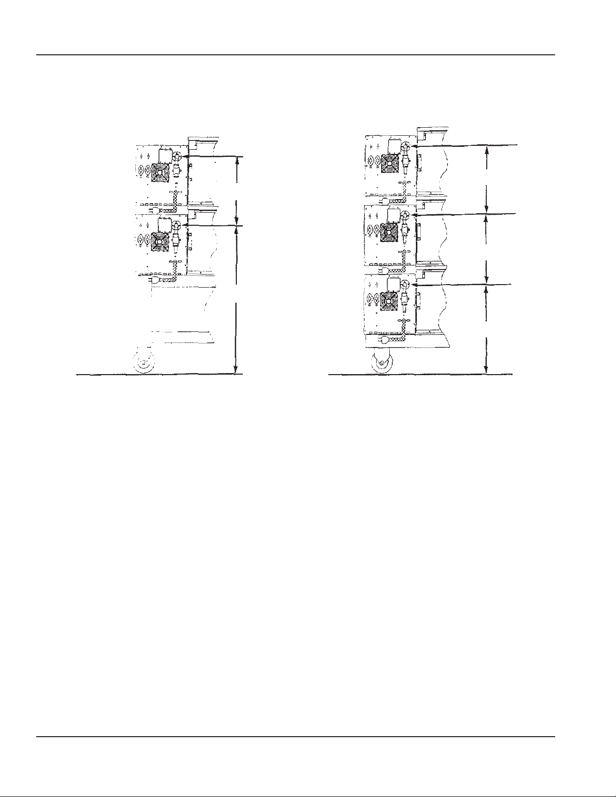
Installation Section 2
Utility Service Layout – Models 1116 & 1117
Gas and electrical services for the Models 1116 and 1117 should be located as shown below. If flexible services are provided,
they must meet code requirements for such installation.
17.5"
17.5"
(444 mm)
37"
(940 mm)
(444 mm)
17.5"
(444 mm)
22"
(559 mm)
Back view of two Impinger® II Gas Ovens showing
GasValve Installation and piping spacing.
Back view of three Impinger® II Gas Ovens showing
GasValve Installation and piping spacing.
10 Part Number 4607056 Rev 0 6/21
Page 11

Section 2 Installation
Installation Requirements
DANGER
All utility connections and fixtures must be maintained
in accordance with local and national codes.
GAS CODE REQUIREMENTS
Warning
n
A manual shut-off valve must be installed in the gas
supply (service) line upstream of this appliance so that
the test plug is on the oven side of the valve.
Safe and satisfactory operation of this oven depends to a
great extent upon its proper installation, and it should be
installed, as applicable in accordance with the National
Fuel Gas Codes, ANSI Z223.1/NFPA 54, latest version,
manufacturers’ installation instructions, local municipal
building codes, and ISO 203-1.
1. The oven and its individual shut off valve must be
disconnected from the gas supply piping system
during any pressure testing of that system at test
pressures in excess of 1/2 psig (3.45 kPa).
2. The oven must be isolated from the gas supply piping
system by closing its individual manual shutoff valve
during any pressure testing of the gas supply system at
test pressures equal to or less than 1/2 psig (3.45 kPa).
IN MASSACHUSETTS: The minimum length of a flexible gas
supply hose is thirty-six (36") inches.
IN CANADA: The installation of these appliances is to be in
accordance with CSA B.149.1 latest version – Natural Gas
and Propane Installation Code – and/or local codes.
IN AUSTRALIA: To be installed in accordance with AS 56012004 and 4563-2004 Gas Installation Code.
ELECTRICAL CODE REQUIREMENTS
Warning
n
This appliance must be properly grounded at time
of installation. Failure to ensure that this equipment
is properly grounded can result in electrocution,
dismemberment or fatal injury.
When installed, this appliance must be electrically
grounded and its installation must comply with the
National Electric Code, ANSI-NFPA 70, latest edition, the
manufacturers’ installation instructions, and applicable local
municipal building codes.
IN CANADA: All electrical connections are to be made
in accordance with CSA C22.2 latest version – Canadian
Electrical Code and/or local codes.
ALL OTHER COUNTRIES: Local gas and/or electrical codes
will prevail.
1. Strain Relief is provided with each oven. International
Dealer/Distributors provide applicable power cord/
plug for each customer.
2. All pole disconnection switch must have 3 mm open
contact distance.
3. To prevent electrical shock, an equal potential bonding
ground lug is provided in the back. This allows the oven
to be connected to an external bonding system.
4. If used as double or triple stack and each oven has its
own disconnection switch, all switches should be close
together.
Part Number 4607056 Rev 0 6/21 11
Page 12

Installation Section 2
SPACING REQUIREMENTS
Caution
,
Oven must be operated on an approved base only.
The oven must have 6 inches (152 mm) of clearance from
combustible surfaces. In case other equipment is located
on the right side of oven, a minimum clearance of 24 inches
(609 mm) is required from that equipment.
FOR ALL OVENS: A 24-inch (609 mm) clearance at the rear of
the oven must be obtainable for service access.
FOR PERMANENTLY INSTALLED OVENS: A permanently
installed (unmovable) oven requires a minimum of 4'
(1219mm) clearance on the right hand side to allow for
conveyor removal, cleaning, and servicing.
NOTE: Do not install this (these) oven(s) in any area with an
ambient temperature in excess of 95°F/35°C. Doing so will
cause damage to the unit.
VENTILATION REQUIREMENTS
A VENT IS REQUIRED: Local codes prevail. These are the
“authority having jurisdiction” as stated by the NATIONAL
FIRE PROTECTION ASSOCIATION, INC. in NFPA 96 latest
edition. In addition, to be in compliance with the NFPA 54
Section 10.3.5.2, this unit must be installed with a
ventilation hood interlock that prevents the unit from
operating when the ventilation hood is off. For further
ventilation information, see below.
Ventilation Guidelines
For standard ovens, a ventilation hood is required to
remove heat and cooking odors. Alternatively, optional
electric “ventless” models are available which incorporate
a catalyst to limit the emission of grease laden air to below
5mg/m3. Ventless ovens have been tested in accordance
with UL710B & EPA-202 and are listed by UL to the KNLZ
category. Ventless ovens should only be used for reheating
purposes and should not be used to cook raw animal
proteins, doing so may cause the appliance to exceed
allowable grease laden air limits and/or cause damage to
the catalyst. Ventless oven models can be identified by the
“-V-” suffix as part of their model number, refer to the spec
sheet for more details. When permitted by local code(s) and
used with appropriate food products, Lincoln “ventless”
ovens are not required to be installed under a ventilation
hood. For gas ovens, a ventilation hood is also required to
remove the products of combustion. The hood and HVAC
installation must meet local codes to gain approval by
the authority having jurisdiction. Requirements may vary
throughout the country depending on the location by city,
county, and state. Obtain information from the authority
having jurisdiction to determine the requirements for your
installation. Obtain information and review copies of codes
or documents that will be used to inspect and approve
your installation. Your ventilation hood supplier and HVAC
contractor should be contacted to provide guidance. A
properly engineered and installed ventilation hood and
HVAC system will expedite approval and reduce oven
maintenance costs. Proper ventilation is the oven owner’s
responsibility.
Lincoln 1100 ventless ovens equipped with a catalyst(s) are
approved for ventless operation while single or doublestacked only.
The ventilation hood must operate in harmony with the
building HVAC system. It typically requires between 750
and 2500 CFM (1274 and 4248 m3/hour) exhaust. (The
“Efficiency” of various hood designs makes it necessary
to specify such a wide range of ventilator flow.) Make
up air must be supplied by either a hood design or the
HVAC system. This will vary with hoods from various
manufacturers.
Notice
Prevent airflow through the cooking tunnel. Air must
NOT be directed onto the oven front or at side of cooking
area or rear of oven.
12 Part Number 4607056 Rev 0 6/21
Page 13
Section 2 Installation
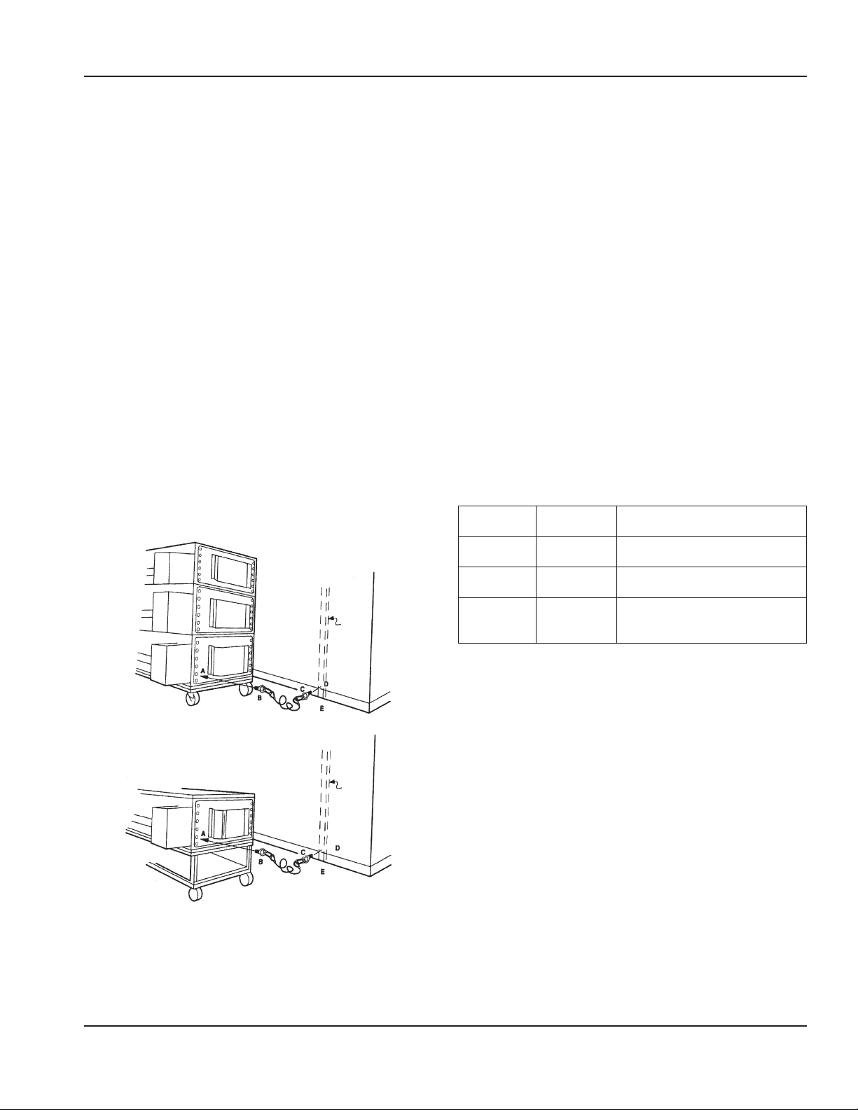
RESTRAINT REQUIREMENT GAS OVENS ON
CASTERS
• The installation shall be made with a gas connector
that complies with the local codes for Connectors for
Movable Gas Appliances, ANSI Z21.69 • CSA 6.16 latest
version, and a quick disconnect device that complies
with the local codes for Quick Disconnect Devices for
Use with Gas Fuel, ANSI Z21.41 • CSA 6.9 latest version.
• The installation of the restraint must limit the
movement of the oven(s) without depending on the
connector, the quick disconnect device or its associated
piping to limit the oven movement.
• If the restraint must be disconnected during
maintenance or cleaning, it must be reconnected after
the oven has been returned to its originally installed
position.
Procedure
1. Screw lifting eye end “B” of cable assembly to hole “A”.
Use 1/4" eye.
2. Screw eye bolt end “C” of cable assembly to stud in wall
“D” or floor anchor “E”.
NOTE: Installation point is the same for single, double, or
triple-stacked ovens.
Stud
Wall
Installation
The instructions that follow are intended as a guide for
preparing for the installation of the Impinger® Conveyor
Ovens. First and foremost, each crate should be examined
before signing the Bill of Lading to report any visible
damage by the trucker in transit, and to account for the
proper number of crates.
IF THERE IS APPARENT DAMAGE:
UNITED STATES AND CANADA: Arrangements should
be made to file a claim against the carrier, as Interstate
Commerce Regulations require that the consignee initiate
a claim.
ALL SHIPMENTS TO OTHER COUNTRIES: Freight terms will
be developed and extended on an individual basis.
Proper and secure storage facilities should be arranged for
the oven(s). If necessary, protect it from outdoor or damp
conditions at all times before installation.
PACKING AND WEIGHTS
All uncrated components of the Impinger® Conveyor Oven
will pass through a 30" (762 mm) wide door. The Impinger®
Conveyor Oven consists of:
Cartons or
Crates
1 – oven
(export)
1 – oven
(domestic)
1 – stand
(export &
domestic)
Weight of
Each
486 lbs.
(220.5 Kilo)
396 lbs.
(180.0 Kilo)
45 lbs.
(20.4 Kilo)
Dimensions of Each
43-1/2" x 63" x 24"
(1104.9 x 1600.2 x 609.6 mm)
42" x 59" x 23"
(1066.8 x 1498.6 x 584.2 mm)
42" x 26" x 5"
(1066.8 x 660.4 x 127 mm)
UNCRATING
When you have all the crates unloaded, open the crates and
Floor
remove the plastic covers. Inspect at once for concealed
damage. If anything appears to be damaged, contact the
appropriate persons immediately to file a damage claim.
Back of Single Oven
Stud
After completing this inspection, finish unpacking the oven
and all other components. Be sure to remove the packing
cardboard from the plenum shroud. Move all components
Wall
inside near the area where they will be assembled in the
order in which they will be assembled.
Floor
Part Number 4607056 Rev 0 6/21 13
Page 14
Installation Section 2
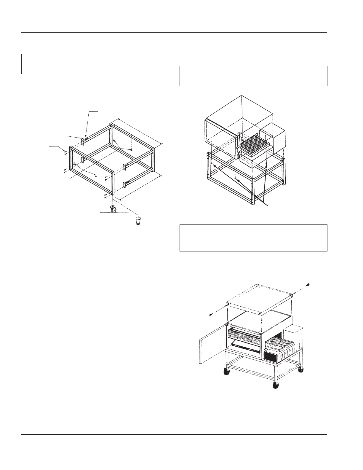
Assembly Instruction
Notice
DO NOT OVERTIGHTEN NUTS AND CRUSH TUBING!
Position the two side pieces so that the holes for the oven
mounting are as shown.
ACORN NUT
1/4" - 20
41.5"
LOCKWASHER
1/4"
BOLT STEP
1/4" - 20 x 1-7/8
SCREW
1/4" - 20 x 2
CASTER
(1054 mm)
28.5"
(726 mm)
Stacking Instructions
FOR SINGLE OVEN
Caution
,
Do not use standoffs as a lifting means.
Screw 1/4 - 20 x 2
Use 4 each
LEG
Caution
,
Use extreme care so oven does not slip off stand before
screws have secured oven.
FOR DOUBLE OVEN
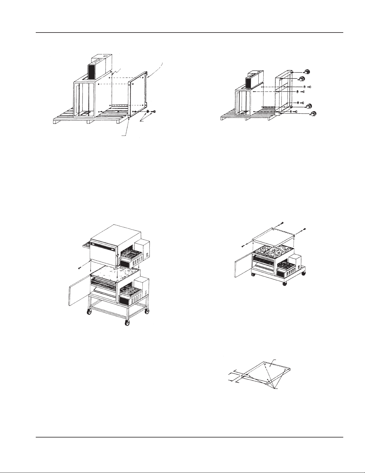
Step 1
Bottom Unit
1. Remove 4 screws holding top in place and save (2 in
front, 2 in rear).
14 Part Number 4607056 Rev 0 6/21
Page 15
Section 2 Installation
Step 2
NOTE: Notch (In Top)
to Rear of Unit.
1/4-20
Lockwasher
and 1/4-20
TOP
x 1/2 Hex
Head Bolt
Top Unit
1. Remove door, conveyor and finger assemblies.
2. Turn unit on left side, as shown.
3. Drill holes in cover, as shown. Refer to Step 3 in “For
Triple Oven”.
4. Assemble top of bottom unit to bottom of top unit with
4 bolts, as shown.
Step 3
FOR TRIPLE OVEN
Step 1
1. Remove door, conveyor and finger assemblies.
2. Turn unit on side, as shown.
3. Remove three screws from Front Cover.
4. Fasten base to oven with four 1/2 - 13 x 1/2" long Hex
Head Bolts. Be sure to align the holes at the front of the
oven and stand first.
NOTE: The front edge of the stand should line up with the
front edge of the oven.
5. Screw casters into base.
Step 2
1. Set oven upright.
2. Remove oven top by removing 2 screws in front and 2
screws in back.
(Save the screws.)
Stacking Units
1. Position top unit over top of bottom unit and align top
flanges with bottom unit.
2. Replace 4 screws, as shown (2 in front, 2 in rear).
3. Replace door, conveyor and fingers.
Step 3
TOP
From Bottom Unit
7/8
3. Replace door, conveyor and finger assemblies.
4. Stacking is complete.
3-1/4
DRILL 5/16 Dia.
(4) Holes
1. Prepare top for mounting as shown above.
Part Number 4607056 Rev 0 6/21 15
Page 16
Installation Section 2
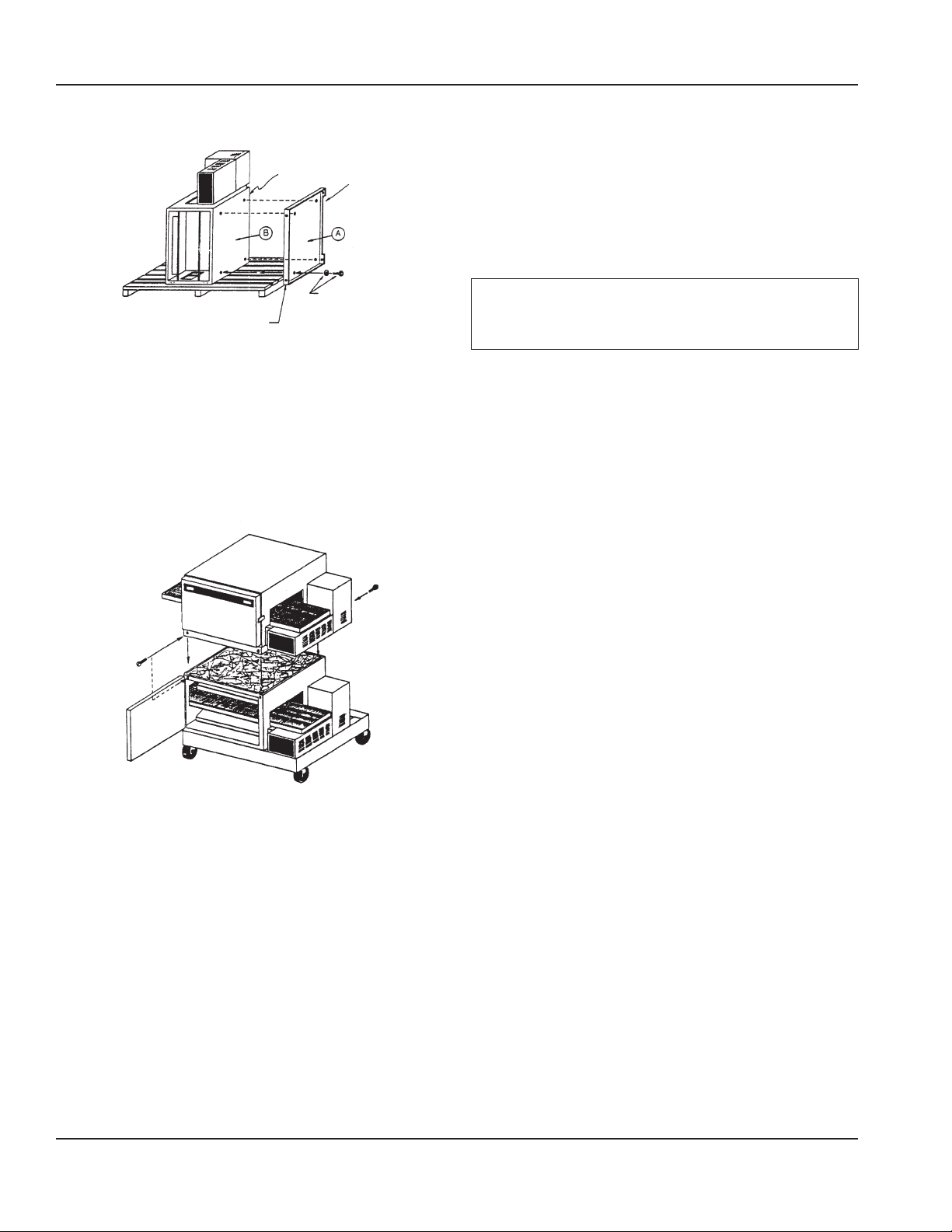
Step 4
NOTE: Notch (In Top)
to Rear of Unit.
1/4-20
Lockwasher
TOP
and 1/4-20
x 1/2 Hex
Head Bolt
Oven to be Stacked
1. Remove door, conveyor and finger assemblies.
2. Turn unit on left side, as shown.
3. Assemble top of bottom unit to bottom of top unit with
4 bolts, as shown.
Step 5
Start-Up Checkout
You are now ready for the services to be connected.
This should be done by a qualified plumber, electrician,
or installer of your choice. For installation in the state of
Massachusetts: installation of this oven must be performed
by a licensed plumber or gas fitter. Refer to Utility
Specifications and Installation Requirements sections for
additional information.
Important
The manual shut-off valve must be installed so that the
test plug is on the oven side of the valve.
1. Position top oven over bottom and align the top oven
flanges over the outside of the bottom oven, as shown.
2. Lower oven in place.
3. Fasten ovens together using the four screws from
Step2 (2-front, 2-back).
4. Replace door, conveyor and fingers.
5. Repeat Steps 2 – 5 to stack third oven.
16 Part Number 4607056 Rev 0 6/21
Page 17

Section 2 Installation
Start-Up Procedures
SMOKE CANDLE TEST VENTILATION SYSTEM
VERIFICATION
Performance will be evaluated during Start-up Checkout
by conducting a smoke candle test. The hood must capture
all smoke from the oven. This is required to assure proper
performance of the oven and to eliminate additional service
calls that occur when ambient temperatures are too high.
In all cases, the ambient temperature around the oven
must be less than 95°F/35°C when the oven is operating.
In certain localities, other chemical or gaseous methods
of detecting adequate capture will be the requirement to
meet the local code authority.
Oven Setup for this Test:
• This test is to be done on the bottom oven of a multiple
oven system, or a single oven.
• The conveyor must be off.
• The oven temperature must be set and operating at
550°F/288°C.
Test Procedure:
NOTE: Use Lincoln Smoke Candle #369361 (in Australia, an
alternate method of coloring the air may be used).
1. Wear heat resistant gloves to prevent burns to your
hands.
2. Put the smoke candle in a cake pan approximately
8 inches (200 mm) x 8 inches (200 mm) x 2 inches
(50 mm) deep or equivalent.
3. Open the optional access window in the oven door, or
insert candle through conveyor opening.
4. Light the fuse of the smoke candle and immediately
put the pan and candle into the center of the oven
cavity, on the conveyor belt. (Close the access window
or door.)
5. Observe the smoke pattern coming out of the oven
openings and the collection of this smoke by the
ventilation system.
6. The ventilation system must capture all the smoke from
the oven.
Installation Checklist
DANGER
Check all wiring connections, including factory
terminals, before operation. Connections can become
loose during shipment and installation.
Warning
n
On completion of any installation or service work, test for
gas leaks before returning the equipment into service.
Never use matches, candles, or any other ignition source
to check for leaks. If gas odors are detected, shut off the
gas supply to the appliance at the main shut-off valve
and immediately contact the local gas company or an
authorized service agency for service.
DO NOT ATTEMPT TO OPERATE THE OVEN until connection
of utility service and installation has been fully inspected
(START-UP CHECKOUT) by a Factory Authorized Servicer or
a Lincoln Foodservice Products, LLC Service Representative.
This service is required by Lincoln Foodservice Products,
LLC in order to insure the oven(s) is properly installed and
in working order. The warranty becomes effective upon
verification of proper installation.
The warranty shall not apply if the oven is started up
and operated prior to the “START-UP CHECKOUT” being
performed by a Factory Authorized Servicer or a Lincoln
Foodservice Products, LLC Service Representative.
Part Number 4607056 Rev 0 6/21 17
Page 18

Installation Section 2
CHECKLIST
Are the correct clearances maintained?
Does the ventilation system meet the requirements?
Are the legs and caster securely fastened?
Is the unit level?
Has the restraint been installed to prevent uncontrolled
movement?
Have all electrical connections been made and the unit
is grounded?
Does each oven have a separate disconnect switch?
Have all wiring connections including the factory
connections been checked?
Has the supply voltage been tested and verified it
matches the name plate voltage?
Has a shutoff valve been installed in the gas line ahead
of the unit?
Has the manifold gas pressure been set to match the
rating on the nameplate?
Have all gas connections been tested for leaks?
Are the retaining brackets and finger assemblies
correctly installed and positioned?
Is the belt tension correct?
Have access panels been installed and secured?
Has a smoke candle test been performed?
Has the unit been tested for correct operation?
Has the owner been instructed in the correct operation
of the unit?
Has this manual been given to the store owner?
18 Part Number 4607056 Rev 0 6/21
Page 19
Section 3
Operation and Programming
Introduction
This section will help guide you on the operation of the new
easyTouch controls.
Startup
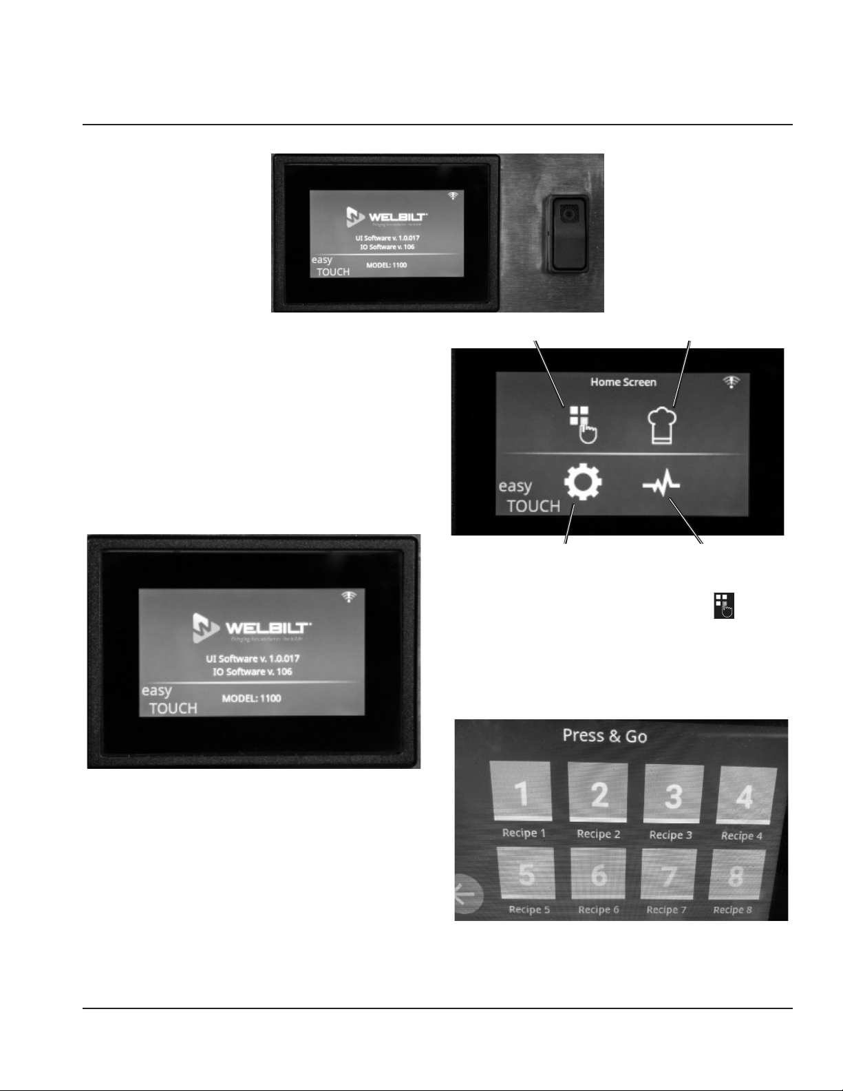
1. Ensure that your oven is connected to an electrical
supply. Move the On/Off switch to the ON position
• The display screen will energize and show the
Lincoln oven model number and current software
version. This screen will transition after a few
seconds to the Home Screen. (Figure 1)
Press & Go
Settings
Figure 2
RECIPE SELECTION [PRESS & GO BUTTON]
1. Touch the Press & Go button to display the 8 pre-set
recipes. Press any of the 8 color recipe buttons to select
the recipe. (Figure 3)
A. The display screen will change to show the settings
for the recipe selected.
Manual Mode
Diagnostics
Figure 1
NOTE: The oven will not start pre-heating until you
have selected a recipe.
2. The Home screen displays 4 buttons: Press & Go,
which takes you to the Recipes screen; Manual mode;
the Settings screen; and the Diagnostics button,
which provides basic information about your oven.
(Figure 2)
Figure 3
Part Number 4607056 Rev 0 6/21 19
Page 20
Operation and Programming Section 3
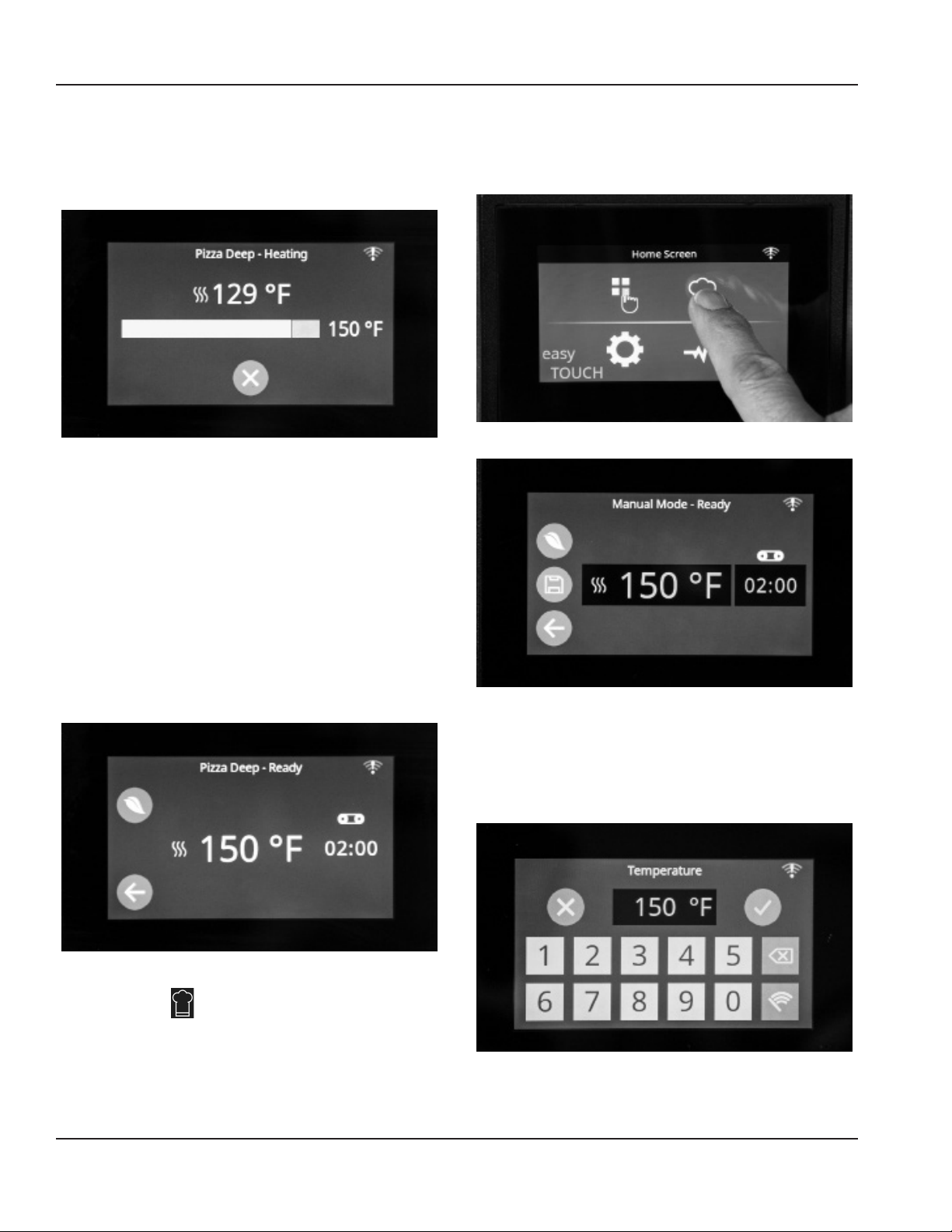
2. The oven is now in pre-heat mode and the oven
heaters will start-up. The temperature settings appear
on the screen. You will see the temperature of the oven
and the temperature increasing up to the set-point.
The conveyor does not move in pre-heat mode.
Figure 4
A. When the oven reaches the set-point
temperature, the conveyor belt will start to
move. The display will show the selected set-point
temperature and belt speed [cook time].
3. Oven Soak – allow the oven cavity to soak for an
additional 5-10 minutes before loading food
4. Load Food – The oven is now ready for cooking. Please
use the proper equipment to load and unload food
from the conveyor. The conveyor will be hot to the
touch. Pans or trays exiting the oven will be VERY HOT
and are a burn hazard. Please use an oven mitt, pan
gripper or other utensil to remove.
CHANGING TEMPERATURE AND COOK TIME [BELT
SPEED]
1. Press the Chef’s Hat or Manual mode button on the
Home screen. (Figure 6 and Figure 7)
Figure 6
Figure 7
2. Press the temperature button to change temperature.
Touch the numbers to correspond to the temperature
required. Press 4-5-0 for 450 degrees and then touch
the check mark to save the new temperature or X to
return to the original setting. (Figure 8 and Figure 9)
Figure 5
MANUAL MODE
Manual mode allows the operator to change the
temperature and cook time to revise or create a new recipe.
Figure 8
20 Part Number 4607056 Rev 0 6/21
Page 21
Section 3 Operation and Programming
SETTINGS MODE
Settings mode allows the operator to change the oven
settings such as Temperature unit of measure or Belt
direction. The factory temperature unit of measure is
Fahrenheit.
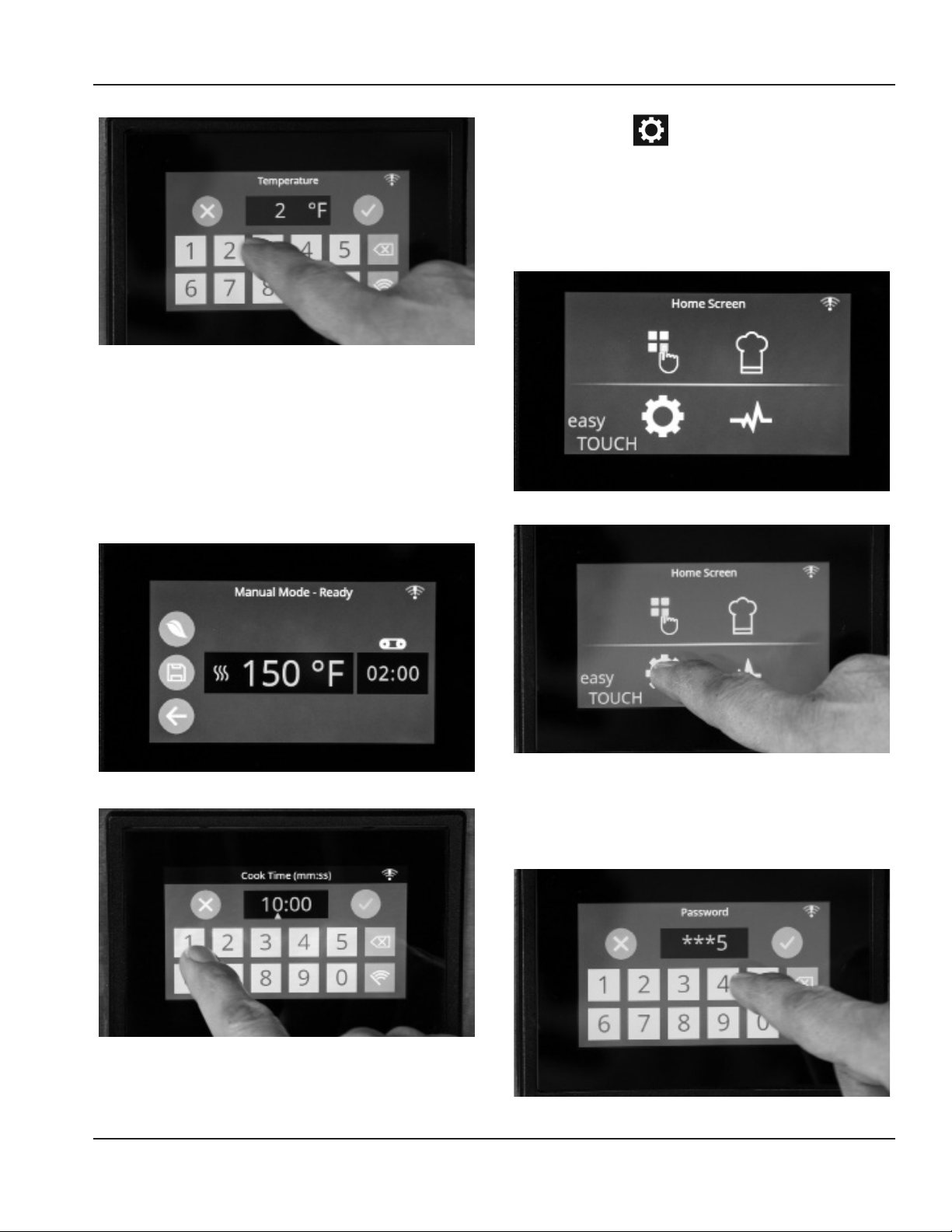
1. Press the Cog or Settings mode button on the Home
screen. (Figure 13 and Figure 12)
Figure 9
3. Press the belt speed button to change cook time. Touch
the numbers to correspond to the cook time required.
Press 0-4-0-0 for 4 minutes and then touch the check
mark to save the new cook time or X to return to the
original setting.
4. You can return to the Home screen at any time by
pressing the Back button or arrow on the lower left of
the screen.
Figure 12
Figure 13
Figure 10
Figure 11
Part Number 4607056 Rev 0 6/21 21
2. Enter the password by touching the numbers on
the password screen. The password is: 6-7-8-5-3-5.
This password is pre-set at the factory and is not
changeable. (Figure 14)
Figure 14
Page 22
Operation and Programming Section 3
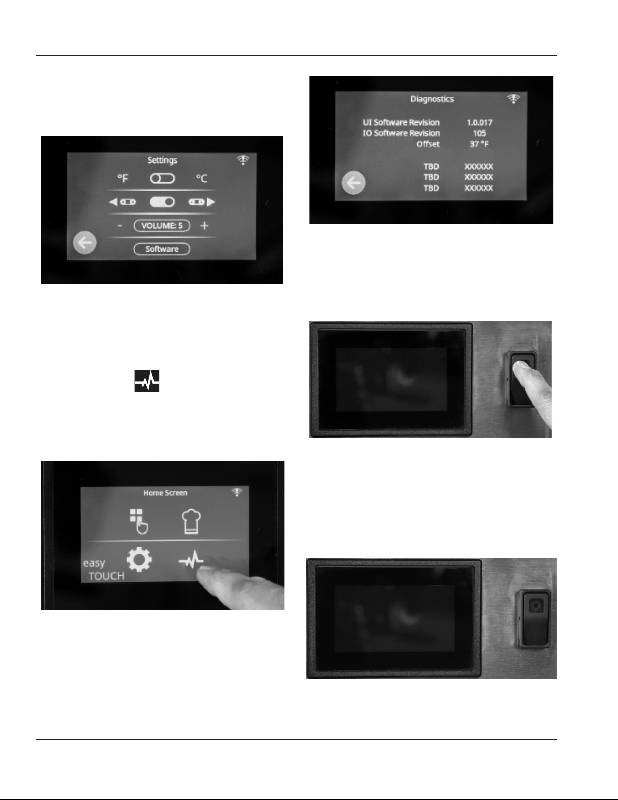
3. Temperature Measure - Touch the white circle in the
oval button on the Settings display that shows the
temperature measure. The Fahrenheit or Celsius symbol
will change to correspond to the desired temperature
unit of measure. (Figure 15)
Figure 17
OVEN SHUT DOWN
1. To shut down your oven, press the Back Button to
Figure 15
4. Belt Direction - Touch the white circle in the oval button
on the Settings display that looks like a mini conveyor.
The mini conveyor will change to correspond to the
desired belt direction. The new belt direction is now
set.
return to the Home screen. The conveyor should stop
moving; however, the cooling fan will continue to run if
the oven is hot. (Figure 18)
DIAGNOSTICS MODE
Diagnostics mode allows the operator to view basic
information about your oven including software revisions
and temperature offsets.
1. Press the Diagnostics button on the Home screen to
access this mode. (Figure 16)
Figure 16
2. Press the Back button or arrow to return to the Home
screen. (Figure 17)
Figure 18
2. Turn OFF the On/Off switch. (Figure 19)
A. Your oven is now turned off. Please continue to
keep the oven connected to an electrical source to
enable the cooling fan and cooking fan to continue
to operate to cool down the oven. The fans could
run for up to an hour after turning off the oven to
cool the oven and protect critical components.
Figure 19
22 Part Number 4607056 Rev 0 6/21
Page 23

Section 4
Maintenance
Operator Maintenance
DANGER
Disconnect power supply before servicing or cleaning
this oven. Safeguard power so it cannot be accidentally
restored. Failure to do so could result in dismemberment,
electrocution, or fatal injury.
Extensive engineering went into this oven to make it
as maintenance free as possible. There is no lubrication
required.
However, to achieve the maximum efficiency of the oven,
it is necessary to keep it clean. For cleaning instructions,
see below. The frequency listed is only the factory’s
recommendations. Your use and type of products will
actually determine the frequency of cleaning.
If the oven fails to operate, check the circuit breaker and gas
valve to be sure they are turned on. Also, check the fuses on
the control panel to be sure that they are good before you
call the Factory Authorized Servicer. The name and phone
number of the Factory Authorized Servicer should be
located on the oven or contact the factory at (844) 724-2273
for the name of the nearest Factory Authorized Servicer.
CLEANING INSTRUCTIONS
The Lincoln Impinger oven contains electrical components.
Before cleaning the oven, switch off and disconnect the
oven from the electrical supply.
No electrical components should be subjected to moisture.
It is, therefore, important that the oven is wiped down
carefully. NEVER throw buckets of water over the oven or
subject it to pressure washing from a hose or a pressure
spray. If water or other liquid is spilled on the oven, make
sure that none has entered the control box area before
switching on. If in doubt, call your service company.
Notice
Do not use caustic or alkaline cleaners on interior of the
unit or on catalyst(s) of ventless ovens. These cleaners
can damage the specially finished surfaces of the unit
interior.
Daily Cleaning
1. Clean exterior surfaces of the oven by wiping it down
with a mild detergent and clean water, or a commercial
stainless cleaner.
2. Clean crumb pans and guards by washing with a mild
detergent solution and rinsing with clean water.
3. Clean the interior by sweeping up all loose particles,
then wash with a mild detergent solution and rinse
with clean water.
4. Clean the conveyor belt by wiping with a clean
cloth or use a scrub brush (Lincoln Catalog Number
11000115638).
On exterior of oven, deposits of baked-on splatter, oil,
grease, or light discoloration may be removed with any
of several commercial cleaners. Consult with your local
supplier.
Caution
,
Do not spray chemicals or cleaning liquids directly on
catalyst [ventless ovens]. Clean catalyst with damp cloth
only. The catalyst must be kept clean and unobstructed
to be effective.
Warning
n
When using cleaning solutions, be sure they meet local
and national health standards.
Caution
,
Oven must be cool. Do not use power-cleaning
equipment, steel wool, or wire brushes on stainless steel
surfaces.
Part Number 4607056 Rev 0 6/21 23
Weekly Cleaning
1. Remove fingers, disassemble and clean. See “Finger
Removal” section for more information.
2. Remove conveyor, disassemble and clean. See
“Conveyor Removal” section for more information.
NOTE: Be sure to clean and inspect the ventilation hood,
in accordance with the ventilation hood manufacturer’s
specifications.
Page 24
Maintenance Section 4
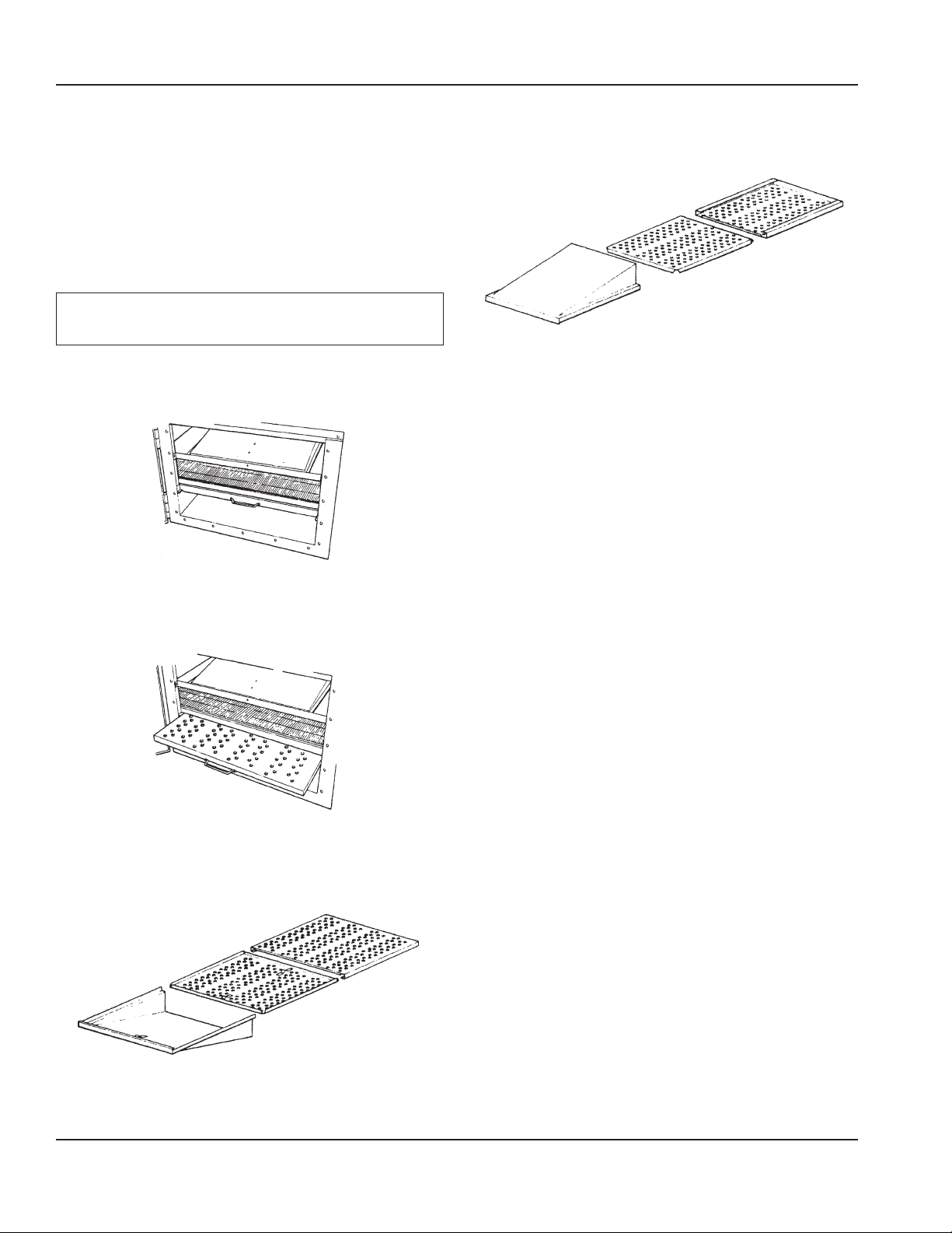
Conveyor Removal
1. Remove door from front of oven by unfastening the
latching mechanisms on the left side of the door
(facing oven).
2. Pull conveyor out from oven baking chamber.
3. Re-install in reverse order.
Finger Removal
Caution
,
Oven must be cool.
1. Open Door.
NOTE: Door may be removed by lifting from hinges.
2. Grasp top finger housing, lift up from bracket and pull
forward.
4. Slide finger cover from housing. Lift out inner
Columnating Plate.
Finger
Cover
Columnating
Plate
Finger
Housing
Top Finger Assembly
5. Reassemble in reverse order. Be sure finger assembly
seats securely over rear openings.
Preventive Maintenance
Although this oven has been designed to be as troublefree as possible, periodic preventive maintenance is
essential to maintain peak performance. It is necessary to
keep the motors, fans, and electronic controls free of dirt,
dust and debris to ensure proper cooling. Overheating
is detrimental to the life of all components mentioned.
The periodic intervals for preventive cleaning may
vary greatly depending on the environment in which
the oven is operating. You must discuss the need for
preventive maintenance with your Factory Authorized
Servicer to establish a proper program. If there are any
questions that the service agency cannot answer, please
contact the KitchenCare Technical Service Department at
(844) 724-2273.
3. Grasp bottom finger housing handle and pull forward,
sliding assembly out of oven.
Finger
Cover
Columnating
Plate
Finger
Housing
Bottom Finger Assembly
24 Part Number 4607056 Rev 0 6/21
Page 25

Section 5
Troubleshooting
Before Calling for Service Checklist
Problem Cause Correction
Doesn’t operate Breaker tripped Reset breaker
Manual gas valve off Put valve in ON position
Fuses not good Replace fuses on the back of oven
Safety thermal cut-out trips Reset power, call for service if it repeats
Uneven heating Fingers incorrectly assembled Reassemble correctly
Fingers in wrong location Place fingers in correct location
Over or under cooked Incorrect temperature setting Adjust temperature
Incorrect conveyor speed Adjust conveyor speed
Defective thermostat Call for service
Heat and cooking odors spill into room Ventilation/exhaust hood is off Energize the ventilation system
Ventilation/exhaust filters require cleaning Clean all filters
Defective ventilation/exhaust system Call for service
Conveyor does not operate Incorrectly installed Remove and reinstall
Drive sprocket is loose Tighten drive sprocket
Drive chain loose or disconnected Verify installation is correct - Call for service
Conveyor has stretched from use Call for service
Thermal Cut-Out Switch for Control Box
Components
The Impinger II unit includes a “safety thermal cut-out
switch” for your protection. This safety related device is
designed to ensure that the unit will not overheat and
damage the oven. In the unlikely event that the oven would
exceed the specified operating temperature range, the
“safety thermal cut-out switch” will activate, thus blocking
power to the unit and causing it to turn off.
Warning
n
In order to avoid a hazard due to inadvertent resetting of
the thermal cutout, this appliance must not be supplied
through an external switching device, such as a timer or
connected to a circuit that is regularly switched on and
off by the utility.
How to Obtain Service
The name and phone number of the Factory
Authorized Servicer should be located on the oven or
contact KitchenCare Technical Service Department at
(844)724-2273 for the name of the nearest agency.
Part Number 4607056 Rev 0 6/21 25
Page 26

Troubleshooting Section 5
THIS PAGE INTENTIONALLY LEFT BLANK
26 Part Number 4607056 Rev 0 6/21
Page 27

LIMITED WARRANTY, TERMS AND CONDITIONS
LINCOLN EQUIPMENT LIMITED WARRANTY
Lincoln Foodservice (“Lincoln”) warrants this product to be free from defects in material
and workmanship as follows:
• 2424 Electric, Electric Ventless and Gas ovens for a period of two (2) years from
date of purchase
• Equipment must be installed within 12 months from date of manufacture.
Note: Warranty terms may vary based on agreement at time of purchase.
During the warranty period, Lincoln shall repair or, at Lincoln’s option, replace parts
determined by Lincoln to be defective in material or workmanship, and with respect
to services, shall re-perform any defective portion of said services. The foregoing
shall be the sole obligation of Lincoln under this Limited Warranty with respect to the
equipment, products and services. With respect to equipment, materials, parts and
accessories manufactured by others, Lincoln’s sole obligation shall be to use reasonable
efforts to obtain the full benefit of the manufacturers’ warranties. Lincoln shall have no
liability, whether in contract, tort, negligence, or otherwise, with respect to non-Lincoln
manufactured products.
WHO IS COVERED
This Limited Warranty is available only to the original purchaser of the product and is not
transferable.
EXCLUSIONS FROM COVERAGE
• Repair or replacement of parts required because of misuse, improper care or
storage, negligence, alteration, accident, use of incompatible supplies or lack of
specified maintenance shall be excluded.
• Normal maintenance items, including but not limited to, fuses, conveyor belt,
conveyor bearings, interior and exterior finishes, lubrication, oven pass-through
glass door, door hinges, etc.
• Adjustments and calibration of temperatures, speed and air flows.
• Failures caused by erratic voltages or gas supplies.
• Any travel costs beyond 100 miles roundtrip or 2 hours travel other than overland,
overtime, holiday charge, and any special arrangement.
• Any travel costs above actual time (One-way travel ONLY paid).
• Any charges additional to the SRT (Standard Repair Times) will be authorized and
paid at the discretion of Lincoln.
• Improper or unauthorized repair.
• This Limited Warranty will not apply to any parts subject to damage beyond the
control of Lincoln, or to equipment which has been subject to alteration, misuse or
improper installation, accidents, damage in shipment, fire, floods, power changes,
other hazards or acts of God that are beyond the control of Lincoln.
• This Limited Warranty does not apply and shall not cover any products or
equipment manufactured or sold by Lincoln when such products or commercial
equipment is installed or used in a residential or non-commercial application.
Installations not within the applicable building or fire codes render this Limited
Warranty and any responsibility or obligations associated therein null and void.
This includes any damage, costs or legal actions resulting from the installation
of any Lincoln manufactured commercial cooking or warming equipment in a
non-commercial application or installation, where the equipment is being used for
applications other than those approved for by Lincoln.
• With respect to equipment, materials, parts and accessories manufactured by
others, Lincoln’s sole obligation shall be to use reasonable efforts to obtain the full
benefit of the manufacturers’ warranties. Lincoln shall have no liability, whether in
contract, tort, negligence, or otherwise, with respect to non-Lincoln manufactured
products.
LIMITATIONS OF LIABILITY
The preceding paragraphs set forth the exclusive remedy for all claims based on failure
of, or defect in, products or services sold hereunder, whether the failure or defect arises
before or during the warranty period, and whether a claim, however instituted, is based
on contract, indemnity, warranty, tort (including negligence), strict liability, implied
by statute, common-law or otherwise. Lincoln, its servants and agents shall not be
liable for any claims for personal injuries or consequential damages or loss, howsoever
caused. Upon the expiration of the warranty period, all such liability shall terminate. THE
FOREGOING WARRANTIES ARE EXCLUSIVE AND IN LIEU OF ALL OTHER WARRANTIES,
WHETHER WRITTEN, ORAL, IMPLIED OR STATUTORY. NO IMPLIED WARRANTY OF
MERCHANTABILITY OR FITNESS FOR PARTICULAR PURPOSE SHALL APPLY. LINCOLN DOES
NOT WARRANT ANY PRODUCTS OR SERVICES OF OTHERS.
REMEDIES
• The liability of Lincoln for breach of any warranty obligation hereunder is limited
to: (i) the repair or replacement of the equipment on which the liability is based, or
with respect to services, re-performance of the services; or (ii) at Lincoln’s option,
the refund of the amount paid for said equipment or services.
• Any breach by Lincoln with respect to any item or unit of equipment or services
shall be deemed a breach with respect to that item or unit or service only.
WARRANTY CLAIM PROCEDURE
• Immediately advise the Dealer or Lincoln’s Factory Authorized Servicer of the
equipment serial number and the nature of the problem.
• Verify the problem is a factory responsibility. Improper installation or misuse of
equipment are not covered under this Limited Warranty.
• Cooperate with the Service Agency so that warranty service may be completed
during normal working hours.
GOVERNING LAW
Limited Warranty shall be governed by the laws of the state of Delaware, USA, excluding
their conflicts of law principles. The United Nations Convention on Contracts for the
International Sale of Goods is hereby excluded in its entirety from application to this
Limited Warranty.
INTERNATIONAL SALES POLICY
International sales orders submitted by US dealers are subject to the following up
charge:
• 2424 Asperion Whisper Oven – 20%
• lmpinger II, lmpinger I, Low Profile, 3200 Series ovens - 20%.
• Countertop Oven (DCTI - 2500 series) - 15%.
All shipments FOB Covington, TN 38019
Page 28
LINCOLN
11200 AIRPORT NORTH OFFICE PARK STE. A&B, FORT WAYNE, IN 46825
844-724-2273
WWW.LINCOLNFP.COM
©2021 Welbilt, Inc. except where explicitly stated otherwise. All rights reserved.
Part Number 4607056 Rev 0 6/21
 Loading...