

Page 1
PARTS & SERVICE MANUAL
Impinger II Express Series
International Models
MODELS:
Please note that the model numberi ng system changed
March 2007. The chart below shows the old model
numbering system and its matching new model number
system. Please see Model Number Key section on next
page for additional information.
Old Model Number
1154-000-EA
1154-080-EA
1154-V80-EA
1155-000-EA
1155-080-EA
1155-V80-EA
1164-000-EA
1164-080-EA
New Model Number
→
1154-z00-U-Kxxxx
→
1154-z00-U-Kxxxx
→
1157-z00-U-Kxxxx
→
1155-z00-U-Kxxxx
→
1155-z00-U-Kxxxx
→
1158-z00-U-Kxxxx
→
1164-z00-U-Kxxxx
→
1164-z00-U-Kxxxx
→
P/N: L371086
REV: 10.21.09
Lincoln Foodservice Products, LLC
1111 North Hadley Road
Fort Wayne, Indiana 46804
Telephone: 260.459.8200
Fax: 260.436.0735
Technical Support: 260.459.8200
lincolnfp.com
Page 2
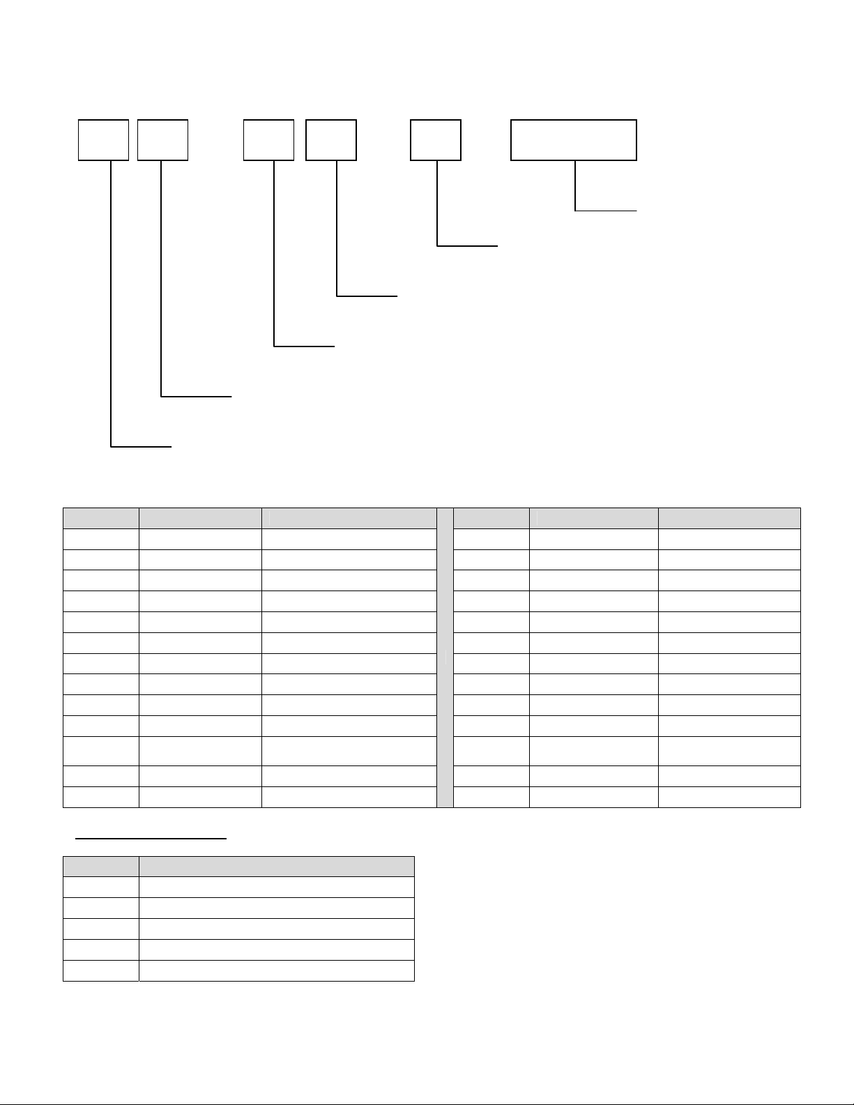
MODEL NUMBER KEY
EXAMPLE: 1154-B00-E-K1801
11 54 - B 00 - E - K1801
Agency Code (i.e. CE & RoHS combined)
Custom Configuration Code (i.e. General Market Version)
Language Code
Indicates change to base assembly (i.e. Natural Gas, 230V, 1 phase, 50 Hz)
Oven Platform Size (i.e. Impinger II)
CODE LANGUAGE COUNTRY CODE LANGUAGE COUNTRY
0 English Dom. & Int. Default N Finnish Finland
B French France/Luxembourg O Restricted --C German Germany P Norwegian Norway
D Italian Italy Q English Japan
E Spanish Spain R Swedish Sweden
F English UK/India/Africa/Hungary S English Australia
G Spanish Mexico/Latin America T Mandarin China
H Portuguese Portugal U Restricted ---
I Not Used --- V English Pacific Rim/Korea
J Danish Denmark W English Middle East
K
L Dutch Netherlands Y Not Used --M Greek Greece Z Not Used ---
Dutch &
French
Belgium X Not Used ---
AGENCY CODE TABLE
CODE AGENCY
N No Agency
E CE & RoHS compliance combined
U US & Canada compliance only
A Advantage style oven to be phase d-out
B Australia AGA
Panel Setup Code
2
Impinger II – Advantage Digital Express Service Manual - International
Page 3

SEQUENCE OF OPERATIONS
IMPINGER II ADVANTAGE DIGITAL EXPRESS
SERIES 1154 EXPORT NAT. GAS 230VAC 50 HZ. 1 PHASE
SERIES 1155 EXPORT LP GAS 230VAC 50 HZ. 1 PHASE
SERIES 1157 EXPORT NAT. GAS 230VAC 50/60HZ 1 PHASE
SERIES 1158 EXPORT LP GAS 230VAC 50/60HZ 1 PHASE
POWER SUPPLY Electrical power to be supplied to the oven by a three conductor service.
CONTROL BOX AUTO
COOL DOWN
MAIN FAN CIRCUIT
Burner does not go through
filter.
BURNER CIRCUIT Closing the oven fan switch supplies line voltage through the normally open air
IGNITION CONTROL The ignition control switches line voltage to the combustion blower motor. The
TEMPERATURE CONTROL Closing the oven fan switch supplies line voltage to the primary of the control
CONVEYOR DRIVE Closing the oven fan switch supplies line voltage to the conveyor motor and to the
When the temperature in the control box reaches 120°F ± 3°F (48.9°C ± 1.7°C),
the cooling fan thermostat will switch power to the control box cooling fan. The
thermostat will interrupt power to the cooling fan when the control box temperature
falls to 100°F ± 3°F (37.8°C ± 1.7°C).
Power is permanently supplied through a 10 amp oven fuse to the normally open
double pole oven fan switch. Closing the oven fan switch supplies line voltage to
the main fan motor. Closing the main fan switch also supplies voltage to the
cooling fan through the EMI Filter to the primary of the control transformer, the
conveyor motor, and the burner system.
pressure switch (closed by the air pressure from the main fan), through the
normally closed oven cavity hi-limit thermostat (opens at 662°F, 350°C), and to the
ignition control.
combustion air pressure switch swit ches from normally closed to normally open
upon sensing air pressure in the burner housing. After a pre-purge period of
between 30 and 60 seconds, the spark is energized, the main gas valve and the
burner pilot light are energized, and ignition should now occur.
transformer. Secondary voltage, 24VAC, is supplied to the oven control. The oven
control is set to desired temperature. The thermocouple will provide varying
millivolts to the oven control. The oven control supplies line voltage to the
temperature regulation valve at intermittent intervals to maintain the desired
temperature. The display on the oven control will indicate when the temperature
regulation valve is energized.
NOTE: The display also indicates oven temperature.
primary of the control transformer. Secondary voltage, 24VAC, is supplied to the
oven control. Setting the oven control to the desired time outputs voltage, through
a reversing switch, to the conveyor motor.
NOTE: The conveyor system uses a hall effect sensor and magnet to prove
operation of the conveyor motor. If the conveyor motor is not running, “BELT JAM”
is indicated on the display.
Impinger II – Advantage Digital Express Service Manual - International
3
Page 4

SEQUENCE OF OPERATIONS
IMPINGER II ADVANTAGE DIGITAL EXPRESS
SERIES 1164 EXPORT 400/230VAC 50HZ. 3 PHASE
POWER SUPPLY Electrical power to be supplied to the oven by a four conductor service.
Brown conductor is hot.
Black conductor is hot.
Black conductor is hot.
Green conductor is ground.
MAIN FAN CIRCUIT Power is permanently supplied, through the 10 amp oven fuse, through the
normally closed control box hi-limit thermostat (opens at 140°F, 60°C), to the
normally open oven fan switch. Power is also supplied to the normally open
cooling fan thermostat. Closing the oven fan switch supplies line voltage to the
main fan motor, the cooling fans through the EMI Filter to the primary of the
control transformer and to the oven control.
HEAT CIRCUIT Closing the oven fan switch supplies line voltage, through the normally open air
pressure switch (closed by air pressure from the main fan) to the oven control.
Line voltage is also supplied to the primary of the control transformer. Secondary
voltage, 24VAC, is supplied to the oven control. The oven control is set to desired
temperature. The thermocouple will provide varying millivolts to the oven control.
The oven control supplies line voltage to the coil of the contactors at intermittent
intervals to maintain the desired temperature. The display on the oven control will
indicate when the contactor is energized.
NOTE: The display also indicates oven temperature.
CONVEYOR CONTROL Closing the oven fan switch supplies line voltage to the conveyor motor and to the
primary of the control transformer. Secondary voltage, 24VAC, is supplied to the
oven control. Setting the oven control to the desired time outputs voltage, through
a reversing switch, to the conveyor motor.
NOTE: The conveyor system uses a hall effect sensor and magnet to prove
operation of the conveyor motor. If the conveyor motor is not running, “BELT
JAM” is indicated on the display.
4
Impinger II – Advantage Digital Express Service Manual - International
Page 5
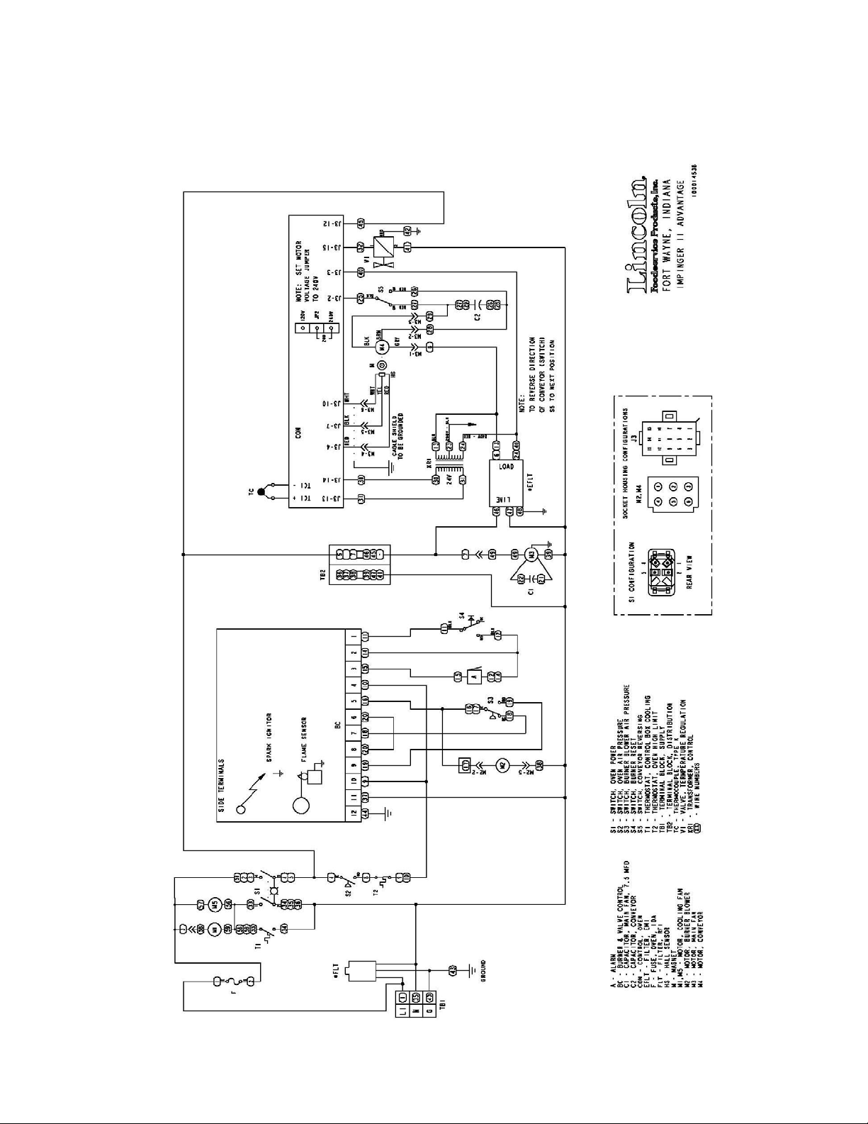
SCHEMATIC DIAGRAM
MODEL SERIES 1154, 1155, 1157, 1158 EXPORT
EXPRESS SERIES
Impinger II – Advantage Digital Express Service Manual - International
5
Page 6
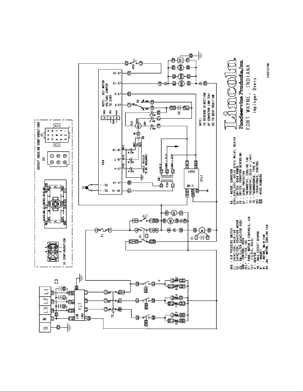
SCHEMATIC DIAGRAM
MODEL SERIES 1164 EXPORT
EXPRESS SERIES
6
Impinger II – Advantage Digital Express Service Manual - International
Page 7
TROUBLESHOOTING GUIDE
IMPINGER II ADVANTAGE DIGITAL EXPRESS
SERIES 1154 EXPORT NAT. GAS 230VAC 50 HZ. 1 PHASE
SERIES 1155 EXPORT LP GAS 230VAC 50 HZ. 1 PHASE
SERIES 1157 EXPORT NAT. GAS 230VAC 50/60HZ 1 PHASE
SERIES 1158 EXPORT LP GAS 230VAC 50/60HZ 1 PHASE
REFER TO PROPER SCHEMATIC FOR IDENTIFIED COMPONENTS
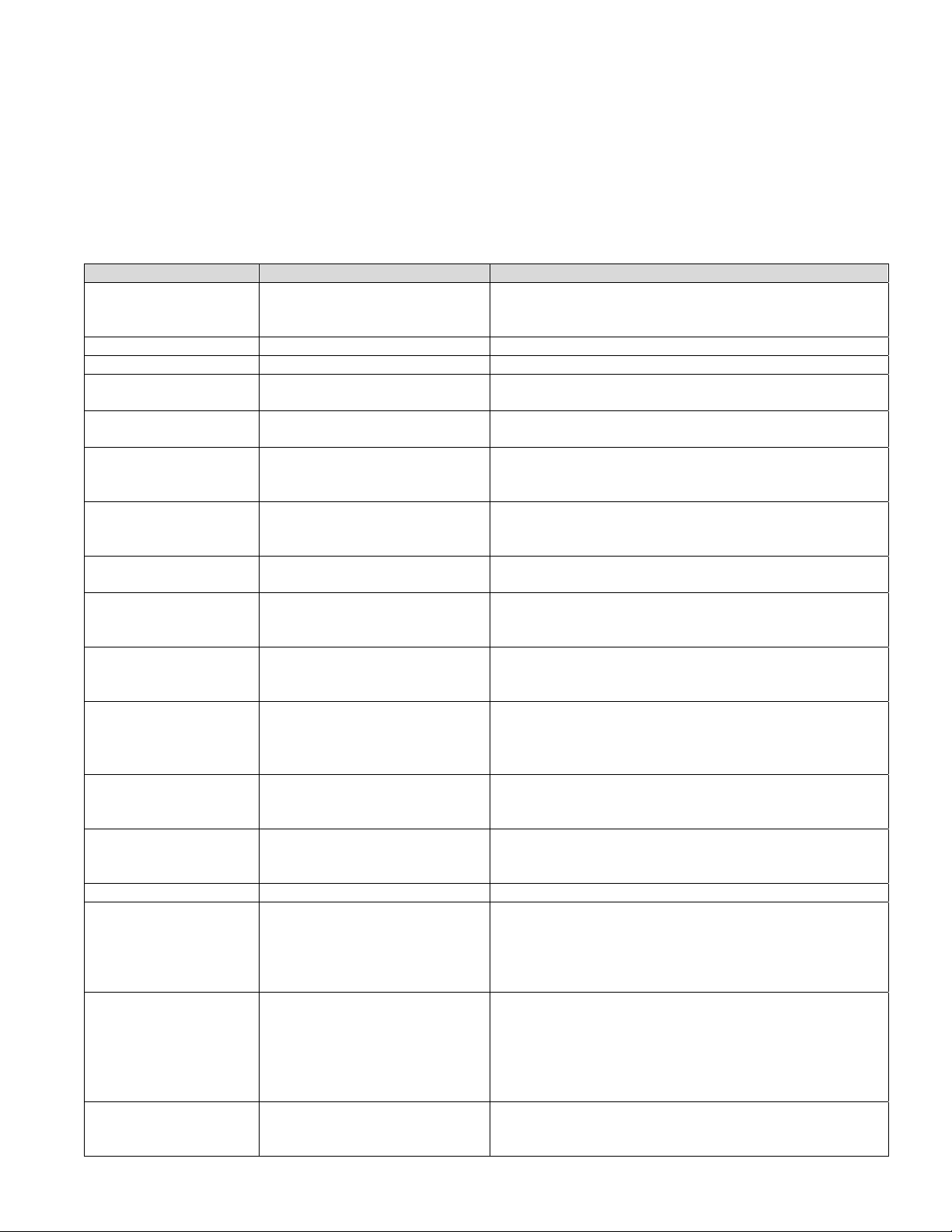
SYMPTOM POSSIBLE CAUSE EVALUATION
Oven fan will not run Incoming power supply Check breaker, reset if required. Check power plug to
be sure it is firmly in receptacle. Measure incoming
power, call power co. if needed.
Fuse, 10 amp Check, replace if necessary.
Fuse holder Check, replace if necessary.
Switch, main fan With power off, check continuity between switch
terminals. Replace as needed.
Motor, main fan Check for opens, shorts or grounds. With power off, turn
fan blade to check for locked rotor.
Capacitor Check for shorts or grounds.
WARNING: Capacitor has a stored charge, discharge
before testing.
No control box cooling Incoming power supply Check breaker, reset if required. Check power plug to
be sure it is firmly in receptacle. Measure incoming
power, call power co. if needed.
Switch, main fan With power off, check continuity between switch
terminals. Replace as needed.
Cooling fan Line voltage should now be at the cooling fan. If voltage
is present, check motor for opens, shorts or grounds.
With power off, check for locked rotor.
No automatic control
box cooling
Cooling fan thermostat Check the cooling fan thermostat (thermostat closes at
Cooling fan Line voltage should now be at the cooling fan. If voltage
Oven will not heat
Main fan If not operating, refer to “Oven fan will not run”.
Air pressure switch Check air switch terminals for supply voltage to
Oven cavity hi-limit thermostat
Ignition control Check for proper supply voltage to ignition control.
Impinger II – Advantage Digital Express Service Manual - International
Incoming power supply Check breaker, reset if required. Check power plug to
be sure it is firmly in receptacle. Measure incoming
power, call power co. if needed.
120°F and opens at 100°F). With the cooling fan
thermostat pre-heated, check for continuity. If
thermostat is open, replace cooling fan thermostat.
is present, check motor for opens, shorts or grounds.
With power off, check for locked rotor.
Gas supply Check for adequate gas supply and be sure that the
manual gas shut off valve is open. Also check flexible
gas line connection.
terminals C and NO. If voltage is present on one side
only, check for air tube blockage or misalignment. If
these are okay, adjust air pressure switch or replace if
necessary.
Terminals are normally closed, opens at 350°C (660°F).
If open, reset and test oven for proper operation. If
thermostat will not hold for maximum oven temperature,
and oven is not exceeding control setting, check for
proper location of capillary bulb in its spring holder. If
above checks are okay, replace hi-limit thermostat.
Check for proper voltage to the burner blower motor.
This can be checked at motor connecting plug terminal
7
Page 8

2 and Neutral. If voltage is present, proceed with next
step, if not, wait 30 seconds, push reset button and try
to restart. If this fails, check wires from burner blower
motor to the ignition control. If the above checks okay,
replace ignition control.
Burner blower motor Chec k for supply voltage to motor. WITH POWER OFF:
Turn blower wheel to check for locked rotor. If supply
voltage is present at motor connecting plug terminal 2
and Neutral, and motor does not run, replace burner
blower motor.
Air pressure switch
(burner blower)
Check for proper supply voltage switching from “NC” to
“NO” on ignition control. Check for air pressure switch
adjustment, air tube blockage or misalignment. If these
adjustments fail, replace air pressure switch.
Ignition control A pre-purge time of 30 to 60 seconds occurs after
burner blower motor starts. Check for high voltage
spark output from the ignition control. If there is no high
voltage spark output, check reset button for ignition
control. If there is still no high voltage output, replace
the ignition control.
Igniter/sensor assembly Check this a s sembly for visible damage. Replace as
needed. If there is no visible damage, check for voltage
supply to igniter/sensor assembly. If there is voltage
supplied to the igniter/sensor, but there is no spark,
replace igniter/sensor assembly.
Gas valve Gas valve should open as the ignition control generates
the high voltage spark. Place manometer on the
pressure tap fitting (located in the gas piping just prior
to the burner manifold) and check for gas pressure. If
valve does not open, check reset button on ignition
control, and all connections for tightness. If there is still
no gas pressure, remove the ignition control from the
gas valve. Check the coils of the gas valve for opens or
shorts. Readings should be as follows, V1 – 2.9K ohms
approx., V2 – 1.3K ohms approx. If these readings are
not achieved, replace gas valve. If these readings are
achieved, replace ignition control.
Flame will not stay on Flame sensor To check for flame sensor operation, connect a digital
multimeter (capable of measuring DC microamps)
between the flame sensor wire and the flame sensor
connection on the ignition control. Sensor current is to
be 0.9 microamps, minimum. If these readings are not
achieved, replace igniter/sensor assembly. Also check
for any type of damage to flame sensor wire and
connections.
NOTE: The DC microamp test must be conducted with
the oven in low flame (bypass) operation.
Power supply Set the temperature to the lowest temperature setting.
If there is sufficient microamp current, but the flame will
not stay lit, check for proper polarity of the power
supply.
Ignition control If there is sufficient microamp current, and there is
proper polarity of the power supply, but the burner will
not stay lit, check the reset button on the ignition
control. If the above test is okay, replace the ignition
control.
NOTE: Flame should be on at
this time
Low flame is on, but
no main flame
Control transformer Check for supply voltage to the primary of control
transformer. If no voltage is present, trace wiring back
to oven fan switch. If voltage is present, check for
8
Impinger II – Advantage Digital Express Service Manual - International
Page 9

24VAC at transformer secondary. If there is primary
voltage, but no secondary voltage, replace control
transformer.
Conveyor motor Check for supply voltage to the conveyor motor at wire
#6 to neutral. If no voltage is present, trace wiring back
to the oven fan switch. If voltage is present, but the
motor will not run, check the motor windings for opens
or shorts. If any of the above fail, replace the conveyor
motor.
Capacitor, conveyor motor Check for shorts or grounds. Replace capacitor as
needed.
WARNING: Capacitor has a stored charge, discharge
before testing.
Switch, conveyor reversing Check continuity between switch terminals. Replace
switch as needed.
Oven control If there is voltage supplied to the motor, and the motor,
capacitor and reversing switch check good, replace the
oven control.
Conveyor motor runs,
but there is no speed
display
Oven control Check for output voltage from oven control to hall effect
Conveyor motor If there is voltage supplied to the hall effect sensor,
Oven control If the hall effect sensor readings are correct, but there
NOTE: Display will indicate
“BELT JAM”
sensor (sensor is located in the conveyor motor).
Measure voltage at the motor connector, red wire and
yellow wire. Voltage should be approx. 10VDC. If no
voltage is present, trace wiring back to oven control. If
there is no voltage output at the oven control, replace
oven control.
check for a frequency output from the hall effect
sensor. Measure frequency across the yellow and white
wires in the motor connector. Frequency reading
should be approx. 25-100 Hz. If these readings are not
achieved, replace conveyor motor. If the readings are
achieved, proceed.
is no speed indicated on the display, replace the oven
control
Impinger II – Advantage Digital Express Service Manual - International
9
Page 10
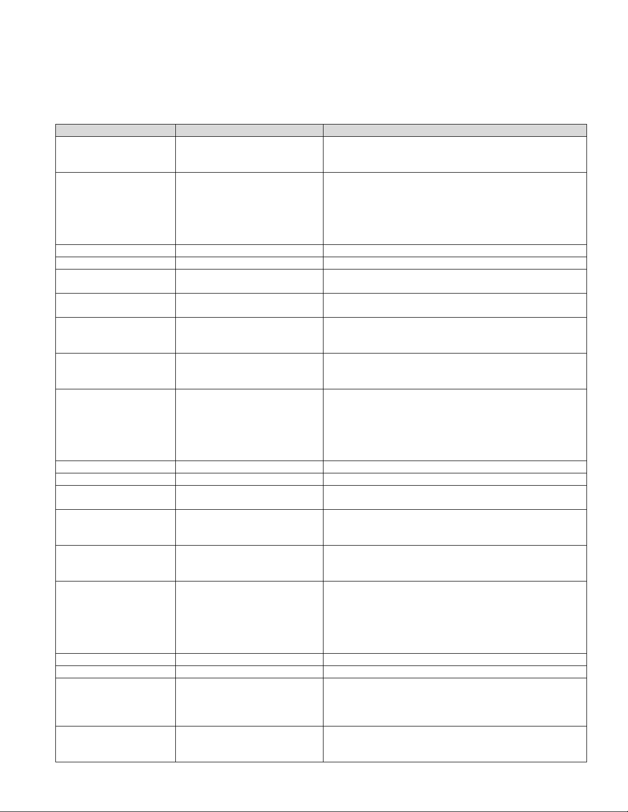
TROUBLESHOOTING GUIDE
IMPINGER II ADVANTAGE DIGITAL EXPRESS
SERIES 1164 EXPORT 400/230VAC 50HZ. 3 PHASE
REFER TO PROPER SCHEMATIC FOR IDENTIFIED COMPONENTS
SYMPTOM POSSIBLE CAUSE EVALUATION
Oven fan will not run Incoming power supply Check breaker, reset if required. Check power plug to
be sure it is firmly in receptacle. Measure incoming
power, call power co. if needed.
No control box cooling Incoming power supply Check breaker, reset if required. Check power plug to
Oven cavity hi-limit
Fuse, 10 amp Check, replace if necessary.
Fuse holder Check, replace if necessary.
Switch, main fan With power off, check continuity between switch
Cooling fan Line voltage should now be at the cooling fan. If voltage
No automatic control
box cooling
Oven cavity hi-limit
Fuse, 10 amp Check, replace if necessary.
Fuse holder Check, replace if necessary.
Cooling fan thermostat Check the cooling fan thermostat (thermostat closes at
Cooling fan Line voltage should now be at the cooling fan. If voltage
10
Oven cavity hi-limit
thermostat
Fuse, 10 amp Check, replace if necessary.
Fuse holder Check, replace if necessary.
Switch, main fan With power off, check continuity between switch
Motor, main fan Check for opens, shorts or grounds. With power off, turn
Capacitor Check for shorts or grounds.
thermostat
Incoming power supply Check breaker, reset if required. Check po wer plug to
thermostat
Impinger II – Advantage Digital Express Service Manual - International
Terminals are normally closed, opens at 660°F (350°C).
If open, reset and test oven for proper operation. If
thermostat will not hold for maximum oven temperature,
and oven is not exceeding control setting, check for
proper location of capillary bulb ion its spring holder. If
above checks are okay, replace hi-limit thermostat.
terminals. Replace as needed.
fan blade to check for locked rotor.
WARNING: Capacitor has a stored charge, discharge
before testing.
be sure it is firmly in receptacle. Measure incoming
power, call power co. if needed.
Terminals are normally closed, opens at 660°F (350°C).
If open, reset and test oven for proper operation. If
thermostat will not hold for maximum oven temperature,
and oven is not exceeding control setting, check for
proper location of capillary bulb in its spring holder. If
above checks are okay, replace hi-limit thermostat.
terminals. Replace as needed.
is present, check motor for opens, shorts or grounds.
With power off, check for locked rotor.
be sure it is firmly in receptacle. Measure incoming
power, call power co. if needed.
Terminals are normally closed, opens at 660°F (350°C).
If open, reset and test oven for proper operation. If
thermostat will not hold for maximum oven temperature,
and oven is not exceeding control setting, check for
proper location of capillary bulb ion its spring holder. If
above checks are okay, replace hi-limit thermostat.
120°F and opens at 100°F). With the cooling fan
thermostat pre-heated, check for continuity. If
thermostat is open, replace cooling fan thermostat.
is present, check motor for opens, shorts or grounds.
With power off, check for locked rotor.
Page 11

Oven will not heat Main fan If not operating, refer to “Oven fan will not run”.
Control transformer Check for supply voltage to the primary of control
transformer. If no voltage is present, trace wiring back
to oven fan switch. If voltage is present, check for
24VAC at transformer secondary. If there is primary
voltage, but no secondary voltage, replace control
transformer.
Air pressure switch Check air switch terminals for supply voltage to
terminals “NO” and “COM”. If voltage is present on one
side only, check for air tube blockage or misalignment.
If these are okay, adjust air pressure switch or replace if
necessary.
Oven control Check for 24VAC supply to oven control. If no voltage is
present, trace wiring back to control transformer. Check
for supply voltage to oven control. If no voltage is
present, trace wiring back to oven fan switch. If voltage
is present, check for a read-out on the display. If there
is no read-out on the oven display, replace oven
display. If there is a read-out on the oven control, set
the control to maximum temperature (see Installation
operation manual for temperature adjustment). With the
control at maximum temperature, check for supply
voltage to the mercury contactor. If there is voltage at
the contactors, proceed to “Mercury contactor” for next
check. If there is no voltage at the mercury contactor,
trace wiring back to the oven control. If there is no
voltage output at the oven control, check the read-out
on the oven control. If the oven control reads “PROBE
FAIL” this indicates that the thermocouple has failed or
become disconnected from the oven control.
Thermocouple Check to see that the thermocouple is securely
connected to the oven control. If the thermocouple is
connected to the oven control, and the display indicates
“PROBE FAIL”, disconnect the thermocouple from the
oven control and measure the resistance of the
thermocouple. The thermocouple should read approx.
11Ω. If these readings are not achieved, replace the
thermocouple. If these readings are correct, proceed.
Oven control If the thermocouple checks good, but the oven control
indicates that there is a thermocouple failure, replace
the oven control. If the oven control indicates a
temperature reading but the oven will not heat,
proceed.
Thermocouple WITH POWER ON AND THERMOCOUPLE
ATTACHED TO THE OVEN CONTROL: Measure the
DC millivolt output of the thermocouple. Refer to the
thermocouple chart (located in the “Removal” section of
the manual) for proper millivolt readings. If these
readings are not achieved, replace thermocouple.
Oven control If the thermocouple checks good, but there is no supply
voltage output to the contactor, replace the oven
control. If there is supply voltage output to the
contactor, proceed.
S.S. Relays Check for supply voltage to the contactor coil. If voltage
is present and the contactor will not activate, replace
the contactor Also check each contactor for high
voltage input and output.
Heating element(s) Check the Amp draw on each power leg for proper
load. Check the specification plate for rating
information. If the Amp draw is high or low, check the
Impinger II – Advantage Digital Express Service Manual - International
11
Page 12

individual elements for opens, shorts and proper
resistance.
WITH POWER OFF; To check resistance of the
elements, remove all leads from the elements and use
a digital multimeter.
The element resistance should be as follows:
230V – 33 ohm.
Replace heating elements as needed.
Oven heats with
switch off
Contactor The contactor has probably failed in the closed position.
If there is no voltage at the operating coil, but there is
high voltage output from the contactor, replace the
contactor.
Intermittent heating Thermal/overload of
main fan motor
The main fan motor is equipped with internal thermal
protection and will cease to operate if overheating
occurs. As the motor overheats and cools, this will
cause the heating system to cycle on and off
intermittently. Improper ventilation or lack of preventive
maintenance may cause this problem. Also, most of the
problem listed under “Oven will not heat” can cause
intermittent failure.
Conveyor will not run
Display reads “belt jam”
Incoming power supply Check breaker, reset if required. Check po wer plug to
be sure it is firmly in receptacle. Measure incoming
power, call power co. if needed.
Fuse, 10 amp Check, replace if necessary.
Fuse holder Check, replace if necessary.
Switch, main fan With power off, check continuity between switch
terminals. Replace as needed.
Control transformer Check for supply voltage to the primary of control
transformer. If no voltage is present, trace wiring back
to oven fan switch. If voltage is present, check for
24VAC at transformer secondary. If there is primary
voltage, but no secondary voltage, replace control
transformer.
Conveyor motor Check for supply voltage to the conveyor motor at wire
#10 to neutral. If no voltage is present, trace wiring
back to the oven fan switch. If voltage is present, but
the motor will not run, check the motor windings for
opens or shorts. If any of the above fail, replace the
conveyor motor.
Capacitor, conveyor motor Check for shorts o r grounds. Replace capacitor as
needed.
WARNING: Capacitor has a stored charge, discharge
before testing.
Switch, conveyor reversing Check continuity between switch terminals. Replace
switch as needed.
Oven control If there is voltage supplied to the motor, and the motor,
capacitor and reversing switch check good, replace the
oven control.
Conveyor motor runs,
but there is no speed
control
Oven control Check for output voltage from oven control to hall effect
sensor (sensor is located in the conveyor motor).
Measure voltage at the motor connector, red wire and
yellow wire. Voltage should be approx. 10VDC. If no
voltage is present, trace wiring back to oven control. If
there is no voltage output at the oven control, replace
oven control.
Conveyor motor If there is voltage supplied to the hall effect sensor,
check for a frequency output from the hall effect sensor.
Measure frequency across the yellow and white wires in
the motor connector. Frequency reading should be
approx. 25-100 Hz. If these readings are not achieved,
12
Impinger II – Advantage Digital Express Service Manual - International
Page 13

replace conveyor motor. If the readings are achieved,
proceed.
Oven control If the hall effect sensor readings are correct, but there is
no speed indicated on the display, replace the oven
control
Impinger II – Advantage Digital Express Service Manual - International
13
Page 14

REMOVAL, INSTALLATION AND ADJUSTMENTS
IMPINGER II ADVANTAGE DIGITAL EXPRESS SERIES
CAUTION
BEFORE REMOVING OR INSTALLING ANY COMPONENT IN THE IMPINGER
OVEN BE SURE TO DISCONNECT ELECTRICAL POWER AND GAS SUPPLY.
MAIN FAN – REPLACEMENT
A. Shut off power at main breaker.
B. Remove motor cover from back of oven.
C. Disconnect wiring and mark for reassembly.
D. Remove bolts and slide back straight out of the oven.
E. Loosen the bolt from fan hub and remove fan from motor shaft.
NOTE: Measure distance from fan blade to rear wall assembly before removal to aid in reassembly.
F. Reassemble in reverse order and check system operation.
MOTOR, MAIN FAN – REPLACEMENT
A. Shut off power at main breaker.
B. Remove motor cover from back of oven.
C. Disconnect wiring and mark for reassembly.
D. Remove bolts and slide back straight out of the oven.
E. Loosen the bolt from fan hub and remove fan from motor shaft.
NOTE: Measure distance from the fan blade to rear wall assembly before removal to aid in reassembly.
F. Remove four screws from motor support assembly.
G. Remove motor mount clamp and remove motor from oven back.
H. Remove motor mount from motor.
I. Reassemble in reverse order and check system opera t ion.
CAPACITOR – REPLACEMENT
A. Shut off power at main breaker.
B. Remove control box cover and front panel.
C. Discharge capacitor.
D. Remove capacitor.
E. Reassemble in reverse order and check system operation.
ON/OFF SWITCH – REPLACEMENT
A. Shut off power at main breaker.
B. Remove control box cover and front panel.
C. Depress spring clips on sides of switch and push out.
D. Remove wires from switch and mark for reassembly.
E. Reassemble in reverse order and check system operation.
NOTE: Make sure switch housing is fully seated in control box housing.
14
Impinger II – Advantage Digital Express Service Manual - International
Page 15

FUSE HOLDER – REPLACEMENT
A. Shut off power at main breaker.
B. Remove control box cover and front panel.
C. Remove wires from fuse holder and mark for reassembly.
D. Remove mounting screws or mounting nut on fuse holder and remove fuse holder.
E. Reassemble in reverse order and check system operation.
COOLING FAN, CONTROL BOX – REPLACEMENT
A. Shut off power at main breaker.
B. Remove control panel top and front cover.
C. Remove four mounting screws from fan frame.
D. Disco nnect power cord and remove fan.
E. Reassemble in reverse order and check system operation.
THERMOSTAT, COOLING FAN, REPLACEMENT
A. Shut off power at main breaker.
B. Remove control panel top and front cover.
C. Remove wires and mark for reassembly.
D. Remove two mounting screws and remove thermostat.
E. Reassemble in reverse order and check system operation.
NOTE: Push reset button on new thermostat.
BURNER BLOWER MOTOR – REPLACEMENT
A. Shut off power at main breaker.
B. Remove control panel top and front cover.
C. Unplug motor connector.
D. Remove three mounting screws from blower tube at burner housing.
E. Remove air shutter assembly from old motor for assembly on new motor.
F. Reassemble in reverse order and check system operation.
NOTE: Check air shutter at approximately ½ open and adjust to get a blue flame with an occasional tip of
yellow under high flame. A view port in the burner assembly should be used to observe flame.
HI-LIMIT THERMOSTAT, OVEN CAVITY – REPLACEMENT
A. Shut off power at main breaker.
B. Remove conveyor and bottom finger assembly.
C. Remove capillary bulb from bracket in oven chamber and pull capillary tube through tube into control
box.
D. Remove all wires and mark for reassembly.
E. Remove mounting nut and remove thermostat.
F. Reassemble in reverse order and check system operation. Be sure capillary tube is securely in the
mount.
NOTE: Push reset button on new thermostat.
Impinger II – Advantage Digital Express Service Manual - International
15
Page 16

TRANSFORMER, CONTROL – REPLACEMENT
A. Shut off power at main breaker.
B. Remove control panel top and front cover.
C. Remove all wires from transformer and mark for reassembly.
D. Remove two mounting screws from transformer base and remove transformer.
E. Reassemble in reverse order and check system operation.
OVEN CONTROL – REPLACEMENT (2 pcs.)
A. Shut off power at main breaker.
B. Remove control box cover and front panel.
C. Remove all wiring connections and mark for reassembly.
D. Remove oven control by pulling control from the mounting pins. Remove control from oven.
E. Before installing new oven control, set voltage jumper (located at the bottom center of the oven
control) to the proper voltage (120V/240V) position. Install the four pushbutton extensions
(included with the oven control) by pushing the extensions onto the four set buttons on control.
F. Reassemble in reverse order and check system operation.
G. Set the oven control for the proper operating mode. The 1100 series ovens use a single temperature
control system. The oven control must be set to the proper operating mode. Set the control as
follows: With the oven power switch “off”, depress the “time” and “up” buttons and turn the oven “on”.
Control will indicate ”Imp I or Imp II”. Release the buttons, The control will indicate “Temp to store”.
Press the “up” or “down” until ”Imp II” appears on the display. Press the “temp” button. The control is
now set for single burner operation.
THERMOCOUPLE – REPLACEMENT
A. Shut off power at main breaker.
B. Remove conveyor and bottom finger assembly.
C. Remove control panel top and front cover.
D. Remove ther mocouple from bracket in oven chamber and pull thermocouple through tube into control
box.
E. Remove two thermocouple wires from temperature control. Note wire color and location for
reassembly
F. Reassemble in reverse order and check system operation
THERMOCOUPLE MEASUREMENT
TEMPERATURE (°F) TEMPERATURE (°C) D.C. MILLIVOLTS
200° 93° 2.8
250° 121° 4.0
300° 149° 5.1
350° 177° 6.0
400° 204° 7.1
450° 232° 8.2
500° 260° 9.3
550° 288° 10.4
600° 316° 11.5
BURNER CONTROL – REPLACEMENT (S/N2045408 and Above)
A. Shut off power at main breaker.
B. Remove control panel top and front cover.
C. Remove wires from control and mark for reassembly.
D. Remove one mounting screw and remove burner control from the gas valve.
E. Reassemble in reverse order and check system operation.
16
Impinger II – Advantage Digital Express Service Manual - International
Page 17

GAS VALVE – REPLACEMENT (S/N 2045408 and Above)
A. Shut off power at main breaker.
B. Shut off gas supply to the oven and disconnect the flexible gas line to the oven.
C. Remove control panel top and front cover.
D. Remove the manual gas shut off valve.
E. Remove screws from the bulkhead plate on inlet gas pipe and remove inlet gas pipe.
F. Remove wiring from ignition control (mounted on gas valve) mark all wiring for reassembly.
G. Remove pilot tube, Disconnect pipe union in gas line and remove gas valve and piping assembly.
H. Remove piping from gas valve.
I. Reassemble in reverse order and check system opera t ion.
J. Check all gas line fittings for leaks.
K. Adjust the gas manifold pressure on the gas valve. Refer to the specification plate on the oven for
proper rating.
TEMPERATURE REGULATION VALVE – REPLACEMENT
A. Shut off power at main breaker.
B. Shut off gas supply to the oven and disconnect the flexible gas line to oven.
C. Remove control panel top and front cover.
D. Remove bypass tube from burner manifold.
E. Remove wiring from valve and mark for reassembly.
F. Remove four mounting nuts from burner manifold and disconnect pi pe union.
G. Remove temperature regulation valve and piping from oven.
IGNITER/SENSOR ASSEMBLY – REPLACEMENT
A. Shut off power at main breaker.
B. Shut off gas supply to oven.
C. Remove control panel top and front cover.
D. Remove gas valve assembly.(see “GAS VALVE”)
E. Remove temperature regulation valve. (see “TEMPERATURE REGULATION VALVE”)
F. Disconnect all wires from burner and ma rk for reassembly.
G. Remove screws from burner tube and remove burner venturi.
H. Remove two mounting screws and remove igniter/sensor assembly from burner venturi.
I. Reassemble in reverse order and check system operation. Check all gas line fittings for leaks.
BYPASS ORIFICE – REPLACEMENT
A. Shut off power at main breaker.
B. Shut off gas supply to the oven and disconnect the flexible gas line to oven.
C. Remove control panel top and front cover.
D. Disconnect bypass tube from gas valve.
E. Remove bypass orifice from gas valve.
F. Reassemble in reverse order and check system operation.
G. Check all gas line fittings for leaks.
MAIN BURNER ORIFICE – REPLACEMENT
A. Shut off power at main breaker.
B. Shut off gas supply to the oven and disconnect the flexible gas line to oven.
C. Remove control panel top and front cover.
D. Remove burn er manifold. See “TEMPERATURE REGULATION VALVE”.
E. Remove main burner orifice from burner manifold.
F. Reassemble in reverse order and check system operation.
G. Check all gas line fittings for leaks.
Impinger II – Advantage Digital Express Service Manual - International
17
Page 18

REVERSING SWITCH – REPLACEMENT
A. Shut off power at main breaker.
B. Remove control panel top and front cover.
C. Remove wires from reversing switch and mark for reassembly.
D. Remove mounting nut and remove switch.
E. Reassemble in reverse order and check system operation.
CONVEYOR DRIVE MOTOR – REPLACEMENT
A. Shut off power at main breaker.
B. Remove control panel top and front cover.
C. Disconnect all wiring from motor and mark for reassembly.
D. Remove coupling from motor drive shaft.
E. Remove four screws and remove conveyor motor and mounting bracket.
F. Remove mounting bracket from conveyor motor.
G. Reassemble in reverse order and check system operation.
REVERSING CONVEYOR DIRECTION
A. Shut off power at oven switch.
B. Set conveyor reversing switch in the other position.
C. Turn oven “on” and check for proper operation.
CAPACITOR, CONVEYOR DRIVE MOTOR – REPLACEMENT
A. Shut off power at main breaker.
B. Remove control panel top and front cover.
C. Discharge capacitor before removing wires. Mark wires for reassemb ly .
D. Remove m ounting screw and remove capacitor.
E. Reassemble in reverse order and check system operation.
AIR PRESSURE SWITCH – REPLACEMENT
A. Shut off power at main breaker.
B. Remove control panel top and front cover.
C. Disconnect wiring from air pressure switch and mark for reassembly.
D. Disconnect air tube from air pressure switch.
E. Remove two mounting screws and remove air pressure switch.
F. Reassemble in reverse order and check system operation. Be sure to calibrate new air pressure
switch. For proper calibration, see below.
G. Turn adjusting screw on air pressure switch fully counter clockwise.
H. Turn ove n “on”.
I. Turn adjusting screw on air pressure switch clockwise until heat shuts off.
J. Turn adjusting screw on air pressure switch counter clockwise ¼ turn.
K. Reassemble control panel top and front cover.
BEARING, CONVEYOR – REPLACEMENT
A. Remove conveyor from oven and place on a flat work surface.
B. Remove connecting links from conveyor belt. See Installation Operations manual for proper
procedure. Remove conveyor belt from conveyor.
C. Move drive shaft or idler shaft toward end of conveyor, and shaft with bearing will now slip out of
conveyor frame.
D. Remove bearing from conv eyor shaft.
E. Reassemble in reverse order and check system operation.
18
Impinger II – Advantage Digital Express Service Manual - International
Page 19

S.S. RELAYS – REPLACEMENT
A. Shut off power at main breaker.
B. Remove control panel top and front cover.
C. Disconnect all wires and mark for reassembly.
D. Remove screws from mounting bracket and remove contactor.
E. Reassemble in reverse order and check system operation.
HEATING ELEMENT – REPLACEMENT
A. Shut off power at main breaker.
B. Remove back cover.
C. Disconnect heating element wires and mark for reassembly.
D. Disco nnect motor wiring and mark for reassembly.
E. Remove oven back from oven.
F. Remove fan shroud.
G. Heating element may now be unbolted and removed.
H. Check new heating element for proper voltage. Reassemble in reverse order and check for proper
operation.
Impinger II – Advantage Digital Express Service Manual - International
19
Page 20

* A new stand was designed and implemented on March 16, 2009. Parts are not compatible between old
and new stand styles. See Addendum A in the back of this manual for a parts breakdown and assembly
instructions.
IMPINGER II ADVANTAGE DIGITAL EXPRESS
GENERAL VIEW
LETTER PART NUMBER DESCRIPTION
A* 370412 Cross support
B* 370416 Stand side
C* 369231 Caster, 4” w/threaded stem
D* 369232 Adjustable leg
E 369390 Caster, 4” w/mounting plate
F Oven door, See “Conveyor / Door” Section
G 370010 Bottom finger housing
H 369502 Bottom finger cover
I 369504 Top finger housing (model ending with –080-A)
370487 Top finger housing (model ending with –080-A1)
J 369503 Top finger cover (model ending with –080-A)
370486 Top finger cover (model ending with –080-A1)
K 370415 Oven top
L 370679 Conveyor hole cover
M 371066 Baffle
N 369211 Thumb screw
O
P
Columnating plate, see Installation & Operations
manual
Columnating plate, see Installation & Operations
manual
20
Impinger II – Advantage Digital Express Service Manual - International
Page 21

GENERAL VIEW
Impinger II – Advantage Digital Express Service Manual - International
21
Page 22

IMPINGER II ADVANTAGE DIGITAL EXPRESS
1154, 1155, 1157, 1158 SERIES
LETTER PART NUMBER DESCRIPTION
A 357067 Hi Limit Switch
B 369771 Switch Assembly
C 390129 J-Box Cover
D 370117 Terminal Block, 5 Pole
E 370178 Junction Box
F 9003551 10 Amp Fuse Adapter Assembly
G 4071234 Beaded Ferrule
H 369192 Capacitor
I 369378 Fan Motor
J 369507 Thermostat
K 370241 Transformer
L 369125 Terminal Block, 2 Pole
M 9004238 RFI Filter Assembly
N 370682 Capacitor 450V
O 370387 EMI Filter
P 9005479 See 1154 Conveyor Motor Assembly Section
Q 370417 Main Control Board
R
Not Shown 340034 Finger Guard
Not Shown 369579 Alarm
Not Shown 370364 Ground Lug
Not Shown 369432 On/Off Switch
Not Shown 370408 Control Facia
Not Shown 370417 Control Board
Not Shown 370409 Digital Display
Not Shown 370673 Air Pressure Switch
9004480 Stand Off Plate Assy. (S/N 0903210000317 & Below)**
369856 Stand Off Support (S/N 0903210000318 & Above)**
** This pertains to all units non-TU units.
CONTROL BOX
22
Impinger II – Advantage Digital Express Service Manual - International
Page 23

IMPINGER II ADVANTAGE DIGITAL EXPRESS
CONTROL BOX
1154 SERIES, 1155 SERIES
A
B
C
D
K
I
J
H
L
G
E
F
M
N
O
Q
R
Impinger II – Advantage Digital Express Service Manual - International
P
23
Page 24

IMPINGER II ADVANTAGE DIGITAL EXPRESS
BURNER ASSEMBLY, NAT. GAS
1154 SERIES, 1157 SERIES
LETTER PART NUMBER DESCRIPTION
A 369556 Nat. Bypass Orifice .061/1.55mm
B 370401 Ignitor Module, Plug-In
C 370400 Valve, VK4115 A 1000
D 369582 Burner Assembly, Nat. Gas Export
E 370186 Valve, 85294101
F 369401 Air Shutter Assembly
G 369589 Burner Blower Motor
H 370397 Ignitor, Sensor Assembly
I 369654 Venturi, Nat. Gas
J 369901 Manifold, Burner
K 369689 Plug, Pressure Test
L 370036 Main Orifice, Nat.
M 370186 Solenoid Valve
N 369556 Bypass Orifice, Nat.
IMPINGER II ADVANTAGE DIGITAL EXPRESS
BURNER ASSEMBLY, LP GAS
1155 SERIES, 1158 SERIES
LETTER PART NUMBER DESCRIPTION
A 369557 LP Bypass Orifice .0374/0.95mm
B 370401 Ignitor Module, Plug-In
C 370400 Valve, VK4115 A 1000
D 4071136 Burner Assembly, LP Export
E 370186 Valve, 85294101
F 369401 Air Shutter Assembly
G 369589 Burner Blower Motor
H 370397 Ignitor, Sensor Assembly
I 369939 Venturi, LP Gas
J 369901 Manifold, Burner
K 369689 Plug, Pressure Test
L 369524 Main Orifice, LP
M 370186 Solenoid Valve
N 369557 Bypass Orifice, LP
24
Impinger II – Advantage Digital Express Service Manual - International
Page 25

IMPINGER II ADVANTAGE DIGITAL EXPRESS
BURNER ASSEMBLY
E
A
B
C
D
F
G
I
N
M
H
L
K
J
Impinger II – Advantage Digital Express Service Manual - International
25
Page 26

IMPINGER II ADVANTAGE DIGITAL EXPRESS
CONVEYOR MOTOR ASSEMBY
ALL MODELS
LETTER PART NUMBER DESCRIPTION
A 370676 Conveyor Motor
B 370686 Conveyor Motor Bracket
C 370671 Coupling
26
Impinger II – Advantage Digital Express Service Manual - International
Page 27

C
IMPINGER II ADVANTAGE DIGITAL EXPRESS
CONVEYOR MOTOR ASSEMBY
ALL MODELS
B
A
Impinger II – Advantage Digital Express Service Manual - International
27
Page 28

IMPINGER II ADVANTAGE DIGITAL EXPRESS
CONTROL BOX
1164 SERIES
LETTER PART NUMBER DESCRIPTION
A 370672 50 Amp Solid State Relay
B 370674 Surge Protector
C 370117 Terminal Block, 5 Pole
D 390129 J-Box Cover
E 10002030 Line Filter
F 369192 Capacitor
G 9005478 See 1164 Conveyor Motor Assembly Section
H 370417 Main Control Board
I 369507 Thermostat
J 370673 Air Switch
K 369368 Hi Limit Thermostat
L 370682 Capacitor
M 370387 EMI Filter
N 369378 Fan Motor
O 370241 Transformer
Not Shown 340034 Finger Guard
Not Shown 370364 Ground Lug
Not Shown 369432 On/Off Switch
Not Shown 370408 Control Facia
Not Shown 370417 Control Board
Not Shown 370409 Digital Display
Not Shown 370673 Air Pressure Switch
28
Impinger II – Advantage Digital Express Service Manual - International
Page 29

IMPINGER II ADVANTAGE DIGITAL EXPRESS
CONTROL BOX
1164 SERIES
A
B
C
I
H
G
F
E
D
J
K
L
O
N
Impinger II – Advantage Digital Express Service Manual - International
M
29
Page 30

OVEN BACK ASSEMBLY
ALL MODELS
LETTER PART NUMBER DESCRIPTION
A 369182 Fan
B 369899 Fan shroud
C 369655 Stand off
D 370164 Heating Element – 1164 Only
369549 Rear Wall - 1164
E
F 369581 Motor mount
G 369196 Motor – 1154, 1155, 1164
369181 Motor – 1157, 1158
H 369695 Bracket, motor
I 369033 Clamp, motor
J 369681 Cover, back
K 369979 Bracket, hi-limit
L 369227 Spring
M 369541 Bracket, thermocouple
369976 Rear Wall – 1154, 1155
369976 Rear Wall – 1157, 1158
30
Impinger II – Advantage Digital Express Service Manual - International
Page 31

OVEN BACK ASSEMBLY
ALL MODELS
Impinger II – Advantage Digital Express Service Manual - International
31
Page 32

CONVEYOR / DOOR
ALL MODELS
LETTER PART NUMBER DESCRIPTION
A -- -B -- -C -- -D -- -E 369223 Crumb pan, right and left
F 369223 Crumb pan, right and left
G 369666 Conveyor frame assembly
H 369226 Pan stop
J 369516 Conveyor bearing
K 369514 Idler shaft
369515 Sprocket (includes set screw), Regular Conveyor
L
M 370678 Drive shaft
N 369513 Hinge
O 370413 Door assembly
P 370016 Impinger nameplate
Q 369501 Door latch & catch
R 370414 Door assembly with window
S 369927 Window frame, top
T 369925 Glass, access window
U 369926 Window frame, bottom
W 369929 Retainer, window
X 369165 Splice clip, conveyor belt
Y
Not Shown 369471 Roll Pin
369978 Set screw
370509 Sprocket (includes set screw), Heavy-Duty Conveyor
369194 Conveyor belt (complete), Regular Conv eyor
369394 Conveyor belt (1-Foot section), Regular Conveyor
370155 Conveyor Belt (complete), Heavy-Duty Conveyor
370157 Conveyor Belt (1-Foot Section), Heavy-Duty Conveyor
32
Impinger II – Advantage Digital Express Service Manual - International
Page 33

CONVEYOR / DOOR
Impinger II – Advantage Digital Express Service Manual - International
33
Page 34

STAINLESS STEEL ACCESS DOOR
ALL MODELS (SN 0908210000875 AND ABOVE)
LETTER PART NUMBER DESCRIPTION
369110 Access Door Assembly
A 371140 Bracket Assembly, Left
B 371142 Dowel, Access Door
C 370722 Screw
D 371143 8-32 x 3/8 Hx Serr Flng
E 371141 Bracket Assembly, Right
F 370725 Dowel Thread
G 371144 Access Door Frame (top or bottom)
H 370723 Glass
H
A
B
C
D
E
G
F
34
Impinger II – Advantage Digital Express Service Manual - International
Page 35

ADDENDUM A
NEW STYLE OVEN STAND (BEGINNING MARCH 16, 2009)
1. Insert the four Stand Side Bars (G) into the four holes located on each of the Front/Back Assemblies (A). Note: The Stand Side Bar that
contains labels should be facing “out” so that the labels can be easily read by the operator.
2. Attach the Stand Side Bars to the Front/Back Assemblies and tighten using the 1 ¾” Hexagon Bolts (B), Washers (E) and Acorn Nuts (D) provided.
Two sets each of the bolts, washers and nuts are to be used at each intersection of Stand Side Bars and Front Back Assemblies for a total of 16
sets.
3. Select Caster or Adjustable Leg and screw into nutsert in the bottom corner of each Front/Back Stand Assembly. Tighten Casters securely.
4. Set assembled Stand on casters/legs in an open, clear area and lock casters, as applicable, in preparation for mounting oven on stand.
5. When placing the oven on the stand, align the bolt holes located in the Front/Back Stand Assemblies with the holes located in the bottom of the
oven. With holes in alignment, insert the 2 ½” Hexagon Bolts and tighten to secure the oven to Stand (Fig. 2).
!
CAUTION:
USE EXTREME CARE IN STEP #5 TO INSURE OVEN DOESN’T SLIP OFF STAND BEFORE BOLTS HAVE
SECURED OVEN TO STAND.
HARDWARE PROVIDED FOR STAND ASSEMBLY
LETTER PART # DESCRIPTION
A 90000799 Front / Back Stand Assemblies
B 000151SP Hexagon Bolt (1 ¾”)
C 369231 Caster, 4”
D 2133001 Acorn Nut
E 000821SP Washer
F 369233 Hexagon Bolt (2 ½” )
G 10004656 Stand Side Bar
H Adjustable Leg for 1127-1 stand
Not Shown 9002533
Not Shown Hexagon Bolt (1/2”) for double-stack oven configuration
G
Shelf for 1127-1 stand
F
A
E
D
C
Impinger II – Advantage Digital Express Service Manual - International
B
H
35
Page 36

Lincoln Foodservice Products, LLC
1111 North Hadley Road
Fort Wayne, Indiana 46804
Telephone: 260.459.8200
Fax: 260.436.0735
Technical Support: 260.459.8200
lincolnfp.com
36
Impinger II – Advantage Digital Express Service Manual - International
 Loading...