

Page 1

SERVICE MANUAL
(DOMESTIC)
IMPINGER CONVEYOR OVENS
MODEL 1100 SERIES
Lincoln Foodservice Products, LLC
1111 North Hadley Road
Fort Wayne, Indiana 46804
United States of America
Phone : (260) 459-8200
U.S. Fax: (888) 790-8193 • Int’l Fax: (260) 436-0735
Technical Service Hot Line
(800) 678-9511
www.lincolnfp.com
1100svcdom REV 11/4/08
Page 2

TABLE OF CONTENTS
SEQUENCE OF OPERATIONS 1100 thru 1103 .....................................................................................................3
SEQUENCE OF OPERATIONS 1116 - 1117 ..........................................................................................................4
SEQUENCE OF OPERATIONS 1130 - 1133 & 1160 - 1163................................................................................... 6
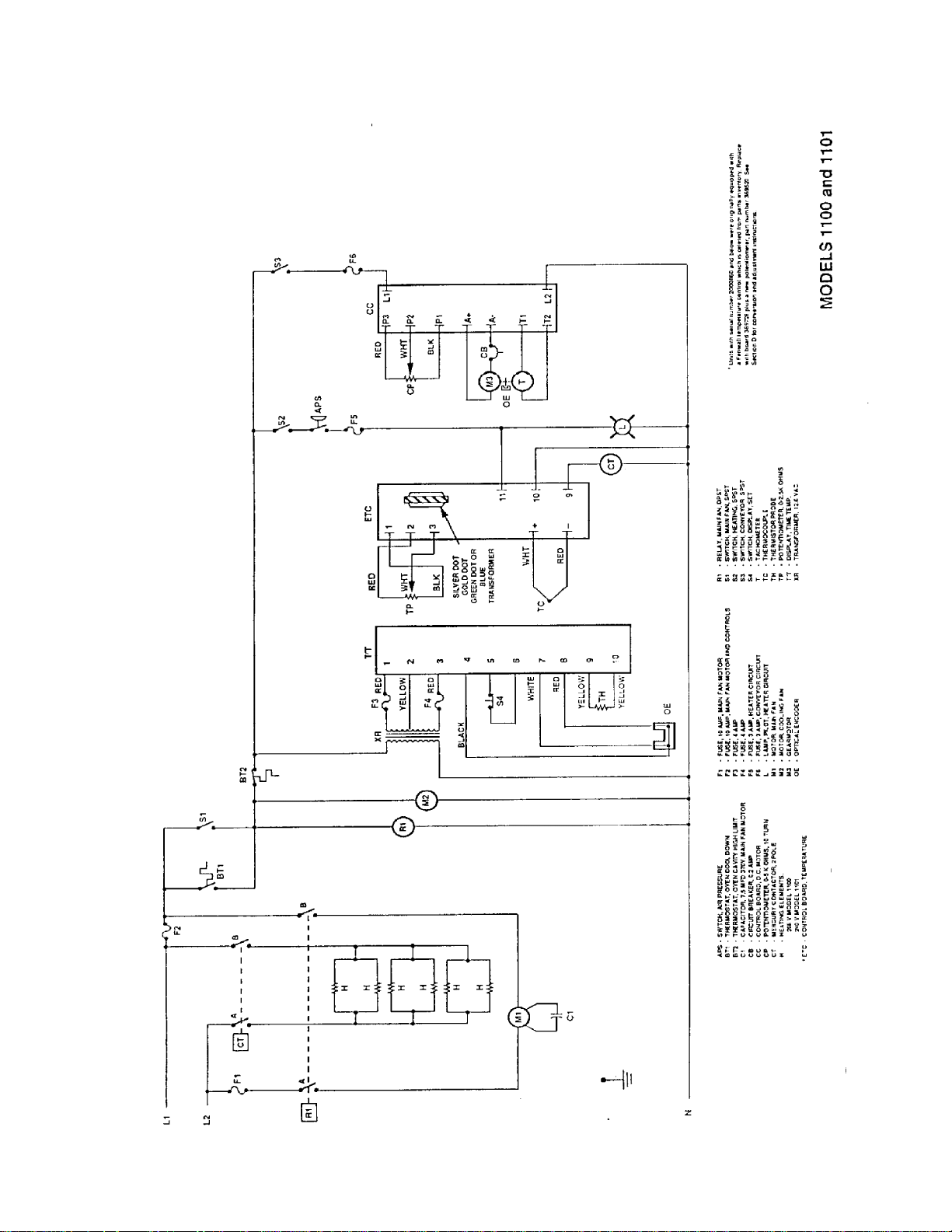
SCHEMATIC 1100 – 1101 .......................................................................................................................................8
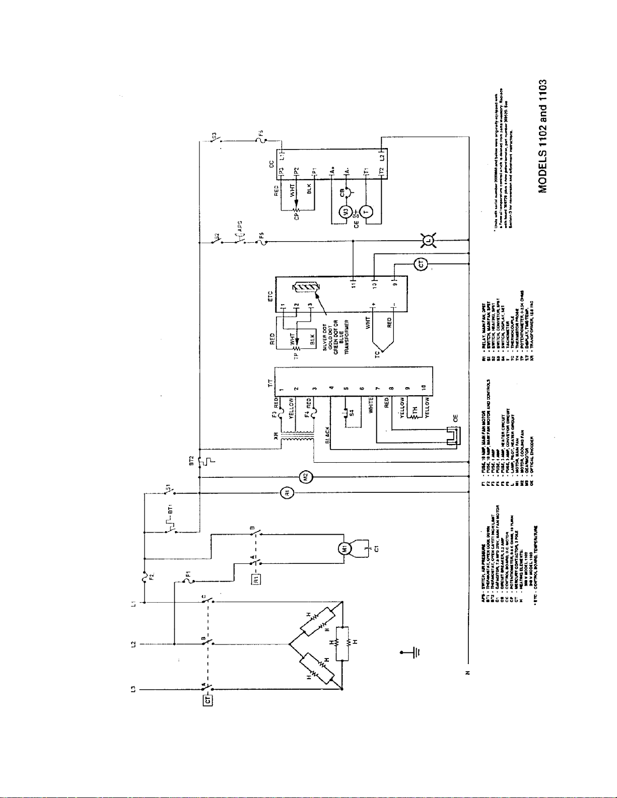
SCHEMATIC 1102-1103 ..........................................................................................................................................9
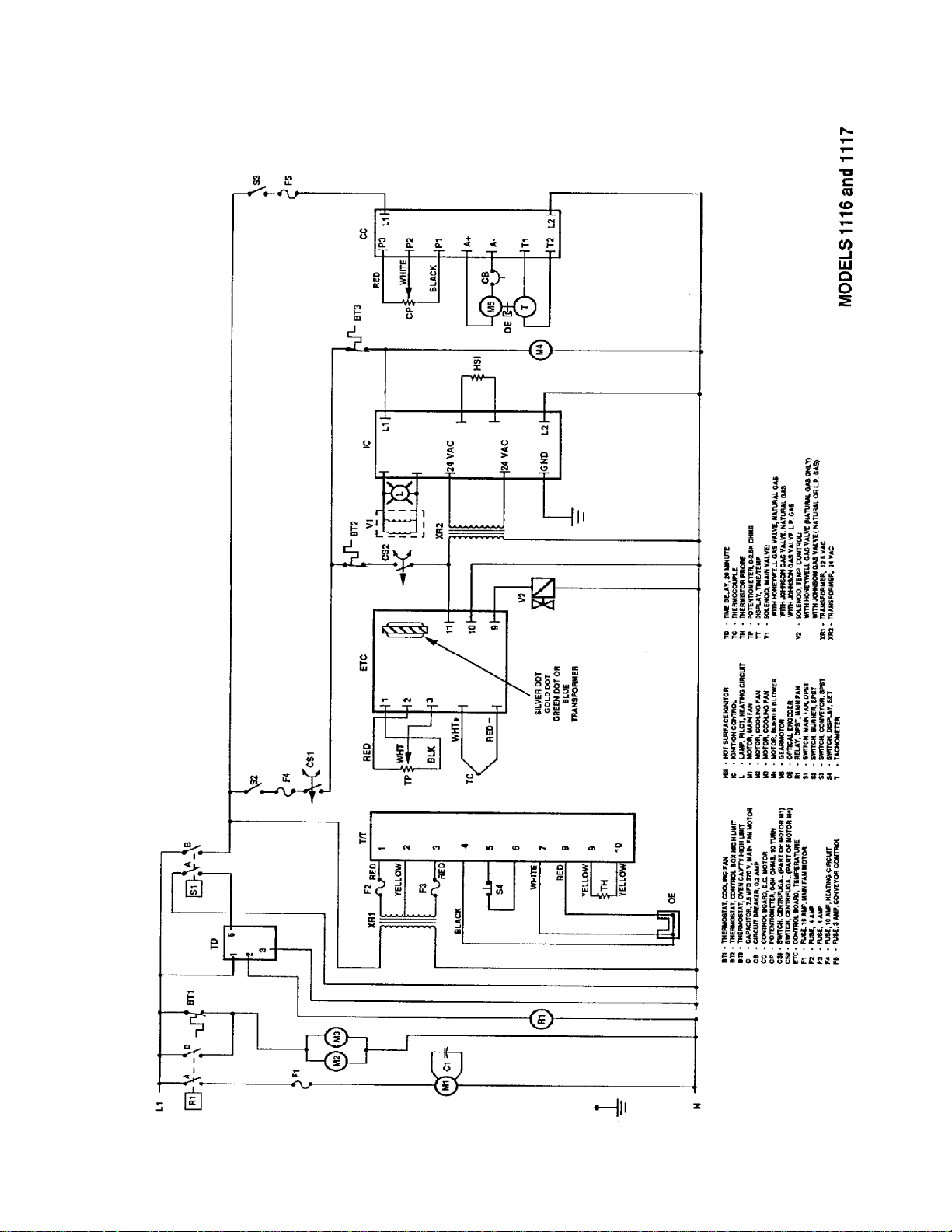
SCHEMATIC 1116 – 1117 S/N 2011383 & BELOW.............................................................................................. 10
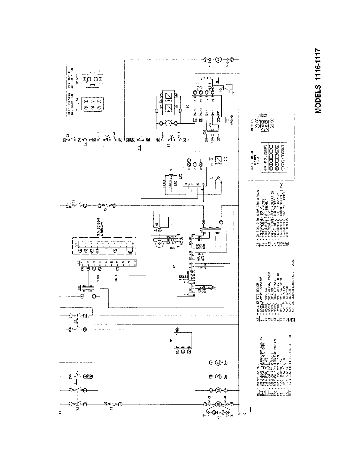
SCHEMATIC 1116 – 1117 S/N 2011384 & ABOVE ..............................................................................................11
SCHEMATIC 1130 – 1131 S/N 2011383 & BELOW & 1160 – 1161 S/N 2011978 & BELOW..............................12
SCHEMATIC 1130 – 1131 S/N 2011384 & ABOVE ..............................................................................................13
SCHEMATIC 1160 – 1161 S/N 2011978 & ABOVE ..............................................................................................14
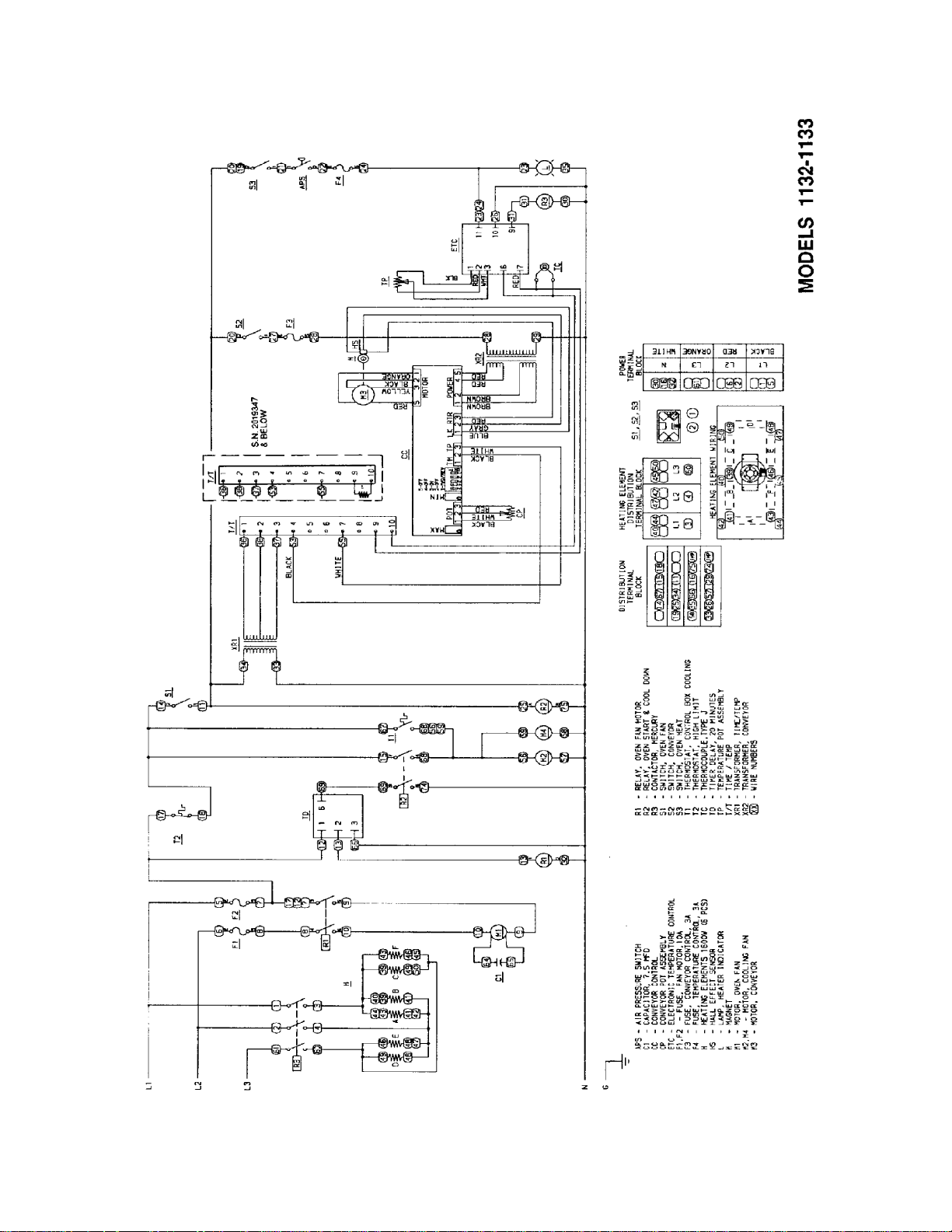
SCHEMATIC 1132 – 1133 S/N 2011383 & BELOW & 1162 – 1163 S/N 2011979 & BELOW..............................15
SCHEMATIC 1132 – 1133 S/N 2011384 & ABOVE ..............................................................................................16
SCHEMATIC 1162 – 1163 S/N 2011978 & ABOVE ..............................................................................................17
TROUBLESHOOTING GUIDE 1116 - 1117........................................................................................................... 18
TROUBLESHOOTING GUIDE 1100 THRU 1103..................................................................................................22
TROUBLESHOOTING GUIDE 1130 THRU 1133 / 1160 THRU 1163................................................................... 24
REMOVAL, INSTALLATION, AND ADJUSTMENT ...............................................................................................31
PARTS / GENERAL –1100 SERIES ......................................................................................................................50
BLOW UP / GENERAL – 1100 SERIES.................................................................................................................51
PARTS / CONTROL COMPARTMENT FRONT 1100 - 1106, 1130 - 1136, 1150,1151,1160 – 1163 ..................52
BLOW UP / CONTROL COMPARTMENT FRONT 1100 – 1106,1130 – 1136, 1150,1151,1160 – 1163 ............. 53
PARTS / CONTROL. COMPARTMENT FRONT 1116,1117 .................................................................................54
BLOW UP / CONTROL COMPARTMENT FRONT 1116, 1117............................................................................. 55
PARTS / CONTROL COMPARTMENT REAR 1100 – 1106, 1130 – 1136, 1150,1151, S/N 2011373 & BELOW, 1160
– 1163 S/N 2011978 & BELOW .............................................................................................................................56
BLOW UP / CONTROL COMPARTMENT REAR 1100 – 1106, 1130 – 1136, 1150,1151, S/N 2011373 & BELOW,
1160 – 1163 S/N 2011978 & BELOW ....................................................................................................................57
PARTS / CONTROL COMPARTMENT REAR 1130 - 1136, 1150, 1151, S/N2011383 AND ABOVE, 1160 – 1163 S/N
3011978 AND ABOVE............................................................................................................................................ 58
BLOW UP / CONTROL COMPARTMENT REAR 1130 - 113
S/N 3011978 AND ABOVE.....................................................................................................................................59
PARTS / CONTROL COMPARTMENT REAR 1116, 1117, S/N 2000200 TO 2011383 .......................................60
BLOW UP / CONTROL COMPARTMENT REAR 1116, 1117, S/N 2000200 TO 2011383................................... 61
PARTS / CONTROL COMPARTMENT REAR 1116, 1117 S/N 2011383 & ABOVE ............................................62
BLOW UP / CONTROL COMPARTMENT REAR 1116, 1117 S/N 2011383 & ABOVE ........................................ 63
PARTS / OVEN BACK ASSEMBLY 1100 SERIES................................................................................................64
BLOW UP / OVEN BACK ASSEMBLY 1100 SERIES ...........................................................................................65
PARTS / GEARMOTOR ASSEMBLY 1100 SERIES .............................................................................................66
BLOW UP / GEARMOTOR ASSEMBLY 1100 SERIES.........................................................................................67
PARTS / CONVEYOR & DOOR 1100 SERIES .....................................................................................................68
BLOW UP / CONVEYOR & DOOR 1100 SERIES................................................................................................. 69
6, 1150, 1151, S/N2011383 AND ABOVE, 1160 – 1163
2
Impinger II –1100 Series Service Manual - Domestic
Page 3

SEQUENCE OF OPERATIONS 1100 THRU 1103
MODEL 1100 / ELECTRIC / 120/208 VAC / 60 HZ / 1 PHASE
MODEL 1101 / ELECTRIC / 120/240 VAC / 60 HZ / 1 PHASE
MODEL 1102 / ELECTRIC / 120/208 VAC / 60 HZ / 3 PHASE
MODEL 1103 / ELECTRIC / 120/240 VAC / 60 HZ / 3 PHASE
POWER SUPPLY Electrical Power to be supplied to the oven by a four conductor cord set on single
phase and a five conductor cord set on three phase.
Voltage from the black conductor to the white conductor is120 VAC.
Black conductor is Hot.
Red conductor is Hot.
Orange conductor is Hot. (Used on 3Ø only)
White conductor is dedicated neutral.
Green conductor is ground.
MAIN FAN CIRCUIT Power is permanently supplied to the normally open contacts of the main fan
relay, through a 10A fuse, to the normally open cool down thermostat, and to the
normally open main fan switch. Closing the main fan switch energizes the coil of
the main fan relay. Its normally open contacts now close energizing the main fan
motor. Closing the main fan switch energizes the cooling fan, the time/temp
transformer, the heat and conveyor switches.
HEATER CIRCUIT Closing the Heater Switch provides power through the normally open Air
Pressure Switch, through the 3 Amp Fuse, to the Temperature Control Board
and to the Heater Lamp.
TEMPERATURE CONTROL Closing the Heat Switch supplies 120 VAC to the Electronic Temperature
Control. The 2.5K ohm Potentiometer is adjusted to achieve the desired
temperature. The Thermocouple will provide varying millivolts to the Temperature
Control. The temperature control board then supplies 120 VAC to the coil of the
Contactor at intermittent intervals to maintain the desired temperature.
NOTE: Units with Serial Number prior to 2000782 were equipped with a Fenwall
Temperature Control and used a Temperature Control Potentiometer rated at 5K
ohms.
CONVEYOR DRIVE Closing the Conveyor Switch supplies 120 VAC to the DC Motor Control Board at
terminals L1 and L2. A.C.volts are converted to DC volts and are supplied to the
Conveyor Motor at terminals A+ and A-. Adjustment of the Speed Control
Potentiometer (5,000 ohm, 10 turn) will change resistance at terminals P1, P2,
and P3varying the DC voltage to the Conveyor Motor. The speed of the conveyor
motor will increase or decrease as the DC voltage from the board increases or
decreases respectively. As the motor turns, it drives both the reducer gear box
and the tach. generator. The tach. generator is a DC voltage generator which
supplies a voltage to the DC Motor Control Board which is used as a reference
for maintaining a constant conveyor speed.
TIME/TEMP DISPLAY The secondary output of the Transformer, is supplied to terminals 1, 2, and 3 of
the Time/Temp. Display. The secondary output of the Transformer is nominally
12.5 to 15 VAC with a center tap. The voltage from the center tap to each leg is
1/2 the secondary voltage. The speed side of the Time/Temp. Display uses a
slotted disc (cemented to tach. coupling) to break the infra-red light beam of the
optical encoder (mounted on gear motor), producing electrical pulses that are
transmitted to the display. The display converts these pulses into a read-out of
minutes and seconds. The temperature portion of the Time/Temp Display
thermistor outputs a resistance proportional to the oven temperature. This
resistance is then converted by the display into a temperature reading.
AUTOMATIC COOL DOWN When the oven reaches operating temperature the normally open Oven Cool
Down Thermostat closes. After oven is switched OFF, the Thermostat bypasses
the Fan Switch , keeping the Cooling Fan and Main Fan operating until the oven
cools down to approximately 200°F (93.3°C).
Impinger II –1100 Series Service Manual - Domestic
3
Page 4

SEQUENCE OF OPERATIONS 1116 - 1117
MODEL 1116 / NATURAL GAS / 120 VAC / 60 HZ / 1 PHASE
MODEL 1117 / L.P GAS / 120 VAC / 60 HZ / 1 PHASE
POWER SUPPLY
CONTROL BOX AUTO When the temperature in the control box reaches 120°F ± COOL DOWN 3°(48.9°C
MAIN FAN CIRCUIT Power is permanently supplied to the normally open contacts of the oven fan relay,
BURNER CIRCUIT Closing the Burner Switch supplies 120 VAC thro ugh the 1 0 Amp Fu se, through
IGNITION CONTROL The Ignition Control operates on both 24 VAC and 120 VAC. When the control is
TEMPERATURE CONTROL When the Ce ntrifigual Switch of the Bu rner Blower Motor closes, power is applied
CONVEYOR DRIVE Closing the Fan S witch and the Conveyor Switch, supplies 120 VAC through 3
TIME/TEMP DISPLAY The secondary output of the Transformer, is supplied to terminals 1, 2, and 3 of the
Electrical power is supplied to the oven by a three conductor cord set. Voltage from
the bla ck conductor t o th e white conductor is 120 VAC. Th e white cond uctor i s
neutral. The green conductor is ground.
± 1.7°C), the Cooling Fan Thermostat will switch power to the Control Box Cooli ng
Fans. T he thermostat will interru pt p ower to the fans when t he control box
temperature falls to100°F ± 3° (37.8°C ± 1.7°C).
the normally open cooling fan thermostat, terminal #1 of the time delay relay and
the no rmally open main fa n switch. Closing the mai n fan switch enables the 20
minutes time delay relay. The time delay relay supplies 120 VAC to the coil of the
main fan rela y. These normally open contac ts now close energizing the main fan
motor and th e coolin g fan s. Cl osing th e fan switch also en ergizes the time/te mp
display, the heat and conveyor switches.
the Main F an Motor Centrifugal Switch, and oven cavity High Limit Thermostat to
terminal L1 of the Ignition Control. The Centrifugal Switch of the Main Fan Mo tor
closes when the fan motor reaches 1600 RPM. The High Limit Thermostat opens
at 662°F (350°C) and m ay be man ually reset after the se nsing b ulb tempe rature
drops 18°F(10°C).Power (120 VAC) i s also supplied to the Burner Blowe r Motor.
As this moto r rea ches a pproximately 1600 RPM, i ts Intern al Centrifugal Switch
closes, suppl ying 12 0 VA C th rough th e no rmally cl osed Control Box Hi gh Li mit
Thermostat, to the prima ry of the 24 VAC Tran sformer and t he Temp erature
Control. The Control Box High Limit Thermostat is manually re-settable and opens
when the co ntrol box re aches 17 0°F ± 5°(76°C ± 3° C). (Discontinue d at S/N
2011383)
energized by 24 VAC fro m the Tra nsformer, 120 V AC is switched by the Ign ition
Control to the Hot Surfac e Ignitor for 45 seconds for Hot Surface Ignitor warm up.
The Ig nitor g lows red, 24 VAC i s switched to the gas valve which op ens, and
ignition should now occur. If ignition do es not occur in 6 second s, the co ntrol will
lock out. To recycle after lock out, turn off the bu rner switch fo r 4 5 second s and
then turn the switch back on.
to the Temperature Control. The 2.5K ohm Temperature Pot is adjusted to desired
temperature. The Thermocouple will provide varying millivolts to the Tem perature
Controller. The Temperature Controller supplies 120 VAC to the Solenoid Valve at
intermittent intervals to maintain desired temperature.
Amp Fuse to L1and L2 of the Motor Control Board. AC volts are converted to DC
by the Control Board and are supplied to the Motor from Board terminals A+ and A. Adjustment of the Spe ed Cont rol Pot (5,000 o hm 10 turn pot) will ch ange
resistance at terminal s P1 , P2, and P3 varying S/N 2011 383 and above th e DC
voltage to th e motor. T he sp eed of t he Conveyor Motor Refer to page 26 will
increase o r d ecrease a s t he DC voltag e from the board i ncreases o r de creases
respectively. As the motor turns, it drives both the Reducer Ge ar Box and the
Tach. Generator. The Tach. Generator is a DC voltage Generator that sup plies a
voltage to the DC Motor Control Board and is used as a reference for maintaining a
constant conveyor speed.
Time/Temp. Display. The secondary output of Transformer is nominally 12.5 to 15
VAC with a cente r tap. The voltag e from cent er tap to ea ch leg i s 1/ 2 the
secondary voltage.
4
Impinger II –1100 Series Service Manual - Domestic
Page 5

S/N 2011383 and above The speed side of the Time/Temp. Display uses a sl otted disc Re fer to page 2 7
(cemented to tach. coupling) to b reak t he infra-re d light b eam of the optical
encoder (mounted on gear motor), producing electrical pulses that are transmitted
to the display. The displa y converts these p ulses into a read-out of minutes a nd
seconds.
The temp erature portion o f the Time/T emp Display uses a Thermistor P robe to
sense oven temperature. The thermistor This resistance is then converted by the
display into a temperature reading.
AUTOMATIC COOL DOWN When this oven is started, the time delay relay timing circuit is enabled, permitting
the oven fans to run for approximately 20 minutes after the oven is shutoff, to cool
the oven. The Time Delay Relay will keep the coil of the Main Fan Relay closed,
maintaining operation of main fan and Cooling Fan Motors.
Impinger II –1100 Series Service Manual - Domestic
5
Page 6

SEQUENCE OF OPERATIONS 1130 - 1133 & 1160 - 1163
MODEL 1130 / ELECTRIC / 120/208 VAC / 1 PHASE
MODEL 1131 / ELECTRIC / 120/240 VAC / 1 PHASE
MODEL 1132 / ELECTRIC / 120/208 VAC / 3 PHASE
MODEL 1133 / ELECTRIC / 120/240 VAC / 3 PHASE
MODEL 1160 / ELECTRIC / 120/208 VAC / 1 PHASE
MODEL 1161 / ELECTRIC / 120/240 VAC / 1 PHASE
MODEL 1162 / ELECTRIC / 120/208 VAC / 3 PHASE
MODEL 1163 / ELECTRIC / 120/240 VAC / 3 PHASE
POWER SUPPLY Electrical Power to be supplied to the oven by a four conductor service on
single phase and a five conductor service on three phase.
Voltage from the black conductor to the white conductor is 120 VAC.
Black conductor is Hot.
Red conductor is Hot.
Orange conductor is Hot. (Used on 3Ø only)
White conductor is dedicated neutral.
Green conductor is ground.
NOTE: A 20 Amp Receptacle, NEMA STYLE L6-20, is provided on Models
1160, 1161, 1162, and 1163 for accessory plug in. Rated at 208 or 240 VAC.
CONTROL BOX AUTO COOL
DOWN
MAIN FAN CIRCUIT Electrical power is permanently supplied through a 10 amp fuse to terminal 1 of
HEATER CIRCUIT Closing the Heat Switch supplies 120 V AC through the normally open Air
TEMPERATURE CONTROL Closing the Heat Switch supplies 120 VAC to the Electronic Temperature
CONVEYOR DRIVE
(S/N 2011383 and above
Models 1130 through 1133).
S/N 2011978 and above
Models 1160 through 1163
Refer to Page 26)
TIME/TEMP DISPLAY The secondary output of the Transformer, is supplied to terminals 1, 2, and 3
6
When the temperature in the control box reaches 120°F ±3°F(48.9°F ± 1.7°C),
the Cooling Fan Thermostat will switch power to the Cooling Fans. The
thermostat will interrupt power to the fans when the temperature falls to 100°F
± 3°F(37°C ± 1.7°C).
the 20 Minute Timer, through the normally closed Hi Limit Thermostat to the fan
switch. Closing fan switch energizes the coil of the oven start relay, its contacts
close enabling the 20 minute time delay module. The 20 minute time delay
module supplies 120 VAC to the oven fan relay, these normally open contacts
now close supplying 208/240 VAC to the main fan motor. The cooling fans are
also energized. Closing the fan switch also supplies 120 VAC to the Heater
Switch/Conveyor Switch, and the display Transformer.
Pressure Switch (closed by air pressure from the Main Fan), the 3 Amp Fuse, to
L1 terminal of the Temperature Control Board, and the Heat Indicator Light.
Control. The 2.5K ohm Potentiometer is adjusted to achieve the desired
temperature. The Thermocouple will provide varying millivolts to the
Temperature Control. The temperature control board then supplies 120 VAC to
the coil of the Contactor at intermittent intervals to maintain the desired
temperature.
Closing the Conveyor Switch supplies 120 VAC to the DC Motor Control Board
at terminals L1 and L2. AC volts are converted to DC volts and are supplied to
the Conveyor Motor at terminals A+ and A-. Adjustment of the Speed Control
Potentiometer (5,000 ohm, 10 turn) will change resistance at terminals P1, P2,
and P3 (varying the DC voltage to the Conveyor Motor. The through speed of
the conveyor motor will increase or decrease as the DC voltage from the board
increases or decreases respectively. As the motor turns, it drives both the
reducer gear box and the tach. generator. The tach. Generator is a DC voltage
generator which supplies a voltage to the DC Motor Control Board and is used
as a reference for maintaining a constant conveyor speed.
of the Time/Temp. Display. The secondary output of Transformer is nominally
12.5 to 15 VAC with a center tap. The voltage from center tap to each leg is
1/2 the secondary voltage. The speed side of the Time/Temp. Display uses a
slotted disc (S/N 2011383 and above on (cemented to tach. coupling) to
break the infra-red light beam Models 1130 through 1133 of the optical
encoder (mounted on gear motor), producing electrical pulses that are
Impinger II –1100 Series Service Manual - Domestic
Page 7

transmitted to the display. The display converts these pulses into a read-out
of minutes and seconds. The temperature portion of the Time/Temp Display
uses a thermistor probe to sense oven temperature. The thermistor outputs a
resistance proportional to the oven temperature. This resistance is then
converted by the display into a temperature reading.
AUTOMATIC COOL DOWN When this oven is started, the time delay relay timing circuit is enabled,
permitting the oven fans to run for approximately 20 minutes after the oven is
shut off, to cool the oven. The Time Delay Relay will keep the coil of Relay
closed, maintaining operation of main fan and Cooling Fan Motors.
Impinger II –1100 Series Service Manual - Domestic
7
Page 8
SCHEMATIC 1100 – 1101
8
Impinger II –1100 Series Service Manual - Domestic
Page 9
SCHEMATIC 1102-1103
Impinger II –1100 Series Service Manual - Domestic
9
Page 10
SCHEMATIC 1116 – 1117 S/N 2011383 & BELOW
10
Impinger II –1100 Series Service Manual - Domestic
Page 11
SCHEMATIC 1116 – 1117 S/N 2011384 & ABOVE
Impinger II –1100 Series Service Manual - Domestic
11
Page 12
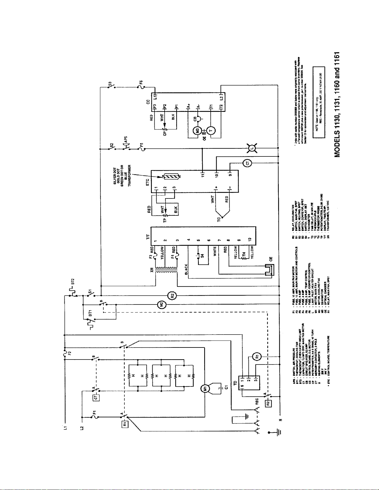
SCHEMATIC 1130 – 1131 S/N 2011383 & BELOW & 1160 – 1161 S/N 2011978 & BELOW
12
Impinger II –1100 Series Service Manual - Domestic
Page 13
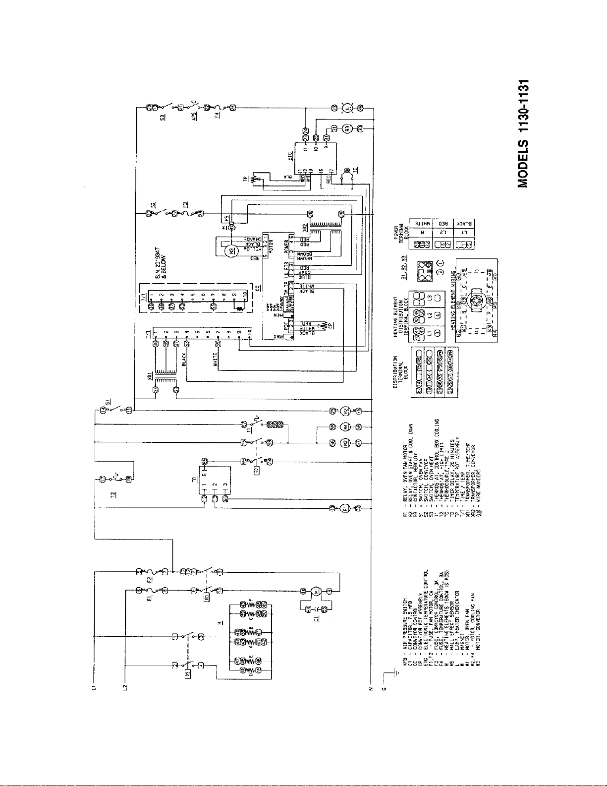
SCHEMATIC 1130 – 1131 S/N 2011384 & ABOVE
Impinger II –1100 Series Service Manual - Domestic
13
Page 14
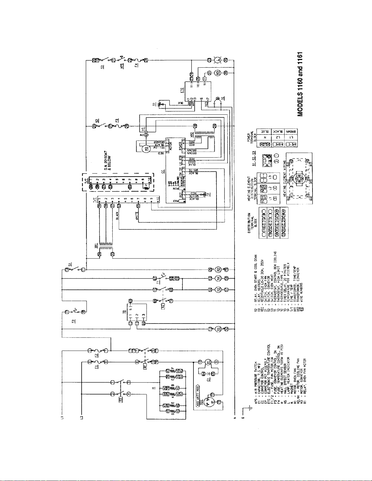
SCHEMATIC 1160 – 1161 S/N 2011978 & ABOVE
14
Impinger II –1100 Series Service Manual - Domestic
Page 15
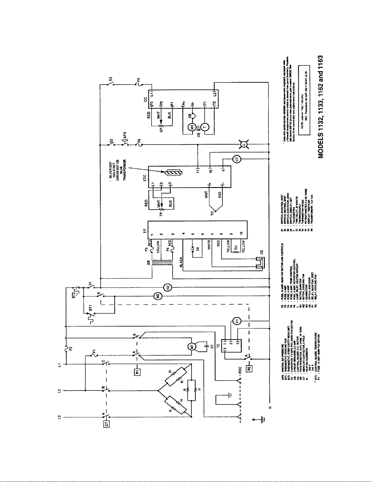
SCHEMATIC 1132 – 1133 S/N 2011383 & BELOW & 1162 – 1163 S/N 2011979 & BELOW
Impinger II –1100 Series Service Manual - Domestic
15
Page 16
SCHEMATIC 1132 – 1133 S/N 2011384 & ABOVE
16
Impinger II –1100 Series Service Manual - Domestic
Page 17
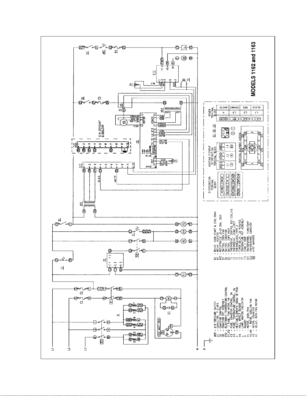
SCHEMATIC 1162 – 1163 S/N 2011978 & ABOVE
Impinger II –1100 Series Service Manual - Domestic
17
Page 18
TROUBLESHOOTING GUIDE 1116 - 1117
n
r
r
GAS OVENS
MODEL 1116 / NATURAL GAS / 120VAC / 60 HZ / 1 PHASE
MODEL 1117 / L.P. GAS / 120VAC / 60 HZ / 1 PHASE
REFER TO PROPER SCHEMATIC FOR IDENTIFIED COMPONENTS
SYMPTOM POSSIBLE CAUSE EVALUATION
Oven fan will not run Incoming Power Supply Check breakers/Reset if required Check power plug to
be sure it is firmly in receptacle. Measure incoming
power/call Power Co. if needed.
No main fan cool down
Main fan runs after 20
minute cool down
20 minute cool down
Time Delay Relay 120 VAC at terminal 2 should discontinue
No control box cooling Incoming Power Check main circuit breakers, reset if required, call powe
Main Fan Switch Check continuity between switch terminals.
20 Minute Time Delay With fan switch on, check for 120 VAC at terminal 2 of
Main Fan Relay Check continuity of 120 VAC coil. Check for power to
Cooling Fans 120 VAC should now be at the fan motors. If voltage is
Main Fan Switch Check continuity between switch terminal.
20 Minute Time Delay Check for 120 VAC at terminal #1 to neutral on 20
minute Time Delay Relay. If no voltage is present,
trace wiring back to power source. If voltage is present
at terminal #1, check for 120 VAC at terminal #2 to
neutral. If no voltage is present, and Main Fan Switch
is closed, replace Time Delay
Main Fan Relay Check for 120 VAC to coil of the Relay, if no voltage
is present, trace wiring back to 20 minute Time
Delay Relay. If voltage is present, check to insure
contacts are closing.Fuse, 10 Amp Check, replace if
necessary
Fuse Holder Check, replace if necessary.
Main Fan Motor Check for opens, shorts, or grounds. WITH POWER
: turn fan blade to check for locked rotor.
OFF
Capacitor Check for shorts or grounds. WARNING: Capacitor
has a stored charge, discharge before testing.
20 Minute Time Delay Relay
Main Fan Relay
Check for 120 VAC at pin #2 and #3 while main fan is
running. Turn off main fan switch and 120 VAC should
continue to be present for 20 minutes at terminal 2.
Check if relay is operating and terminals are remaining
closed for main fan cool down of 20 minutes
NOTE: The time delay relay will keep the coil of main fa
closed, maintaining main fan operation for cool down fo
approximately 20 minutes.
approximately 20 minutes after the main fan switch is
switched off. If the switch is open and voltage
continues at terminal 2, replace Time Delay. When
voltage at terminal 2 of Time Delay ceases ,the main
fan relay must open.
company if needed.
Time Delay.
the relay coil (120 VAC).
present, check motors for shorts or opens WITH
POWER OFF: Check for locked rotor.
18
Impinger II –1100 Series Service Manual - Domestic
Page 19

d
Cooling fans continue to
run after 20 minute cool
Cooling Fan Thermostat Thermostat should close at 120°F± 5°F and open at
100°F± 5°F.
Main Fan Relay Check to insure that contacts of main fan relay are
opening after 20 minute cool down
Oven will not heat Gas Supply Check for adequate gas supply and manual gas shut
off valve is open. Also, check flexible gas line
connection.
Main Fan If not operating, refer to "Oven fan will not run".
Heat Switch Check for continuity, replace if necessary
Fuse 10 amp Replace if necessary.
Fuseholder Replace if necessary
Centrifigual Switch of Main
Fan Motor
Check for 120 VAC at lead #47 (located at 6 pin
connector in raceway near the main fan motor) to
neutral. If no voltage is present, and motor is running,
replace motor.
(Oven Cavity) High Limit Terminals are normally closed, opens at Thermostat
660°F (350°C). If open, push in reset button and
retest. If thermostat will not hold for maximum oven
temperature, and oven is not exceeding temperature
dial setting, check for proper location of capillary bulb
in its spring holder. If above checks okay, replace hi-
limit thermostat.
Burner Blower Motor Visually check to see if motor is running. If not, check
for 120 VAC to motor at motor connector (wire #40
and #41). If voltage is not present, trace wiring back
to oven cavity High Limit. If voltage is present and
motor is not running, check for opens, shorts, or
grounds. Also, WITH POWER OFF: check for locked
rotor.
Control Box High Limit
thermostat
NOTE: Discontinued S/N
Terminals are normally closed, and open at 170°F ±
5°F (76.6°C ± 2.8°C). Check for proper operation. If it
will not reset and hold, replace thermostat.
2011383
Centrifigual Switch of Burner
Blower Motor
Check for 120 VAC at motor connector wire #42 to
neutral. If voltage is not present, trace wiring back to
control box High Limit . If voltage is present, check #43
to neutral. If voltage is not present and motor is
running, replace the Burner Blower Motor.
Burner Transformer Primary is 120 VAC with 24 VAC secondary. If 120
VAC is not present, trace wiring back to Burner Blower
Centrifugal Switch. If 120 VAC is present, check for 24
VAC at secondary of transformer. If no voltage is
present, replace transformer.
Ignition Control Note: The ignition control contains a safety lock-out
circuit. If a flame is not detected within 6 seconds after
the gas control valve is energized, the ignition control
will lock-out. To reset, turn the burner switch "off", wait
45 seconds and switch the burner system "on" to retry
ignition. 24 volts should be present at 24 volt terminals.
If not present, trace wiring back to burner transformer.
When 24 VAC is supplied, the control switches 120
VAC from L1 and L2 to the Hot Surface Ignitor. If 120
VAC is not present at L1 and L2, trace wiring back to
oven cavity High Limit Thermostat. If 24 VAC and 120
VAC are present and 120 VAC is not across the Hot
Surface Igniter terminals, replace the ignition control
Impinger II –1100 Series Service Manual - Domestic
19
Page 20

Hot Surface Igniter If 120 VAC is present at Hot Surface Igniter terminals,
visually check to see that the igniter is heating. (Igniter
may be viewed through the port glass in end of the
burner tube.) The Igniter should glow bright red. If the
igniter does not heat, replace the Igniter.
Ignition Control After 45 seconds of hot surface igniter pre-heat, the
ignition control will switch 24 VAC to the gas control
valves. Check for 24 VAC output from ignition control,
across terminals marked "valve" and "valve ground". If
no voltage is present, replace ignition control
Gas Control Valves When 24 VAC is supplied to the gas control valve, the
valves should open Check for gas pressure at the
manifold tap located just before the burner. If there is no
pressure, check the incoming gas supply to be sure all
manual valves are open and flexible gas hose is
properly connected. If gas is present at the oven and
coils of gas valve are energized, the gas valve is
defective. When 24 VAC is supplied to the gas control
valve the red burner indicator.
Flame will not stay lit Hot Surface Igniter/ Flame
Sensor
Six seconds after the gas valve opens, ignition must
occur. If flame is not detected, the ignition control will
shutoff and lock out. To reset the ignition control, turn off
the burner switch for 45 seconds then turn on the burner
switch to retry ignition. The ignition control requires a
minimum of 0.8 D.C. microamps To check flame
sensing operation, connect a digital multimeter (capable
of measuring D.C. micro-amps) between the "ground"
terminal on ignition control and the ground lead.
NOTE: This is a current measurement and the meter
must be connected in series. If these readings are not
achieved, check bypass orifice for obstructions. If
bypass orifice is clear, replace the hot surface
igniter/flame sensor.
NOTE: The D.C. micro amp test must be conducted
with the oven in low flame (bypass) operation. Turn the
temperature control to the lowest setting.
Power Supply If there is sufficient micro-amp current, but the flame will
not stay lit, check for proper polarity of the 120 VAC
power supply.
Ignition Control If there is sufficient micro-amp current, and the 120 VAC
polarity is correct, but the flame will not stay lit, replace
ignition control.
NOTE: check for proper ground connection on ignition
control.
Low flame is on, but no
main flame
NOTE: flame should be
present at this time
Check for 120 VAC at terminal #11 to neutral on
temperature control. If no voltage, trace voltage back to
Centrifugal Switch.
Tempe rature Control Turn the temperature adjustment knob to maximum
temperature position and check for 120 VAC at the load
terminal (#9) and neutral. If 120 VAC is present and unit
is not heating, refer to "Temperature Solenoid Valve" for
next check. If 120 VAC is not present, proceed.
20
Impinger II –1100 Series Service Manual - Domestic
Page 21

Thermocouple Probe WITH POWER ON AND THERMOCOUPLE LEADS
ATTACHED TO THE TEMPERATURE CONTROL
BOARD: Measure the D. C. millivolt output of these
leads. Refer to thermocouple chart on page 36 for
proper readings. If these readings are not achieved,
replace the thermocouple
Tempe rature Control
Potentiometer
WITH POWER OFF: remove the potentiometer leads
from the temperature control board and measure ohms
from black to white leads. The reading should be from
approximately 0 to 2.5 K ohms as the dial of the
potentiometer is turned throughout its full rotation.
From black to red leads, the reading should be
approximately 2.5 K ohms (constant) throughout the full
rotation of the dial. If these readings are not achieved,
replace potentiometer. If the thermocouple probe and
the control potentiometer check good, then the problem
is usually with the temperature control board.
Temperature Solenoid If 120 VAC is present on the Valve temperature control
board at load terminal (#9) to neutral, check for voltage
at temperature regulation valve. If voltage is present,
listen for valve to open and close. Also check for opens
or shorts in the coil. Replace as necessary.
Intermittent Heating Thermal/Overload of Main
Fan and Burner Blower
Motors
.
Conveyor will not run REFER TO PAGE 26
From S/N 2011383 and up REFER TO PAGE 29
Conveyor speed varying or intermittent REFER TO PAGE 26
From S/N 2011383 and up REFER TO PAGE 29
Time/Temp Display inoperative REFER TO PAGE 27
From S/N 2011383 and up REFER TO PAGE 29
Temp Display out or erratic REFER TO PAGE 27
From S/N 2011383 and up REFER TO PAGE 29
Impinger II –1100 Series Service Manual - Domestic
21
Page 22

TROUBLESHOOTING GUIDE 1100 THRU 1103
t
f
t
T
t
W
A
T
f
T
t
V
T
W
A
t
ELECTRIC OVENS
MODEL 1100 / 120/208 VAC / SINGLE PHASE / 60 HZ
MODEL 1101 / 120/240 VAC / SINGLE PHASE / 60 HZ
MODEL 1102 / 120/208 VAC / THREE PHASE / 60 HZ
MODEL 1103 / 120/240 VAC / THREE PHASE / 60 HZ
REFER TO PROPER SCHEMATIC FOR IDENTIFIED COMPONENTS
SYMPTON POSSIBLE CAUSE EVALUATION
Oven fan will not run Incoming Power Supply Check circuit breakers. Reset if required. Call Power Co.
needed.
Fuses, 10 Amp, Check, replace if necessary
Fuseholder Check, replace if necessary
Switch, Main Fan Check for continuity between switch terminals.
Main Fan Relay Check continuity of 120 VAC coil. Check for power to
relay coil (120 VAC). Check for 208/240 VAC to the relay
erminals
Main Fan Motor Check for opens, shorts, or grounds. WITH POWER
OFF: Turn fan blade to check for locked rotor
Capacitor Check for opens, shorts, or grounds.
No control box cooling Check for main fan operation. If not operating, refer to
"Oven fan will not run". Cooling Fan Motor 120 VAC
should be present at the fan motor. If voltage is present,
check for opens or shorts. .WITH POWER OFF: Check
or locked rotor of the fan motor.
No main fan cool down Cool Down Thermostat Check cool down thermostat (thermostat closes at 160°F
and opens at 140°F). Check for power (120 VAC) at cool
down thermostat. With cool down thermostat preheated,
check for continuity. If switch is open, replace.
Oven will not heat Main Fan Motor Check for main fan operation. If it is not operating, refer
o "Oven fan will not run".
High Limit Thermostat, Oven
Cavity
Switc h, Heat
Fuse, 3 Amp Check, replace if necessary.
Fuseholder Check, replace if necessary
ir Pressure Switch
emperature Control Check for 120 VAC supply at terminal #11 to neutral on
hermocouple Probe
erminals are normally closed. If open, reset the
hermostat and test for proper operation. If it will not
reset and hold, then replace.
ith switch on, check for 120 VAC on both terminals to
neutral. Replace if defective
his normally open switch should close when the main
an is activated. If adjustment is necessary (Refer to
Section D). Replace if defective.
emperature control. If no voltage is present, trace wiring
back to 3 amp fuse. Turn the temperature adjustment
knob to maximum temperature position and check for
120 VAC at the load terminal (#9) and neutral. If 120
AC is present and unit is not heating, refer to "Mercury
Contactor" for next check. If 120 VAC is not present,
proceed.
ITH POWER ON AND THERMOCOUPLE LEADS
TTACHED TO THE TEMPERATURE CONTROL
BOARD: measure D. C. millivolt output of these leads.
Refer to thermocouple chart on page 36 for proper
readings. If these readings are not achieved, replace
hermocouple.
22
Impinger II –1100 Series Service Manual - Domestic
Page 23

T
W
f
f
w
v
T
t
T
T
emperature Control
Potentiometer
ITH POWER OFF: remove the potentiometer leads
rom the temperature control board and measure ohms
rom black to white leads. The reading should be from
approximately 0 to 2.5k ohms as the dial of the
potentiometer is turned throughout its full rotation. From
black to red leads, the reading should be approximately
2.5k ohms (constant) throughout the full rotation of the
dial. If these readings are not achieved, replace
potentiometer. If the thermocouple probe and the control
potentiometer checks good, then the problem is usually
ith the temperature control board.
Mercury Contactor Check for 120 VAC to the contactor coil. If voltage is
present and contact will not activate, replace the
contactor. Also, check each contactor for proper high
oltage input and output
Heater Elements Check the Amp. draw on each leg for proper load.
Check the specification plate for rating information. If
the Amp. draw is low or high, check the individual
elements for opens, shorts, and proper resistance.
WITH POWER OFF: check resistance of the elements,
remove all leads from the elements and use an
accurate digital VOM. The element resistance should
be as follows: 208V - 27 ohms approximately, 240V -
36 ohms approximately.
Oven heats with switch
off
Mercury Contactor
he mercury contactor has probably malfunctioned in
he closed position. If there is no voltage to the
operating coil, but there is high voltage at the contactor
output, replace the mercury contactor.
Intermittent Heating
hermal/Overload of motor
he main fan motor is equipped with internal thermal
protection and will cease to operate if overheating
occurs. As the motor overheats and then cools, this will
cause the ovens to cycle on and off intermittently. This
may be caused by improper ventilation or preventative
maintenance. Also, most of the problems listed under
"Oven will not heat" can cause intermittent failure.
Conveyor will not run / REFER TO PAGE 26
Conveyor speed varying / REFER TO PAGE 26
or intermittent
Time/Temp Display / REFER TO PAGE 27
inoperative
Temp Display out or / REFER TO PAGE 27
inaccurate
Impinger II –1100 Series Service Manual - Domestic
23
Page 24

TROUBLESHOOTING GUIDE 1130 THRU 1133 / 1160 THRU 1163
ELECTRIC OVENS
MODEL 1130, 1160 / 120/208 VAC / SINGLE PHASE / 60 HZ
MODEL 1131, 1161 / 120/240 VAC / SINGLE PHASE / 60 HZ
MODEL 1132, 1162 / 120/208 VAC / THREE PHASE / 60 HZ
MODEL 1133, 1163 / 120/240 VAC / THREE PHASE / 60 HZ
REFER TO PROPER SCHEMATIC FOR INDENTIFIED COMPONENTS
SYMPTON POSSIBLE CAUSE EVALUATION
Oven fan will not run Incoming Power Supply Check circuit breakers. Reset if required. Call Power
Co. if needed.
NOTE: On Models 1160, 1161, 1162 and 1163,
disconnect any accessory from receptacle in the rear
of the oven and check for shorts or overloads.
Fuses, 10 Amp, Check, replace if necessary
Fuseholder Check, replace if necessary
High Limit Thermostat, Oven
Cavity
Switch, Main Fan Check for continuity between switch terminals.
Relay, Oven Start Check for continuity at relay coil, and visually check
20 Minute Time Delay Check for 120 VAC at terminal #1 to neutral on 20
Main Fan Relay Check for 120 VAC to coil of the Relay. If no voltage is
Main Fan Motor Check for opens, shorts, or grounds. WITH POWER
Capacitor Check for opens, shorts, or grounds
No main fan cool down 20 Minute Time Delay Check for 120 VAC at terminal #2 to neutral while
Oven Fan Relay Check if relay is operating and that the contacts
Main fan runs after 20
minute cool down
20 Minute Time Delay 120 VAC at terminal #2 should discontinue
Oven Fan Relay Check to insure that the contacts are opening after the
20 Minute Time Delay NOTE: ON/OFF operation of the fan switch will set the
Oven Start Relay Contacts should open when main fan switch is turned
Terminals are normally closed. If open, reset the
thermostat and test for proper operation. If it will not
reset and hold, replace thermostat.
for pull in of contacts.
minute Time Delay Relay. If no voltage is present,
trace wiring back to 10A fuse. If voltage is present
at terminal #1, check for 120 VAC at terminal #2 to
neutral. If no voltage is present, and oven start relay is
closed, replace Time Delay.
present, trace wiring back to 20 minute Time Delay
Relay. If voltage is present, check to insure contacts
are closing.
OFF: Turn fan blade to check for locked rotor.
oven is "on". Turn off the main fan switch, 120 VAC
should continue to be present for 20 minutes. If
voltage is not present for approx. 20 minutes, replace
the timer.
remain closed during the 20 minute cool down.
off.
approximately 20 minutes after main fan is switched
off. If the oven start relay contacts are open, and the
voltage continues at terminal #2 of the 20 minute
timer, for more than 20 minutes, replace the timer.
coil is de-energized
timer to 20 minutes. If the timer is accidentally reset,
turn off main breaker for 15 seconds to cancel
24
Impinger II –1100 Series Service Manual - Domestic
Page 25

No control box cooling Check for main fan operation. If not operating, refer to
"Oven Fan Will Not Run".
Oven Start Relay Check relay contacts. 120 VAC should be present.
Cooling Fan Motor(s) 120 VAC should be present at the fan motor. If voltage
is present, check for opens or shorts. WITH POWER
OFF: Check for locked rotor of the fan motor.
No automatic control Thermostat, Cooling Check the cooling fan thermostat. box cooling Fan
(Thermostat closes at 120°F and opens at 100°F.).
With the cooling fan thermostat pre-heated, check for
continuity. If switch is open, replace.
Cooling Fan Motor(s) 120 VAC should be present at the fan motor. If voltage
is present, check for opens or shorts. WITH POWER
OFF: check for locked rotor of the fan motor.
Control box cooling fan
continues to run
Thermostat, Cooling Fan This normally open thermostat should close at 120°F
(48.9°C) and reopen at 100°F (37.8°C).
Oven will not heat Main Fan Motor Check for main fan operation. If it is not operating,
refer to "Oven fan will not run".
Heat Switch With switch on, check for 120 VAC on both terminals
to neutral. Replace if defective.
Air Pressure Switch This normally open switch should close when the main
fan is activated. Adjust if necessary (Refer to page
23). Replace if defective.
Fuse, 3 Amp Check, replace if necessary
Fuseholder Check, replace if necessary
Temperature Control Check for 120 VAC supply at terminal #11 to neutral
on temperature control. If no voltage is present, trace
wiring back to 3-amp fuse. Turn the temperature
adjustment knob to maximum temperature position
and check for 120 VAC at the load terminal (#9) and
neutral. If 120 VAC is present and unit is not heating,
refer to "Mercury Contactor" for next check. If 120
VAC is not present, proceed.
Thermocouple Probe WITH POWER ON AND THERMOCOUPLE LEADS
ATTACHED TO THE TEMPERATURE CONTROL
BOARD: measure D. C. millivolt output of these leads.
Refer to thermocouple chart on page 36 for proper
readings. If these readings are not achieved, replace
thermocouple.
Tempe rature Control
Potentiometer
WITH POWER OFF: remove the potentiometer leads
from the temperature control board and measure
ohms from black to white leads. The reading should
be from approximately 0 to 2.5k ohms as the dial of
the potentiometer is turned throughout its full rotation.
From black to red leads, the reading should be
approximately 2.5k ohms (constant) throughout the full
rotation of the dial. If these readings are not achieved,
replace the potentiometer. If the thermocouple probe
and the control potentiometer check good, then the
problem is usually with the temperature control board.
Mercury Contactor Check for 120 VAC to the contactor coil. If voltage is
present and the contactor will not activate, replace the
contactor. Also, check each contactor for proper high
voltage input and output.
Heater Elements Check the Amp. draw on each hot leg for proper load.
Check the specifications plate for rating information. If
the Amp. draw is low or high, check the individual
elements for opens, shorts, and proper resistance.
WITH POWER OFF: To check resistance of the
elements, remove all leads from the elements and use
an accurate digital VOM. The element resistance
should be as follows: 208V - 27 ohms approximately
Impinger II –1100 Series Service Manual - Domestic
25
Page 26

240V - 36 ohms approximately.
Oven heats with switch
off
Mercury Contactor The mercury contactor has probably malfunctioned in
the closed position. If there is no voltage to the
operating coil, but there is high voltage at the
contactor output, replace the mercury contactor.
Intermittent Heating Thermal/Overload of Motor The main fan motor is equipped with internal thermal
protection and will cease to operate if overheating
occurs. As the motor overheats and then cools, this
will cause the units to cycle on and off intermittently.
This may be caused by improper ventilation or
preventative maintenance. Also, most of the problems
listed under "Oven will not heat" can cause intermittent
failure.
Conveyor Will Not Run Conveyor Switch Check for continuity between switch terminals
3 Amp Fuse Check, replace as needed
Fuseholder Check, replace as needed
S/N 2011383 and
above 1130 through
1133 – S/N 2011978
and above Models
1160 through 1163
Refer to Page 29
Speed Adjustment
Potentiometer
This is a 0 to 5 K ohm, 10 turn potentiometer. WITH
POWER OFF: Remove the red, black and white pot
leads from the motor control board at terminals P1, P2
and P3. With a digital multimeter, check the ohm
reading across the red lead (P3) to the black lead
(P1). This reading should be 5 K ohms ± 5% as the
pot is rotated from low to high. Place the meter leads
on the red lead (P3) and on the white lead (P2)
Rotating the pot. slowly, from low to high, the meter
reading should show an even transition from 0 to 5 K
ohms ± 5%. There should be no dead or open spots
through out the 10 turns of the pot. Check all three
leads to ground. There should be no continuity to
ground. If any of the above checks fail, replace the
pot.
DC Motor Control Board Check for 120 VAC input to the control board at
terminals L1 and L2. If not present, check the
conveyor switch and wiring back to 3 amp fuse and
then back to power source if necessary. If 120 VAC is
present at L1 and L2, check the VDC output at
terminals A+ and A-. If a DC voltage is not present,
check the 4 amp and the 1 amp fuses on thecontrol
board. If 120 VAC is present at terminals L1 and L2,
but DC Voltage is not present at A+ and A-, providing
the fuses are good, replace the board. If DC voltage
is present at A+ and A-, but motor does not run, check
gear motor as follows.
Conveyor Gear Motor If DC voltage is present at A+ and A-and the motor
does not run, first check the mini breaker and then the
conveyor. As described below under "conveyor."
WITH POWER OFF: Check the leads to the motor for
evidence of any shorts or opens, and each lead to
ground. Remove dust cover from the top of the motor
and rotate motor shaft to determine if there is a locked
rotor or a locked gear box (use care so encoder disc is
not damaged). If the motor fails the above tests,
replace motor.
Conveyor Check for any mechanical misalignment or improper
adjustment. Also check for worn bearings. The
Installation and Operations Manual shows proper
conveyor belt position. A conveyor belt that is too tight
will contribute to excessive load, bearing wear, and
wearing of slider bed rods.
Conveyor speed
varying or intermittent
Power Supply Check power supply at the DC control board for the
120 VAC at board terminals L1 and L2. If voltage is
not present and steady, check the main circuit
26
Impinger II –1100 Series Service Manual - Domestic
Page 27

breakers and call power company if necessary.
S/N 21011383 and
above Models 1130
through 1133 –
2011978 and above
Models 1160 through
1163 – Refer to page
29
Tach. generator and DC
Motor Control Board
WITH POWER OFF: Remove the leads from terminals
T1 and T2. Place the test leads of a digital test meter
on the tach. leads, turn power on, and the meter
reading should be approximately 20 to 25 VDC. This
reading is normally steady within ± 0.2 to 0.3 VDC. If
this reading is not within required VDC, place the test
meter probes on terminals A+ and A-. The meter
reading should be approximately 150 to 160 VDC and
steady within approximately 4 to 5 VDC. If the tach.
voltage is unsteady, and the board output is steady,
check the coupling for loose set screws or any type of
damage. If the coupling checks good, the tach. is
usually bad. If the board voltage output is unsteady
beyond limits, then the board is probably bad. Always
check the speed pot. Be sure it is okay before
changing a board or tach. This test is not always
100% accurate as this test is not performed at
operating speeds. However, this test is the best
method currently available. Readjustment should
always be attempted at least once before
replacement. See procedure for board adjustment on
page 41.
DC Gearmotor If the problem seems to be the motor or gearbox.
Check the brushes in the motor for excessive arching
and/or unusual wear. Check the motor and gearbox
from instruction located on page 26 under "possible
cause" listing "Conveyor gear motor".
Time/Temp Display
inoperative S/N
2011383 and above
Models 1130 through
1133 Refer to Page 29
12.6 VAC Power Supply Measure the transformer primary for a nominal 120
VAC input. Measure the secondary voltage output
which will be 12.5 to 15 VAC normally. Recheck
secondary output at rear of Time/Temp Display.
Terminals 1 to 3 should read 12.5 to 15 VAC.
Terminals 1 to 2 and 2 to 3 should be 1/2 of the
reading across 1 to 3. If you do not get the above
secondary readings, replace the transformer. If 120
VAC primary voltage is not available, refer to the
schematic and trace circuit for incoming power failure.
The older units have a 4 amp ambient fuse in each red
secondary lead. These may be jumpered to
determine if they are burnt out or intermittent.
Temp Display out or
inaccurate
NOTE: Time/Temp displays
use two types of temperature
sensors thermistor probe-2
yellow wires, thermocouple
Insert the thermocouple of your pyrometer into a finger
hole in the top center of the oven. Be sure the tip of
the thermocouple is not touching metal. The
pyrometer will indicate oven temperature.
probe-1 red wire and 1 white
wire
From S/N 2011383
and up Models 1130
through 1133 S/N
2011978 and up
Models1160
through1163 Refer to
Page 29
Thermistor Probe Disconnect the yellow tipped thermistor leads from the
time/temp. terminals 9 and 10. Measure the resistance
of the thermistor probe and temperature of oven. See
the chart on page 44 for proper resistance readings.
Inspect the thermistor bulb for its proper location in its
spring holder. Check for short in leads where they
enter the sensor bulb. Also check each thermistor lead
for short to ground.
Impinger II –1100 Series Service Manual - Domestic
27
Page 28

Thermocouple Probe Place your pyrometer thermocouple into the center of
top finger. Connect temperature meter to
thermocouple at terminals 9 & 10 on back of the
time/temp display. (Be sure to maintain proper
polarity on thermocouple connections.) Compare
actual oven temperature with the reading at the
time/temp display. If the temperature readings match,
re-calibrate or replace time/temp display. If the
readings do not match, replace thermocouple probe.
Erratic time/temp dispaly If strange or unusual behavior is experienced such as
a rolling of numbers, or lock up at a given number, first
check for a display circuit lock up. This can be caused
by a voltage spike or surge in the incoming power
lines. To eliminate this condition remove power from
the time/temp. display by shutting off the main fan
switch for 15 seconds, or if display stays on, (older
models) circuit breaker interruption may be required.
This should eliminate the problem. If the problem
continues, jumper the two fuses in the red wires
leading from the 12.6 VAC transformer to the display
on older units. If this does not solve the problem, it
may be coming in through the commercial power lines.
Suggest that customer contact his power company for
evaluation.
Temp Display inaccurate,
erratic or inoperative
Perform the power supply check, the thermistor probe
check, and then perform the time/temp simulator test.
Refer to Removal, Installation, and Adjustment section
for instructions (see page 42). Remember, when using
the time/temp simulator, remove all the leads from the
back of the display except the 3 power leads. After
completion of this test and if reinstalling display back
into the oven, the dip switches must be reset for oven
operation.
Time Display inaccurate,
erratic
Perform all checks as in the above evaluation. If the
time check is okay, or inoperative refer to the next
section, optical encoder.
Optical Encoder The above time/temp test should have already been
performed. Remove dust cover from the gear motor
and inspect the coupling and encoder disc. The
coupling set screws should be tight and not slipping on
the motor shaft or the tach. generator shaft. The
encoder disc should be firmly attached to the coupling
and not warped. Check the positioning of the optical
encoder disc. The disc should not be touching the
optical encoder assembly and the encoder assembly
should be mounted so it is squarely facing the
coupling shaft. This is to allow the infrared light
beams to be broken by the encoder disc. If all this is
okay, then replace the optical encoder assembly.
28
Impinger II –1100 Series Service Manual - Domestic
Page 29

STEPPER MOTOR DRIVE
Conveyor will not run Conveyor Switch Check for 120 VAC to conveyor switch. If no voltage is
present, trace wiring back to the oven power source.
WITH POWER OFF: Check continuity between switch
terminals.
Conveyor Fuse 3AMP Check, replace if necessary. (Not used on Model 1151)
Fuse holder Conveyor Control
(Stepper) Transformer
Check, replace if necessary. Check for 120 VAC supply
to primary of transformer, if voltage is not present, trace
wiring back to the fuseholder. If voltage is present,
check for output voltage from the transformer
secondary. NOTE: This control transformer outputs (2)
secondary voltages. Red Leads 29 VAC Brown Leads
10 VAC If BOTH secondary voltages are not present,
replace the transformer.
Speed Adjustment
Potentiometer
This is a 0 to 50k ohm, 10 turn potentiometer. WITH
POWER OFF: remove the 3 pin potentiometer cable
plug from the motor control board. With a digital
multimeter, check the ohm reading across the red lead
to the black lead, this reading should be 50k ohms ± 5%
as the potentiometer is rotated through its 10 turn
rotation. Place the meter leads on the red lead and
white lead. Rotating the potentiometer slowly, from low
to high, the meter should show an even transition from 0
to 50k ohms ± 5% through the 10 turn rotation of the
potentiometer. There should be no dead or open spots
through the 10 turns of the potentiometer. Check all
three leads to ground. There should be no continuity to
ground. If any of the above checks fail, replace the
potentiometer.
Conveyor Motor (Stepper)
Control
NOTE: if the conveyor drive motor becomes jammed,
the motor will stop turning. To reset, turn off conveyor
switch, wait 10 seconds and turn the conveyor switch
on. If the motor does not run, check for 2 to 29 VAC
across the motor terminals 1 to 2 and 3 to 5 on the
conveyor motor control. If voltage is not present at both
sets of terminals, replace control.
Conveyor Drive (Stepper)
Motor
Check the drive sprocket on motor output shaft to insure
that it is tight. WITH POWER OFF: Turn the motor shaft
to check for jammed gear box. Check motor windings.
Ohm readings on motor terminal -1-5, 2-6, 3-7, 4-8,
each reading should be approximately 2 ohms. If motor
shaft will not turn, replace conveyor drive (stepper)
motor.
Time/Temp Display
inoperative
12 VAC Power Supply
(Transformer)
Measure the transformer primary for a nominal 120 VAC
input, if voltage is not present, trace wiring back to the
oven power source. Measure the secondary output,
which will normally be 12-15 VAC. Voltage across
terminals 1 and 3 on the time/temp. display should read
12-15 VAC. Terminals 1-2 and 2-3 should be 1/2 the
voltage reading to 1-3. If the above secondary readings
are not achieved, replace transformer.
Time/Temp Display If proper voltage is present at terminals 1, 2, and 3 on
time/temp display, but the display is not lighted, recheck
all connections for tightness. If time/temp display is still
not operating, replace the time/temp display
Temp display out or
inaccurate
NOTE: Time/Temp displays
use two types of temperature
sensors thermistor probe-2
yellow wires thermocouple
Place the thermocouple of a pyrometer into the center of
the top finger. Be sure the tip of the thermocouple is not
touching metal. The pyrometer will indicate oven
temperature.
probe probe-1 red wire and 1
white wire
Thermistor Probe Disconnect the thermistor probe leads from the
Impinger II –1100 Series Service Manual - Domestic
29
Page 30

time/temp display terminals #9 and 10. Measure the
resistance of the thermistor probe. See chart on page
44 showing probe resistance at various oven
temperatures. If these readings are not achieved,
replace the thermistor probe.
Thermocouple Probe Place your pyrometer thermocouple into the center of
the top finger. Measure D.C. millivolts at terminals 9 and
10 on the time/temp display. See thermocouple chart on
page 36 for proper readings. Connect temperature
meter to thermocouple at terminals 9 & 10 on back of
the time/temp display. (Be sure to maintain proper
polarity on thermocouple connections.) Compare actual
oven temperature with the reading at the time/temp
display. If the temperature readings match, recalibrate or
replace time/temp display. If the readings do not match,
replace thermocouple probe.
Power Supply If a strange or unusual behavior is experienced, such as
a rolling of numbers, or lock-up at a given number, first
check for a display circuit lock-up. This may be caused
by a voltage spike or surge in the incoming power lines.
To eliminate this condition, remove power from the
time/temp display by shutting off the main fan switch for
15 seconds. This should eliminate the problem. If this
does not solve the problem, it may becoming in through
the Commercial power lines. Suggest that customer
contact their power company for evaluation.
Temp display
inaccurate erratic, or
inoperative
Time Display inaccurate
erratic, or inoperative
Conveyor Drive (Stepper)
Magnet Check to insure that the magnet (cemented to shaft of
Hall Effect Sensor Check for any physical damage to Hall Effect sensor
Conveyor Drive (Stepper
Time/Temp Display Perform the power supply check, the thermistor probe
check, and then perform the time/temp simulator test.
Refer to page 45 for instructions. Remember, when
using the time/temp simulator, remove all leads from the
back of the time/temp display except the 3 power leads.
After completion of the test, and if re-installing time/temp
display back in the oven, the dip switches must be reset
for oven operation, and the time/temp display must be
re-calibrated. If readings are not achieved, replace
display
Perform all checks as in the above evaluation. If the time
check is okay, refer to the next section.
Check to see if the conveyor drive (stepper) motor is
Motor
Control)
running. If motor is not running, refer to "Conveyor will
not run" on page 29.
conveyor drive [stepper] motor) has not been damaged,
(mounted on conveyor drive [stepper] motor). Check all
wiring and connections for damage. If the motor is
running, the magnet is in place, but the display shows"--
:--" the Hall Effect Sensor may be defective or
improperly connected.
Check all connections for tightness or proper location
and check all wiring for visible damage. Replace as
needed. If there is still no time display and all the above
have checked out, replace the stepper control.
30
Impinger II –1100 Series Service Manual - Domestic
Page 31

REMOVAL, INSTALLATION, AND ADJUSTMENT
IMPINGER II CONVEYOR OVEN
MOTOR, MAIN FAN
1. Shut off power at main breaker.
2. Disconnect motor wiring of main fan motor, note wire colors for reassembly, and remove entire oven back from
the oven. Refer to "main fan" (See Below) for removal information.
3. Remove the main fan.
4. Remove 4 screws from the motor support assembly.
5. Remove the motor mounting clamp and pull the motor away from the oven back assembly.
6. Remove motor mounting fixture.
7. Install the motor in reverse order insuring that the motor shaft is centered in the
8. Shaft tube of the oven back.
CAPACITOR, MOTOR
Model 1100-1106
Capacitor is located under motor cover in rear of unit and held in place by a plastic wire
tie.
1 Discharge capacitor, remove and replace.
FOR ALL OTHER 1100 MODELS
Capacitor is located under rear control box cover and held in place by a plastic wire tie.
MAIN FAN
1. Shut off power at main breaker.
2. Remove motor cover from back of oven.
3. Disconnect and mark motor wiring of main fan motor and remove entire oven back from oven.
NOTE: Turning the oven back bolts back and forward while applying a spray lubricant or penetrating oil will help
minimize breakage.
4. Loosen and remove set screw in hub of fan.
5. Remove fan. The motor shaft has a flat making removal of fan fairly easy. If trouble is encountered, apply a
spray lubricant or penetrating oil in set screw hole and on motor shaft.
NOTE: This fan is balanced by the manufacturer and must be handled carefully.
Suggested storage is by suspending the fan through the shaft hole.
6. Reinstall fan with the tips of the fan blade closest to the oven back.
7. Position of the fan on the motor shaft will be 1 1/2" (3.81cm) from the top of the oven back cone to the bottom of
the fan hub. Refer to drawing. The oven back must be removed to make this measurement.
8. Align set screw with motor shaft flat and tighten.
9. Reassemble in reverse order.
FAN SPIDER
NOTE: MEASUREMENT MUST BE
MADE FROM CONE TO FAN SPIDER
FAN HUB
CONE
Impinger II –1100 Series Service Manual - Domestic
1 1/2 INCH
31
Page 32

RELAY, DPST
1. Shut off power at main breaker.
2. Remove conveyor.
3. Remove control compartment covers.
4. Remove leads from relay and mark for reassembly.
5. Remove mounting screws and lift out relay.
6. Reassemble in reverse order.
TIME DELAY, 20 MINUTE
1. Shut off power at main breaker.
2. Remove conveyor.
3. Remove front control compartment cover.
4. Unplug all wires and mark for replacement.
5. Remove center mounting screw.
6. Reassemble in reverse order.
NOTE: Do not over tighten the mounting screw as this may damage the internal potted
electronic components.
COOLING FAN
1. Shut off power at main breaker.
2. Remove conveyor.
3. Remove front control compartment cover.
4. Remove 4 screws from fan frame.
5. Remove fan and unplug female cord receptacle.
6. Reassemble in reverse order.
NOTE: All current models have 2 of these cooling fans.
7. The second cooling fan is located in the rear of the rear control compartment. On older models of the
1116,1117,1152 through 1158 the fan was attached to a metal box on rear of oven. Metal box was removed
first. Newer ovens have fan mounted on inside of oven back and are removed from inside.
THERMOSTAT, COOL DOWN
Model 1100-1106 only
1. Shut off power at main breaker.
2. Remove conveyor.
3. Remove control compartment covers.
4. Remove 2 screws from holding bracket located in upper rear of the control compartment.
5. Remove the 2 leads and remove thermostat.
6. Reassemble in reverse order.
RELAY, DPST
1. Shut off power at main breaker.
2. Remove conveyor.
3. Remove front control compartment cover.
4. Remove leads and mark for reassembly.
5. Loosen mounting screws and remove.
6. Reassemble in reverse order.
THERMOSHETAT, COOLING FAN
1. Shut off power at main breaker.
2. Remove conveyor.
3. Remove front control compartment cover.
4. Remove lead wires and mark for reassembly.
5. Remove 2 screws and remove thermostat.
6. Reassemble in reverse order.
32
Impinger II –1100 Series Service Manual - Domestic
Page 33

MOTOR, BURNER BLOWER
This unit comes equipped to be used for other models of ovens. For use on the
Impinger II Series, the mating plug with the loose wires may be discarded.
TO REMOVE BLOWER MOTOR:
1. Shut off power at main breaker.
2. Remove conveyor.
3. Remove control compartment covers.
4. Disconnect the plug on blower motor. Plastic locks on side of plug need to be depressed.
5. Remove three screws holding blower horn to burner.
6. Remove air shutter from old unit and install on new unit. If air shutter of old unit is damaged or lost,
replace with new air shutter 369401.
7. Reassemble in reverse order.
8. Adjust air shutter opening if necessary. Set air shutter at 50% open and adjust to get a blue flame with an
occasional tip of yellow under high flame. A glass view port in the burner assembly should be used to
observe flame.
CLEANING OF THE BLOWER FAN IS NECESSARY ON A PREVENTIVE MAINTENANCE SCHEDULE.
See Blower Wheel, Burner below
BLOWER WHEEL, BURNER
This is part of the burner blower motor assembly
TO REMOVE THE BLOWER WHEEL FOR PERIODIC CLEANING:
1. Disconnect power and remove control compartment covers.
2. Remove air shutter held by 3 screws.
3. Loosen set screw on blower wheel hub and pull straight out.
4. Reassemble in reverse order.
NOTE: There is no critical placement of the blower wheel on the motor shaft. Just
back as far as it will go and then spin the blower to be sure it is not rubbing.
AIR PRESSURE SWITCH
1. Shut off power at main breaker.
2. Remove conveyor.
3. Remove front control compartment cover.
4. Remove air switch cover plate.
5. Disconnect wiring and mark for reassembly.
6. Loosen 2 screws and remove air switch.
7. Disconnect 1/4" air tube.
8. Reassemble in reverse order.
9. Turn on power and calibrate air switch as follows:
a) Turn adjusting screw counter clockwise to full out position.
b) Turn main fan and heat switch on.
c) Turn adjusting screw clockwise until heat shuts off.
d) Turn adjusting screw (counterclockwise) 1/4 turn and unit should heat.
NOTE: Test as follows
e) Oven must be tested in heated condition.
f) Remove main fan fuse. Main fan should shut down, deactivating air switch causing
heat to shut off in approximately 5 to 25 seconds.
g) Fine tune adjustment as needed.
Impinger II –1100 Series Service Manual - Domestic
33
Page 34

TEMPERATURE CONTROL BOARD
NOTE: If your unit contains a Fenwal temperature control board, (see below) replace it with a thermologic
control board.
TEMPERATURE CONTROL BOARD CONVERSION - FENWAL TO THERMOLOGIC
(FOUND ONLY IN ELECTRIC UNITS BELOW S/N 2000861)
1. Remove Fenwal board.
2. Remove 5K ohm potentiometer
3. Remove wire #63 from oven. This wire is connected to Fenwall board at terminal #5.
4. Install new thermologic board with 2 screws.
5. Install new 2.5K ohm potentiometer.
6. Attach leads to thermologic board as shown in drawings. See pages 34 & 35.
Located in control compartment below drive end of the conveyor
1. Shut off power at main breaker and remove conveyor.
2. Remove front control compartment cover.
3. Remove the two mounting screws.
4. Remove the electrical leads and replace the control board.
5. Identify the style of thermologic board by looking at the top of the transformer
on the board. There are five styles of boards, each identified by a color marked
on the transformer, either RED, BLUE, GREEN, GOLD, OR A SILVER DOT. Refer to Pages 34 & 35
showing proper wiring connection.
6. NOTE: When mounting a new temperature control board, DO
NOT over tighten the two mounting screws.
7. Turn the potentiometer fully counterclockwise.
8. Loosen the Dial/Knob set screw and position the 50°F mark at the pointer.
NOTE: The thermocouple of your test meter should be inserted through a finger hole
in the top center of the oven, and the oven pre-heated for 30 minutes to stabilize
the oven at set temperature. The thermocouple probe must not touch metal, it must
sense air temperature only.
9. Adjustment of the GREEN, GOLD OR SILVER dot control board may be required when installing a new
board. Adjustment is seldom required on RED and BLUE boards.
10. For RED or BLUE control boards with the temperature control dial at maximum,
the reading on your temperature test meter should be between 555°F (290°C)
and 575°F (302°C). If not at this temperature adjust pot P3 to achieve these
figures. Refer to page 35.
11. For the GREEN, GOLD OR SILVER dot control board, place the test probe of your meter in position as
indicated in prior note. Set the oven temperature control dial 500°F(260°C), adjust pot P6 (see page 34) to
achieve a temperature reading on test meter of 500°F(260°C). CCW to increase, CW to decrease.
12. Adjust Time/Temp Display Pot. "Temp Cal" for 500°F(260°C).
RED
POTENTIOMETER
2.5 K OHMS
TRANSFORMER MARKED
WITH GREEN,GOLD OR
SILVER DOT
34
BLACK
THERMOCOUPLE
TYPE J
WHITE
1
2
3
+
6
7
-
P 3
P 5P 6
L 1 120 VAC
11
L 2
10
9
LOAD
Impinger II –1100 Series Service Manual - Domestic
Page 35

BLACK
THERMOCOUPLE
TYPE J
RED
RED
WHITE
POTENTIOMETER
2.5 K OHMS
POTENTIOMETER
2.5 K OHM
1
2
3
+
6
7
-
P 3
TRANSFORMER
MARKED IN BLUE
L 1 120 VAC
11
L 2
10
9
LOAD
TRANSFORMER
MARKED IN RED
13
12
10
L 1 120 VAC
L 2
LOAD
THERMOCOUPLE
TYPE J
WHITE
BLACK
1
3
4
5
+
6
7
-
THIS BOARD DISCONTINUED
AT S/N 2000932
P 3
TEMPERATURE CONTROL POTENTIOMETER, 0-2.5K OHMS, 1 TURN
1. Shut off power at main breaker.
2. Remove front control box cover.
3. Loosen and remove temperature control knob.
4. Remove hex nut and washer then remove pot from rear of compartment.
5. Remove and mark wiring for replacement.
6. Replace in reverse order.
7. Recalibrate the dial. (See "Temperature Control")
THERMOCOUPLE PROBE
The sensor bulb is located in the oven compartment behind the lower finger, and held
in position by a wire form holder.
CAUTION: ALLOW OVEN TO COOL
1. Shut off power.
2. Remove conveyor and lower finger.
3. Remove control compartment covers.
4. Remove sensor bulb from the wire form holder, pull thermocouple out of the oven through the access tube
and disconnect leads from terminals 6 and 7 of the temperature control board.
5. To install, push thermocouple bulb through the access tube and place in wire form
holder. Be sure that wire form holder is exerting enough pressure on the sensor
bulb to hold it in place. If sensor bulb is not held securely, replace the wire form holder or bend the holder
slightly to hold sensor bulb in place.
6. Reconnect RED lead to terminal 7(-) and WHITE lead to terminal 6(+).
7. Replace conveyor and fingers.
Impinger II –1100 Series Service Manual - Domestic
35
Page 36

THERMOCOUPLE MEASUREMENT CHART:
EXPLANATION: The junction temperature is the ambient air temperature where the
thermocouple fastens to the electronic temperature control board.
200°F 250°F 300°F 325°F 350°F 400°F 425°F 450°F 500°F 550°F 600°F
90°F 3.26 4.77 6.30 7.06 7.83 9.37 10.14 10.91 12.46 14.00 15.53
J
88°F 3.32 4.83 6.36 7.12 7.89 9.43 10.20 10.97 12.51 14.05 15.59
U
86°F 3.37 4.88 6.41 7.17 7.94 9.49 10.26 11.03 12.57 14.11 15.65
N
84°F 3.43 4.94 6.47 7.23 8.00 9.54 10.31 11.09 12.63 14.19 15.71
C
82°F 3.49 5.00 6.53 7.29 8.06 9.60 10.37 11.14 12.69 14.23 15.76
T
80°F 3.55 5.06 6.59 7.35 8.12 9.66 10.43 11.20 12.74 14.28 15.82
I
78°F 3.60 5.11 6.64 7.40 8.17 9.72 10.49 11.26 12.80 14.34 15.86
O
76°F 3.66 5.17 6.70 7.46 8.23 9.77 10.55 11.32 12.86 14.40 15.94
N
75°F 3.69 5.20 6.73 7.49 5.26 9.80 10.57 11.35 12.89 14.43 15.97
74°F 3.72 5.23 6.76 7.52 8.29 9.83 10.60 11.37 12.92 14.46 15.99
72°F 3.78 5.29 6.82 7.58 8.35 9.89 10.66 11.43 12.97 14.51 16.05
70°F 3.83 5.34 6.87 7.63 8.40 9.95 10.72 11.49 13.03 14.57 16.11
T
68°F 3.89 5.40 6.93 7.69 8.46 10.00 10.78 11.55 13.09 14.63 16.17
E
66°F 3.95 5.46 6.99 7.75 8.52 10.06 10.83 11.61 13.15 14.69 16.23
M
64°F 4.01 5.52 7.05 7.81 8.58 10.12 10.89 11.66 13.20 14.74 16.28
P
62°F 4.06 5.57 7.10 7.86 8.63 10.18 10.95 11.72 13.26 14.80 16.34
60°F 4.12 5.63 7.16 7.92 8.69 10.24 11.01 11.78 13.32 14.86 16.40
O V E N T E M P
MERCURY CONTACTOR
1. Shut off power at the main breaker.
2. Remove conveyor.
3. Remove control compartment covers.
4. Disconnect contactor wires and mark for reinstallation.
5. Remove screws from mounting bracket and replace contactor.
NOTE: Be sure contactor is not mounted upside down at this will cause a constant on
6. Reassemble in reverse order.
GAS VALVE
1. Shut off power at main breaker.
2. Shut off the gas supply in the main line to the oven.
3. Disconnect the flexible gas hose.
4. Remove the control compartment covers.
5. Remove the manual gas shut off valve from piping.
6. Remove screws from the bulkhead plate located on rear of oven at the gas pipe.
7. Remove the section of gas pipe to gas valve.
8. Disconnect the electrical leads from the solenoid valve.
9. Loosen the gas line union located near the burner and remove the gas valve and
solenoid valve assembly.
10. Finish removal of the gas piping from gas valve.
11. Replace in reverse order.
12. Check all gas fittings for leaks.
13. Adjust the gas manifold pressure on the gas valve. "Refer to the specification plate
on the oven for proper rating".
SOLENOID VALVE
1. Shut off power at main breaker.
2. Shut off gas supply.
3. Remove rear control box cover.
4. Disconnect wires from solenoid valve. Mark wires for reassembly.
5. Loosen pipe union in piping assembly.
6. Remove 4 nuts from burner manifold and remove valve assembly.
condition.
36
Impinger II –1100 Series Service Manual - Domestic
Page 37

7. Remove piping from solenoid valve.
8. Reassemble in reverse order.
NOTE: Some piping changes may be required. See instructions supplied with replacement part.
HEATING ELEMENTS
1. Shut off power at main breaker.
2. Remove back cover.
3. Disconnect heater element wire and mark for reassembly
.
4. Disconnect motor wiring and mark for reassembly.
5. Remove oven back from oven.
6. Remove fan shroud.
7. Heater element may now be unbolted and removed.
8. Check heater elements to be sure they are the proper replacement.
9. Reassemble in reverse order.
NOTE: Be sure the lead terminals are tight.
IGNITION CONTROL
1. Shut off power at main breaker.
2. Shut of the gas supply in the main line to the oven.
3. Remove conveyor.
4. Remove the front control compartment cover.
Note: After S/N 2011383 a removable drip tray is located above the ignition control.
5. Disconnect the wires from the ignition control and mark their location for reinstallation.
6. Remove the 4 mounting screws and remove the control.
7. Reassemble in reverse order.
8. Turn on electrical power and gas supply, then check the system for proper operation.
26
27
YELLOW
YELLOW
33
VALVE
VALVE
GND
25 V
25 V
GND
BURNER
GROUND
IGNITION CONTROL
TRANSFORMER, STEP DOWN 24 VAC
1. Shut off power at the main breaker.
2. Remove conveyor.
3. Remove front control compartment cover.
4. Remove wires from transformer and mark for reassembly.
5. Remove 2 mounting screws and replace transformer.
6. Reassemble in reverse order.
BURNER VENTURI
See "Hot Surface Igniter"
L 2
NEUTRAL
HSI
120 V
HSI
120 V
L 1
HOT
11
34
35
32
Impinger II –1100 Series Service Manual - Domestic
37
Page 38

HOT SURFACE IGNITER
1. Shut off the electrical power at main breaker.
2. Shut off the gas supply in the main line to the oven.
3. Remove conveyor.
4. Remove rear control compartment cover.
5. Remove Conveyor Motor.
6. Remove electrical plug from the burner cap.
7. Loosen the pipe union in the gas line.
8. Remove 3 screws holding burner cap to burner tube.
9. Pull out on burner cap removing cap and burner venturi.
10. The hot surface igniter is held in place on the burner venturi by a screw, loosen
screw and remove igniter.
11. Replace in reverse order.
NOTE: Care must be used when handling the hot surface igniter as they are quite fragile and may be easily
broken if dropped or bumped.
ORIFICE, MAIN BURNER
1. Shut off power at main breaker.
2. Shut off gas at main line to the oven.
3. Remove conveyor.
4. Remove control compartment covers.
5. Loosen 4 nuts holding manifold to burner cap.
6. Loosen pipe union. Remove valve and manifold.
7. Remove main orifice
8. Reassemble in reverse order.
ORIFICE, BYPASS
1. Loosen flare nut and remove bypass orifice.
2. Reassemble in reverse order.
THERMOSTAT, HIGH LIMIT, OVEN CAVITY
1. Shut off power at main breaker.
2. Remove conveyor.
3. Remove control compartment covers.
4. Remove screws from bracket.
5. Remove the mounting nut from the threaded shaft.
6. Remove the capillary tube bulb from the wire holder in the oven heating chamber.
NOTE: Access to the capillary tube bulb is through the front door, after removing the conveyor and fingers.
7. Insert the new capillary tube bulb through the tube into the oven cavity and into the wire form holder
NOTE: The wire form must hold the bulb firmly. If it does not, compress the wire form slightly to increase the
pressure.
8. Reassemble in reverse order.
9. Push the reset button. Test system for proper operation.
THERMOSTAT, HIGH LIMIT
1. Shut off power at main breaker.
2. Remove conveyor.
3. Remove control compartment covers.
4. Remove 2 screws from holding bracket located in upper rear of the control compartment.
5. Remove the 2 leads and remove thermostat.
NOTE: Push reset button
6. Insure that aluminum probe and teflon washer are in place (if applicable), then reassemble in reverse order.
7. Insure that thermostat is in firm contact with the aluminum probe (if applicable).
38
Impinger II –1100 Series Service Manual - Domestic
Page 39

LAMP, PILOT BURNER
LENS, PILOT LAMP
1. Shut off power at main breaker.
2. Remove conveyor.
3. Remove front control compartment cover.
4. Remove terminals from pilot lamp.
5. Grasp body of the light assembly and slide to the side disengaging body from light lens.
6. Remove lens by pushing out from rear.
7. Reassemble in reverse order.
COUPLING, CONVEYOR DRIVE
FOR ALL 1100 MODELS
This coupling has a plastic or rubber sleeve connecting two metal drive ends.
The metal drive end on the conveyor side is secured by a ball plunger screw,
This is not a set screw and should never
be over tightened.
PROCEDURE FOR ADJUSTING DRIVE COUPLING:
1. Place one metal end on conveyor shaft.
2. Install ball plunger and adjust so the spring loaded ball will drop into the dimple on the flat of the conveyor
drive shaft. To test, apply pressure on metal end towards the conveyor. The ball detent should pop up out of
the dimple and coupling end will slide back to conveyor frame.
3. Place other drive end on motor shaft,
4. Push conveyor frame to front side of oven conveyor opening.
5. Adjust the metal drive end on conveyor shaft so ball detent is in the dimple.
6. Lift the conveyor drive side slightly and place sleeve on conveyor side metal drive end.
7. Adjust motor side coupling drive end so sleeve is now held in place between the drive ends and tighten set
screw on motor side firmly.
To remove conveyor, simply grasp the coupling sleeve and pull towards conveyor.
The sleeve and drive end will slide towards the conveyor and separate from the motor
drive.
GEARMOTOR, D.C., CONVEYOR
1. Shut off power at main breaker.
2. Remove conveyor.
3. Remove control compartment covers.
4. Remove metal drive end from the motor shaft.
5. Remove electrical leads from gearmotor assembly and mark for proper reassembly.
6. Remove 4 screws holding gearmotor to the side wall of control compartment.
7. To remove tach., optical encoder assembly, and coupling and encoder disc refer to the
following instructions.
8. Reassemble in reverse order using care to readjust motor properly to be in line
with conveyor coupling.
NOTE: If a new gearmotor is installed, the D.C. motor control board must be recalibrated.
COUPLING AND ENCODER DISC
1. Remove gearmotor assembly (See "GEARMOTOR" )
2. Remove dust cover above motor.
3. Loosen both allen set screws (.050 inch allen wrench) located on coupling hub.
4. Remove 3 screws from tach. bracket, loosen the 4th.
5. Remove encoder assembly, see "OPTICAL ENCODER ASSEMBLY" in following procedure.
6. Push coupling down on motor shaft. Swivel tach. bracket aside and remove coupling.
7. To install, push coupling on to motor shaft. The encoder disc must be nearest motor.
8. Refasten tach. bracket in proper alignment.
9. Tighten the set screw on the tach. side first maintaining the .010 minimum dimension between the coupling
hub and tach.
10. Pull the coupling apart (approximately 1/8",3.2mm) and fasten the motor side set screw.
Impinger II –1100 Series Service Manual - Domestic
39
Page 40

11. Install the optical encoder, refer to "OPTICAL ENCODER" in this section for adjustment.
NOTE: The thin, slotted encoder disc must be handled with care so not to bend it.
12. Recheck tightness on the set screws to be sure they are tight. If available,
LOC TITE (the removable kind) should be used to secure set screws.
OPTICAL ENCODER ASSEMBLY
1. Remove gearmotor assembly (see "GEARMOTOR") Above.
2. If replacing with new assembly, cut wires to remove as new wires and plug are provided. If only
removing for access to coupling, see step 3.
3. Remove pins from connector with pin extractor tool, P/N 369600.
4. Loosen dust cover screws and pull dust cover away from motor.
5. Remove 2 screws from optical encoder and remove encoder.
6. Reassemble in reverse order.
7. To adjust optical encoder:
a. Position the encoder assembly so it does not rub the coupler hub and is
square with the encoder disc. The infrared light beam will be broken
by slots in the encoder disc. The encoder disc should not touch the bottom
or top of the optical encoder, if it does, readjust the coupling. The digital
speed readout may be observed to check proper adjustment of the optical
TACH. GENERATOR
1. Turn off power at main breaker.
2. Remove gearmotor assembly (see "GEARMOTOR")
3. Remove tach. cover plate and tach. leads. Mark wires for reassembly.
4. Remove 2 slotted screws from dust cover base and remove dust cover.
5. Loosen coupling set screw (.050 inch allen wrench).
6. Remove tach. bracket from motor. (4 screws)
7. Remove 4 screws from base of tach. and tach. is now free for removal.
8. Reassemble in reverse order. Maintain spacing of .010 minimum between tach.bracket and coupler hub.
NOTE: If a new tach. generator is installed, the D.C. motor control board MUST
BERECALIBRATED
. There is no repair procedure for the tach. If defective, replace.
D. C. MOTOR CONTROL BOARD
L 1 A+
4 A. FUSE 1 A. FUSE
.
RESISTOR
L 1 A+
4 A. FUSE 1 A. FUSE
RESISTOR
L 1 L 2 A +A -
L 2
A -
P 2
P 3
P 1
MAX MIN IR CL TACH
BOARD P/N 369155
STYLE 1
T 1 T 2
MAX MIN
BOARD P/N 369155
L 2
A -
P 2
P 3
P 1
T 1 T 2
STYLE 2
MIN MAX
S 1
S 2
BOARD P/N 369155
STYLE 3
Three different styles of control boards have been used and all three are still usable.
All three were supplied under the same part number.
TO REPLACE THE CONTROL BOARD:
1. Turn off power at main breaker and remove front control compartment cover.
2. Remove conveyor.
3. Remove and mark all wires from board
4. Remove control board bracket and board from unit, 3 screws.
5. Remove control board from mounting bracket. Remove 4 screws, lockwashers, and nuts.
40
Impinger II –1100 Series Service Manual - Domestic
RESISTOR
CAPACITOR
T 2T 1S 3
Page 41

6. Install new control board and bracket.
7. Attach wires to their proper terminals, refer to the drawings for proper terminal identification.
8. Perform calibration on the control board as specified using the calibration procedure for your style of board.
NOTE: When a control board, motor, tach. generator, or speed adjustment potentiometer is replaced, the
control board must be calibrated. When calibration of control board is complete, seal the adjustment pots.
(See "Control Board Adjustment")
STYLE 1 CONTROL BOARD ADJUSTMENT
NOTE: A digital meter must be used for this adjustment.
1. Voltage at L1 and L2 terminals of the control board is to be 120 VAC ± 10%.
2. Connect a digital
volt meter to terminals A+ and A-, set meter on 200 VDC scale.
3. Turn speed control pot. (on oven control panel) to its maximum speed setting.
4. Turn "MAX", "MIN", and "IR" pots counter clockwise until they stop. (DO NOT
turn CL pot.)
5. Adjust "TACH" pot. so the volt meter indicates 130 VDC ± 0.5 volts.
6. Adjust "IR" pot. to read between 1.5 and 2 VDC above tach. reading.(Example: If tach. reading would be
130.3 then adjust IR to between 131.8 VDC and 132.3 VDC.)
7. Turn speed control pot. to its minimum speed setting.
8. Adjust "MIN" pot. so the voltmeter indicates between 6 and 10 VDC.
9. Turn speed control dial to obtain a reading of 22 VDC on your meter. Observe for approx. 30 seconds to see
if stable within ± 0.5 VDC. Repeat at 35 VDC.
10. Check speed of conveyor and adjust time/temp. display if necessary.
11. Seal pots with Glyptol or nail polish.
STYLE 2 AND STYLE 3 CONTROL BOARD ADJUSTMENT
NOTE: A digital meter must be used.
1. Voltage at L1 and L2 terminals of the control board is to be 120 VAC ± 10%.
2. Connect a Digital
voltmeter to terminal T1 and T2, set the meter on DC scale.
3. Turn the speed control pot. (on oven control panel) to its maximum speed setting.
4. Adjust the "MAX" pot. so the voltmeter indicates 15.8 to 15.9 VDC.
5. Turn the speed control pot. to its minimum speed setting.
6. Adjust the "MIN" pot. so the volt meter indicates 0.7 to 0.9 VDC.
7. Reset the speed control pot. to its maximum speed setting and check if voltage is still at 15.8 to 15.9 VDC.
Readjust if necessary.
8. Reset the speed control pot. to its minimum speed setting and check if voltage is still at 0.7 to 0.9 VDC.
Readjust if necessary.
9. If readjustment of either the "MAX" or "MIN" pot. was necessary, the opposite must always be checked until
both "MIN" and "MAX" are in proper adjustment.
10. Measure the speed of the conveyor and adjust the time/temp. display if necessary.
11. Seal pots with Glyptol or nail polish.
NOTE: Occasionally a new board (Style 2 and 3 only) is so far out of adjustment that you will be unable to
adjust to the correct voltage. To correct, turn both the "MAX" and MIN" pots 10 turns in either direction and
then 5 turns in opposite direction. This will center the pots and allow them to be calibrated. If after this
procedure, the board will not adjust, it is probably defective.
REVERSAL OF CONVEYOR BELT - D.C. Motor
All ovens leaving our plant are wired to operate conveyors from left to right. To
reverse conveyor direction, use the following procedure.
1. Turn off power and remove conveyor.
2. Remove front control compartment cover.
3. Refer to control board drawing to identify terminal connections.
4. Reverse wires fastened to terminals A+ and A-.
5. Reverse wires fastened to terminals T1 and T2.
Both set of leads must be reversed
or oven will run at maximum speed with no speed
adjustment possible.
POTENTIOMETER, CONVEYOR SPEED CONTROL
1. Turn off power.
2. Remove conveyor.
Impinger II –1100 Series Service Manual - Domestic
41
Page 42

3. Remove front control compartment cover.
4. Remove adjustment knob. Two allen set screws.
5. Remove exterior friction shaft retainer from pot shaft. Turn counter-clockwise to loosen.
6. Remove pot shaft from hole and disconnect leads from motor control board.
7. Assemble in reverse order.
8. If a new pot. is installed, the motor control board must be calibrated
.
MINI BREAKER 0.2 AMP
1. Shut off power at main breaker.
2. Remove conveyor.
3. Remove control box covers.
4. Remove knurled mounting ring and disconnect wiring.
5. Reassemble in reverse order.
6. Push button to set.
BEARING, CONVEYOR
1. Remove conveyor from oven and place on a flat work surface.
2. Remove connecting links from conveyor belting. See Installation and Operating Instructions manual.
3. Move drive shaft or idle shaft toward end of conveyor, and shaft with bearings will now slip out of holding
bracket.
4. Replace bearing and reassemble.
TRANSFORMER, TIME/TEMP. DISPLAY
1. Shut off power at the main breaker.
2. Remove conveyor.
3. Remove front control compartment cover.
4. Remove transformer wires and mark for replacement.
5. Remove the 2 mounting screws and replace transformer.
6. Reassemble in reverse order.
TIME/TEMP. DISPLAY
1. Shut off power at main breaker.
2. Remove conveyor.
3. Remove front control box cover.
4. Mark all leads for proper reinstallation and then remove wires from all terminals at rear of the display.
5. Remove 2 screws from top of Time/Temp. case holding the case to the front panel.
NOTE: On some of the more recent Model 1100 units, the time/temp. display may now be removed. If it is
not free, continue.
6. Remove 3 screws from the front panel, lift up the front panel and remove 2 screws from the bottom of the
display case. Display should now be free to remove.
7. Replace in reverse order.
NOTE: BEFORE TURNING ON POWER, SET THE DIP SWITCHES TO THE PROPER SETTING.
DIP SWITCH SETTING CHART:
To identify the module, measure the width of the case.
Type I is 5 1/8 inches wide x 4 1/2 inches deep
Type II is 5 5/8 inches wide x 4 1/2 inches deep
Type I & II have a 6 position dip switch module
Type III has a 10 position dip switch module
Type IV is 5 5/8 inches wide x 3 1/4 inches deep
Type IV has adjustment pots. in the center of the board
*THESE SWITCHES ARE FOR HERTZ SETTINGS - OFF=60HZ or ON=50HZ
**THESE SWITCHES ARE FOR TEMPERATURE SETTINGS - OFF=°F or ON=°
42
Impinger II –1100 Series Service Manual - Domestic
Page 43

MODEL 1100 SERIES OVENS
1 2 3 4 5 6 7 8 9 10
Type 1 Off *
Off
On On **
Off
Off
Type II Off * ** On Off On
Type III
Off * ** Off On On On Off On On
(Baldor)
Type III
Off * ** On On Off Off On Off On
(Stepper)
Type IV
Off Off ** Off On On On Off On On
(Baldor)
Type IV
Off Off ** On On Off Off On Off On
(Stepper)
Stepper Motor - Conveyor Speed 23 Seconds to 30 Minutes
Type III Off *
Off
Type IV Off Off **
TIME TEMP DISPLAY FOR D.C. DRIVE
12 34 56 78 910
RED
RED
BLACK
YELLOW
WHITE
YELLOW
YELLOW
**
On On Off On Off On On
Off
On On Off On Off On On
Off
DIP SWITCH MODULE
(TYPE I AND II HAVE ONLY 6 SWITCHES)
12345678910
SWITCH POSITION ON
FOR DISPLAYS WITH THERMOCOUPLE PROBE
OFF
HI
TEMP
TEMP
CAL
TIME
9 10
FROM
TRANSFORMER
TO STEPPER
CONTROLLER
TO
THERMISTOR
PROBE
RED
WHITE
TO THERMOCOUPLE PROBE
TEMPERATURE CALIBRATION
1. Set dip switches per chart on page 43.
2. Place a thermocouple from your test pyrometer through a hole in the center of the top finger. Tip of
pyrometer must not touch metal!
3. Set oven at 500°F (260°C) and allow to preheat for 30 minutes.
4. Adjust temperature calibration pot. so display agrees with your test meter.
5. Seal pot. with Glyptol or nail polish.
6. If display will not adjust properly, check your pyrometer for accuracy and if necessary, refer to
troubleshooting section.
If temperature is still inaccurate after above calibration and troubleshooting, use the
following to check the High Temp. Pot. normally the High Temp. Pot. does not require
adjustment. Occasionally the pot. is accidentally moved or needs adjustment. Refer to the
following drawing showing proper adjustment of the High Temp. Pot.
Impinger II –1100 Series Service Manual - Domestic
43
Page 44

FOR DISPLAYS WITH THERMISTOR PROBE ONLY
BOTTOM OF TIME TEMP DISPLAY
test leads here
reading should be 26 ± .5 ohms if not, adjust.
pot. range 0-34 ohms
TIME CALIBRATION
1. Be sure dip switch settings are proper.
2. Turn power on.
3. Turn conveyor on.
4. Place an object on the conveyor belt and time with a stopwatch, the elapsed time for the object to travel
through the oven (leading edge in to leading edge out).
5. Push in and hold the set button. (Discontinued on newer models)
6. Adjust time pot. (rear of display) so display agrees with your stop watch time.
7. Seal pot. with Glyptol or nail polish.
THERMISTOR PROBE REPLACEMENT
1. Shut off power at the main breaker.
2. Remove conveyor and fingers from oven.
3. Remove control compartment covers.
4. Disconnect the 2 yellow thermistor leads from terminals 9 and 10 on the rear of the time/temp. display.
5. Remove the sensing bulb of the thermistor probe from its wire form holder located at right inside rear of the
oven.
6. Install in reverse order.
NOTE: Be sure that the spring holder is holding the sensor bulb firmly. If the sensor is not held firmly,
compress the wire form slightly to increase pressure.
To test the thermistor probe, refer to the following chart and instructions:
OVEN TEMPERATURE
300°F 325°F 350°F 400°F 425°F 450°F 500°F 550°F
OHMS
182 138 102 62 48 38 24 16
1. Place test pyrometer thermocouple and preheat oven as specified under temperature calibration on page 43.
2. Disconnect the thermistor probe from terminals 9 and 10 and measure the resistance across the 2 yellow
leads.
3. Refer to the above chart to determine if probe is producing the proper resistance.
EXAMPLE: The probe resistance at 500°F(260°C) should be 24 ohms.
SWITCH, DISPLAY, SET
1. Shut off power at main breaker.
2. Remove conveyor.
3. Remove front control compartment cover.
4. Disconnect wires from time/temp. display terminals 5 and 6.
5. Pull off black operating knob and remove hex mounting nut.
6. Reassemble in reverse order.
44
Impinger II –1100 Series Service Manual - Domestic
Page 45

PROCEDURE FOR USE OF TIME/TEMP SIMULATOR
NOTE: For displays with Thermocouple, simulator will not work.
This is a test device used to check the Time/Temp. Display
1. Procedure for use:
Check incoming power to display at following terminals.
a) Terminal 1 to 3 should have approximately 12.5 to 15 VAC.
b) Terminal 2 to 1 should be 1/2 of the reading from 1 to 3.
c) Terminal 2 to 3 should also be 1/2 of the reading from 1 to 3.
2. Identify Display type:
a) Type 1 has 6 dip switches and display case is 5 1/8" wide (12.8cm).
b) Type 2 has 6 dip switches and display case is 5 5/8" wide (14 cm).
c) Type 3 has 10 dip switches.
3. Set Dip Switches as follows:
1 2 3 4 5 6 7 8 9 10
TYPE 1 OFF OFF OFF ON OFF OFF
TYPE 2 OFF OFF OFF OFF OFF OFF
TYPE 3 OFF OFF OFF OFF OFF OFF OFF ON OFF ON
4. WITH POWER OFF: Remove all leads from T/T display except power input on 1,2 and 3. Install simulator to
terminals 4, 7, 9, 10.
NOTE: When on 50 Hz power dip switch number 2 must be on.
5. WITH POWER ON: Turn time and temperature adjustment pot. fully counter clockwise.
Display should read (wait 15 seconds after turning):
SPEED TEMPERATURE
TYPE 1 9:30 ± 10 SEC 475° ± 10°F
TYPE 2 9:20 ± 10 SEC. HHH
TYPE 3 9:35 ± 10 SEC. 635° ± 10°F
6. Turn time and temperature pot. fully clockwise.
Display should read (wait 15 seconds after turning):
SPEED TEMPERATURE
TYPE 1 10:20 ± 10 SEC 615° ± 10°F
TYPE 2 10:10 ± 10 SEC 475° ± 10°F
TYPE 3 . 10:20 ± 10 SEC 475° ± 10°F
7. For performance test, turn time pot. to 10:00 and temp. adjustment pot. To 540° ± 10°F.
a) Time reading on display of 10:00 should not fluctuate more than ± 5 seconds.
b) Temperature on display reading should not fluctuate.
SWITCH, ON/OFF
1. Shut off power at main breaker.
2. Remove conveyor.
3. Remove front control compartment cover.
4. Remove wires from switch and mark for reassembly.
5. Depress spring clips on the side of switch and push out.
6. Reinstall in reverse order.
TRANSFORMER, STEP DOWN/120 VAC
1. Shut off power at main breaker.
2. Remove Conveyor.
3. Remove control compartment covers.
4. Remove wires from transformer and mark for reassembly.
5. Remove 4 mounting screws from transformer base and replace.
6. Reassemble in reverse order.
Impinger II –1100 Series Service Manual - Domestic
45
Page 46

FUSEHOLDER
1. Shut off power at main breaker.
2. Remove conveyor.
3. Remove control compartment covers.
4. Remove wires and mark for reassembly.
5. Remove fuseholder.
6. Reassemble in reverse order.
POWER CORD
1. Shut off power at main breaker.
2. Remove conveyor.
3. Remove control compartment covers.
4. Unfasten and mark for reassembly power cord wires.
5. Remove locknut from strain relief and pull cord from oven.
6. Reassemble in reverse order.
STEPPER CONTROL-REPLACEMENT-ADJUSTMENT
Removal and Installation
1. Remove conveyor.
2. Remove control box cover - front.
3. Remove three (3) screws from control assembly.
4. Disconnect wiring (push on connectors) from control board.
NOTE: Proper location of connectors for reinstallation.
5. Reassemble in reverse order and check system operation.
6. Recalibrate conveyor control board.
WARNING: THIS CONTROL MUST NOT
BE OPERATED WITH HEAT SINK DISCONNECTED OR
BURNOUT WILL OCCUR IN SECONDS.
CURRENT SENSE
DO NOT ADJUST
Heat Sink
MOTOR
J 6
J 5J 4J 3 J 1
12345
ON
Max.
Conveyor
Speed Adj.
POTENTIOMETER
Min.
Conveyor
Speed Adj.
Blue
LOCKED ROTOR
TIME/TEMP
Red
Gray
To T/T display
Brown Red
POWER
Black to #4
White to #7
1. With power off, the five (5) dip switches located on the conveyor control (see drawing above ) should be
set as below.
46
Impinger II –1100 Series Service Manual - Domestic
Page 47

DIP SWITCHES FOR 50 SEC. TO 30 MIN. TIMES
CONTROL 1 2 3 4 5
SWITCH POSITION OFF OFF ON OFF OFF
DIP SWITCHES FOR 23 SEC. TO 30 MIN. TIMES
CONTROL 1 2 3 4 5
SWITCH POSITION OFF ON OFF OFF OFF
1. With power off, the ten (10) dip switches located on rear of Time/Temp Display (see drawing on page
43) should be set as below.
NOTE: For time/temp displays using a thermister (2 yellow wires on Terminals 9 & 10), set the dip switches as
follows:
FOR 50 SEC TO 30 MIN CONVEYOR TIMES
DISPLAY 1 2 3 4 5 6 7 8 9 10
SWITCH POSITION OFF * * ON ON OFF OFF ON OFF ON
For time/temp displays using a thermocouple (red wire on #9 and white wire on #10), set
the dip switches as follows:
DISPLAY 1 2 3 4 5 6 7 8 9 10
SWITCH POSITION OFF OFF * ON OFF OFF ON ON OFF ON
* Off for °F
* On for °C
FOR 23 SEC. TO 30 MIN. CONVEYOR TIMES
NOTE: For time/temp displays using a thermistor (2 yellow wires on Terminals 9 & 10), set the dip switches as
follows:
DISPLAY 1 2 3 4 5 6 7 8 9 10
SWITCH POSITION OFF * * ON ON OFF ON OFF ON ON
*SWITCH 2 - OFF FOR 60HZ, ON FOR 50HZ
*SWITCH 3 - OFF FOR °F, ON FOR °C
For time/temp displays using a thermocouple (red wire on #9 and white wire on #10), set
the dip switches as follows:
DISPLAY 1 2 3 4 5 6 7 8 9 10
SWITCH POSITION OFF OFF * ON OFF OFF ON ON OFF ON
* Off for °F
* On for °C
1. With conveyor running, set conveyor speed control so Time/Temp. Display indicates 5:00 minutes. Place a pan
on the conveyor, measure (STOPWATCH) the time (SPEED OF PAN) of the leading edge in to leading edge
out of oven. Turn the time adjustment pot. on the rear of the Time/Temp. Display so display agrees with time
measured by the stop watch.
2. Turn conveyor speed control fully counterclockwise and adjust the stepper control maximum speed pot(refer to
drawing Pg. D-19) so the display indicates 50 seconds.
3. Turn conveyor speed control fully clockwise and adjust the stepper control minimum speed pot so the display
indicates 30 minutes.
NOTE: Repeat 4 and 5 to be sure settings are accurate.
4. Turn power off and set #1 dip switch to its (ON/OFF) other position and verify that the conveyor reverses direction
when power is applied. Set conveyor travel direction as customer requests.
CAUTION: ALWAYS REMOVE POWER BEFORE CHANGING CONVEYOR DIRECTION.
Impinger II –1100 Series Service Manual - Domestic
47
Page 48

TO REVERSE CONVEYOR DIRECTION ON STEPPER DRIVE SYSTEM
1. Shut off power at main breaker.
2. Remove conveyor.
3. Remove front control box cover.
4. Change position of dip switch #1 on stepper control board as described on page 46.
5. Reassemble in reverse order.
TRANSFORMER - STEPPER MOTOR CONTROL
1. Shut off power at main breaker.
2. Remove conveyor.
3. Remove front cover.
4. Disconnect transformer wire harness.
5. Remove two (2) mounting screws.
6. Reassemble in reverse order.
HALL EFFECT SENSOR - REPLACEMENT
Remove two (2) mounting screws and remove sensor from conveyor motor. Reinstall in
reverse order.
TYPE OF GAS INCHES of CENTIMETERS of kPa Mbar
WATER
WATER COLUMN
COLUMN
NATURAL GAS 3.5" WC 8.9 cm WC .87kPa 8.70Mbar
L..P. GAS 10"WC 25.4 cm WC 2.48kPa 24.8Mbar
CITY/TOWN GAS 1.4"WC 3.56 cm WC .35kPa 3.5Mbar
AIR PRESSURE SWITCH, BURNER OR OVEN CAVITY
TO REPLACE AIR SWITCH:
1. Shut off power at main breaker.
2. Remove conveyor.
3. Remove rear control compartment cover.
4. Remove cover of air switch exposing adjustment screw.
5. Disconnect and mark wires for proper reassembly.
6. Remove air tube and remove switch from hanger.
7. Reinstall in reverse order, making sure wires are properly attached and air tube is properly attached,
unblocked and aligned properly to avoid crimping.
TO CALIBRATE AIR SWITCH:
1. If switch will not activate when blower pressure is supplied, turn adjustment screw counter clockwise (-).
2. If switch will not deactivate when blower pressure is eliminated, turn adjustment clockwise (+).
48
Impinger II –1100 Series Service Manual - Domestic
Page 49

SPARK GENERATOR
1. Turn off power.
2. Remove conveyor.
3. Remove control compartment covers.
4. Disconnect 2 power leads to ignition control. (Located in bottom front of rear control compartment).
5. Disconnect high voltage cable.
6. Remove 2 screws and lift out generator.
7. Replace in reverse order.
IGNITER SENSOR PROBE
1. See page 38 to remove "hot surface ignitor".
2. Unfasten screws and remove probe.
3. Disconnect wires and replace probe in reverse order.
IGNITION CONTROL
1. Shut off power at main breaker.
2. Remove control compartment covers.
3. For Honeywell Ignition Control, loosen 2 screws and remove control from base. For Landis & Gyr Ignition
Control, depress 2 clips and remove control from base.
4. If replacing the control and base, remove the control first and then 2 screws holding the base. Mark wires
prior to removal.
5. Reassemble in reverse order. Be sure base is correctly mounted or reset will not align with cover hole.
MOTOR, BURNER BLOWER
1. Shut off power at main breaker.
2. Remove conveyor.
3. Remove control compartment covers.
4. Remove conveyor gear motor.
5. Loosen 4 burner nuts holding burner flange to oven wall.
6. Unplug burner blower motor. This plug has built in locking clips on 2 sides of the plug. Push in to release.
7. Loosen 3 screws holding the blower air horn to burner.
8. Remove top control compartment brace.
9. Spring back side of control box out slightly, push burner to side, and you should now be able to pull the right
side of the motor to the front, which should free the air horn from the burner. In some extreme cases the
cooling fan may have to be removed.
10. Assemble in reverse order.
BURNER ALARM - REPLACEMENT
1. Remove control compartment covers.
2. Remove two (2) wires from alarm, note wire numbers and location.
3. Remove retainer cover from alarm and remove assembly from mounting bracket.
4. Reassemble in reverse order and check.
Impinger II –1100 Series Service Manual - Domestic
49
Page 50

PARTS / GENERAL –1100 SERIES
LETTER P/N DESCRIPTION
A 369390 4” Caster w/ Mounting Plate
B 369502 Bottom Finger Cover
C Columnating Plate,See Install,Operations Manual
D Bottom Finger Housing
369505 S/N 2018676 & Below
370010 S/N 2018677 & Above
E 369504 Top Finger Housing
F Columnating Plate, See Install,Operations Manual
G 369503 Top Finger Cover
H 369669 Front Panel Label (with set button)
369907 Front Panel Label (without set button)
J 369511 Oven Top
K 369659 Conveyor Hole Cover
L 369228 Conveyor Hole Cover
M 369227 Catch Spring
N 369588 Ball Stud
369693 Spacer for Ball Stud
O 371066 Baffle, Inlet/Outlet
P 369211 Thumb Screw
Q 370118 Cross Support
R 369919 Stand Side
S 369231 4” Caster w/ Threaded Stem
T 369232 Adjustable Leg
50
Impinger II –1100 Series Service Manual - Domestic
Page 51

BLOW UP / GENERAL – 1100 SERIES
Impinger II –1100 Series Service Manual - Domestic
51
Page 52

PARTS / CONTROL COMPARTMENT FRONT 1100 - 1106, 1130 - 1136, 1150,1151,
1160 – 1163
LETTER P/N DESCRIPTION
A 369173 Transformer,12.6 VAC
B 369536 Cordset, Cooling Fan
C 369124 Cooling Fan
D 350224 Lens, Yellow
350225 Lens, Red
E 369522 Knob & Dial, Thermostat
F 369669 Front Panel Label w/Set Button Except 1150
369907 Front Panel Label w/o Set Button Except 1150
G 369248 Knob, Speed Control
H 369247 Shaft Lock
I 370046 Button Only
J 369260 Switch, On/Off
K 369167 Switch, Display, Set
L 369680 Front Cover Assembly
M 369152 Potentiometer, Conveyor, All models prior to S/N
2011383 and Models 1160 thru 1163 prior to S/N
2011978
369391 Potentiometer, Conveyor S/N 2011383 & Up. 1160-
1163 S/N 2011978 & Up
N 369172 Display, Time/Temp
O 369128 Lamp, Pilot
P 369520 Potentiometer, Temperature
Q 369728 Temperature Control
R 369155 Conveyor Control, All Models prior to S/N 2011383
Except Model 1160-1163 prior to S/N 2011978
S 369240 High Hat (used with 369155)
T 369509 Relay Cooling Fan, Not Used On 1100-1106
U 369193 Thermistor Probe, Yellow Leads
V 369131 Thermocouple Probe, 1 Red & 1 White Lead
W 369025 Air Pressure Switch
X 369189 Terminal Block
Y 369508 Time Delay , 20 Minute Not Used On Models 1100-
1106
Z 369507 Thermostat, Cooling Fan Not Used On Models
1100-1106
AA 369640 Stepper Control, Models 1130 thru 1136, 1150,1151
S/N 2011383 and Up. Models 1160thru 1163 S/N
2011978 and Up
BB 369685 Drain Assembly
CC 369605 Transformer, Stepper Controller
52
Impinger II –1100 Series Service Manual - Domestic
Page 53

BLOW UP / CONTROL COMPARTMENT FRONT 1100 – 1106,1130 – 1136, 1150,1151,
1160 – 1163
Impinger II –1100 Series Service Manual - Domestic
53
Page 54

PARTS / CONTROL. COMPARTMENT FRONT 1116,1117
LETTER P/N DESCRIPTION
A 369173 Transformer, 12.6 VAC
B 369536 Cordset, Cooling Fan
C 369124 Cooling Fan
D 350225 Lens, Red
E 369522 Knob & Dial, Thermostat
F 369669 Front Panel Label Ovens w/ Set Button
369907 Front Panel Label Ovens w/o Set Button
G 369248 Knob, Speed Control
H 369247 Shaft Lock
I 370046 Button Only
J 369260 Switch, On/Off
K *369167 Switch, Display, Set
L * 369152 Potentiometer, Conveyor
** 369391 Potentiometer, Conveyor
M 369680 Front Cover Assembly
N 369104 Lamp, Pilot, 24 VAC
O 369520 Potentiometer, Temperature
P 369172 Display, Time/Temp
Q 369728 Temperature Control Resistor)
Not shown 370136 Assembly (2K ohms
R * 369155 Control, Conveyor
S * 369240 High Hat
T 369193 Thermistor Probe, Yellow Leads
U 369131 Thermocouple Probe, 1 Red & 1 White Lead
V 369532 Ignition Control
W 369531 Transformer, 24 VAC
X 369189 Terminal Block
Y 357067 Thermostat, Oven Cavity, High Limit
Z 369523 Relay, Motor
AA 369508 Time Delay, 20 Minute
BB 369507 Thermostat, Cooling Fan
CC ** 369640 Control, Stepper
DD ** 369685 Drain Assembly
EE **369605 Transformer, Stepper Control
* Used On S/N 2000200 Thru 2011383 ** Used On S/N 2011383 And Above
54
Impinger II –1100 Series Service Manual - Domestic
Page 55

BLOW UP / CONTROL COMPARTMENT FRONT 1116, 1117
Impinger II –1100 Series Service Manual - Domestic
55
Page 56

PARTS / CONTROL COMPARTMENT REAR 1100 – 1106, 1130 – 1136, 1150,1151, S/N
2011373 & BELOW, 1160 – 1163 S/N 2011978 & BELOW
LETTER P/N DESCRIPTION
A 3696 28 Set Screw
B 369190 Drive Coupling, Complete
C 369512 Rubber Sleeve
D 369269 `Ball Plunger
E Gear Motor Assembly. (Refer to Page 67 for
Exploded View)
F 369137 Circuit Breaker, 0.2 Amp
G 369192 Capacitor, 7.5 MFD
H 369200 Relay
I
369187 For 3 Phase Models (4 Required)
J
369188 For 3 Phase Models
K
369178 For 3 Phase Models (3 Pole)
L 354258 Transformer, Control
354257 Transformer, Control Model 1151 Only
M
369127 For Models 1100,1101,1102,1103,1104,1105,1106
N 369832 Back Cover
O 369583 Thermostat High-Limit For Model 1150
P 369772 Terminal Block
Q 370062 Electrical Box
R 370063 Cover
S Fuses See Chart On Page 70
T Fuse Holders See Chart On Page 70
U 369007 Thermostat, Cool Down For Models 1100, 1101,
Terminal Block 369185
For 1 Phase Models (3 Required)
Terminal Block End 369186
For 1 Phase Models
Contactor 369120
For 1 Phase Models (2 Pole)
Thermostat, High Limit 369506
For Models 1130,1131,1132,1133,1134,1135,1136,
1151,1160,1161,1162,1163
1102, 1103, 1104, 1105, 1106
56
Impinger II –1100 Series Service Manual - Domestic
Page 57

BLOW UP / CONTROL COMPARTMENT REAR 1100 – 1106, 1130 – 1136, 1150,1151, S/N
2011373 & BELOW, 1160 – 1163 S/N 2011978 & BELOW
Impinger II –1100 Series Service Manual - Domestic
57
Page 58

PARTS / CONTROL COMPARTMENT REAR 1130 - 1136, 1150, 1151, S/N2011383 AND
ABOVE, 1160 – 1163 S/N 2011978 AND ABOVE
LETTER P/N DESCRIPTION
A
369186
369188 For 3 Phase Models
B
369185
369187 3 Phase Models (4 Required)
C
369120
369178 3 Phase (3 Pole)
354258 Transformer, For Models 1134,1135,1136,1150 D
354257 Transformer, For Model 1151 Only
E 369124 Cooling Fan
F 369331 Finger Guard
G 370062 Electrical Box
H 370063 Cover
I Fuses See Chart On Page 70
J Fuse Holders See Chart On Page 70
K 369200 Relay
L 369603 Conveyor Motor Assy. See Page 67 for Breakdown
M 369268 Set Screw
N 369664 Sleeve only, Conveyor Drive Coupling
O 369269 Ball Plunger
P 369611 Coupling, Conveyor Drive, Complete
357067 Thermostat, Hi-Limit, All Models except 1150 Q
369583 Thermostat, Hi-Limit, Model 1150 only
R 369192 Capacitor, 7.5 MFD
S 3530 14 Ground Lug
T 369682 Back Cover Assembly
Terminal Block End
For 1 Phase Models
Terminal Block
1 Phase Models (3 Required)
Contactor
1 Phase (2 Pole)
58
Impinger II –1100 Series Service Manual - Domestic
Page 59

BLOW UP / CONTROL COMPARTMENT REAR 1130 - 1136, 1150, 1151, S/N2011383 AND
ABOVE, 1160 – 1163 S/N 2011978 AND ABOVE
Impinger II –1100 Series Service Manual - Domestic
59
Page 60

PARTS / CONTROL COMPARTMENT REAR 1116, 1117, S/N 2000200 TO 2011383
LETTER P/N DESCRIPTION
A See Gear Motor Assembly on Page 67.
B 369192 Capacitor
C 369559 90 Degree Connector
D
369561
369562 Model 1117 (includes 369559 and 369557)
E 369398 Solenoid Valve
G 370143 Back Cover Assembly
H 369567 Manifold Assembly, Burner
I 369552 Hot Surface Igniter
369556 Orifice, Main Burner – Natural J
369524 Orifice, Main Burner – LP
369568 Venturi Tube, Natural K
369938 Venturi Tube, LP
369556 Bypass Orifice – Natural L
369557 Bypass Orifice - LP
369529 Model 1116 using Honeywell Gas Valve M
369263 Johnson Gas Valve Nat/LP
N 369401 Air Shutter Assembly
O 369366 Burner Blower
P 369533 Thermostat, Control Box High Limit
369124 Cooli ng Fan Q
369535 Cooli ng Fan Cordset
R 3530 14 Ground Lug
S 369331 Finger Guard
T 369013 Fuse, 3 Amp
U 369012 Fuse Holder
V 369166 Fuse, 10 Amp
W 369129 Fuse Holder
X 369538 Strain Relief
Y 369537 Power Cord
Z 369137 Mini Breaker 0.2 Amp
AA 369190 Conveyor Coupling Complete
BB 369512 Sleeve Only, Coupling
CC 369269 Ball Plunger
DD 369268 Set Screw
Bypass Tube Assembly
Model 1116 (includes 369559 and 369556)
60
Impinger II –1100 Series Service Manual - Domestic
Page 61

BLOW UP / CONTROL COMPARTMENT REAR 1116, 1117, S/N 2000200 TO 2011383
Impinger II –1100 Series Service Manual - Domestic
61
Page 62

PARTS / CONTROL COMPARTMENT REAR 1116, 1117 S/N 2011383 & ABOVE
LETTER P/N DESCRIPTION
A 369682 Back Cover Assembly
B 369901 Manifold Assembly, Burner
C 369398 Solenoid Valve
369566 Orifice, Main Burner – Natural D
369524 Orifice, Main Burner – L.P.
E 369552 Hot Surface Igniter
F 369263 Gas Valve, Natural/LP
369556 Bypass Orifice Natural G
369557 Bypass Orifice L.P.
H
369561
369562 Model 1117
I 369559 90 Degree Connector
369568 Venturi Tube, Natural J
369938 Venturi Tube, L.P.
K 369401 Air Shutter Assembly
L 369366 Burner Blower
M 369124 Cooling Fan
N 369331 Finger Guard
O 357067 Thermostat, Hi-Limit
P 369192 Capacitor
Q 369537 Power Cord
R 369538 Strain Relief
369129 Fuse Holder S
369166 Fuse, 10 Amp
369012 Fuse Holder T
369013 Fuse, 3 Amp
U 3530 14 Ground Lug
V 369603 Stepper Motor Assembly See Page 67 for Breakdown
W 369268 Set Screw
X 369664 Sleeve Only, Conveyor Drive Coupling
Y 369611 Coupling, Conveyor Drive, Complete
Z 369269 Ball Plunger, Only
Bypass Tube Assembly
Model 1116
62
Impinger II –1100 Series Service Manual - Domestic
Page 63

BLOW UP / CONTROL COMPARTMENT REAR 1116, 1117 S/N 2011383 & ABOVE
Impinger II –1100 Series Service Manual - Domestic
63
Page 64

PARTS / OVEN BACK ASSEMBLY 1100 SERIES
LETTER P/N DESCRIPTION
A 369182 Fan
B 369899 Shroud, Fan
C 369655 Stand Off
D
F 369581 Motor Support Assembly
G
H 369695 Clamp, Bracket
I 369033 Clamp, Motor
J
K 369979 High Limit Bracket
L 369227 Catch Spring
M 369541 Thermocouple/Thermistor Bracket
369560 Heating Element (200V) Orange
369183 Heating Element (208V) Red
369521 Heating Element (220V) Yellow
369184 Heating Element (240V) Blue
369549 Rear Wall Electric Oven E
369976 Rear Wall Gas Oven
369181 Motor, Main Fan 208/240V 60HZ
369196 Motor, Main Fan 240V 50 HZ
369539 Motor, Main Fan 120V 60 HZ
369674 Rear Cover Assembly Electric Ovens S/N 2011383
and Below
370049 Rear Cover Assembly All Ovens S/N 2017384 to
2019884
369681 Rear Cover Assembly All Ovens S/N 2019885 and
Above
369540 Rear Cover Assembly, Model 1116,1117
S/N 2011383 and below
369675 Rear Cover Assembly Model 1152-1158
S/N 2011383 and Below
64
Impinger II –1100 Series Service Manual - Domestic
Page 65

BLOW UP / OVEN BACK ASSEMBLY 1100 SERIES
Impinger II –1100 Series Service Manual - Domestic
65
Page 66

PARTS / GEARMOTOR ASSEMBLY 1100 SERIES
LETTER P/N
369519 Motor, DC –Conveyor A
369384 Motor Brush
B 369294 #4 Lock Washer
C 369296 Screw, 4-40 x ¼
D 369290 Optical Encoder Assembly
E 369151 Coupling And Encoder Disc (.050” Allen Wrench
F 369146 Hex Nut, 4-40
G 369294 #4 Lock Washer
H 369292 Bracket, Tach. Generator
I 369297 Screw, 6-32 x ¼
J 369156 #6 Lock Washer
K 369293 Screw, 4-40 x 3/8
L NLA Tach Generator (Replace with 370216)
M 369298 Dust Cover
N 369299 Bushing
O 350247 Screw, 10-32 x 3/8
P 369295 #10 Lock Washer
Q 369603 Stepper Motor Gearbox Assembly (Includes R,S,T)
R 369737 Hall Effect Sensor
S 369658 Screw, 8-32 x ¼
T 369736 Magnet 2 Pole
DESCRIPTION
Included)
66
Impinger II –1100 Series Service Manual - Domestic
Page 67

BLOW UP / GEARMOTOR ASSEMBLY 1100 SERIES
Impinger II –1100 Series Service Manual - Domestic
67
Page 68

PARTS / CONVEYOR & DOOR 1100 SERIES
LETTER P/N DESCRIPTION
A
B
C 369269 Ball Plunger
D 369268 Set Screw
E 369223 Crumb Pan, Right
F 369224 Crumb Pan, Left
G 369666 Conveyor Frame Assembly
H 369226 Pan Stop
J 369516 Conveyor Bearing
K 369514 Idler Shaft
M 369238 Drive Shaft
N 369513 Hinge
O 369510 Door Assembly, Includes N,P,& Q
P 370016 Impinger Nameplate
Q 369501 Door Latch & Catch
R 1123D Door with Window Includes N,P,& Q
S 369927 Window Frame Top
T 369925 Glass Access Window
U 369926 Window Frame Bottom
W 369929 Retainer, Window
X 369165 Splice Clips
Y 369194
369190 Conveyor Drive Coupling
Model 1100-1106 All
Model 1116-1117 S/N 2011382 and Below
Model 1130-1151 S/N 2011382 and Below
Model 1152-1158 S/N 2011820 and Below
Model 1160-1163 S/N 2011977 and Below
369611 Conveyor Drive Coupling
Model 1116-1117 S/N 2011383 and Above
Model 1130-1151 S/N 2011383 and Above
Model 1152-1158 S/N 2011821 and Above
Model 1160-1163 S/N 2011978 and Above
369512 Cou pling Center
Model 1100-1106 All
Model 1116-1117 S/N 2011382 and Below
Model 1130-1151 S/N 2011382 and Below
Model 1152-1158 S/N 2011820 and Below
Model 1160-1163 S/N 2011977 and Below
369664 Cou pling Center
Model 1116-1117 S/N 2011383 and Above
Model 1130-1151 S/N 2011383 and Above
Model 1152-1158 S/N 2011821 and Above
Model 1160-1163 S/N 2011978 and Above
369515 Spro cket L
369978 Set Screw
Conveyor Belt, Complete
369394
Conveyor Belt, 1 Foot Section
68
Impinger II –1100 Series Service Manual - Domestic
Page 69

BLOW UP / CONVEYOR & DOOR 1100 SERIES
Impinger II –1100 Series Service Manual - Domestic
69
Page 70

FUSE CHART
1 AMP 1 AMP 3 AMP 10 AMP 10 AMP
MODELS 369195 369335 369013 369166 369014 369304 369012 369129 357107
1100 2 2 2 2
1101 2 2 2 2
1102 2 2 2 2
1103 2 2 2 2
1104 1 2 1 1 2 1
1105 1 2 1 1 2 1
1106 1 2 1 1 2 1
1130 2 2 2 2
1131 2 2 2 2
1132 2 2 2 2
1133 2 2 2 2
1134 1 2 1 1 2 1
BELOW S/N 2003880
1134 1 2 1 4
ABOVE S/N 2003879
1135 1 2 1 1 2 1
BELOW S/N 2003880
1135 1 2 1 4
ABOVE S/N 2003879
1136 1 2 1 1 2 1
BELOW S/N 2003880
1136 1 2 1 4
ABOVE S/N 2003879
1150 1 2 1 1 2 1
BELOW S/N 2003880
1150 1 2 1 4
ABOVE S/N 2003879
1151 2 2 2 2
BELOW S/N 2003880
1151 2 2 4
ABOVE S/N 2003879
1160 2 2 2 2
1161 2 2 2 2
1162 2 2 2 2
1163 2 2 2 2
S. FUSES T. FUSEHOLDERS
70
Impinger II –1100 Series Service Manual - Domestic
Page 71

This page intentionally left blank.
Impinger II –1100 Series Service Manual - Domestic
71
Page 72

Lincoln Foodservice Products, LLC
1111 North Hadley Road
Fort Wayne, Indiana 46804
United States of America
Telephone: (260) 459-8200
U.S. Facsimile: (888) 790-8193
Int’l Facsimile: (260) 436-0735
Technical Service Hotline: (800) 678-9511
www.lincolnfp.com
72
Impinger II –1100 Series Service Manual - Domestic
 Loading...