

PARTS & SERVICE MANUAL
Impinger II Express Series
Domestic Models
MODELS:
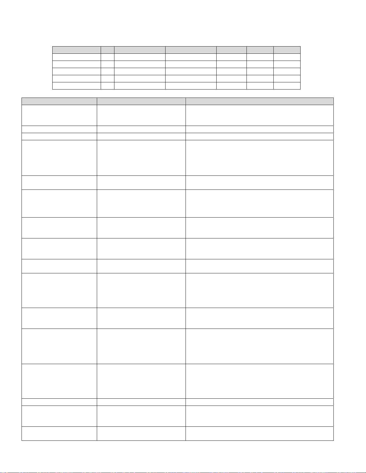
Please note that the model numberi n g system changed
March 2007. The chart below shows the old model
numbering system and its matching new model number.
Old Model Number
1116-080-A (or A1)
1116-062-8R
1116-023-8
1117-080-A (or A1)
1117-023-8
1130-080-A (or A1)
1130-08H-A
1131-080-A (or A1)
1131-08H-A
1132-080-A (or A1)
1132-08H-A
1132-002-8
1132-023-8
1133-080-A (or A1)
1133-08H-A
1161-080-A
1162-080-A
N/A
New Model Number
→
1116-00z-U-Kxxxx
→
1116-00z-U-Kxxxx
→
1116-00z-U-Kxxxx
→
1117-00z-U-Kxxxx
→
1117-00z-U-Kxxxx
→
1130-00z-U-Kxxxx
→
N/A
1131-00z-U-Kxxxx
→
N/A
1132-00z-U-Kxxxx
→
1172-00z-U-Kxxxx
→
1174-00z-U-Kxxxx
→
1132-00z-U-Kxxxx
→
1133-00z-U-Kxxxx
→
1173-00z-U-Kxxxx
→
1131-00z-U-Kxxxx
→
1132-00z-U-Kxxxx
→
1178-00z-U-Kxxxx
P/N: L371076
REV: 10.19.09
Lincoln Foodservice Products, LLC
1111 North Hadley Road
Fort Wayne, Indiana 46804
Telephone: 260.459.8200
Fax: 888.790.8193
Technical Support: 800.678.9511
lincolnfp.com
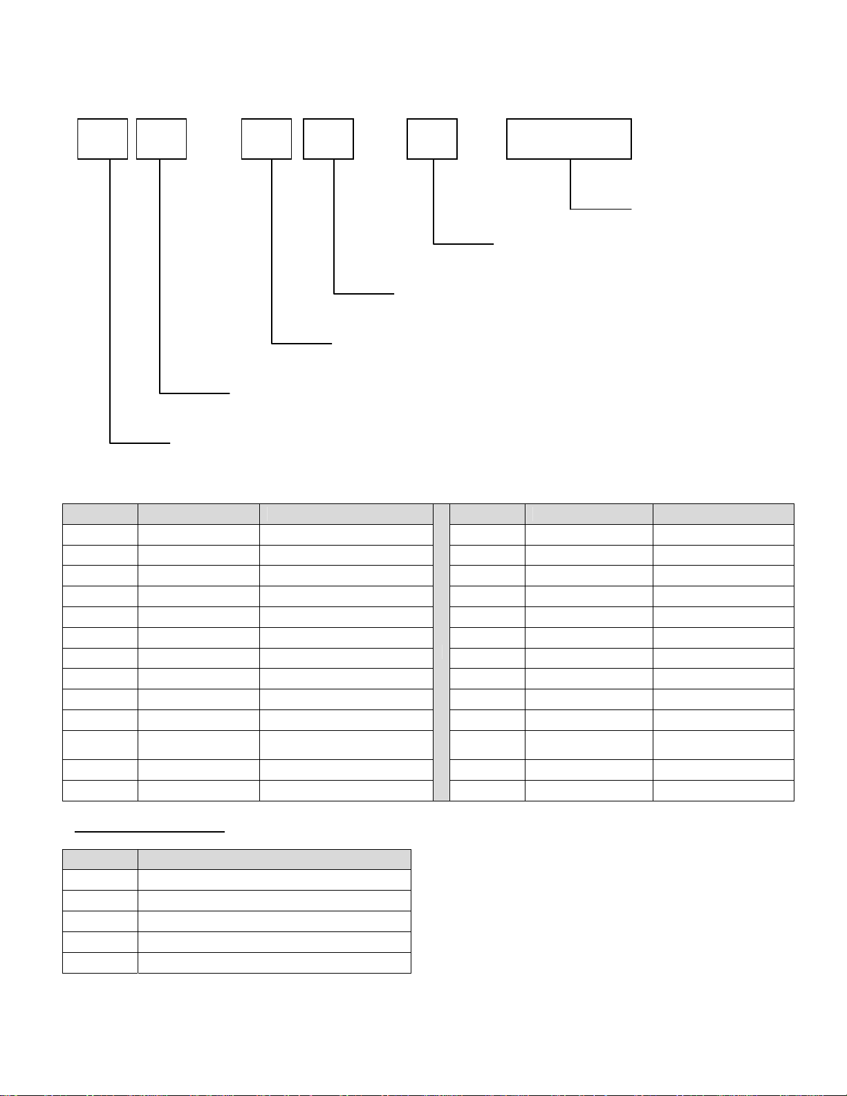
MODEL NUMBER KEY
EXAMPLE: 1116-B00-E-K1801
11 16 - B 00 - E - K1801
Agency Code (i.e. CE & RoHS combined)
Custom Configuration Code (i.e. General Market Version)
Language Code
Indicates change to base assembly (i.e. Natural Gas, 230V, 1 phase, 50 Hz)
Oven Platform Size (i.e. Impinger II)
CODE LANGUAGE COUNTRY CODE LANGUAGE COUNTRY
0 English Dom. & Int. Default N Finnish Finland
B French France/Luxembourg O Restricted ---
C German Germany P Norwegian Norway
D Italian Italy Q English Japan
E Span ish Spain R Swedish Sweden
F Engl ish UK/India/Africa/Hungary S English Australia
G Span ish Mexico/Latin America T Mandarin China
H Portuguese Portugal U Restricted ---
I Not Used --- V English Pacific Rim/Korea
J Danis h Denmark W English Middle East
K
L Dutch Netherlands Y Not Used ---
M Greek Greece Z Not Used ---
Dutch &
French
Belgium X Not Used ---
AGENCY CODE TABLE
CODE AGENCY
N No Agency
E CE & RoHS compliance combined
U US & Canada compliance only
A Advantage style oven to be phased-out
B Australia AGA
Panel Setup Code
2
Impinger II Express Service Manual - Domestic
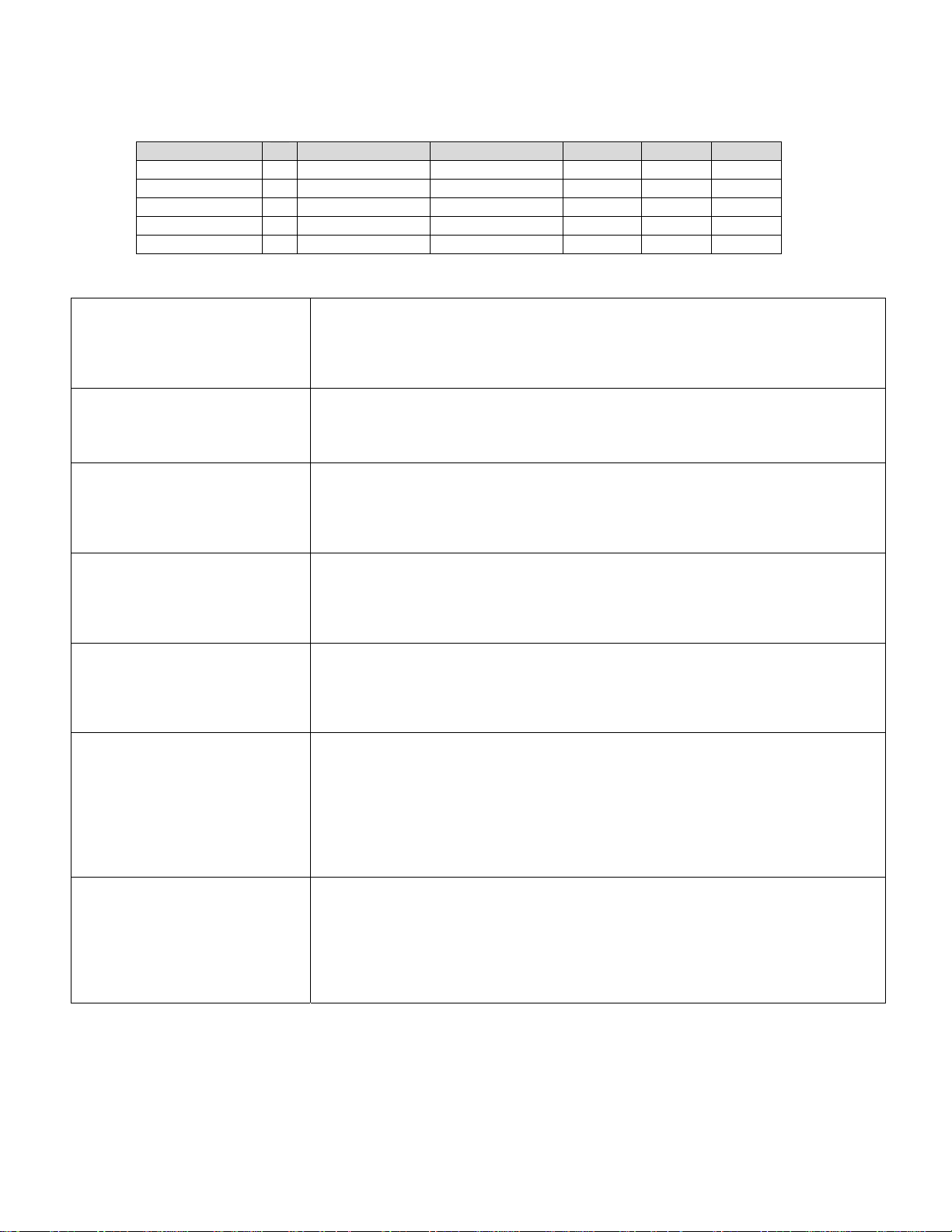
SEQUENCE OF OPERATION
IMPINGER II ADVANTAGE, GAS
(OVENS WITH PUSH BUTTON CONTROLS)
Old Model Number
1116-080-A (or A1)
1116-062-8R
1116-023-8
1117-080-A (or A1)
1117-023-8
New Model Number Gas Type Voltage Hz. Phase
→
1116-00z-U-Kxxxx Natural Gas 120 VAC 60 Hz. 1
→
1116-00z-U-Kxxxx Natural Gas 120 VAC 60 Hz. 1
→
1116-00z-U-Kxxxx Natural Gas 120 VAC 60 Hz. 1
→
1117-00z-U-Kxxxx LP Gas 120 VAC 60 Hz. 1
→
1117-00z-U-Kxxxx LP Gas 120 VAC 60 Hz. 1
→
POWER SUPPLY Electrical power is supplied to the oven by a three-conductor cordset. Voltage
from the black conductor to the white conductor is 120VAC.
Black conductor is hot
White conductor is neutral.
Green conductor is ground.
CONTROL BOX AUTO
COOL DOWN
When the temperature in the control box reaches 120°F ± 3° (48.9°C ± 1.7°), the
cooling fan thermostat will switch power to the control box cooling fans. The
thermostat will interrupt power to the cooling fans when the control box
temperature falls to 100°F ± 3° (37.8°C ± 1.7°).
MAIN FAN CIRCUIT Power is permanently supplied, through a 10 amp fuse, to the normally open
main power switch. Power is also supplied to the normally open cooling fan
thermostat. Closing the main power switch supplies 120VAC to the main fan
motor, the cooling fan motors, the primary of the control transformer, the
conveyor motor and to the ignition control.
BURNER CIRCUIT Closing the main power switch supplies 120VAC to the burner blower motor.
120VAC is also supplied, through the main fan centrifugal switch (this switch
closes when the main fan reaches approx. 1600 RPM) and the normally closed
oven cavity hi-limit thermostat, to the primary of the burner transformer. 120VAC
is also supplied to the oven control.
IGNITION CONTROL The ignition control operates on both 24VAC and 120VAC. When the control is
energized by 24VAC from the transformer, 120VAC is switched by the ignition
control to the hot surface igniter for 45 seconds for the hot surface igniter warm
up. The igniter glows red, 24VAC is switched to the gas valve, which opens, and
ignition should now occur.
TEMPERATURE CONTROL Closing the main power switch supplies 120VAC to the primary of the oven
control transformer. Secondary voltage, 24VAC, is supplied to the oven control.
The oven control is set to desired temperature. The thermocouple will provide
varying millivolts to the oven control. The oven control supplies 120VAC to the
temperature regulation valve at intermittent intervals to maintain the desired
temperature. The display on the oven control will indicate when the temperature
regulation valve is energized.
NOTE: The display also indicates oven temperature.
CONVEYOR DRIVE Closing the main power switch supplies 120VAC to the conveyor motor and to
the primary of the control transformer. Secondary voltage, 24VAC, is supplied to
the oven control. Setting the oven control to the desired time outputs voltage,
through a reversing switch, to the conveyor motor.
NOTE: The conveyor system uses a hall effect sensor and magnet to prove
operation of the conveyor motor. If the conveyor motor is not running, “BELT
JAM” is indicated on the display.
Impinger II Express Service Manual - Domestic
3
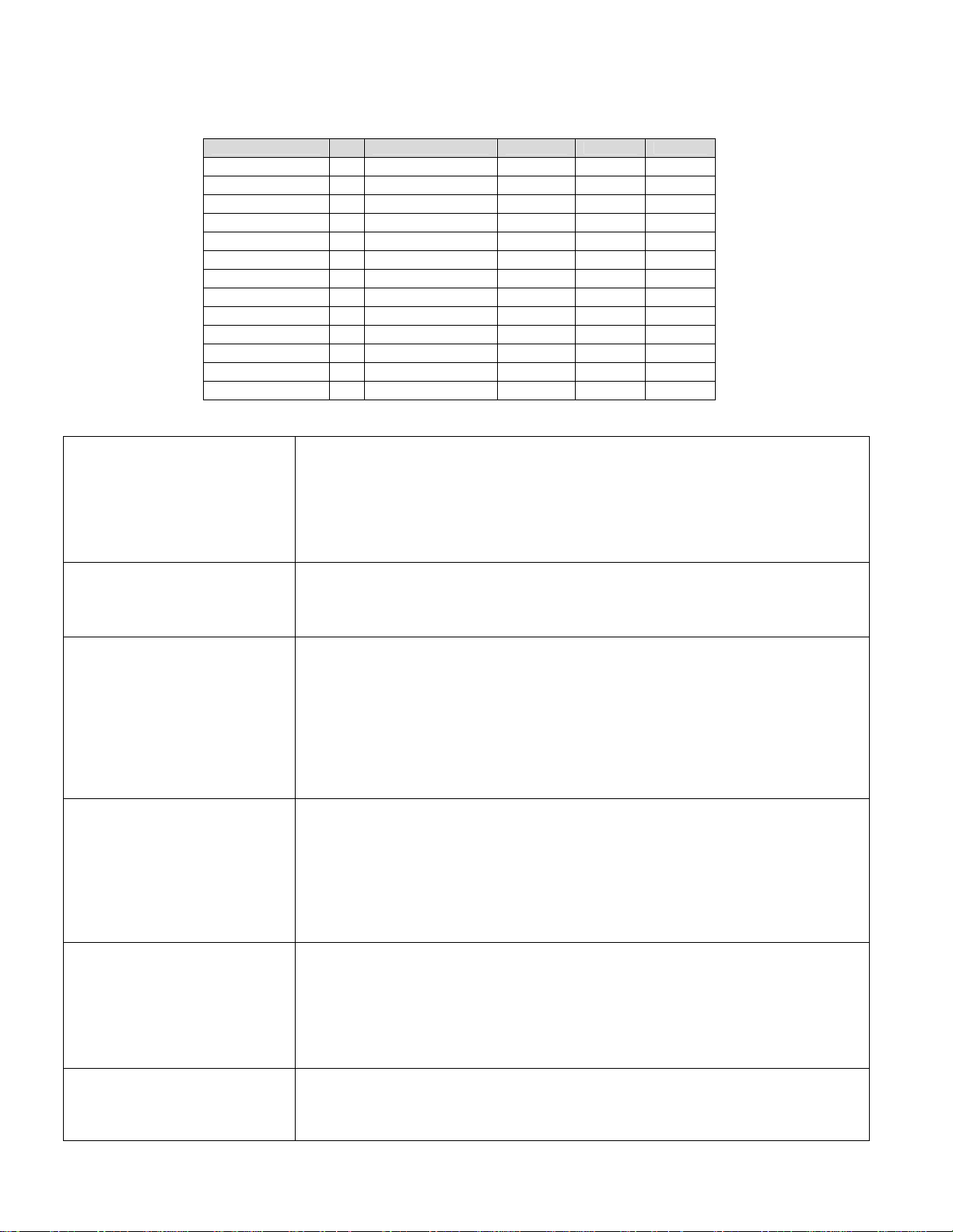
SEQUENCE OF OPERATION
IMPINGER II ADVANTAGE, ELECTRIC – S/N 0809210000016 & BELOW
(OVENS WITH PUSH BUTTON CONTROLS)
Old Model Number
1130-080-A (or A1)
1130-08H-A
1131-080-A (or A1)
1131-08H-A
1132-080-A (or A1)
1132-08H-A
1132-002-8
1132-023-8
1133-080-A (or A1)
1133-08H-A
1161-080-A
1162-080-A
N/A
POWER SUPPLY Electrical power to be supplied to the oven by a three conductor service for
single phase and a four conductor service for three phase.
Black conductor is hot.
Red conductor is hot.
Orange conductor is hot (used for three phase only).
White conductor is neutral.
Green conductor is ground.
CONTROL BOX AUTO
COOL DOWN
When the temperature in the control box reaches 120°F ± 3° (48.9°C ± 1.7°), the
cooling fan thermostat will switch power to the control box cooling fans. The
thermostat will interrupt power to the cooling fans when the control box
temperature falls to 100°F ± 3° (37.8°C ± 1.7°).
MAIN FAN CIRCUIT Power is permanently supplied through the 10 amp fuses, through the normally
closed oven cavity hi-limit thermostat, to the normally open main power switch.
Power is also supplied to the normally open cooling fan thermostat. Closing the
main power switch energizes the coil of the oven start relay, it’s contacts close
enabling the 20 minute time delay relay. The 20 minute time delay relay supplies
120VAC to the oven fan relay, these normally open contacts now close
supplying 208/240VAC to the main fan motor. 120VAC is also supplied to the
cooling fans. 208/240VAC is supplied to the primary of the control transformer,
the conveyor motor and, through the air pressure switch, to the oven control.
TEMPERATURE CONTROL Closing the main power switch supplies 208/240VAC to the primary of the
control transformer. Secondary voltage, 24VAC, is supplied to the oven control.
The oven control is set to desired temperature. The thermocouple will provide
varying millivolts to the oven control. The oven control supplies 208/240VAC to
the coil of the heater relay at intermittent intervals to maintain the desired
temperature. The display on the oven control will indicate when the heater relay
is energized.
NOTE: The display also indicates oven temperature.
CONVEYOR DRIVE Closing the main power switch supplies 208/240VAC to the conveyor motor and
to the primary of the control transformer. Secondary voltage, 24VAC, is supplied
to the oven control. Setting the oven control to the desired time outputs voltage,
through a reversing switch, to the conveyor motor.
NOTE: The conveyor system uses a hall effect sensor and magnet to prove
operation of the conveyor motor. If the conveyor motor is not running, “BELT
JAM” is indicated on the display.
AUTOMATIC COOL DOWN When the oven is started, the time delay relay timing circuit is enabled,
permitting the oven fans to run approximately 20 minutes after the oven is shut
off, to cool the oven. The time delay relay will keep the coil of the fan relay
closed, maintaining operation of the main fan and cooling fans.
New Model Number Voltage Hz. Phase
→
1130-00z-U-Kxxxx 120/ 208 60 Hz. 1
→
N/A 208 60 Hz. 1
→
1131-00z-U-Kxxxx 120/ 240 60 Hz. 1
→
N/A 240 60 Hz. 1
→
1132-00z-U-Kxxxx 120/ 208 60 Hz. 3
→
1172-00z-U-Kxxxx 208 60 Hz. 3
→
1174-00z-U-Kxxxx 208 50/60 Hz. 3
→
1132-00z-U-Kxxxx 208 50/60 Hz. 3
→
1133-00z-U-Kxxxx 120/ 240 60 Hz. 3
→
1173-00z-U-Kxxxx 240 60 Hz. 3
→
1131-00z-U-Kxxxx 120/ 240 60 Hz. 1
→
1132-00z-U-Kxxxx 120/ 208 60 Hz. 3
→
1178-00z-U-Kxxxx 120 60 Hz. 3
→
4
Impinger II Express Service Manual - Domestic

SEQUENCE OF OPERATION
IMPINGER II ADVANTAGE, ELECTRIC – S/N 0809210000017 & ABOVE
(OVENS WITH PUSH BUTTON CONTROLS)
Old Model Number
1130-080-A (or A1)
1130-08H-A
1131-080-A (or A1)
1131-08H-A
1132-080-A (or A1)
1132-08H-A
1132-002-8
1132-023-8
1133-080-A (or A1)
1133-08H-A
1161-080-A
1162-080-A
N/A
POWER SUPPLY Electrical power to be supplied to the oven by a three conductor service for
single phase and a four conductor service for three phase.
Black conductor is hot.
Red conductor is hot.
Orange conductor is hot (used for three phase only).
Green conductor is ground.
CONTROL BOX AUTO
COOL DOWN
When the temperature in the control box reaches 120°F ± 3° (48.9°C ± 1.7°), the
cooling fan thermostat will switch power to the control box cooling fans. The
thermostat will interrupt power to the cooling fans when the control box
temperature falls to 100°F ± 3° (37.8°C ± 1.7°).
MAIN FAN CIRCUIT Power is permanently supplied through the 10 amp fuses, through the normally
closed oven cavity hi-limit thermostat, to the normally open main power switch.
Power is also supplied to the normally open cooling fan thermostat. Closing the
main power switch energizes the coil of the cool down timer relay, its contacts
close enabling the 20 minute time delay relay. The 20 minute time delay relay
supplies 208/240VAC to the oven fan relay, these normally open contacts now
close supplying 208/240VAC to the main fan motor. 208/240VAC is also
supplied to the cooling fans. 208/240VAC is supplied to the primary of the control
transformer, the conveyor motor and, through the air pressure switch, to the
oven control.
TEMPERATURE CONTROL Closing the main power switch supplies 208/240VAC to the primary of the
control transformer. Secondary voltage, 24VAC, is supplied to the oven control.
The oven control is set to desired temperature. The thermocouple will provide
varying millivolts to the oven control. The oven control supplies 208/240VAC to
the coil of the heater relay at intermittent intervals to maintain the desired
temperature. The display on the oven control will indicate when the heater relay
is energized.
NOTE: The display also indicates oven temperature.
CONVEYOR DRIVE Closing the main power switch supplies 208/240VAC to the conveyor motor and
to the primary of the control transformer. Secondary voltage, 24VAC, is supplied
to the oven control. Setting the oven control to the desired time outputs voltage,
through a reversing switch, to the conveyor motor.
NOTE: The conveyor system uses a hall effect sensor and magnet to prove
operation of the conveyor motor. If the conveyor motor is not running, “BELT
JAM” is indicated on the display.
AUTOMATIC COOL DOWN When the oven is started, the time delay relay timing circuit is enabled,
permitting the oven fans to run approximately 20 minutes after the oven is shut
off, to cool the oven. The time delay relay will keep the coil of the fan relay
closed, maintaining operation of the main fan and cooling fans.
New Model Number Voltage Hz. Phase
→
1130-00z-U-Kxxxx 208 60 Hz. 1
→
N/A 208 60 Hz. 1
→
1131-00z-U-Kxxxx 240 60 Hz. 1
→
N/A 240 60 Hz. 1
→
1132-00z-U-Kxxxx 208 60 Hz. 3
→
1172-00z-U-Kxxxx 208 60 Hz. 3
1174-00z-U-Kxxxx 208 50/60 Hz. 3
1132-00z-U-Kxxxx 208 50/60 Hz. 3
1133-00z-U-Kxxxx 240 60 Hz. 3
1173-00z-U-Kxxxx 240 60 Hz. 3
1131-00z-U-Kxxxx 240 60 Hz. 1
1132-00z-U-Kxxxx 208 60 Hz. 3
1178-00z-U-Kxxxx 120 60 Hz. 3
Impinger II Express Service Manual - Domestic
5
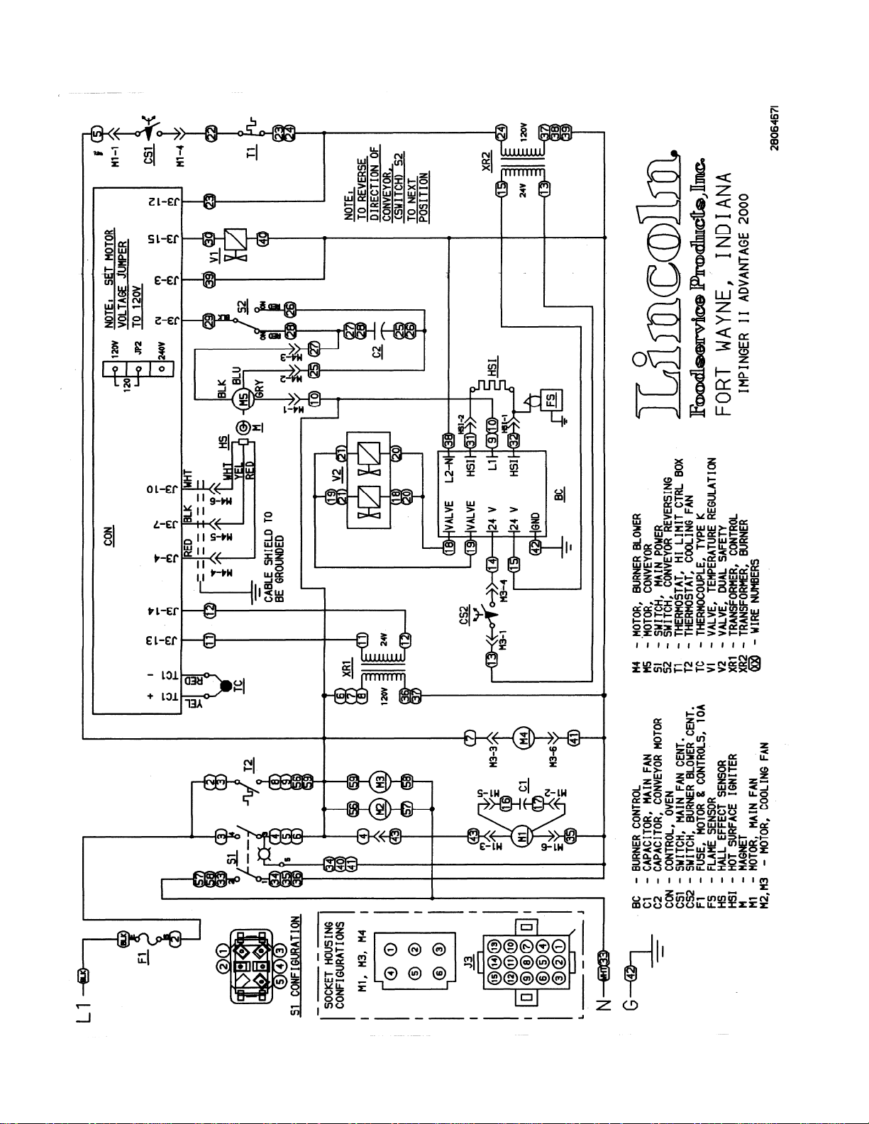
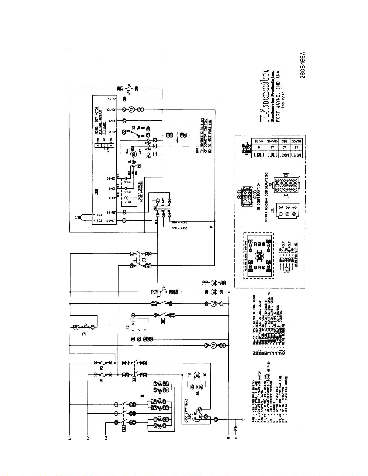
SCHEMATIC DIAGRAM
MODEL 1116-080-A, 1116-080-A1, 1117-080-A, 1117-080-A1
6
Impinger II Express Service Manual - Domestic
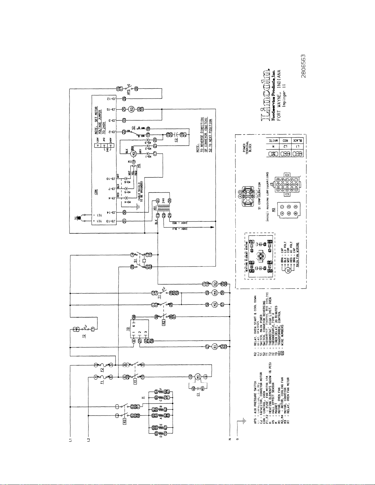
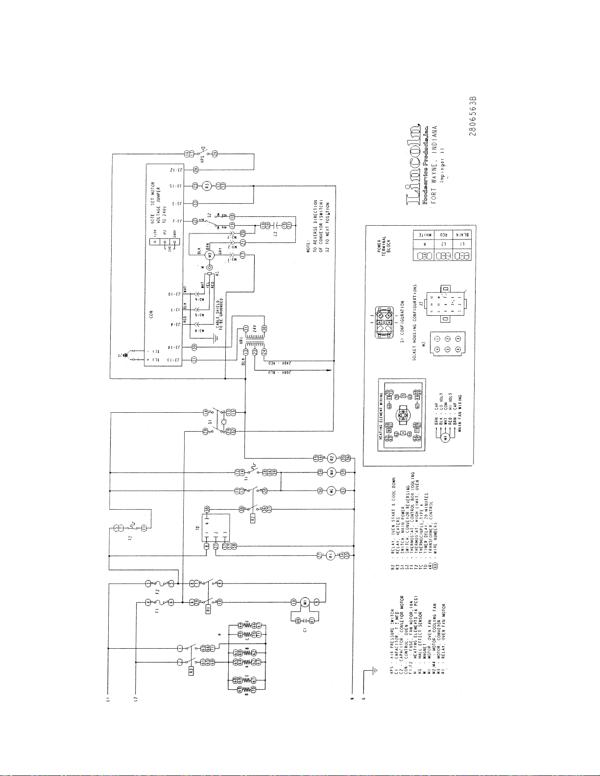
SCHEMATIC DIAGRAM
MODEL 1130-080-A, 1130-080-A1, 1131-080-A, 1131-080-A1
S/N 0809210000016 AND BELOW
Impinger II Express Service Manual - Domestic
7
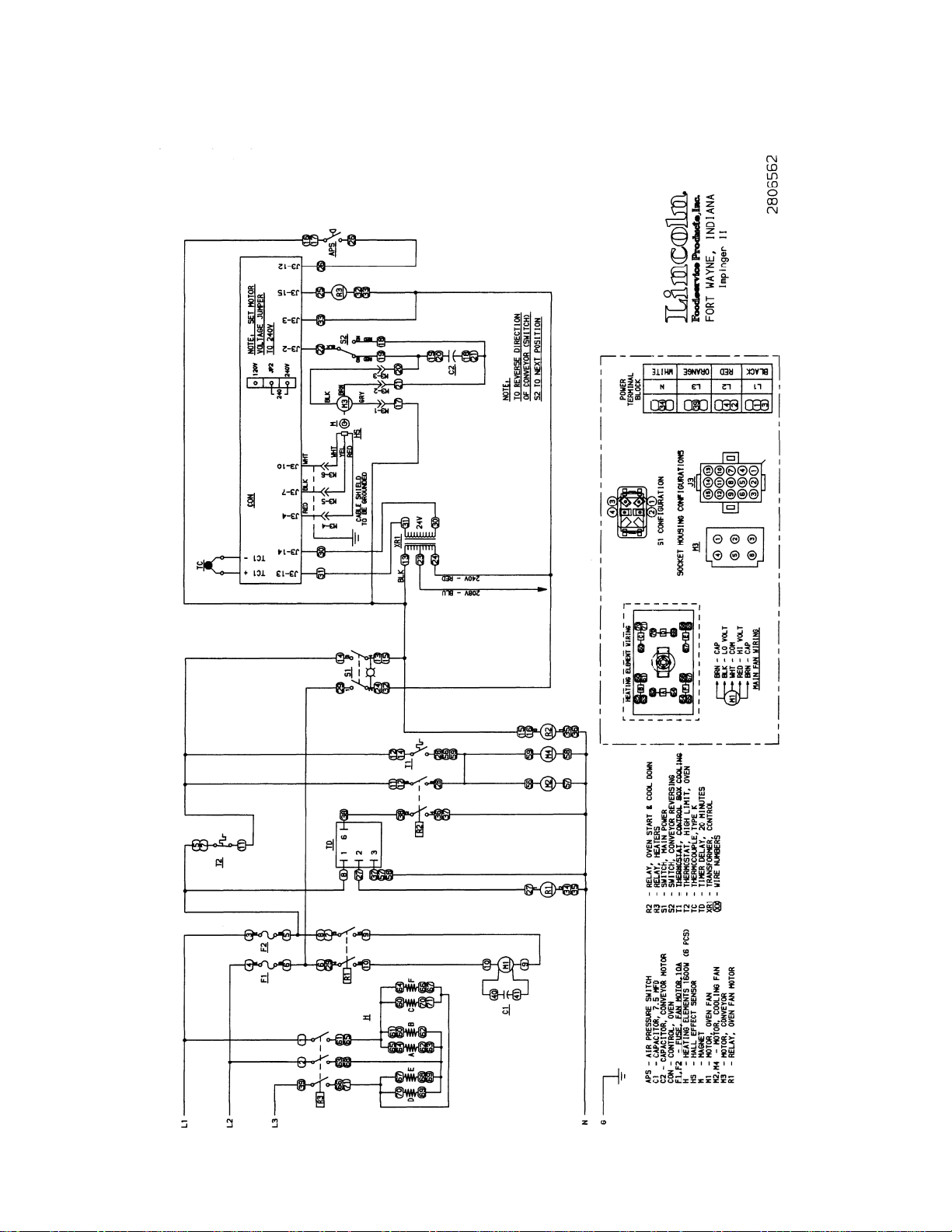
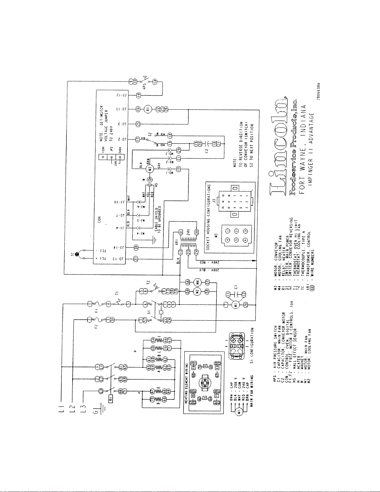
SCHEMATIC DIAGRAM
MODEL 1132-080-A, 1132-080-A1, 1133-080-A, 1133-080-A1
S/N 0809210000016 AND BELOW
8
Impinger II Express Service Manual - Domestic
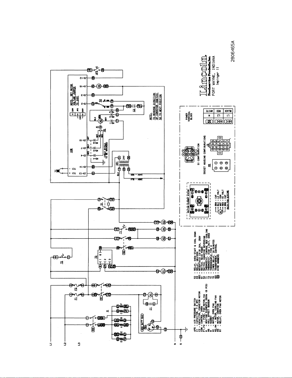
SCHEMATIC DIAGRAM
MODEL 1161-080-A
S/N 0809210000016 AND BELOW
Impinger II Express Service Manual - Domestic
9
SCHEMATIC DIAGRAM
MODEL 1162-080-A
S/N 0809210000016 AND BELOW
10
Impinger II Express Service Manual - Domestic
SCHEMATIC DIAGRAM
MODEL 1130-08H-A, 1131-08H-A
S/N 0809210000016 AND BELOW
Impinger II Express Service Manual - Domestic
11
SCHEMATIC DIAGRAM
MODEL 1132-08H-A, 1133-08H-A
S/N 0809210000016 AND BELOW
12
Impinger II Express Service Manual - Domestic
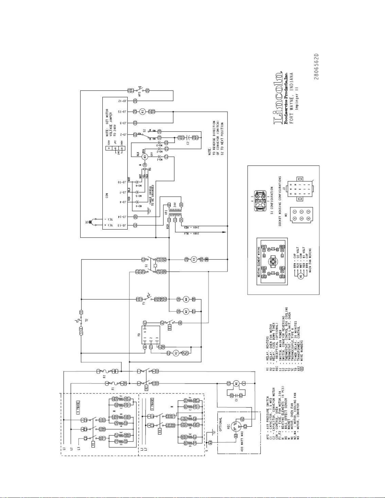
SCHEMATIC DIAGRAM
ALL MODELS
S/N 0809210000017 AND ABOVE
Impinger II Express Service Manual - Domestic
13
TROUBLESHOOTING GUIDE
GAS OVENS
Old Model Number
1116-080-A (or A1)
1116-062-8R
1116-023-8
1117-080-A (or A1)
1117-023-8
New Model Number Gas Type Voltage Hz. Phase
→
1116-00z-U-Kxxxx Natural Gas 120 VAC 60 Hz. 1
→
1116-00z-U-Kxxxx Natural Gas 120 VAC 60 Hz. 1
→
1116-00z-U-Kxxxx Natural Gas 120 VAC 60 Hz. 1
→
1117-00z-U-Kxxxx LP Gas 120 VAC 60 Hz. 1
→
1117-00z-U-Kxxxx LP Gas 120 VAC 60 Hz. 1
→
SYMPTOM POSSIBLE CAUSE EVALUATION
Oven fan will not run Incoming power supply Check circuit breakers, reset if required. Check
power plug to be sure it is firmly in receptacle.
Measure incoming power, call power co. if needed.
Fuse, 10 Amp Check, replace if necessary.
Fuse holder Check, replace if necessary.
Hi-limit thermostat,
control box
Switch, main power Check continuity between switch terminals. Replace
Main fan motor Check for 120VAC at motor. If no voltage is present,
Capacitor Check for shorts or grounds.
No control box cooling Incoming power Check circuit breakers, reset if required. Check
Switch, main power Check continuity between switch terminals. Replace
Cooling fan Check for 120VAC at cooling fan. If no voltage is
No automatic control box
Incoming power supply Check circuit breakers, reset if required. Check
cooling
Cooling fan thermostat Check the cooling fan thermostat. (Thermostat
Cooling fan Check for 120VAC at cooling fan. If no voltage is
Oven will not heat Gas supply Check for adequate gas supply to oven.
Manual gas shut off valve. Check to see that the manual gas shut off valve is
Main fan If not operating, refer to “Oven fan will not run”.
Check for voltage on both sides of switch. Terminals
are normally closed. If open, reset and test oven for
proper operation. If thermostat will not hold, and
control box temperature is not exceeding 140°F
(60°C), replace thermostat.
switch as needed.
trace wiring back to main power switch.
WITH POWER OFF: Check for opens, shorts or
grounds. Turn fan blade to check for locked rotor.
WARNING: Capacitor has a stored charge,
discharge before testing.
power plug to be sure it is firmly in receptacle.
Measure incoming power, call power co. if needed.
switch as needed.
present, trace wiring back to power switch. If voltage
is present, and motor does not run, check for opens,
shorts or grounds.
WITH POWER OFF: Check for locked rotor.
power plug to be sure it is firmly in receptacle.
Measure incoming power, call power co. if needed.
closes at 120°F and opens at 100°F). With the
cooling fan thermostat pre-heated, check for
continuity. If switch is open, replace cooling fan
thermostat.
present, trace wiring back to cooling fan thermostat.
If voltage is present, and motor does not run, check
for opens, shorts or grounds.
WITH POWER OFF: Check for locked rotor.
open. Also check flexible gas line connection for any
damage.
14
Impinger II Express Service Manual - Domestic

Centrifugal switch of main fan
motor
Check for 120VAC at wire #5 (input to centrifugal
switch, located at 6-pin connector in raceway near
the main fan motor) to neutral. If no voltage is
present, trace wiring back to the main power switch.
If voltage is present, check for 120VAC at wire #22
(output of centrifugal switch) to neutral. If no voltage
is present at #22, and the motor is running, replace
the main fan motor.
Hi-limit thermostat,
oven cavity
Terminals are normally closed. If open, reset
thermostat and retest. If thermostat will not hold for
maximum oven temperature, and oven is not
exceeding temperature setting, check for proper
location of capillary bulb in its spring holder. If the
capillary checks okay, replace the hi-limit thermostat.
Burner blower motor Check for 120VAC supplied to burner blower motor
at wire #13 to neutral. If no voltage is present, trace
wiring back to the main power switch. If voltage is
present, and the motor is not running, check for
opens, shorts or grounds.
WITH POWER OFF: Turn motor to check for locked
rotor.
Burner transformer Check for 120VAC supplied to the primary of the
burner transformer. If no voltage is present, trace
wiring back to the oven cavity hi-limit thermostat. If
voltage is present, check for 24VAC at transformer
secondary. If there is primary voltage but no
secondary voltage, replace burner transformer.
Centrifugal switch of burner
blower motor
Check for 24VAC at motor connector, wire #13 to
neutral. If voltage is not present, trace wiring back to
transformer. If voltage is present, check for voltage at
wire #14 to neutral. If no voltage is present at wire
#14, and motor is running, replace burner blower
motor.
Ignition control Check for 24VAC at ignition control terminals marked
“24V”, if no voltage is present, trace wiring back to
centrifugal switch. Check for 120VAC to ignition
control at terminal “L1” to neutral. If no voltage is
present, trace wiring back to main power switch.
When 24VAC is supplied to the ignition control, the
ignition control switches 120VAC to the hot surface
igniter If 24VAC and 120VAC are supplied to ignition
control, but there is no voltage at the hot surface
igniter, replace the ignition control.
Hot surface igniter If 120VAC is present at hot surface igniter terminals,
visually check to see that the igniter is heating
(igniter may be viewed through the port in the end of
burner tube). The igniter should glow bright red. If the
igniter does not heat, replace the hot surface igniter.
Ignition control After 45 seconds of hot surface igniter pre-heat, the
ignition control will switch 24VAC to the gas control
valves. Check for 24VAC output from ignition control
across terminals marked “valve” and “valve gnd”. If
no voltage is present, replace ignition control.
Gas control valves When 24VAC is supplied to the gas control valves,
the valve should open. Check for gas pressure at the
manifold tap located just before the burner. If there is
no pressure, check the incoming gas supply to be
sure all manual valves are open and flexible gas
hose is properly connected. If gas is present, and the
gas control valve is energized, but there is no gas
pressure at the burner manifold, replace the gas
Impinger II Express Service Manual - Domestic
15

control valves.
Flame will not stay lit Hot surface igniter Six seconds after the gas valve opens, ignition must
occur. If flame is not detected, the ignition control will
shut off and lock out. To reset the ignition control,
turn off the power switch for 45 seconds, then turn
the switch on to re-try ignition. The ignition control
requires a minimum of 0.8 DC microamps to prove
flame. To check flame sensing operation, connect a
digital multimeter (capable of measuring DC
microamps) between the “ground” terminal on
ignition control and the ground lead.
NOTE: This is a current measurement and the meter
must be connected in series
If these readings are not achieved, replace hot
surface igniter.
NOTE: The DC microamp test must be conducted
with the oven in low flame (bypass) operation. Set
the temperature control to the lowest setting.
Power supply If there is sufficient microamp current, but the flame
will not stay lit, check for proper polarity of the
120VAC power supply.
Ignition control If there is sufficient microamp current, and the
120VAC polarity is correct, but the flame will not stay
lit, replace the ignition control.
NOTE: Check for proper ground connection on
ignition control.
NOTE: Flame should be on at
this time
Low flame is on,
but no main flame
Control transformer Check for 120VAC supply to the primary of the
control transformer. If no voltage is present, trace
wiring back to the main power switch. If voltage is
present, check for 24VAC at the transformer
secondary. If there is primary voltage, but no
secondary voltage, replace the control transformer.
Oven control Check for 24VAC supply to control. If no voltage is
present, trace wiring back to control transformer. If
24VAC is present, check for a read-out on the
display. If there is 24VAC supplied, but there is no
read-out on the control display, replace the oven
control.
If there is a read-out on the control, set the control to
maximum temperature (see installation operations
manual for temperature adjustment). With the control
set at maximum temperature, check for 120VAC at
the temperature regulation valve. If there is voltage at
the temperature regulation valve, proceed to
“Temperature regulation valve” for next check. If
there is no voltage at the temperature regulation
valve, trace wiring back to the oven control. If there is
no voltage output at the oven control, check the read-
out on the control. If the control reads “PROBE
FAIL”, this indicates that the thermocouple has failed
or become disconnected from the oven control.
Thermocouple Check to be sure that the thermocouple is securely
connected to the oven control. If the thermocouple is
connected to the oven control, and the control
indicates “PROBE FAIL”, disconnect the
thermocouple from the oven control and measure the
resistance of the thermocouple. The thermocouple
should read approx. 11Ω. If these readings are not
16
Impinger II Express Service Manual - Domestic

achieved, replace the thermocouple. If these
readings are correct, proceed.
Oven control If the thermocouple checks good, but the oven
control display indicates that there is a thermocouple
failure, replace the oven control. If the oven control
indicates a temperature reading but the oven won’t
heat, proceed.
Thermocouple WITH POWER ON AND THERMOCOUPLE
ATTACHED TO THE OVEN CONTROL: Measure
the DC millivolt output of the thermocouple. Refer to
the thermocouple chart (located in the “Removal”
section of the manual) for proper millivolt readings. If
these readings are not achieved, replace
thermocouple.
Oven control If the thermocouple checks good, but there is no
120VAC output to the temperature regulation valve,
replace the oven control. If there is 120VAC output to
the temperature regulation valve, proceed.
Temperature regulation valve Check for 120VAC supplied to temperature
regulation valve. If voltage is present, listen for valve
to open and close. Also check for opens or shorts in
the operating coil. Replace temperature regulation
valve as needed.
Intermittent heating Thermal/overload of main fan
and burner blower motors
The main fan motor and burner blower motor are
equipped with internal thermal protection and will
cease to operate if overheating occurs. As the
motors overheat and then cool, this will cause the
heating system to cycle on and off intermittently.
Improper ventilation or lack of preventive
maintenance may cause this problem. Also, most of
the problems listed under “Oven will not heat” can
cause intermittent failure.
Conveyor will not run Power supply Check for incoming voltage at line 1 to neutral. There
should be a reading of 120VAC. If not present, check
circuit breakers.
Fuse, 10 Amp Check, replace if necessary.
Fuse holder Check, replace if necessary.
Hi-limit thermostat, control box Check for voltage on both sides of switch. Terminals
are normally closed. If open, reset and test oven for
proper operation. If thermostat will not hold, and
control box temperature is not exceeding 140°F
(60°C), replace thermostat.
Power switch Check continuity between switch terminals. Replace
switch as needed.
Control transformer Check for 120 VAC supply to the primary of the
control transformer. If no voltage is present, trace
wiring back to the oven power relay. If voltage is
present, check for 24 VAC at the transformer
secondary. If there is primary voltage but no
secondary voltage, replace control transformer.
Conveyor motor Check for 120 VAC supply to the conveyor motor at
wire #14 to neutral. If no voltage is present, trace
wiring back to the primary of the control transformer.
If voltage is present and the motor will not run, check
the motor windings for opens or shorts.
WITH POWER OFF: Check the motor windings as
follows:
Grey to black - 38Ω approx.
Grey to blue - 38Ω approx.
Blue to black - 75Ω approx.
Impinger II Express Service Manual - Domestic
17

If any of the above fails, replace conveyor motor.
Capacitor, conveyor motor Check for shorts or grounds. Replace capacitor as
needed.
WARNING: Capacitor has a stored charge,
discharge before testing.
Switch, conveyor reversing Check continuity between switch terminals. Replace
switch as needed.
Oven control If there is 120VAC supplied to the motor, and the
motor, capacitor, and reversing switch check good,
replace the oven control.
Conveyor motor runs, but
there is no speed display
NOTE: Display will indicate
“Belt Jam”
Oven control Check for output voltage from oven control to hall
effect sensor (sensor is located in conveyor motor).
Measure voltage at the motor connector, red wire
and yellow wire. Voltage should be approx. 10VDC. If
no voltage is present, trace wiring back to oven
control. If there is no voltage present at the oven
control, replace the oven control.
Conveyor motor If there is voltage supplied to the hall effect sensor,
check for a frequency output from the hall effect
sensor. Measure frequency across the yellow and
white wires at the motor connector. Frequency
reading should be approx. 25 – 100 Hz. If these
readings are not achieved, replace conveyor motor. If
the readings are achieved, proceed.
Oven control If the hall effect sensor readings are correct, but
there is no speed indicated on the display, replace
the oven control.
18
Impinger II Express Service Manual - Domestic

TROUBLESHOOTING GUIDE
ELECTRIC OVENS
Old Model Number
1130-080-A (or A1)
1130-08H-A
1131-080-A (or A1)
1131-08H-A
1132-080-A (or A1)
1132-08H-A
1132-002-8
1132-023-8
1133-080-A (or A1)
1133-08H-A
1161-080-A
1162-080-A
N/A
New Model Number Voltage Hz. Phase
→
1130-00z-U-Kxxxx 208 60 Hz. 1
→
N/A 208 60 Hz. 1
→
1131-00z-U-Kxxxx 240 60 Hz. 1
→
N/A 240 60 Hz. 1
→
1132-00z-U-Kxxxx 208 60 Hz. 3
→
1172-00z-U-Kxxxx 208 60 Hz. 3
→
1174-00z-U-Kxxxx 208 50/60 Hz. 3
→
1132-00z-U-Kxxxx 208 50/60 Hz. 3
→
1133-00z-U-Kxxxx 240 60 Hz. 3
→
1173-00z-U-Kxxxx 240 60 Hz. 3
→
1131-00z-U-Kxxxx 240 60 Hz. 1
→
1132-00z-U-Kxxxx 208 60 Hz. 3
→
1178-00z-U-Kxxxx 120 60 Hz. 3
→
SYMPTOM POSSIBLE CAUSE EVALUATION
Oven fan will not run Incoming power supply Check circuit breakers. Reset if required. Call
power co. if needed.
Fuses, 10 Amp, motor and
controls
Fuse holder Check, replace if necessary.
Hi-limit thermostat,
Oven cavity
Switch, main power Check continuity between switch terminals.
Relay, oven start Check for 208 or 240VAC supplied to coil of relay.
20 minute time delay Check for 208 or 240VAC at terminal #1 to L2 on
Relay, main fan Check for 208 or 240VAC to coil of main fan relay.
Main fan motor Check for supply voltage at motor. If no voltage is
Capacitor Check for shorts or grounds.
No main fan cool down 20 Minute time delay Check for 208 or 240VAC at terminal #2 to neutral
Check, replace if necessary.
Terminals are normally closed. If open, reset
thermostat and retest. If thermostat will not hold
for maximum oven temperature, and oven is not
exceeding temperature setting, check for proper
location of capillary bulb in its spring holder. If the
capillary checks okay, replace the hi-limit
thermostat.
Replace switch as needed.
If no voltage is present, trace wiring back to main
power switch. If voltage is present, check for pull
in of relay contacts. Replace relay as needed.
time delay relay. If voltage is not present, trace
wiring back to 10A fuse. If voltage is present at
terminal #1, check for 208/240VAC at terminal #2
to L2. If no voltage is present, and oven start relay
is closed, replace 20 minute time delay relay.
If no voltage is present, trace wiring back to 20
minute time delay relay. If voltage is present,
check to insure that relay contacts are closing.
Replace relay as needed.
present, trace wiring back to main fan relay.
WITH POWER OFF: Check for opens, shorts or
grounds. Turn fan blade to check for locked rotor.
WARNING: Capacitor has a stored charge,
discharge before testing.
while the oven is ‘on’. Turn off the main switch,
208 or 240VAC should continue to be present for
20 minutes. If voltage is not present for approx. 20
Impinger II Express Service Manual - Domestic
19

minutes, replace the 20 minute time delay.
Oven fan relay Check for 208 or 240VAC to relay coil, if no
voltage is present, trace wiring back to 20 minute
time delay. If voltage is present, be sure that relay
contacts stay closes during the 20 minute cool
down. Replace relay as needed.
Main fan runs after
20 minute cool down
Oven start relay Contacts should open when main power switch is
turned off. Replace relay as needed.
20 Minute time delay 208 or 240VAC at terminal #2 should discontinue
approx. 20 minutes after main power is switched
off. If the oven start relay contacts are open, and
the voltage continues at terminal #2 of the 20
minute timer, for more than 20 minutes, replace
the 20 minute time delay.
Oven fan relay Check to insure that the relay contacts are
opening after the relay coil is de-energized.
Replace relay as needed.
20 Minute time delay NOTE: On/ off operation of the main power switch
will set the timer to 20 minutes. If the timer is
accidentally reset, turn off the main circuit breaker
for 15 seconds to cancel.
No control box cooling Incoming power Check circuit breakers, reset if required. Check
power plug to be sure it is firmly in receptacle.
Measure incoming power, call power co. if
needed.
Switch, main power Check continuity between switch terminals.
Replace switch as needed.
Cooling fan Check for supply voltage at cooling fan. If no
voltage is present, trace wiring back to power
switch. If voltage is present, and motor does not
run, check for opens, shorts or grounds.
WITH POWER OFF: Check for locked rotor.
No automatic control box
cooling
Incoming power supply Check circuit breakers, reset if required. Check
power plug to be sure it is firmly in receptacle.
Measure incoming power, call power co. if
needed.
Cooling fan thermostat Check the cooling fan thermostat. (Thermostat
closes at 120°F and opens at 100°F). With the
cooling fan thermostat pre-heated, check for
continuity. If switch is open, replace cooling fan
thermostat.
Cooling fan Check for supply voltage at cooling fan. If no
voltage is present, trace wiring back to cooling fan
thermostat. If voltage is present, and motor does
not run, check for opens, shorts or grounds.
WITH POWER OFF: Check for locked rotor.
Oven will not heat Main fan motor Check for main fan operation. If it is not operating,
refer to “Oven fan will not run”.
Air pressure switch This normally open switch should close when the
main fan is activated. Refer to the “Removal and
installation” section for proper adjustment.
Replace as needed.
Control transformer Check for 208 or 240VAC supply to the primary of
the control transformer. If no voltage is present,
trace wiring back to the main power switch. If
voltage is present, check for 24VAC at the
transformer secondary. If there is primary voltage,
but no secondary voltage, replace the control
transformer.
Oven control Check for 24VAC supply to control. If no voltage is
20
Impinger II Express Service Manual - Domestic

present, trace wiring back to control transformer. If
24VAC is present, check for a read-out on the
display. If there is 24VAC supplied, but there is no
read-out on the control display, replace the oven
control.
If there is a read-out on the control, set the control
to maximum temperature (see installation
operations manual for temperature adjustment).
With the control set at maximum temperature,
check for supply voltage at mercury contactor. If
there is voltage at the mercury contactor, proceed
to “mercury contactor” for next check. If there is no
voltage at the mercury contactor, trace wiring back
to the oven control. If there is no voltage output at
the oven control, check the read-out on the
control. If the control reads “PROBE FAIL”, this
indicates that the thermocouple has failed or
become disconnected from the oven control.
Thermocouple Check to be sure that the thermocouple is
securely connected to the oven control. If the
thermocouple is connected to the oven control,
and the control indicates “PROBE FAIL”,
disconnect the thermocouple from the oven
control and measure the resistance of the
thermocouple. The thermocouple should read
approx. 11Ω. If these readings are not achieved,
replace the thermocouple. If these readings are
correct, proceed.
Oven control If the thermocouple checks good, but the oven
control display indicates that there is a
thermocouple failure, replace the oven control. If
the oven control indicates a temperature reading
but the oven will not heat, proceed.
Thermocouple WITH POWER ON AND THERMOCOUPLE
ATTACHED TO THE OVEN CONTROL: Measure
the DC millivolt output of the thermocouple. Refer
to the thermocouple chart (located in the
“Removal” section of the manual) for proper
millivolt readings. If these readings are not
achieved, replace thermocouple.
Oven control If the thermocouple checks good, but there is no
voltage output to the mercury contactor, replace
the oven control. If there is voltage output to the
mercury contactor, proceed.
Mercury contactor Check for supply voltage to the contactor coil. If
voltage is present and the contactor will not
activate, replace the mercury contactor. Also
check each contactor for high voltage input and
output.
Heating element(s) Check the Amp draw on each power leg for proper
load. Check the specification plate for rating
information. If the amp draw is high or low, check
the individual elements for opens, shorts and
proper resistance.
WITH POWER OFF: To check resistance of the
elements, remove all leads from the elements and
use a digital multimeter.
The element resistance is should be as follows:
208V – 27 ohms approx.
240V – 36 ohms approx.
Replace heating elements as needed.
Impinger II Express Service Manual - Domestic
21

Oven heats with switch off Mercury contactor The mercury contactor has probably failed in the
closed position. If there is no voltage to the
operating coil, but there is high voltage at the
contactor output, replace the mercury contactor.
Intermittent heating Thermal/overload of motor The main fan motor is equipped with internal
thermal protection and will cease to operate if
overheating occurs. As the motor overheats and
then cools, this will cause the oven to cycle on and
off intermittently. Improper ventilation or lack of
preventive maintenance may cause this. Also,
most of the problems listed under “Oven will not
heat” can cause intermittent failure.
Conveyor will not run Power supply Check circuit breakers, reset if required. Check
power plug to be sure it is firmly in receptacle.
Measure incoming power, call power co. if
needed.
Fuse, 10 Amp Check, replace if necessary.
Fuse holder Check, replace if necessary.
Hi-limit thermostat, oven cavity Terminals are normally closed. If open, reset
thermostat and retest. If thermostat will not hold
for maximum oven temperature, and oven is not
exceeding temperature setting, check for proper
location of capillary bulb in its spring holder. If the
capillary checks okay, replace the hi-limit
thermostat.
Power switch Check continuity between switch terminals.
Replace switch as needed.
Control transformer Check for supply voltage to the primary of the
control transformer. If no voltage is present, trace
wiring back to the oven power relay. If voltage is
present, check for 24 VAC at the transformer
secondary. If there is primary voltage but no
secondary voltage, replace control transformer.
Conveyor motor Check for supply voltage to the conveyor motor. If
no voltage is present, trace wiring back to the
primary of the control transformer. If voltage is
present and the motor will not run, check the
motor windings for opens or shorts.
WITH POWER OFF: Check the motor windings as
follows:
Grey to black - 240Ω approx.
Grey to tan - 240Ω approx.
Tan to black - 480Ω approx.
If any of the above fails, replace conveyor motor.
Capacitor, conveyor motor Check for shorts or grounds. Replace capacitor as
needed.
WARNING: Capacitor has a stored charge,
discharge before testing.
Switch, conveyor reversing Check continuity between switch terminals.
Replace switch as needed.
Oven control If there is supply voltage to the motor, and the
motor, capacitor, and reversing switch check
good, replace the oven control.
Conveyor motor runs, but
there is no speed display
NOTE: Display will indicate
“Belt Jam”
Oven control Check for output voltage from oven control to hall
effect sensor (sensor is located in conveyor
motor). Measure voltage at the motor connector,
22
Impinger II Express Service Manual - Domestic

red wire and yellow wire. Voltage should be
approx. 10VDC. If no voltage is present, trace
wiring back to oven control. If there is no voltage
present at the oven control, replace the oven
control.
Conveyor motor If there is voltage supplied to the hall effect
sensor, check for a frequency output from the hall
effect sensor. Measure frequency across the
yellow and white wires at the motor connector.
Frequency reading should be approx. 25 – 100
Hz. If these readings are not achieved, replace
conveyor motor. If the readings are achieved,
proceed.
Oven control If the hall effect sensor readings are correct, but
there is no speed indicated on the display, replace
the oven control.
REMOVAL, INSTALLATION AND ADJUSTMENTS
IMPINGER II ADVANTAGE SERIES
CAUTION
BEFORE REMOVING OR INSTALLING ANY COMPONENT IN THE IMPINGER
OVEN BE SURE TO DISCONNECT ELECTRICAL POWER AND GAS SUPPLY.
MAIN FAN – REPLACEMENT
A. Shut off power at main breaker.
B. Remove motor cover from back of oven.
C. Disconnect wiring and mark for reassembly.
D. Remove bolts and slide back straight out of the oven.
E. Loosen the bolt from fan hub and remove fan from motor shaft.
NOTE: Measure distance from fan blade to rear wall assembly before removal to aid in reassembly.
F. Reassemble in reverse order and check system operation.
MOTOR, MAIN FAN – REPLACEMENT
A. Shut off power at main breaker.
B. Remove motor cover from back of oven.
C. Disconnect wiring and mark for reassembly.
D. Remove bolts and slide back straight out of the oven.
E. Loosen the bolt from fan hub and remove fan from motor shaft.
NOTE: Measure distance from the fan blade to rear wall assembly before removal to aid in reassembly.
F. Remove four screws from motor support assembly.
G. Remove motor mount clamp and remove motor from oven back.
H. Remove motor mount from motor.
I. Reassemble in reverse order and check system operation.
Impinger II Express Service Manual - Domestic
23

CAPACITOR – REPLACEMENT
A. Shut off power at main breaker.
B. Remove rear control box cover.
C. Disch arge capacitor.
D. Remov e capacitor.
E. Reassemble in reverse order and check system operation.
ON/OFF SWITCH – REPLACEMENT
A. Shut off power at main breaker.
B. Remove conveyor and front control box cover.
C. Depress spring clips on sides of switch and push out.
D. Remove wires from switch and mark for reassembly.
E. Reassemble in reverse order and check system operation.
NOTE: Make sure switch housing is fully seated in control box housing.
FUSE HOLDER – REPLACEMENT
A. Shut off power at main breaker.
B. Remove rear control box cover.
C. Remove wires from fuse holder and mark for reassembly.
D. Remove mounting screws or mounting nut on fuse holder and remove fuse holder.
E. Reassemble in reverse order and check system operation.
COOLING FAN, CONTROL BOX – REPLACEMENT
A. Shut off power at main breaker.
B. Remove appropriate control box cover and conveyor if necessary.
C. Remove four mounting screws from fan frame.
D. Disconnect power cord and remove fan.
E. Reassemble in reverse order and check system operation. Check for air flow.
THERMOSTAT, COOLING FAN, REPLACEMENT
A. Shut off power at main breaker.
B. Remove conveyor and front control box cover.
C. Remove wires and mark for reassembly.
D. Remove two mounting screws and remove thermostat.
E. Reassemble in reverse order and check system operation.
BURNER BLOWER MOTOR – REPLACEMENT
A. Shut off power at main breaker.
B. Remove rear control box cover.
C. Unplug motor connector.
D. Remove three mounting screws from blower tube at burner housing.
E. Remove air shutter assembly from old motor for assembly on new motor.
F. Reassemble in reverse order and check system operation.
NOTE: Check air shutter at approximately ½ open and adjust to get a blue flame with an occasional
tip of yellow under high flame. A view port in the burner assembly should be used to observe flame.
HI-LIMIT THERMOSTAT, OVEN CAVITY – REPLACEMENT
A. Shut off power at main breaker.
B. Remove conveyor and bottom finger assembly. Remove rear control box cover.
C. Remove capillary bulb from bracket in oven chamber and pull capillary tube through tube into
control box.
D. Remove all wires and mark for reassembly.
E. Remove mounting nut and remove thermostat.
24
Impinger II Express Service Manual - Domestic

F. Reassemble in reverse order and check system operation. Be sure capillary tube is securely in
the mount.
NOTE: Push reset button on new thermostat.
TRANSFORMER, BURNER – REPLACEMENT
A. Shut off power at main breaker.
B. Remove conveyor and front control box cover.
C. Remove all wires from transformer and mark for reassembly.
D. Remove two mounting screws from transformer base and remove transformer.
E. Reassemble in reverse order and check system operation.
OVEN CONTROL – REPLACEMENT
A. Shut off power at main breaker.
B. Remove conveyor and front control box cover.
C. Remove all wiring connections and mark for reassembly.
D. Remove oven control by pulling control from the mounting pins. Remove control from oven.
E. Before installing new oven control, set voltage jumper (located at the bottom center of the oven
control) to the proper voltage (120V/240V) position. Set frequency jumper to the proper
frequency (50Hz/60Hz). Install the four pushbutton extensions (included with the oven control)
by pushing the extensions onto the four set buttons on control.
F. Reassemble in reverse order and check system operation.
G. Set the oven control for the proper operating mode. The 1100 series ovens use a single
temperature control system. The oven control must be set to the proper operating mode. Set the
control as follows: With the oven power switch “off”, depress the “time” and “up” buttons and turn
the oven “on”. Control will indicate ”Imp I or Imp II” Release the buttons, The control will indicate
“Temp to store”. Press the “up” or “down” button until “Imp II” appears on the display. Press the
“temp” button. The control is now set for single burner operation.
TRANSFORMER – CONTROL – REPLACEMENT
See “TRANSFORMER –BURNER - REPLACEMENT
THERMOCOUPLE – REPLACEMENT
A. Shut off power at main breaker.
B. Remove conveyor and bottom finger assembly.
C. Remove front control box cover.
D. Remove thermocouple from bracket in oven chamber and pull thermocouple through tube into
control box.
E. Remove two thermocouple wires from temperature control. Note wire color and location for
reassembly
F. Reassemble in reverse order and check system operation
THERMOCOUPLE MEASUREMENT
TEMPERATURE (°F) D.C. MILLIVOLTS
200 ° 2.8
250 ° 4.0
300 ° 5.1
350° 6.0
400 ° 7.1
450 ° 8.2
500 ° 9.3
550 ° 10.4
600 ° 11.5
Impinger II Express Service Manual - Domestic
25

BURNER CONTROL – REPLACEMENT
A. Shut off power at main breaker.
B. Remove conveyor and front control box cover.
C. Remove wires from control and mark for reassembly.
D. Remove mounting screws from control and remove burner control.
E. Reassemble in reverse order and check system operation.
GAS VALVE – REPLACEMENT
A. Shut off power at main breaker.
B. Shut off gas supply to the oven and disconnect the flexible gas line to oven.
C. Remove rear control box cover.
D. Remove the manual gas shut-off valve.
E. Remove screws from the bulkhead plate on inlet gas pipe and remove inlet gas pipe.
F. Remove pilot tube and wiring from gas valve, Mark all wiring for reassembly.
G. Disconnect pipe union in gas line and remove gas valve and piping assembly.
H. Remove piping from gas valve.
I. Reassemble in reverse order and check system operation.
J. Check all gas line fitting for leaks.
K. Adjust the gas manifold pressure on the gas valve. Refer to the specification plate on the oven
for proper rating.
TEMPERATURE REGULATION VALVE – REPLACEMENT
A. Shut off power at main breaker.
B. Shut off gas supply to the oven and disconnect the flexible gas line to oven.
C. Remove rear control box cover.
D. Remove bypass tube from burner manifold.
E. Remove wiring from valve and mark for reassembly.
F. Remove four mounting nuts from burner manifold and disconnect pipe union.
G. Remove temperature regulation valve and piping from oven.
HOT SURFACE IGNITER – REPLACEMENT
A. Shut off power at main breaker.
B. Shut off gas supply to the oven and disconnect the flexible gas line to oven.
C. Remove conveyor and control box covers.
D. Remove temperature regulation valve. See “TEMPERATURE REGULATION VALVE”.
E. Disconnect wires from burner control.
F. Remove three mounting screws and remove burner venturi.
G. Remove mounting nut and remove hot surface igniter assembly.
H. Reassemble in reverse order and check system operation.
I. Check all gas line fittings for leaks.
26
Impinger II Express Service Manual - Domestic

BYPASS ORIFICE – REPLACEMENT
A. Shut off power at main breaker.
B. Shut off gas supply to the oven and disconnect the flexible gas line to oven.
C. Remove rear control box cover.
D. Disconnect bypass tube from gas valve.
E. Remove bypass orifice from gas valve.
F. Reassemble in reverse order and check system operation.
G. Check all gas line fittings for leaks.
MAIN BURNER ORIFICE – REPLACEMENT
A. Shut off power at main breaker.
B. Shut off gas supply to the oven and disconnect the flexible gas line to oven.
C. Remove rear control box cover.
D. Remove burner manifold. See “TEMPERATURE REGULATION VALVE”.
E. Remove main burner orifice from burner manifold.
F. Reassemble in reverse order and check system operation.
G. Check all gas line fittings for leaks.
REVERSING SWITCH – REPLACEMENT
A. Shut off power at main breaker.
B. Remove rear control box cover.
C. Remove wires from reversing switch and mark for reassembly.
D. Remove mounting nut and remove switch.
E. Reassemble in reverse order and check system operation.
CONVEYOR DRIVE MOTOR – REPLACEMENT
A. Shut off power at main breaker.
B. Remove conveyor and both control box covers.
C. Disconnect all wiring from motor and mark for reassembly.
D. Remove coupling from motor drive shaft.
E. Remove four screws and remove conveyor motor and mounting bracket.
F. Remove mounting bracket from conveyor motor.
G. Reassemble in reverse order and check system operation.
REVERSING CONVEYOR DIRECTION
A. Shut off power at oven switch.
B. Set conveyor reversing switch in the other position.
C. Turn oven “on” and check for proper operation.
CAPACITOR, CONVEYOR DRIVE MOTOR – REPLACEMENT
A. Shut off power at main breaker.
B. Remove rear control box cover.
C. Discharge capacitor before removing wires. Mark wires for reassembly.
D. Remove mounting screw and remove capacitor.
E. Reassemble in reverse order and check system operation.
AIR PRESSURE SWITCH – REPLACEMENT
A. Shut off power at main breaker.
B. Remove conveyor and front control box cover.
C. Disconnect wiring from air pressure switch and mark for reassembly.
D. Disconnect air tube from air pressure switch.
E. Remove two mounting screws and remove air pressure switch.
F. Reassemble in reverse order and check system operation. Be sure to calibrate new air pressure
switch. For proper calibration, see below.
Impinger II Express Service Manual - Domestic
27

G. Turn adjusting screw on air pressure switch fully counter clockwise.
H. Turn oven “on”.
I. Turn adjusting screw on air pressure switch clockwise until heat shuts off.
J. Turn adjusting screw on air pressure switch counter clockwise ¼ turn.
K. Reassemble control panel top and front cover.
BEARING, CONVEYOR – REPLACEMENT
A. Remove conveyor from oven and place on a flat work surface.
B. Remove connecting links from conveyor belt. See Installation Operations manual for proper
procedure. Remove conveyor belt from conveyor.
C. Move drive shaft or idler shaft toward end of conveyor, and shaft with bearing will now slip out of
conveyor frame.
D. Remove bearing from conveyor shaft.
E. Reassemble in reverse order and check system operation.
MERCURY CONTACTOR – REPLACEMENT
A. Shut off power at main breaker.
B. Remove rear control box cover.
C. Disconnect all wires and mark for reassembly.
D. Remove screws from mounting bracket and remove contactor.
E. Reassemble in reverse order and check system operation.
HEATING ELEMENT – REPLACEMENT
A. Shut off power at main breaker.
B. Remove back cover.
C. Disconnect heating element wires and mark for reassembly.
D. Disconnect motor wiring and mark for reassembly.
E. Remove oven back from oven.
F. Remove fan shroud.
G. Heating element may now be unbolted and removed.
H. Check new heating element for proper voltage. Reassemble in reverse order and check for
proper operation.
28
Impinger II Express Service Manual - Domestic

This page intentionally left blank.
Impinger II Express Service Manual - Domestic
29

GENERAL VIEW
Old Model Number
1116-080-A (or A1)
1116-062-8R
1116-023-8
1117-080-A (or A1)
1117-023-8
1130-080-A (or A1)
1130-08H-A
1131-080-A (or A1)
1131-08H-A
1132-080-A (or A1)
1132-08H-A
1132-002-8
1132-023-8
1133-080-A (or A1)
1133-08H-A
1161-080-A
1162-080-A
N/A
→
→
→
→
→
→
→
→
→
→
→
→
→
→
→
→
→
→
→
New Model Number
1116-00z-U-Kxxxx
1116-00z-U-Kxxxx
1116-00z-U-Kxxxx
1117-00z-U-Kxxxx
1117-00z-U-Kxxxx
1130-00z-U-Kxxxx
N/A
1131-00z-U-Kxxxx
N/A
1132-00z-U-Kxxxx
1172-00z-U-Kxxxx
1174-00z-U-Kxxxx
1132-00z-U-Kxxxx
1133-00z-U-Kxxxx
1173-00z-U-Kxxxx
1131-00z-U-Kxxxx
1132-00z-U-Kxxxx
1178-00z-U-Kxxxx
LETTER PART NUMBER DESCRIPTION
A* 370412 Cross support
B* 370416 Stand side
C* 369231 Caster, 4” w/threaded stem
D* 369232 Adjustable leg
E 369390 Caster, 4” w/mounting plate
F Oven Door, See “Conveyor / Door View” Section
G 370010 Bottom finger housing
H 369502 Bottom finger cover
I
J
K 370415 Oven top
L
M 371066 Baffle
N 369211 Thumb screw
O
P
* A new stand was designed and implemented on March 16, 2009. Parts are not compatible between old
and new stand styles. See Addendum A in the back of this manual for a parts breakdown and assembly
instructions.
369504 Top finger housing (model ending with –080-A)
370487 Top finger housing (model ending with –080-A1)
369503 Top finger cover (model ending with –080-A)
370486 Top finger cover (model ending with –080-A1)
369659 Conveyor hole cover (S/N 2052462 & below)
370679 Conveyor hole cover (S/N 2052463 & above)
Columnating plate, see Installation & Operations
manual
Columnating plate, see Installation & Operations
manual
30
Impinger II Express Service Manual - Domestic

GENERAL VIEW
Impinger II Express Service Manual - Domestic
31

Old Model Number
1116-080-A (or A1)
1116-062-8R
1116-023-8
1117-080-A (or A1)
1117-023-8
LETTER PART NUMBER DESCRIPTION
A 369805 Switch, on/off
B 370408 Facia, pushbutton
C
D 369531 Transformer, 24VAC
E 369507 Thermostat, cooling fan
F 369124 Cooling fan
G 369532 Ignition control
H
I 369680 Front cover assy.
370417 Contro l board
370409 Displ ay only
370410 Stand off Plate (SN 0903210000317 & Below)**
369856 Stand off Support (SN 0903210000318 & Above)**
** This pertains to all non-TU units.
CONTROL BOX, FRONT
→
→
→
→
→
→
New Model Number
1116-00z-U-Kxxxx
1116-00z-U-Kxxxx
1116-00z-U-Kxxxx
1117-00z-U-Kxxxx
1117-00z-U-Kxxxx
32
Impinger II Express Service Manual - Domestic

CONTROL BOX, FRONT VIEW
Old Model Number
1116-080-A (or A1)
1116-062-8R
1116-023-8
1117-080-A (or A1)
1117-023-8
→
→
→
→
→
→
New Model Number
1116-00z-U-Kxxxx
1116-00z-U-Kxxxx
1116-00z-U-Kxxxx
1117-00z-U-Kxxxx
1117-00z-U-Kxxxx
Impinger II Express Service Manual - Domestic
33

CONTROL BOX, FRONT
Old Model Number
1130-080-A (or A1)
1130-08H-A
1131-080-A (or A1)
1131-08H-A
1132-080-A (or A1)
1132-08H-A
1132-002-8
1132-023-8
1133-080-A (or A1)
1133-08H-A
1161-080-A
1162-080-A
N/A
→
→
→
→
→
→
→
→
→
→
→
→
→
LETTER PART NUMBER DESCRIPTION
A 369680 Front cover assy.
B
C 369432 On/off switch
D 370408 Facia, push button
E
F 369427 Transformer, control
G 369507 Thermostat, cooling fan
H
I
J
K
369508 Timer, 20-minute (S/N 0809210000016 & below)
370466 Timer, 20-minute (S/N 0809210000017 & above)
370417 Contro l Board
370409 Displ ay only
369124 Cooling Fan (S/N 0809210000016 & below)
369378 Cooling Fan (S/N 0809210000017 & above)
369523 Relay, Oven Start (S/N 0809210000016 & below)
369422 Relay, Oven Start (S/N 0809210000017 & above)
369025 Air pressure switch, Johnson
370673 Air Pressure Switch, Gold Tech
370410 Stand-off Plate Assy (SN 0903210000317 & Below)**
369856 Stand off Support (SN 0903210000318 & Above)**
New Model Number
1130-00z-U-Kxxxx
N/A
1131-00z-U-Kxxxx
N/A
1132-00z-U-Kxxxx
1172-00z-U-Kxxxx
1174-00z-U-Kxxxx
1132-00z-U-Kxxxx
1133-00z-U-Kxxxx
1173-00z-U-Kxxxx
1131-00z-U-Kxxxx
1132-00z-U-Kxxxx
1178-00z-U-Kxxxx
** This pertains to all non-TU units.
34
Impinger II Express Service Manual - Domestic

CONTROL BOX, FRONT VIEW
Old Model Number
1130-080-A (or A1)
1130-08H-A
1131-080-A (or A1)
1131-08H-A
1132-080-A (or A1)
1132-08H-A
1132-002-8
1132-023-8
1133-080-A (or A1)
1133-08H-A
1161-080-A
1162-080-A
N/A
→
→
→
→
→
→
→
→
→
→
→
→
→
New Model Number
1130-00z-U-Kxxxx
N/A
1131-00z-U-Kxxxx
N/A
1132-00z-U-Kxxxx
1172-00z-U-Kxxxx
1174-00z-U-Kxxxx
1132-00z-U-Kxxxx
1133-00z-U-Kxxxx
1173-00z-U-Kxxxx
1131-00z-U-Kxxxx
1132-00z-U-Kxxxx
1178-00z-U-Kxxxx
Impinger II Express Service Manual - Domestic
35

CONTROL BOX, REAR
Old Model Number
1116-080-A (or A1)
1116-062-8R
1116-023-8
1117-080-A (or A1)
1117-023-8
→
→
→
→
→
→
New Model Number
1116-00z-U-Kxxxx
1116-00z-U-Kxxxx
1116-00z-U-Kxxxx
1117-00z-U-Kxxxx
1117-00z-U-Kxxxx
LETTER PART NUMBER DESCRIPTION
A 369192 Capacitor
B
C 369901 Burner manifold
D
E
F 369552 Hot surface igniter
G 369398 Valve, temperature regulation
H 370359 Reversing switch, conveyor
I 369366 Burner blower motor
J 369401 Air shutter assy.
K
L 369263 Gas valve, Nat./L.P.
M 357067 Thermostat, oven cavity hi-limit
N
O 369129 Fuse holder
P 370362 Thermocouple, type ”K”
Q 369682 Control box cover, rear
R 369166 Fuse, 10A.
S 369331 Finger guard
T 369124 Cooling Fan
U 370364 Ground lug
V 369537 Power cord
370378 Conveyor motor assy. (S/N 2052462 & below)
370675 Conveyor motor assy. (S/N 2052463 & above)
369568 Burner venturi, Nat. gas
369938 Burner venturi, L.P. gas
369566 Orifice, main, Nat. gas
369524 Orifice, main, L.P. gas
369556 Orifice, bypass, Nat. gas
369557 Orifice, bypass, L.P. gas
370376 Capacitor, conveyor motor (S/N 2052462 & below)
370681 Capacitor, conveyor motor (S/N 2052463 & above)
36
Impinger II Express Service Manual - Domestic

CONTROL BOX, REAR VIEW
Old Model Number
1116-080-A (or A1)
1116-062-8R
1116-023-8
1117-080-A (or A1)
1117-023-8
→
→
→
→
→
→
New Model Number
1116-00z-U-Kxxxx
1116-00z-U-Kxxxx
1116-00z-U-Kxxxx
1117-00z-U-Kxxxx
1117-00z-U-Kxxxx
Impinger II Express Service Manual - Domestic
37

38
CONTROL BOX REAR
Old Model Number
1130-080-A (or A1)
1130-08H-A
1131-080-A (or A1)
1131-08H-A
1132-080-A (or A1)
1132-08H-A
1132-002-8
1132-023-8
1133-080-A (or A1)
1133-08H-A
1161-080-A
1162-080-A
N/A
→
→
→
→
→
→
→
→
→
→
→
→
→
New Model Number
1130-00z-U-Kxxxx
N/A
1131-00z-U-Kxxxx
N/A
1132-00z-U-Kxxxx
1172-00z-U-Kxxxx
1174-00z-U-Kxxxx
1132-00z-U-Kxxxx
1133-00z-U-Kxxxx
1173-00z-U-Kxxxx
1131-00z-U-Kxxxx
1132-00z-U-Kxxxx
1178-00z-U-Kxxxx
LETTER PART NUMBER DESCRIPTION
A 369192 Capacitor
B
C
D 370362 Thermocouple, Type “K”
E
F
G 369682 Control box cover, rear
H 357067 Thermostat, oven cavity hi-limit
I 370359 Reversing switch, conveyor
J 370302 Receptacle
K 369129 Fuse holder
L
M
N 369331 Finger guard
O 369166 Fuse, 10A.
P 370364 Ground lug
Q 370134 Electrical Box Cover
R 370133 Electrical Box
369200 Relay, Main Fan (S/N 0809210000016 & below)
369422 Relay, Main Fan (S/N 0809210000017 & above)
369124 Cool ing Fan
369378 Cooling Fan (S/N 0809210000017 & above)
369185 Terminal block section 1 Phase (2 required)
369187 Terminal block section (3 required)
369186 Terminal block end 1 Phase
369188 Terminal block end 3 Phase
370067 Mercury contactor 2 pole (1 Phase)
369479 Mercury contactor 3 pole (3 Phase)
370485 Mercury contactor 3 pole (3 Phase) – “08H-A” model only
370383 Capacitor, conveyor motor (S/N 2052462 & below)
370382 Capacitor, conveyor motor (S/N 2052463 & above)
370384 Conveyor motor (S/N 2052462 & below)
370676 Conveyor motor (S/N 2052463 & above)
Impinger II Express Service Manual - Domestic

CONTROL BOX, REAR VIEW
Old Model Number
1130-080-A (or A1)
1130-08H-A
1131-080-A (or A1)
1131-08H-A
1132-080-A (or A1)
1132-08H-A
1132-002-8
1132-023-8
1133-080-A (or A1)
1133-08H-A
1161-080-A
1162-080-A
N/A
→
→
→
→
→
→
→
→
→
→
→
→
→
New Model Number
1130-00z-U-Kxxxx
N/A
1131-00z-U-Kxxxx
N/A
1132-00z-U-Kxxxx
1172-00z-U-Kxxxx
1174-00z-U-Kxxxx
1132-00z-U-Kxxxx
1133-00z-U-Kxxxx
1173-00z-U-Kxxxx
1131-00z-U-Kxxxx
1132-00z-U-Kxxxx
1178-00z-U-Kxxxx
Impinger II Express Service Manual - Domestic
39

OVEN BACK ASSEMBLY
ALL MODELS
LETTER PART NUMBER DESCRIPTION
A 369182 Fan
B 369899 Fan shroud
C 369655 Stand off
Heating Elements
369183 208 Volt
369184 240 Volt
D
E
369581 Motor mount
G
H 369695 Bracket, motor
I 369033 Clamp, motor
J 369681 Cover, back
K 369979 Bracket, hi-limit
L 369227 Spring
M 369541 Bracket, thermocouple
370648 208 Volt – Models 1130-08H-A & 1132-08H-A (S/N 10062053640 & below)
370645 240 Volt – Models 1131-08H-A & 1133-08H-A (S/N 10062053640 & below)
370690 208 Volt – Models 1130-08H-A & 1132-08H-A (S/N 10062053641 & above)
370689 240 Volt – Models 1131-08H-A & 1133-08H-A (S/N 10062053641 & above)
369976 Rear wall – Gas Ovens
369549 Rear wall – Electric Ovens
Rear wall for the following models:
1132-08H-A
Motor
369539 Gas ovens (120VAC)
369181 Electric ovens (208/240VAC)
1172-000-U
1130-08H-A
1170-000-U
40
Impinger II Express Service Manual - Domestic

OVEN BACK ASSEMBLY VIEW
ALL MODELS
Impinger II Express Service Manual - Domestic
41

CONVEYOR / DOOR
ALL MODELS
LETTER PART NUMBER DESCRIPTION
A
B 369512 Coupling center (S/N 2052462 & below)
C 369269 Ball plunger (S/N 2052462 & below)
D 370116 Set screw (S/N 2052462 & below)
E 369223
F 369224 Crumb pan, left (S/N 2045452 & below)
G 369666 Conveyor frame assembly
H 369226 Pan stop
J 369516 Conveyor bearing
K 369514 Idler shaft
L
M
N 369513 Hinge
O 370413 Door assembly
P 370016 Impinger nameplate
Q 369501 Door latch & catch
R 370414 Door assembly with window
S 369927 Window frame, top (NLA – See Access Door Section)
T 369925 Glass, access window (NLA – See Access Door Section)
U 369926 Window frame, bottom (NLA – See Access Door Section)
W 369929 Retainer, window (See Access Door Section)
X 369165 Splice clip, conveyor belt
Y
Not Shown 369471 Roll Pin
*** 369222 Complete Conveyor Assy (S/N 2052462 & below)
*** 370677 Complete Conveyor Assy (S/N 2052463 & above)
369190 Coupler (S/N 2052462 & below)
370671 Coupler (S/N 2052463 & above)
Crumb pan, right (S/N 2045452 & below)
Crumb pan, right and left (S/N 2045453 & above)
369515 Sprocket (includes set screw), Regular Conveyor
369978 Set screw
370509 Sprocket (includes set screw), Heavy-Duty Conveyor
369238 Drive shaft (S/N 2052462 & below)
370678 Drive shaft (S/N 2052463 & above)
369194 Conveyor belt (complete), Regular Conveyor
369394 Conveyor belt (1-Foot section), Regular Conveyor
370155 Conveyor Belt (complete), Heavy-Duty Conveyor
370157 Conveyor Belt (1-Foot Section), Heavy-Duty Conveyor
*** Complete Conveyor Assembly includes letters A, G, J, K, L, M, X, and Y.
42
Impinger II Express Service Manual - Domestic

CONVEYOR / DOOR VIEW
ALL MODELS
Impinger II Express Service Manual - Domestic
43

ACCESS DOOR
ALL MODELS (SN 0908210000875 AND BELOW)
LETTER PART NUMBER DESCRIPTION
369110 Access Door Assembly
A 370724 Extrusion
B 369928 Dowel, Access Door
C 370726 Bracket Assembly
D 370725 Dowel Thread
E 370727 Bracket Assembly
F 370723 Glass
Not Shown 369929 Retainer, Window
E
A
B
C
D
44
Impinger II Express Service Manual - Domestic

STAINLESS STEEL ACCESS DOOR
ALL MODELS (SN 0908210000875 AND ABOVE)
LETTER PART NUMBER DESCRIPTION
369110 Access Door Assembly
A 371140 Bracket Assembly, Left
B 371142 Dowel, Access Door
C 370722 Screw
D 371143 8-32 x 3/8 Hx Serr Flng
E 371141 Bracket Assembly, Right
F 370725 Dowel Thread
G 371144 Access Door Frame (top or bottom)
H 370723 Glass
H
A
B
C
D
E
G
F
Impinger II Express Service Manual - Domestic
45

ADDENDUM A
NEW STYLE OVEN STAND (BEGINNING MARCH 16, 2009)
1. Insert the four Stand Side Bars (G) into the four holes located on each of the Front/Back Assemblies (A). Note: The Stand Side Bar that
contains labels should be facing “out” so that the labels can be easily read by the operator.
2. Attach the Stand Side Bars to the Front/Back Assemblies and tighten using the 1 ¾” Hexagon Bolts (B), Washers (E) and Acorn Nuts (D)
provided. Two sets each of the bolts, washers and nuts are to be used at each intersection of Stand Side Bars and Front Back Assemblies
for a total of 16 sets.
3. Select Caster or Adjustable Leg and screw into nutsert in the bottom corner of each Front/Back Stand Assembly. Tighten Casters securely.
4. Set assembled Stand on casters/legs in an open, clear area and lock casters, as applicable, in preparation for mounting oven on stand.
5. When placing the oven on the stand, align the bolt holes located in the Front/Back Stand Assemblies with the holes located in the bottom of
the oven. With holes in alignment, insert the 2 ½” Hexagon Bolts and tighten to secure the oven to Stand (Fig. 2).
!
CAUTION:
USE EXTREME CARE IN STEP #5 TO INSURE OVEN DOESN’T SLIP OFF STAND BEFORE BOLTS HAVE
SECURED OVEN TO STAND.
HARDWARE PROVIDED FOR STAND ASSEMBLY
LETTER PART # DESCRIPTION
A 90000799 Front / Back Stand Assemblies
B 000151SP Hexagon Bolt (1 ¾”)
C 369231 Caster, 4”
D 2133001 Acorn Nut
E 000821SP Washer
F 369233 Hexagon Bolt (2 ½” )
G 10004656 Stand Side Bar
H Adjustable Leg for 1127-1 stand
Not Shown 9002533
Not Shown Hexagon Bolt (1/2”) for double-stack oven configuration
Shelf for 1127-1 stand
E
D
G
A
F
C
B
46
H
Impinger II Express Service Manual - Domestic

This page intentionally left blank.
Impinger II Express Service Manual - Domestic
47

48
Impinger II Express Service Manual - Domestic
 Loading...