

Lincoln 1100 User Manual
INSTALLATION & OPERATING
INSTRUCTIONS
for
IMPINGER® II CONVEYOR OVENS
ADVANTAGE CONVEYOR OVENS
MODEL SERIES 1100
TO BE SERVICED ONLY BY AUTHORIZED PERSONS
1100opsman REV: 4/3/07
Part Number: 2810075

WARNING AND SAFETY INFORMATION
FOR YOUR SAFETY, DO NOT STORE OR USE GASOLI
NE OR OTHER FLAMMABLE VAPORS OR LIQUIDS
DO NOT SPRAY AEROSOLS IN THE VICINITY OF THIS APPLIANCE WHILE IT IS IN OPERATION.
WARNING: IMPROPER INSTALLATION, ADJUSTMENT, ALTERATION, SERVICE OR MAINTENANCE CAN
IMPORTANT
IN THE VICINITY OT THIS OR ANY OTHER APPLIANCE.
CAUSE PROPERTY DAMAGE, INJURY OR DEATH. READ THE INSTALLATION, OPERATING, AND
MAINTENANCE INSTRUCTIONS THOROUGHLY BEFORE INSTALLING OR SERVICING THIS EQUIPMENT.
· Obtain from your local gas provider and post in a prominent location instructions to be followed in the event gas
odors are detected.
· It is required that the oven be placed under a ventilation hood to provide for adequate air supply and ventilation.
· Minimum clearances must be maintained from all walls and combustible materials. See spacing instruction on
Page 6.
· Keep the oven free and clear of combustible material.
· Adequate clearance for air openings to the combustion control chamber on the right side of the oven is required.
· Do not obstruct the ventilation holes in the control panels, as these provide the combustion air for the burner and
cooling air for the controls.
· The oven is to be operated only on the type of gas and/or electricity as shown on the specification plate.
· The power burner will not operate and gas will not flow through the burner without electrical power.
· This manual should be retained for future reference.
· The electrical wiring diagram is located under the control box covers.
WARRANTY
Lincoln Foodservice Products, LLC warrants to the original purchaser for use of each new Impinger Conveyor
Oven as follows: any part which proves to be defective in materials or workmanship within the warranty period will,
subject to the terms of this warranty, be repaired or replaced at Lincoln’s option. Repair or replacement is to be
done by the assigned Lincoln Authorized Service Agency. Any claims under this warranty must be presented in
writing to Lincoln through the assigned Authorized Service Agency promptly and within the warranty period.
For ovens installed in the United States and Canada, defective parts of the original equipment are warranted for
one year from the date of the “START-UP CHECKOUT” and the cost of repair or replacement labor shall be at the
expense of Lincoln Foodservice Products, LLC for one year from the date of the “START-UP CHECKOUT.
(START-UP CHECKOUT must occur within 24 months of manufacturing date for warranty to be in effect.)
For ovens installed in locations other than the United States or Canada, defective parts of the original equipment
are warranty for one year from the date of “START-UP CHECKOUT and the cost of repair or replacement labor
shall be at the expense of Lincoln Foodservice Products, LLC for 90 days from the date of “START-UP
CHECKOUT”. (START-UP CHECKOUT must occur within 24 months of manufacturing date for warranty to be in
effect.)
Warranty shall not apply if the oven(s) are started up and operated prior to the utilities and oven(s) having a
“START-UP CHECKOUT” performed by an Authorized Service Technician or a Lincoln Foodservice Products, LLC
Service Representative. Also, this warranty shall not apply if the oven or any part is subjected to accident, casualty,
alteration, misuse, abuse, faulty installation, or if the date of manufacture is altered or removed.
The obligation of Lincoln Foodservice Products, LLC is limited to the above and except as expressly stated herein.
Lincoln Foodservice Products, LLC makes no guarantee or warranty, express or implied, including without limitation
warranties of fitness of merchant ability with respect to Impinger Conveyor Oven and Lincoln Foodservice
Products, LLC has no other liability with respect thereto including without limitation, liability for incidental, special, or
consequential damages.
The following items are not covered by warranty: Any item that is defective because of utility services (power
surges, high and low voltage, high or low gas pressure or volume, or improper connections); conveyor belt;
replacement fuses, bulbs, gaskets, and motor brushes; adjustments and calibrations for temperatures, speed and
air flows.
2
Impinger II – Digital Advantage Ops Manual –Dom & Int’l

PURCHASER’S RESPONSIBILITY
It is the responsibility of the purchaser:
1. To see that the gas and electric services for the oven are installed on site in accordance with the manufacturers
specification.
2. To unload, uncrate, and install the oven in its proper location; in accordance with this installation / operation
manual.
3. To see that the gas and electric services are connected properly by a qualified installer of your choice. For
installation in the State of Massachusetts: Installation of this oven must be performed by a licensed plumber or
gas fitter. All such connections must be in accordance with applicable code requirements. Refer to Page 10
for specific code references.
4. To arrange for inspection and operation check-out by an Authorized Service Technician as described below:
Do not attempt to operate the oven until connection of utility service has been fully inspected by an Authorized
Service Technician or a Lincoln Foodservice Products, LLC Service Representative. This service is required
by Lincoln Foodservice Products, LLC in order to assist the purchaser in proper start-up of the oven on site. Please
note the specific details on the Warranty and make certain that service connections are made to proper utility
services.
The warranty shall not apply if the oven(s) are started up and operated prior to the utilities and oven being
inspected and check out made by an Authorized Service Technician or a Lincoln Foodservice Products,
LLC Service Representative.
TABLE OF CONTENTS
WARNING AND SAFETY INFORMATION……………………………………………………………………...… 2
WARRANTY………………………………………………………………………………………………………...… 2
PURCHASER’S RESPONSIBILITY……………………………………………………………………………...… 3
UTILITY SPECIFICATIONS – GAS & ELECTRIC…………………………………………..………………....… 4
MODEL NUMBER KEY……………………………………………………………………………………………… 5
SPACING REQUIREMENTS……………………………………………………………………………………...… 6
VENTILATION GUIDELINES…………………………………………………………………...…………………... 6
AMBIENT TEMPERATURE REQUIREMENTS…………………….…………………………………………….. 6
CANOPY VENTILATION RECOMMENDATIONS………………………………………………………………... 7
SMOKE CANDLE TEST PERFORMED AT “START-UP / CHECKOUT”…………………………………….. 7
EXTERIOR DIMENSIONS – IMPINGER II…………………….………….……………………………………..… 8
EXTERIOR DIMENSIONS – IMPINGER II ADVANTAGE……………………………………………………….. 9
UTILITY SERVICE LAYOUT …………..………………………………………………………………………….... 10
INSTALLATION CODES & GUIDELINES….……………………….…………………………………………..… 10
RESTRAINT REQUIREMENT……………………………………………………………………………………..... 11
GENERAL INFORMATION………………………………………………………………………………………….. 12
UNLOADING & UNCRATING.….………………………………………………………………………………..…. 12
FINGER COLUMNATING PLATES………..…………………………………………………………………….… 12
ASSEMBLY INSTRUCTIONS FOR STAND……………………………..……………………………………..… 12
STACKING INSTRUCTIONS………………………………………………………..…..………………………..… 13-14
CONVEYOR REMOVAL…………………………………………………………………………………………….. 15
CONVEYOR DISASSEMBLY FOR CLEANING……………………………………………………………...….. 16
FINGER REMOVAL & DISASSEMBLY…………………………………………………………………………... 16-17
HOW TO OBTAIN SERVICE………………………….……………………………………………………………. 17
FINGER COLUMNATING PLATE IDENTIFICATION……...…………………………………………………..… 18
OVEN START-UP – IMPINGER II…………...……………………………………………………………………... 19
OVEN START-UP – DIGITAL ADVANTAGE………………………....………………………………………….. 20
FUNCTIONS – THERMAL CUT-OUT SWITCH……………………………………………………………….….. 20
CLEANING INSTRUCTIONS…………..………………………………………………………………………….... 21
APPENDIX A: LABEL DEFINITIONS..…………………………………………………………………………….. 22
PREVENTIVE MAINTENANCE……..……………..………………………….……………..……………………... 23
IMPINGER CONCEPTS……………………………..………………………………………..……………………... 23
Impinger II – Digital Advantage Ops Manual –Dom & Int’l
3
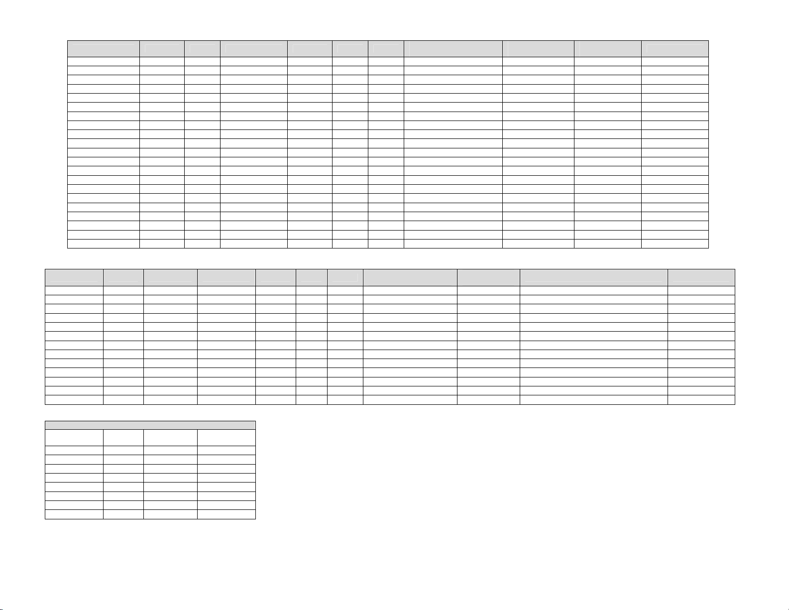
UTILITY SPECIFICATIONS REQUIRED – ELECTRIC
Model Energy Power Voltage Current Phase Hz
1130/60 Electric 10kW 120/208 VAC 48 Amps 1 60 Hz 4 Wires, 2 Pole + N + G 2 Pole, 50 Amp 6 AWG UL, CSA, NSF
1131/61 Electric 10kW 120/240 VAC 42 Amps 1 60 Hz 4 Wires, 2 Pole + N + G 2 Pole, 50 Amp 8 AWG UL, CSA, NSF
1132/62 Electric 10kW 120/208 VAC 28 Amps 3 60 Hz 5 Wires, 3 Pole + N + G 3 Pole, 30 Amp 10 AWG UL, CSA, NSF
1133/63 Electric 10kW 120/240 VAC 25 Amps 3 60 Hz 5 Wires, 3 Pole + N + G 3 Pole, 30 Amp 10 AWG UL, CSA, NSF
1130-080-A Electric 10kW 120/208 VAC 48 Amps 1 60 Hz 4 Wires, 2 Pole + N + G 2 Pole, 50 Amp 6 AWG UL, CSA, NSF
1131/61-080-A Electric 10kW 120/240 VAC 42 Amps 1 60 Hz 4 Wires, 2 Pole + N + G 2 Pole, 50 Amp 8 AWG UL, CSA, NSF
1132/62-080-A Electric 10kW 120/208 VAC 28 Amps 3 60 Hz 5 Wires, 3 Pole + N + G 3 Pole, 30 Amp 10 AWG UL, CSA, NSF
1133-080-A Electric 10kW 120/240 VAC 25 Amps 3 60 Hz 5 Wires, 3 Pole + N + G 3 Pole, 30 Amp 10 AWG UL, CSA, NSF
1134 Electric 10kW 380Y/208 VAC 15 Amps 3 50 Hz 5 Wires, 3 Pole + N + G
1135 Electric 10kW 415Y/240 VAC 14 Amps 3 50 Hz 5 Wires, 3 Pole + N + G
1136 Electric 10kW 240 VAC 42 Amps 1 50 Hz 3 Wires, 1 Pole + N + G
1151 Electric 10kW 200VAC 29 Amps 3 60 Hz 4 Wires, 3 Pole + G
*1164-XXX-E Electric 10kW 400/230 VAC 15 Amps 3 50 Hz 5 Wires, 3 Pole + N + G 3 Pole, 32 Amp
1130-000-A Electric 10kW 208 VAC 48 Amps 1 60 Hz 3 Wires, 2 Pole + G 2 Pole, 50 Amp 6 AWG UL, CSA, NSF
1131-000-A Electric 10kW 240 VAC 42 Amps 1 60 Hz 3 Wires, 2 Pole + G 2 Pole, 50 Amp 8 AWG UL, CSA, NSF
1132-000-A Electric 10kW 208 VAC 28 Amps 3 60 Hz 4 Wires, 3 Pole + G 3 Pole, 30 Amp 10 AWG UL, CSA, NSF
1133-000-A Electric 10kW 240 VAC 25 Amps 3 60 Hz 4 Wires, 3 Pole + G 3 Pole, 30 Amp 10 AWG UL, CSA, NSF
1130-08H-A Electric 12kW 208 VAC 63 Amps 1 60 Hz 3 Wires, 2 Pole + G 2 Pole, 90 Amp 4 AWG UL, cUL, NSF
1131-08H-A Electric 12kW 240 VAC 54 Amps 1 60 Hz 3 Wires, 2 Pole + G 2 Pole, 50 Amp 6 AWG UL, cUL, NSF
1132-08H-A Electric 12kW 208 VAC 36 Amps 3 60 Hz 4 Wires, 3 Pole + G 3 Pole, 70 Amp 8 AWG UL, cUL, NSF
1133-08H-A Electric 12kW 240 VAC 31 Amps 3 60 Hz 4 Wires, 3 Pole + G 3 Pole, 40 Amp 10 AWG UL, cUL, NSF
* REF MODEL NUMBER KEY
Recommended
Electrical Specification
Recommended
Circuit Breaker
Supply Wire
Size 90° C
5 x 2.5mm
5 x 2.5mm
3 x 10.0mm
3 x 4.0mm
5 x 2.5mm
2
2
2
2
2
Agency Listings
NSF
NSF
NSF
NSF
CE, NSF
UTILITY SPECIFICATIONS REQUIRED – GAS
Model Energy Power Voltage Current Phase Hz
1116 Nat. Gas 40,000 BTU 120 VAC 7 Amps 1 60 Hz 3 Wires, 1 Pole + N + G 1 Pole, 15 Amp 40,000 BTU at 7 inches, H2O column** CSA, NSF
1117 L.P. Gas 40,000 BTU 120 VAC 7 Amps 1 60 Hz 3 Wires, 1 Pole + N + G 1 Pole, 15 Amp 40,000 BTU at 11 inches, H2O column** CSA, NSF
1154 Nat. Gas 45 MJ 240 VAC 2 Amps 1 50 Hz 3 Wires, 1 Pole + N + G 45 MJ/HR at 1.7 kPa, H2O column** AGA*, NSF
1155 L.P. Gas 45 MJ 240 VAC 2 Amps 1 50 Hz 3 Wires, 1 Pole + N + G 45 MJ/HR at 2.73 kPa, H2O column** AGA*, NSF
1156 Town 45 MJ 240 VAC 2 Amps 1 50 Hz 3 Wires, 1 Pole + N + G 45 MJ/HR at 3.6 kPa, H2O column** AGA*, NSF
1157 Nat. Gas 40,000 BTU 220/240 VAC 2 Amps 1 50 Hz 3 Wires, 1 Pole + N + G 40,000 BTU at 7 inches, H2O column** NSF
1158 L.P. Gas 40,000 BTU 220/240 VAC 2 Amps 1 50 Hz 3 Wires, 1 Pole + N + G 40,000 BTU at 11 inches, H2O column** NSF
*1154-XXX-E Nat. Gas 12kW 230 VAC 2 Amps 1 50 Hz 3 Wires, 1 Pole + N + G 1 Pole, 16 Amp 12 kW/HR at 17.4 mB, H2O column** CE, NSF
*1155-XXX-E L.P. Gas 12kW 230 VAC 2 Amps 1 50 Hz 3 Wires, 1 Pole + N + G 1 Pole, 16 Amp
1116-000-A Nat. Gas 40,000 BTU 120 VAC 7 Amps 1 60 Hz 3 Wires, 1 Pole + N + G 1 Pole, 15 Amp
1117-000-A L.P. Gas 40,000 BTU 120 VAC 7 Amps 1 60 Hz 3 Wires, 1 Pole + N + G 1 Pole, 15 Amp
1116-080-A Nat. Gas 40,000 BTU 120 VAC 7 Amps 1 60 Hz 3 Wires, 1 Pole + N + G 1 Pole, 15 Amp
1117-080-A L.P. Gas 40,000 BTU 120 VAC 7 Amps 1 60 Hz 3 Wires, 1 Pole + N + G 1 Pole, 15 Amp
Inches of
Water Column
3.5 0.87 8.70 88.9
4.5 1.12 11.2 114.3
7 1.74 17.40 177.8
10 2.48 24.87 254.0
10.5 2.61 26.11 266.7
11 2.73 27.36 279.4
14 3.48 34.81 355.6
14.5 3.61 36.05 368.3
GAS PRESSURE CONVERSION CHART
KPa m-Bar
Millimeters of
Water Column
* AGA – Australia Gas Association (See 1154 & 1155 above)
** NOTE: For proper operation, the gas valve requires a nominal inlet pressure of 7 inches of H
for L.P. gas. A minimum inlet pressure of 1.0 inch of H
must be maintained with no pressure drop from the no load to full load condition. The maximum inlet pressure must be maintained at or below
½ PSIG (14.5 inches H
Electrical Supply for Australia:
Single Phase: 240 VAC, 50 Hz / 20 Amp; one neutral & one earth/ground.
Three Phase: 240/415 VAC / 20 Amp; three active, one neutral & one earth/ground.
All ovens require separate service and dedicated neutral.
NOTE: Do not install the (these) oven(s) in any area with an ambient temperature in excess of 95°F / 35° C. Doing so will cause damage to the
unit.
Recommended
Electrical Specification
O column). Refer to the chart on the left for pressure conversions.
2
Recommended
Circuit Breaker
12 kW/HR at 27.4 mB, H2O column**
40,000 BTU at 7 inches, H2O column**
40,000 BTU at 11 inches, H2O column**
40,000 BTU at 7 inches, H2O column**
40,000 BTU at 11 inches, H2O column**
O column above the manifold setting (NAT. manifold 3.5” H2O, L.P. manifold 10” H2O)
2
Gas Agency Listings
O for natural gas and 11 inches of H2O column
2
CE, NSF
CSA, NSF
CSA, NSF
CSA, NSF
CSA, NSF
4
Impinger II – Digital Advantage Ops Manual –Dom & Int’l

MODEL NUMBER KEY
COUNTRY LANGUAGE CODE NOT USED
1. France French B A
2. Germany German C I
3. Italy Italian D O
4. Spain Spanish E Q
5. United Kingdom English F
6. Luxembourg French B
7. Portugal Portuguese H
8. Denmark Danish J
9. Belgium Dutch / French K
10. Netherlands Dutch L
11. Ireland English F
12. Greece Greek M
13. Austria German C
14. Finland Finnish N
15. Norway Norwegian P
16. Sweden Swedish R
EXAMPLE: 1433-B00-EA
1155- B 00- E A
A = Advantage Style
E = EC Marked Units
00 = Special Unit Designation
(02 = All Stainless Unit)
B = Language
1155 = Main Model Number
NOTE: Date of manufacture is
stamped on the rating plate of each
oven at the end of the serial number.
Example: XXX…01-96
Impinger II – Digital Advantage Ops Manual –Dom & Int’l
5

SPACING
The oven must have 6 inches (152 mm) of clearance from combustible surfaces. In case other equipment is
located on the right side of oven, a minimum clearance of 24 inches (609 mm) is required from that equipment.
FOR ALL OVENS: A 24-inch (609 mm) clearance at the rear of the oven must be obtainable for service access.
FOR IMPINGER® II OVENS: A permanently installed (unmovable) oven requires a minimum of 4 feet clearance on
the right hand side to allow for conveyor removal, cleaning, and servicing.
NOTE: Do not install this (these) oven(s) in any area with an ambient temperature in excess of 95° F / 35° C.
Doing so will cause damage to the unit.
!
CAUTION:
Oven must be operated on approved basis only.
VENTILATION
A VENT IS REQUIRED: Local codes prevail. These are the “authority having jurisdiction” as stated by the
NATIONAL FIRE PROTECTION ASSOCIATION, INC. in NFPA 96 latest edition. In addition, to be in compliance
with the NFPA 54 Section 10.3.5.2, this unit must be installed with a ventilation hood interlock that prevents the unit
from operating when the ventilation hood is off. For further ventilation information, see below.
VENTILATION GUIDELINES
A ventilation hood is required to remove heat and cooking odors. For gas ovens, a ventilation hood is also required
to remove the products of combustion. The hood and HVAC installation must meet local codes to gain approval by
the authority having jurisdiction. Requirements may vary throughout the country depending on the location by city,
county, and state. Obtain information from the authority having jurisdiction to determine the requirements for your
installation. Obtain information and review copies of codes or documents that will be used to inspect and approve
your installation. Your ventilation hood supplier and HVAC contractor should be contacted to provide guidance. A
properly engineered and installed ventilation hood and HVAC system will expedite approval and reduce oven
maintenance costs. Proper ventilation is the oven owner’s responsibility.
The ventilation hood must operate in harmony with the building HVAC system. It typically requires between 750
and 2500 CFM exhaust. (The “Efficiency” of various hood designs makes it necessary to specify such a wide range
of ventilator CFM.) Make up air must be supplied by either a hood design or the HVAC system. This will vary with
hoods from various manufacturers.
CAUTION: Prevent airflow through the cooking tunnel. Air must NOT be directed onto the oven front or at
side of cooking area or rear of oven.
Performance will be evaluated during Start-up Checkout by conducting a smoke candle test. The hood must
capture all smoke from the oven. This is required to assure proper performance of the oven and to eliminate
additional service calls that occur when ambient temperatures are too high. In all cases, the ambient temperature
around the oven must be less than 95° F / 35° C when the oven is operating. In certain localities, other chemical or
gaseous methods of detecting adequate capture will be the requirement to meet the local code authority.
The drawing shown on page 7 is a typical installation and is intended to be a guideline. It is not a rigid
specification. Hood dimensions and the positioning of the hood over the oven will vary with hood manufacturers.
NOTE: Lincoln can provide oven spec sheets that show the dimensions of the oven, KW or BTU ratings and other
information that will be useful to both the ventilation hood supplier and the HVAC contractor.
IN AUSTRALIA: Refer to Standard AS 5601. This standard specifies the requirements for piping, flueing,
ventilation and appliance installation associated with use of or intended use of fuel gases. The requirements of AS
5601 are to be used in conjunction with, but do not take precedence over, any statutory regulations that may apply
in any area.
6
Impinger II – Digital Advantage Ops Manual –Dom & Int’l
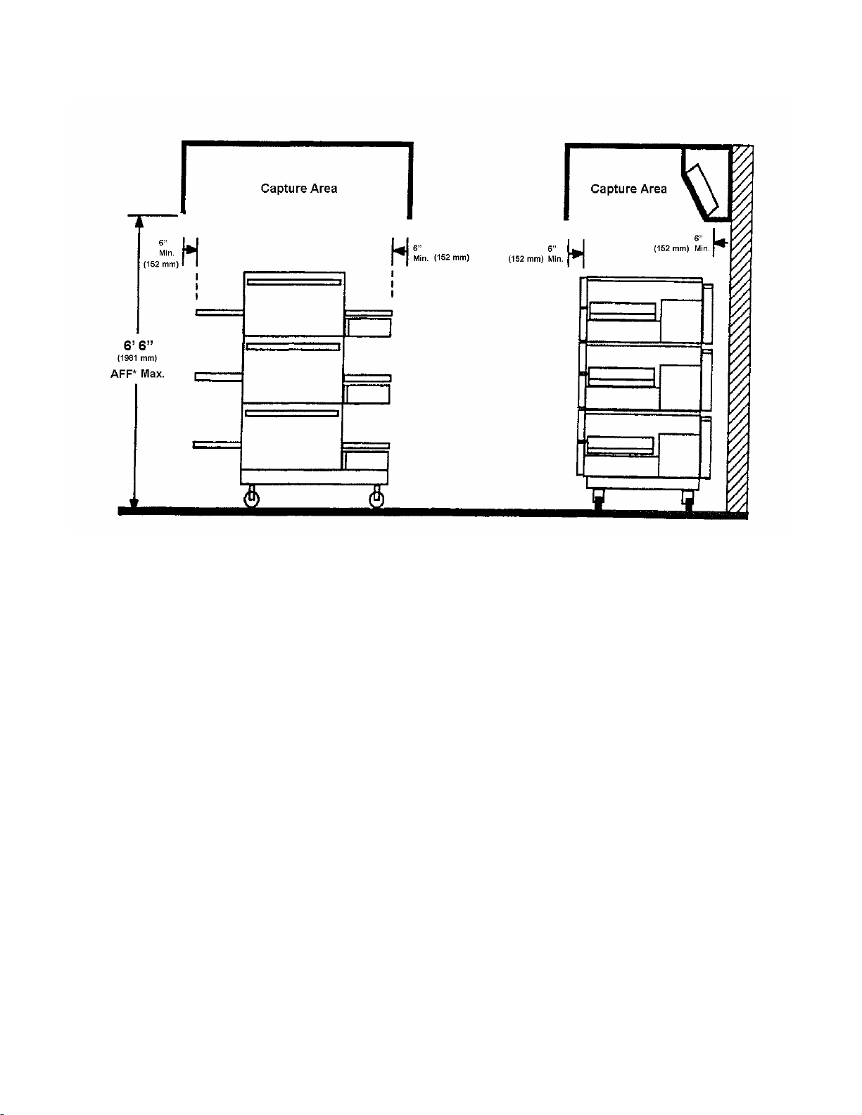
LINCOLN IMPINGER® • 1100 SERIES TRIPLE DECK, DOUBLE DECK
OR SINGLE UNIT CANOPY VENTILATION RECOMMENDATIONS
* AFF = Above Finished Floor
SMOKE CANDLE TEST – VENTILATION SYSTEM VERIFICATION
OVEN SET-UP FOR THIS TEST:
1. This test is to be done on the bottom oven of a multiple oven system, or a single oven.
2. The conveyor must be off.
3. The oven temperature must be set and operating at 550°F/288°C.
TEST PROCEDURE:
Note: Use Lincoln Smoke Candle #369361 (in Australia, an alternate method of coloring the air may be used).
1. Wear heat resistant gloves to prevent burns to your hands.
2. Put the smoke candle in a cake pan approximately 8 inches (200 mm) x 8 inches (200 mm) x 2 inches (50 mm)
deep or equivalent.
3. Open the optional access window in the oven door, the oven door, or insert candle through conveyor opening.
4. Light the fuse of the smoke candle and immediately put the pan and candle into the center of the oven cavity,
on the conveyor belt. (Close the access window or door.)
5. Observe the smoke pattern coming out of the oven openings and the collection of this smoke by the ventilation
system.
6. The ventilation system must capture all the smoke from the oven.
Impinger II – Digital Advantage Ops Manual –Dom & Int’l
7
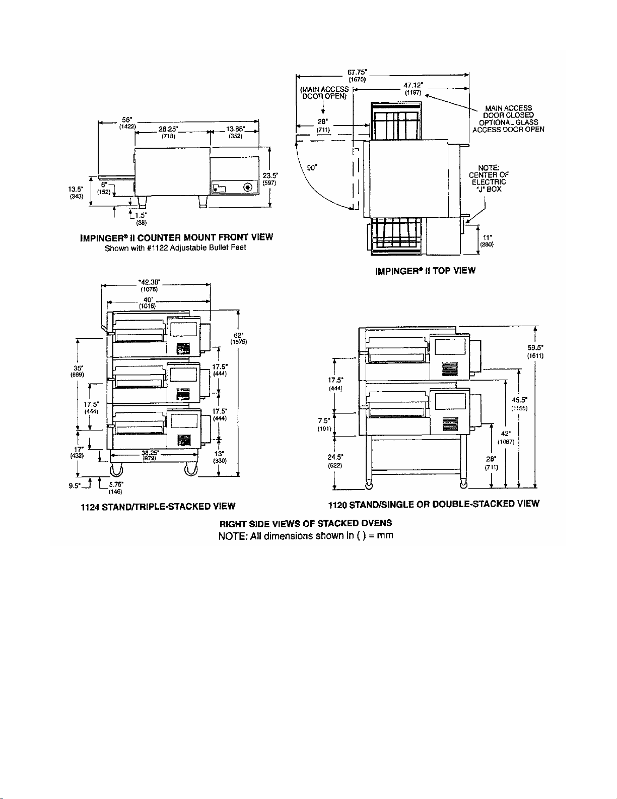
EXTERIOR DIMENSIONS
IMPINGER® II OVEN MODELS
BODY: Stainless steel. Easy open front for simple cleaning.
POWER: Electric, or Gas and Electric
CONVEYOR: Stainless steel construction with flexible stainless steel belt, travel distances of 52 inches
(1320 mm) with 24 inches (610 mm) in the baking area. Conveyor belt width is 18 inches (460
mm). Speed range 50 seconds – 30 minutes.
DB LEVEL: 70dba
OPERATING
TEMPERATURE RANGE: Gas 300° - 550° F (149° - 288° C) Electric 200° - 550° F (93° - 288° C)
NOTE: Specifications are subject to change. Above data should be used for estimating purposes only.
U.S. Patent Nos.: 3,844,213 and 4,154,862; Other Patents Pending.
8
Impinger II – Digital Advantage Ops Manual –Dom & Int’l
 Loading...