

Page 1
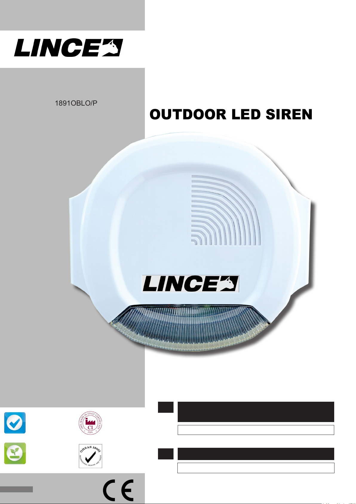
SIRENA LED
AUTOALIMENTATA
LINCE ITALIA S.p.A.
ART. / ITEM:
1827OBLO/L
1880OBLO/A
1891OBLO/P
DA ESTERNO
SELF POWERED
OUTDOOR LED SIREN
La dichiarazione CE del presente articolo
è reperibile sul sito www.lince.net.
The CE declaration of this item is available
on www.lince.net website.
MADE IN ITALY
QUALITY MANAGEMENT
SYSTEM
UNI EN ISO 9001:2008
REG.N.4796
ENVIRONMENTAL
MANAGEMENT
SYSTEM
UNI EN ISO 14001:2004
REG.N.4796-E
CERTIFICATION
100% MADE IN ITALY
IT01.IT/1189.015.V
OCCUPATIONAL
HEALTH
AND SAFETY
MANAGEMENT
SYSTEM
OHSAS 18001:2007
REG.N.4796-I
IT
EN
SIRENA LED AUTOALIMENTATA
DA ESTERNO
Manuale di installazione, uso e manutenzione
SELF POWERED OUTDOOR LED SIREN
Installation, operation and maintenance manual
Page 2

LINCE ITALIA S.p.A.
- Istruzioni originali -
- Translation of the original instructions (original instructions in Italian) -
INDICE
1. INTRODUZIONE ................................................................................................ 3
1.1 CARATTERISTICHE GENERALI ...........................................................3
1.2 CARATTERISTICHE TECNICHE ...........................................................4
1.3 CONTENUTO DELLA CONFEZIONE ....................................................4
1.4 IDENTIFICAZIONE DELLE PARTI ......................................................... 5
1.5 IDENTIFICAZIONE DELLE PARTI DELLA SCHEDA ............................. 6
2. INSTALLAZIONE...............................................................................................7
2.1 MONTAGGIO A MURO ..........................................................................7
2.2 COLLEGAMENTI ELETTRICI ................................................................ 7
2.3 SISTEMA ANTI-FIAMMA ........................................................................7
2.4 SISTEMA ANTI-AVVICINAMENTO ........................................................ 7
2.5 SISTEMA ANTI-PERFORAZIONE ......................................................... 8
2.6 SISTEMA ANTI-SCHIUMA .....................................................................8
2.7 PROGRAMMAZIONE.............................................................................9
2.7.1 Inibizione allarmi ..........................................................................9
2.7.2 Impostazioni uscita BA ................................................................9
2.8 INIZIALIZZAZIONE SIRENA ..................................................................9
2.8.1 FAQ ...........................................................................................10
2.9 ESEMPIO DI COLLEGAMENTO ..........................................................10
3. LOGICA DI FUNZIONAMENTO ..................................................................... 11
3.1 LED DI ALLARME ................................................................................ 11
3.2 LED DI STATO ..................................................................................... 11
4. MANUTENZIONE E VERIFICHE PERIODICHE ............................................. 11
4.1 SOSTITUZIONE PERIODICA DELLA BATERIA .................................. 11
5. SMALTIMENTO E ROTTAMAZIONE .............................................................. 11
5.1 DISINSTALLAZIONE ............................................................................ 11
CONTENTS
1. DESCRIPTION .................................................................................................. 3
1.1 GENERAL FEATURES .......................................................................... 3
1.2 TECHNICAL FEATURES ....................................................................... 4
1.3 PACKAGING CONTENTS ......................................................................4
1.4 PARTS IDENTIFICATION.......................................................................5
1.5 BOARD PARTS IDENTIFICATION ......................................................... 6
2. INSTALLATION ................................................................................................. 7
2.1 WALL MOUNTING .................................................................................7
2.2 ELECTRICAL WIRING ........................................................................... 7
2.3 FLAME-PROOF SYSTEM ......................................................................7
2.4 ANTI-APPROACHING SYSTEM ............................................................7
2.5 ANTI-PERFORATION SYSTEM .............................................................8
2.6 ANTI-FOAM SYSTEM ............................................................................ 8
2.7 ALARM LED SIGNALLING MEANING ................................................... 9
2.7.1 Alarm inhibition ............................................................................ 9
2.7.2 BA otuput settings .......................................................................9
2.8 SIREN INIZIALIZATION .........................................................................9
2.8.1 FAQ ...........................................................................................10
2.9 EXAMPLE OF CONNECTION ............................................................. 10
3. LED SIGNALLING MEANING ......................................................................... 11
3.1 ALARM LED ......................................................................................... 11
3.2 STATUS LED ........................................................................................ 11
4. MAINTENANCE AND PERIODIC CHECKS ................................................... 11
4.1 PERIODIC REPLACEMENT OF THE BATTERY ................................. 11
5. DISPOSAL AND SCRAPPING ........................................................................ 11
5.1 DISMANTLING ..................................................................................... 11
Le informazioni riportate in questo manuale sono state compilate
con cura, tuttavia LINCE ITALIA S.p.A. non può essere ritenuta
responsabile per eventuali errori e/o omissioni. LINCE ITALIA
S.p.A. si riserva il diritto di apportare in ogni momento e senza
preavviso, miglioramenti e/o modiche ai prodotti descritti
nel presente manuale. Consultare il sito www.lince.net per le
condizioni di assistenza e garanzia. LINCE ITALIA S.p.A. pone
particolare attenzione al rispetto dell’ambiente. Tutti i prodotti ed i
processi produttivi sono progettati con criteri di eco-compatibilità.
Il presente articolo è stato prodotto in Italia.
The information in this manual has been issued with care, but
LINCE ITALIA S.p.A. will not be responsible for any errors or
omissions. LINCE ITALIA S.p.A. reserves the right to improve
or modify the products described in this manual at any time
and without advance notice. Terms and conditions regarding
assistance and the product warranty can be found at LINCE
ITALIA’s website www.lince.net. LINCE ITALIA S.p.A. makes it a
priority to respect the environment. All products and production
processes are designed to be eco-friendly and sustainable.
This product has been Made in Italy
2
Page 3

LINCE ITALIA S.p.A.
1. INTRODUZIONE
Il manuale descrive le modalità di installazione delle sirene
autoalimentate serie OBLÒ. La sirena è il principale dispositivo
di segnalazione a cui deve essere dato un alto grado di sicurezza
e di afdabilità nel tempo. Le sirene sono conformi alla normativa
CEI EN50131-4 Grado 3 , Classe Ambientale IV. L’apertura del
coperchio e lo strappo dal muro sono protetti dalla presenza di
un microswitch mentre il funzionamento a sicurezza intrinseca
(allarme per mancanza di positivo o di negativo) protegge contro
il taglio dei cavi. La sirena dispone di un contatto normalmente
chiuso (NC) per il collegamento con la linea antisabotaggio delle
centrali antifurto.
1.1 CARATTERISTICHE GENERALI
• Contenitore in policarbonato.
• Selezione tono sirena.
• Flash LED per segnalazione ottica.
• LED per segnalazione stato impianto.
• Protezione contro taglio li.
• Protezione contro la rimozione del coperchio.
• Protezione contro lo strappo dal muro.
• Durata limitata della segnalazione acustica.
• Controllo batteria ogni 5 minuti.
• Controllo speaker.
• Circuito antisabotaggio incorporato.
• Scheda elettronica tropicalizzata.
• Esistenza in vita (1 lampeggio ogni minuto).
• Alloggiamento per batteria da 12 V 2,2 Ah (batteria non
inclusa).
• Antiamma.
• Antiavvicinamento (solo 1880OBLO/A e 1891OBLO/P).
• Antiperforazione (solo 1891OBLO/P).
• Antischiuma.
1. DESCRIPTION
The manual describes how to install the OBLÒ series selfpowered LED sirens. The siren is the main warning device to
which it must be given a high degree of safety and reliability over
time. The OBLÒ serie sirens have been designed compliant to
the standard CEI EN50131-4 Grade 3, Environmental Class IV.
Opening the lid and removal from the wall are protected by a
micro switch, while intrinsically safe operation (alarm for lack of
positive or negative) protects against the wire-cutting. The siren
has a normally closed contact (NC) to connect to the tamper
alarm.
1.1 GENERAL FEATURES
• Polycarbonate casing.
• Tone selection.
• Flashlight module in LED technology.
• LED for system status signalling.
• Protection against wire-cutting.
• Lid tamper.
• Protection against removal from the wall.
• Limited acoustic alarm.
• Battery test every 5 minutes.
• Speaker test.
• Protection tamper circuit.
• Conformal coating on electronic board.
• Work signalling LED (1 ash per minute).
• Housing for battery 12 V 2,2 Ah (battery not included).
• Flameproof.
• Anti-approaching (1880OBLO/A and 1891OBLO/P only).
• Anti-perforation (1891OBLO/P only).
• Anti-foam.
3
Page 4
LINCE ITALIA S.p.A.
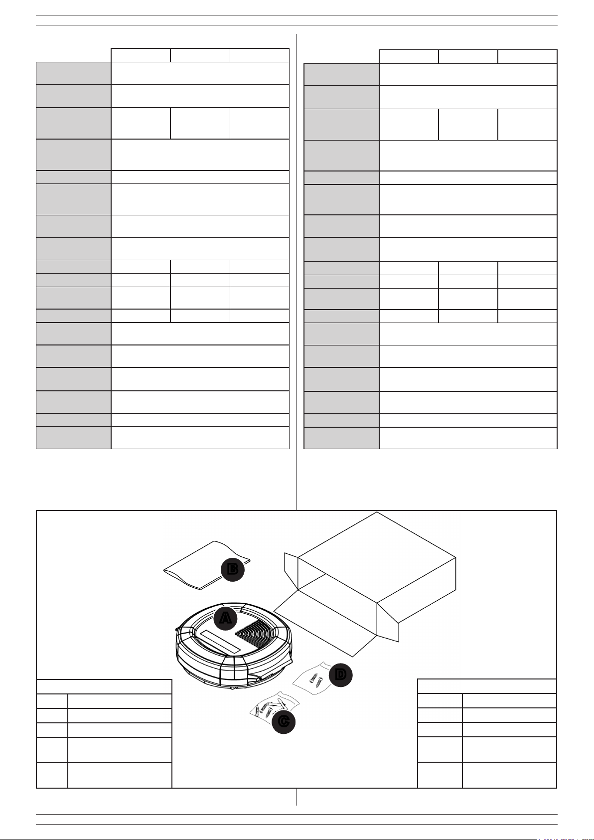
1.2 CARATTERISTICHE TECNICHE
1827OBLO/L 1880OBLO/A 1891OBLO/P
Alimentazione
(min-max)
Frequenza
fondamentale
Assorbimento a
riposo da centrale
(batteria carica)
Assorbimento
massimo in
allarme
Pressione sonora >103 dB @ 3 m
Corrente massima
di ricarica della
batteria
Tensione massima
della batteria
Durata batteria
stimata
Antiamma SI SI SI
Anti-schiuma SI SI SI
Anti-
avvicinamento
Anti-perforazione NO NO SI
Grado di
protezione
Tempo massimo di
allarme
Tempo di
installazione
Temperatura di
funzionamento
Dimensioni 277 x 251 x 72 mm
Peso della
confezione
55 mA 65 mA 67 mA
NO SI SI
11 ÷ 15 Vcc.
1800 Hz
1 A
200 mA
14 V
60 cicli di allarme
IP43
5 minuti
1 minuto
-25 ÷ +60 °C
1,4 Kg (senza batteria)
1.2 TECHNICAL FEATURES
1827OBLO/L 1880OBLO/A 1891OBLO/P
Operating voltage
(min-max)
Operating
frequency
Consumption
at rest (charged
battery)
Maximum alarm
consumption
SPL >103 dB @ 3 m
Maximum charge
current battery
Maximum battery
voltage
Battery life 60 alarm cycles
Flameproof YES YES YES
Anti-foam YES YES YES
Anti-approaching NO YES YES
Anti-perforation NO NO YES
Enclosure degree
of protection
Sound time-out 5 minutes
Installation time 1 minute
Operating
temperature
Dimensions 277 x 251 x 72 mm
Package weight 1,4 Kg (without battery)
55 mA 65 mA 67 mA
11 ÷ 15 Vcc.
1800 Hz
1 A
200 mA
14 V
IP43
-25 ÷ +60 °C
1.3 CONTENUTO DELLA CONFEZIONE
A
Tabella 1
Part. Identicazione
A Sirena
B Manuale di istruzioni.
Kit di ssaggio al muro
C
(all’interno della sirena).
Viti di chiusura sotto-
D
coperchio
Fig. 1
B
1.3 PACKAGING CONTENTS
D
C
Table 1
Ref. Identication
A Siren.
B Istruction manual.
Kit for wall mounting
C
(inside the siren).
Screws for under-lid
D
closing
4
Page 5
LINCE ITALIA S.p.A.
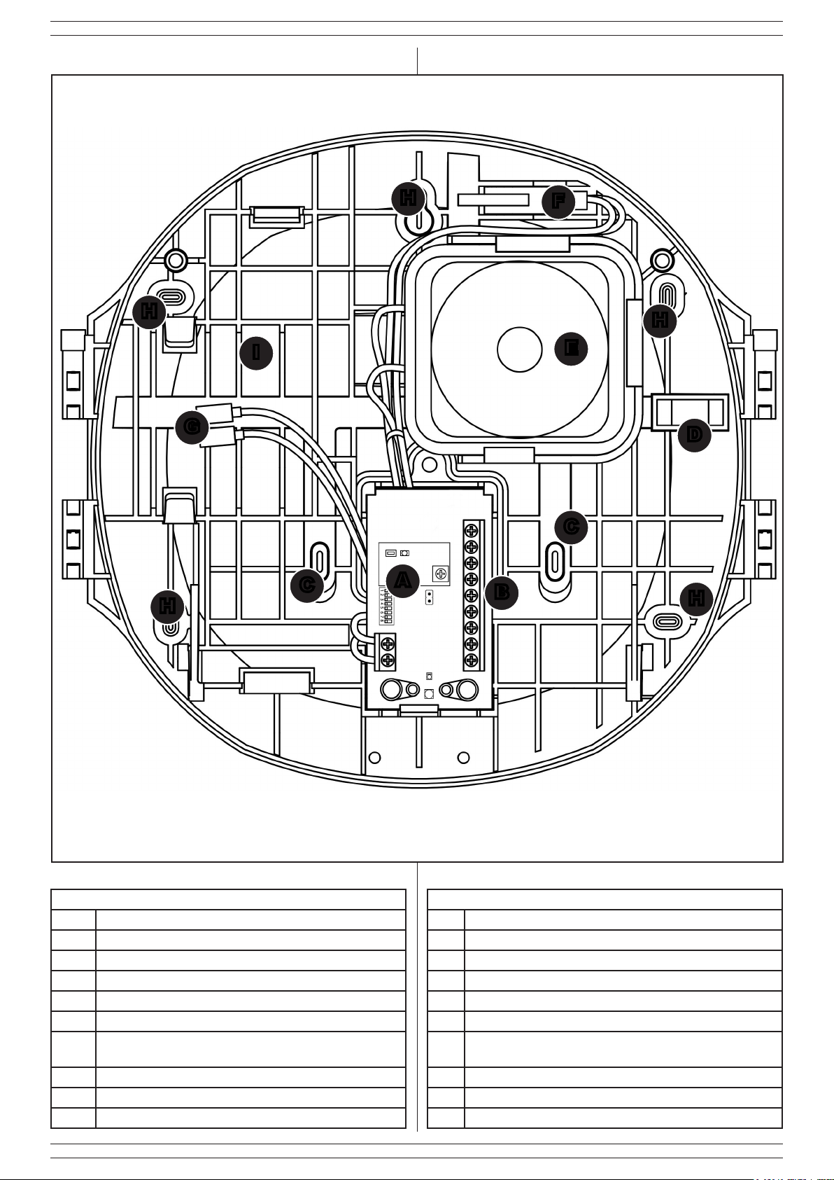
1.4 IDENTIFICAZIONE DELLE PARTI
H
I
G
1.4 PARTS IDENTIFICATION
H
F
E
H
D
H
Fig. 2
Tabella 2
Part. Identicazione
A Scheda elettronica
B Morsettiera
C Passaggio cavi
D Livella
E Altoparlante
Microswitch antisabotaggio e foro antistrappo (sotto il
F
microswitch)
G Faston per il collegamento della batteria
H Fori di ssaggio al muro
I Vano per batteria al piombo da 2,2 Ah
C
C
A
B
Ref. Identication
A Electronic board
B Terminal block
C Wire passage
D Tubolar vial
E Speaker
Tamper and wall tamper microswitch and wall tmaper
F
hole (under the microswitch)
G Fastons for battery connection
H Wall xing slots
I Seat for 2,2 Ah lead battery
H
Table 2
5
Page 6
LINCE ITALIA S.p.A.
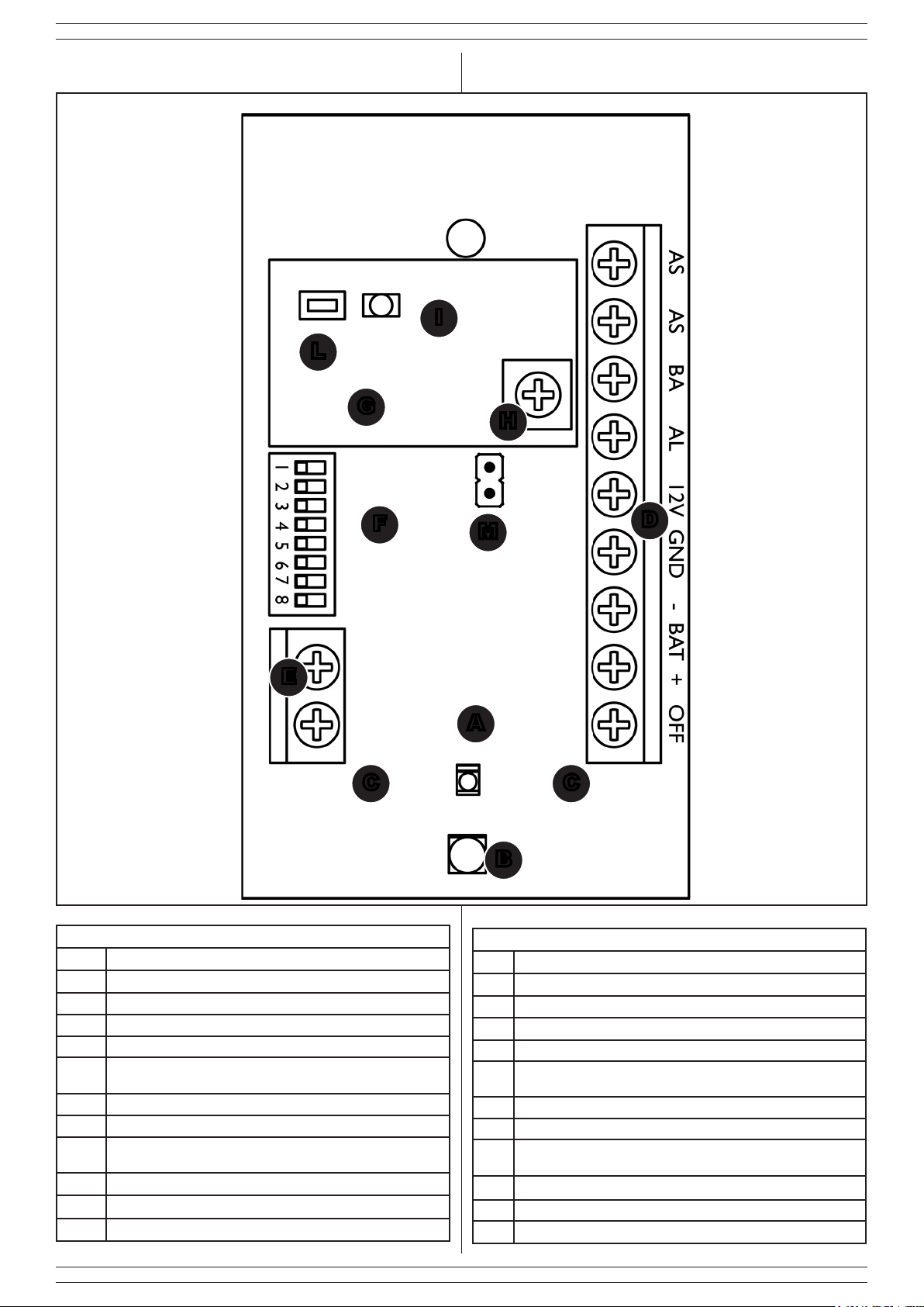
1.5 IDENTIFICAZIONE DELLE PARTI DELLA
SCHEDA
I
L
G
1.5 BOARD PART IDENTIFICATION
H
F
E
Fig. 3
Tabella 3
Part. Identicazione
A LED rosso di stato impianto rosso
B LED di allarme blu
C Barriere IR antiavvicinamento
D Morsettiera per collegamenti
Morsettiera per il collegamento dell’altoparlante (già collega-
E
to)
F Dip-Switch
G Scheda antiperforazione (solo su 1891OBLO/P)
Trimmer per la regolazione della sensibilità antiperforazione
H
(solo su 1891OBLO/P)
I LED perforazione in corso (solo su 1891OBLO/P)
L Tasto reset allarme antiperforazione (solo su 1891OBLO/P)
M Jumper per segnalazioni su morsetto BA (Grado 3)
M
D
A
CC
B
Table 3
Ref. Identication
A System status red LED
B Blue Alarm LED
C Anti-approaching IR barriers
D Terminal block for connections
E Terminal block for loudspeaker (connected in factory)
F Dip-Switch
G Anti-perforation board (1891OBLO/P only)
Trimmer for anti-perforation sensibility setting (1891OBLO/P
H
only)
I LED perforation in progress (1891OBLO/P only).
L Anti-perforation alarm reset button (1891OBLO/P only).
M Jumper for signalings on BA terminal block (Grade 3)
6
Page 7

LINCE ITALIA S.p.A.
2. INSTALLAZIONE
2.1 MONTAGGIO A MURO
Per l’installazione a muro procedere nel modo seguente:
• rimuovere una delle due viti di chisura presenti al lato della
sirena;
• aprire il coperchio;
• aprire il sottocoperchio;
• con un utensile rimuovere le parti in plastica per il passaggio
dei cavi
• far passare i cavi di collegamento attraverso l’apposita
apertura dopo aver sfondato il tassello pretagliato (C-Fig.2);
• ssare il supporto a muro utilizzando i 5 fori (H-Fig.2) e
metterla in piano utilizzando la livella (D-Fig.2);
• con un opportuno utensile, rimuovere il microswitch
antisabotaggio F-Fig.2 per il ssaggio del foro antistrappo;
• riposizionare il microswitch antistrappo F-Fig.2 nella propria
sede;
• effettuare i collegamenti elettrici come descritti nel paragrafo
relativo e nell’esempio del paragrafo 2.9;
• chiudere il sottocoperchio utilizzando le viti in dotazione;
• chiudere il coperchio avvitando la vite (imperdibile) svitata
in precedenza.
2. INSTALLATION
2.1 WALL MOUNTING
For wall mounting, proceed as following:
• Remove one of the two screws placed on each side of the
siren;
• open the lid:
• open the under-lid;
• remove the plastic parts of wire passage with a tool;
• route the cables through the passages (C-Fig.2);
• mount the backplate using the 5 slots (H-Fig.2) and place it
vertically by using the tubolar vial (D-Fig.2);
• wth an appropriate toool, remove the miscroswitch F-Fig.2
and x the mounting hole to activate the wall tamper function;
• place again the microswitch F-Fig.2 in its position.
• wiring as described in the next paragraph and in the example
in paragraph 2.9;
• close the under-lid using the supplied screws;
• close the lid by screwing the screw removed previously.
2.2 COLLEGAMENTI ELETTRICI
• +BAT-: su questi morsetti collegare la batteria (non in
dotazione) rispettando la polarità.
• GND: negativo di alimentazione.
• 12V: positivo di alimentazione.
• AL: morsetto da collegare con un’uscita della centrale (la
sirena entra in funzione per una mancanza di positivo o di
negativo secondo settaggio DIP1, vedere programmazione
sirena paragrafo 2.3).
• BA: collegare l’uscita ad un ingresso centrale in grado di
gestire un segnale negativo presente o negativo assente
modo NA o modo NC secondo la programmazione del DIP
2 (collegare al morsetto BA delle centrali LINCE).
• AS AS: morsetti collegati al microinterruttore antisabotaggio
che si apre quando si rimuove il coperchio frontale della
sirena. Collegare questi morsetti alla linea antisabotaggio di
una centrale di allarme o zona programmata 24h.
• OFF: collegare questo morsetto se si desidera avere la
visualizzazione dello stato dell’impianto sul LED rosso; per
la sua programmazione fare riferimento a quanto riportato al
paragrafo 2.7 relativamente alla programmazione del DIP 5.
2.3 SISTEMA ANTI-FIAMMA
Il sistema anti-amma permette di proteggere la sirena dai
tentativi di effrazione effettuati, ad esempio, con una torcia a gas.
2.2 ELECTRICAL WIRING
• + BAT-: battery terminal blocks (battery not included)
matching the polarity.
• GND: negative power supply.
• 12V: positive power supply.
• AL: terminal to be connected with an output of the control
panel (the siren works for a lack of positive or negative as
set by DIP1, see programming paragraph 2.3).
• BA: connect the output to an input type NA or NC able
to manage a lack of negative or presence of negative,
according to DIP 2 settings (connect to the LINCE’s control
panel terminal BA).
• AS AS: terminals connected to the tamper microswitch
which opens when the lid is removed. Connect these
terminals to the control panel tamper alarm or an input
programmed as tamper 24h;
• OFF: use this terminal if you want to see the system satus
on the system status red LED; for its setting, please refer to
paragraph 2.7 relatively to the programming of the DIP 5.
2.3 FLAME-PROOF SYSTEM
The ame-proof system allows to protect against burglary
attempts carried out, for instance, with a gas torch.
2.4 SISTEMA ANTI-AVVICINAMENTO
Il sistema anti-avvicinamento previene qualsiasi tentativo di
avvicinamento alla sirena; la distanza di rilevamento massima
è di 30 cm.
Nel caso di avvicinamento alla sirena si avrà un lampeggio
ogni 0,5 secondi per circa 2÷3 secondi al termine dei quali,
la sirena aprirà la linea 24h segnalando in questo modo il
tentativo di effrazione; in caso di malfunzionamento del sistema
antiavvicinamento si avrà un lampeggio del LED di allarme ogni
secondo.
2.4 ANTI-APPROACHING SYSTEM
The anti-approaching system prevents every attempts of getting
closer to the siren; the maximum detecting distance is 30 cm.
If both IR beams are reected it will have a ashing of the alarm
LED every 0,5 seconds for about 2÷3 seconds after witch, the
siren will open the 24h line for signaling the effraction attempt;
in case of failure of the anti-approaching system you will have a
LED alarm ashing every second.
7
Page 8
LINCE ITALIA S.p.A.
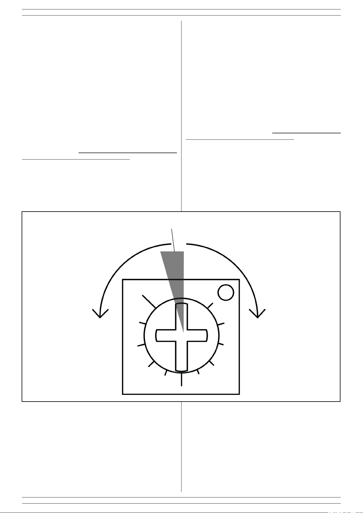
2.5 SISTEMA ANTI-PERFORAZIONE
Il sistema anti-perforazione è costituito da un accelerometro
con sensibilità regolabile. La scheda G permette di rilevare un
tentativo di perforazione della sirena effettuato secondo quanto
riportato nella EN50131-4. Il dispositivo è dotato di un trimmer H
che permette la regolazione della soglia di rilevamento (g. 3).
Ruotare il trimmer in senso orario per aumentare la sensibilità
del sensore: all’aumento della sensibilità il LED I lampeggerà più
velocemente solo nella fase di installazione.
Al ne di ottenere una rilevazione ottimale, portare il trimmer
a metà della corsa, tenendo presente che la zona a sinistra è
consigliabile per rilevazioni in ambienti difcili, mentre a destra
per rilevazioni in ambienti normali; fare riferimento alla gura 4
successiva per ultriori dettagli.
Dopo la fase di installazione, ogni volta che la scheda rileverà
un superamento della soglia impostata accenderà brevemente
il LED rosso I. Il rilevamento di un certo numero di impulsi in un
breve arco di tempo porterà la scheda ad aprire la linea 24h della
sirena per 30 secondi. Ruotando totalmente il trimmer in senso
antiorario è possible escludere la rilevazione.
NOTE:
• La funzione anti-perforazione è disabilitata di default;
• evitare, per quanto possibile, l'installazione su tramezzi o
più in generale su zone soggette a forti vibrazioni favorendo
quindi l'installazione su muri portanti e zone non soggette a
forti vibrazioni.
2.5 ANTI-PERFORATION SYSTEM
The anti-perforation system consists of an accelerometer with
adjustable sensibility. The board G allows to detect a drilling
attempt to the siren according to EN50131-4. The device is
equipped with the trimmer H that allows to set the detection
threshold (g. 3). Turn the trimmer clockwise to increase the
sensibility of the sensor: the more the sensibility is increased,
the LED I ashes faster.
In order to get an optimal detection, turn the trimmer to half
of its run, keeping in mind that the part on the left is advisable
for detection in hostile scenery, while on the right is advisable
for normal scenery; please refer to g. 4 for further informations.
After the installation step, every time that the board detects a
threshold exceeded will turn on the red LED I. The detection
of a number of pulses in a short time range will open the 24h
line of the siren for 30 seconds.Totally turning the trimmer
counterclockwise you can exclude detection.
NOTE:
• the anti-perforation function is disabled for deafult;
• avoid, as far as possible, the installation on parition wall or in
general on place subject to strong vibrations promoting the
installation on load-bearing wall and place not subjected to
strong vibrations
AMBIENTI DIFFICILI
• aeroporti e zone limitrofe;
• stazioni ferroviare e zone limitrofe;
• zone soggette a forti vibrazioni.
HOSTILE PLACES
• airports and surrounding areas;
• railway stations and surrounding
areas;
• areas subject to strong vibration.
ZONA OTTIMALE DI RILEVAZIONE
OPTIMAL DETECTION ZONE
AMBIENTI OTTIMALI
• zone fuori città;
• zone non soggette a forti vibrazioni
OPTIMAL PLACES
• areas outside the city;
• areas not subject to strong
vibrations
Fig. 4
2.6 SISTEMA ANTI-SCHIUMA
Il sistema antischiuma è costituito da due fasci IR. Quando
vengono interrotti entrambi, viene aperta la linea 24h della
sirena; nel caso in cui ne venga interrotto uno solo, ad esempio
per un insetto o un’ostruzione presente sulla scheda, il LED
di allarme lampeggerà per 12 volte consecutive. La sirena
controlla periodicamente la presenza di ostacoli (schiuma)
8
2.6 ANTI-FOAM SYSTEM
The anti-foam system consist of two IR beam placed in the upper
side of the board. When both beams are interrupted, the 24h
line is opened; if only one beam is interrupted, for instance the
presence on the board of a bug of another kind of obstruction,
the alarm LED will ash consecutively for 12 times. The siren
periodically checks the presence of an obstacle (foam).
Page 9
LINCE ITALIA S.p.A.
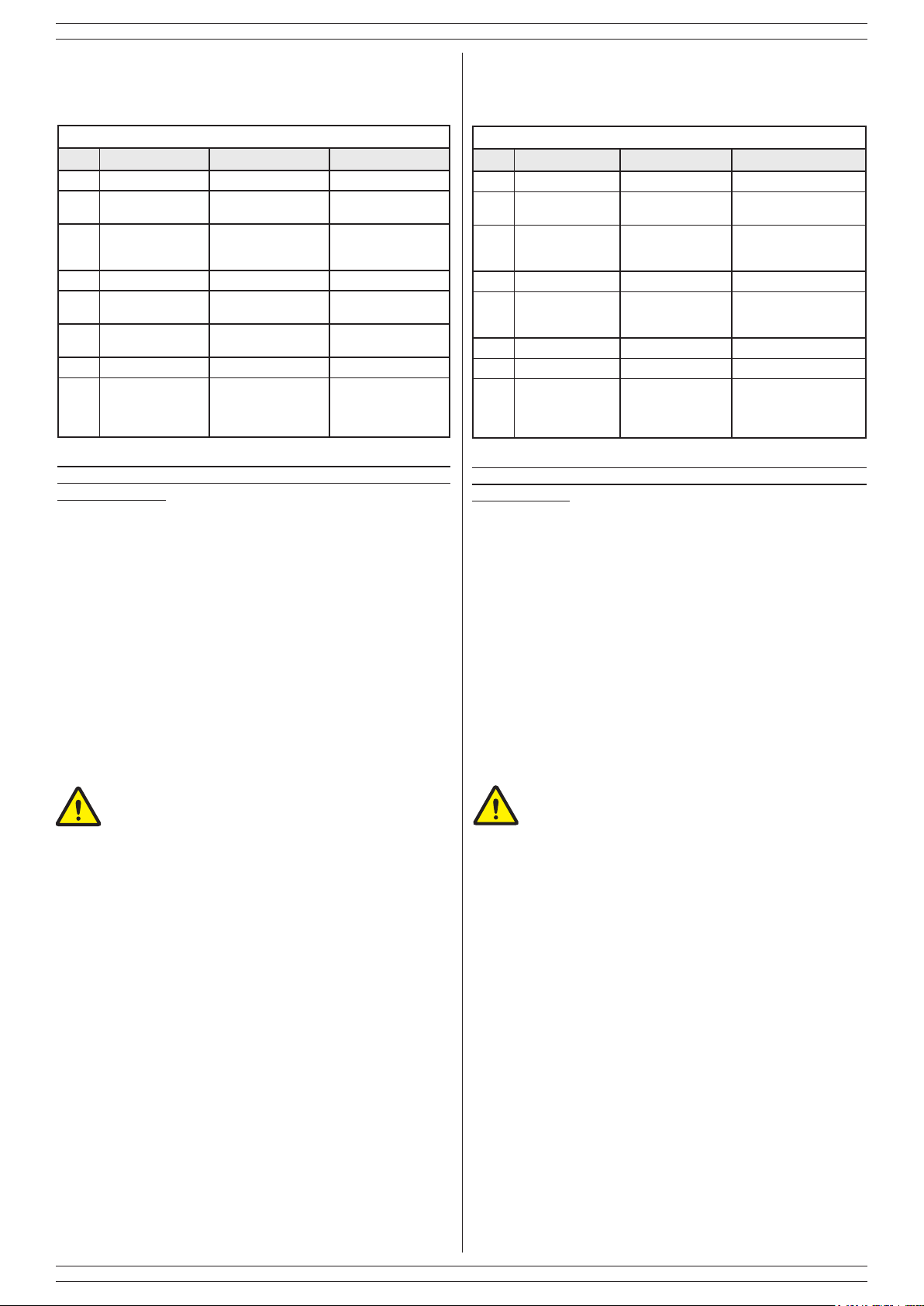
2.7 PROGRAMMAZIONE
Le impostazioni della sirena sono effettuabili variando la
posizione dei DIP-SWITCH (in grassetto il default).
Tabella 4
DIP Descrizione OFF ON
1 Partenza allarme Mancanza di positivo Mancanza di negativo
Selezione controllo
2
batteria scarica
Temporizzazione
3
antisabotaggio
4 Tono sirena Suono lento Suono veloce.
5 Stato impianto
Segnalazione esi-
6
stenza in vita
7 Inibizione allarmi Non attiva Attiva
Antiamma, antiavvicinamento, anti-
8
schiuma, antiperforazione
Se si modicano le impostazioni con la sirena alimentata è
necessario disalimentare e rialimentarla stessa afnchè le stess
diventino effettive
Negativo presente a
batteria scarica
Attivazione dipen-
dente da centrale.
LED accesso all’ arrivo del negativo
Non attiva Attiva
Non attive Attive
Negativo a mancare a
batteria scarica
Attivazione indipendente da centrale (30
s.)
LED accesso all’ arrivo del positivo.
2.7 PROGRAMMING
The programs of the siren can be changed by varying the position
of the DIP-switches (default is in bold).
Table 4
DIP Description OFF ON
1 Start alarm Lack of a positive Lack of a negative .
Selection battery
2
check
3 Lid tamper
4 Sound modes Slow sound. Fast sound.
5 System status
6 Work signalling Not Active Active.
7 Alarm inibition Not active Active
Flameproof, antiapproaching,anti-
8
foam, antiperforation
If the settings have been modied with the siren powered on, it is
necessary to power off and power on the siren again for actualize
the modication
Presence of negative with low battery
Lid tamper depen-
dent of the control
panel.
LED power on with
presence of negati-
ve signal
Not active Active
Absence of negative with
low battery
Lid tamper independent
of the control panel. (30
s.)
LED power on with presence of positive signal
2.7.1 Inibizione allarmi
Se attiva, dopo 5 allarmi consecutivi all’interno di una
stessa attivazione dell’impianto, il LED rosso di stato inizia a
lampeggiare e la sirena rimarrà inibita. Per ripristinare il normale
funzionamento è necessario effettuare una variazione di stato
2.7.2 impostazioni uscita BA
Il Jumper M (Fig. 3) permette di inviare in centrale (tramite
morsetto BA) diverse informazioni a seconda del proprio stato:
• Aperto (default): Stato batteria (scarica o guasta);
• Chiuso: Stato battera, stato alimentazione esterna, integrità
cavo allarme
Per avere la sirena compatibile con il grado 3, è
necessario chiudere il jumper e disporre di una centrale
in grado di interpretare opportunamente il cambiamento
di stato del morsetto BA.
2.8 INIZIALIZZAZIONE SIRENA
In fase di installazione il comportamento è il seguente:
• appena si alimenta la sirena, da batteria o da centrale, il
lampeggiatore si attiva emettendo un lampeggio ogni 4
secondi (lampeggio lento);
• quando viene effettuata l’ultima operazione, ovvero la
chiusura del microswitch AS, se tutto è ben collegato, il
lampeggio diventerà veloce, un lampeggio ogni 1,5 secondi;
• dopo un minuto di lampeggio veloce, il ash si spegne e la
sirena è pronta per funzionare.
Al termine del lampeggio veloce, per 3 minuti è possibile
effettuare prove di rilevazione della funzione antiavvicinamento.
In caso di rilevazione la sirena non genera allarme ma visualizza
il funzionamento tramite LED rosso che lampeggia avvicinandosi
e diventa sso in caso di rilevazione.
Se c’è un problema, (es.: non si è data alimentazione esterna,
antisabotaggio aperto, batteria guasta o non collegata, speaker
rotto) alla chiusura del coperchio il lampeggio continuerà ad
essere lento per indicare che c’è un’anomalia, il lampeggio
diventa veloce solo quando tutto è funzionante.
2.7.1 Alarm inhibition
If active, after 5 consecutive alarm within a single system
activation, the red status LED starts to ash and the siren will
be inhibited. To restore normal operation, you should make a
change in status, and connect the OFF terminal block
2.7.2 BA output settings
The Jumper M (g. 3) allows to send to the control panel (through
BA terminal block) several infromation depending on its status:
• Open (default): Battery status (low or failure);
• Closed: batterys status, external power supply status,
alarm cable integrity,
To have a grade 3 compliant siren, it is necessary to
close the jumper and to have a central able to properly
interpret the change of state of the BA terminal block.
2.8 SIREN INIZIALIZATION
During installation, the behavior is the following:
• power the siren by battery or control panel and the ashlight
is activated emitting a ash every 4 seconds (slow);
• after the last operation, i.e. closure of the microswitch AS, if
everything is OK, ashing becomes faster, one ash every
1.5 seconds;
• after one minute the ash goes off and the siren is ready to
work.
At the end of the fast ashing, for 3 minutes it is possible to
perform detection tests of anti-approaching system. When
it detects the siren does not generate allarm but displays the
operation via red LED that ashes if approaching and becomes
xed in case of detection.
If there is an issue (e.g. no control panel power supply, tamper
contact open, battery failure or not connected, broken speaker) at
the end the ashlight module will continue to be slow, indicating
a fault; the ashing becomes faster only when everything is
working.
9
Page 10
LINCE ITALIA S.p.A.
NOTA:
Per completare la fase di installazione non è necessario
collegare i morsetti BA e AS. In caso di inversione di polarità della
batteria la fase di installazione non viene completata, mentre se
l’inversione avviene dopo l’installazione il LED segnalerà sia la
batteria guasta sia la mancanza di alimentazione.
2.8.1 FAQ
Se l’installazione non va a buon ne, vericare i seguenti punti:
1. collegamento dell’altoparlante;
2. batteria tampone carica;
3. alimentazione da centrale maggiore di 11 V;
4. microswitch antitamper correttamente collegato;
5. microswitch antitamper correttamente chiuso;
6. barriere IR antischiuma libere.
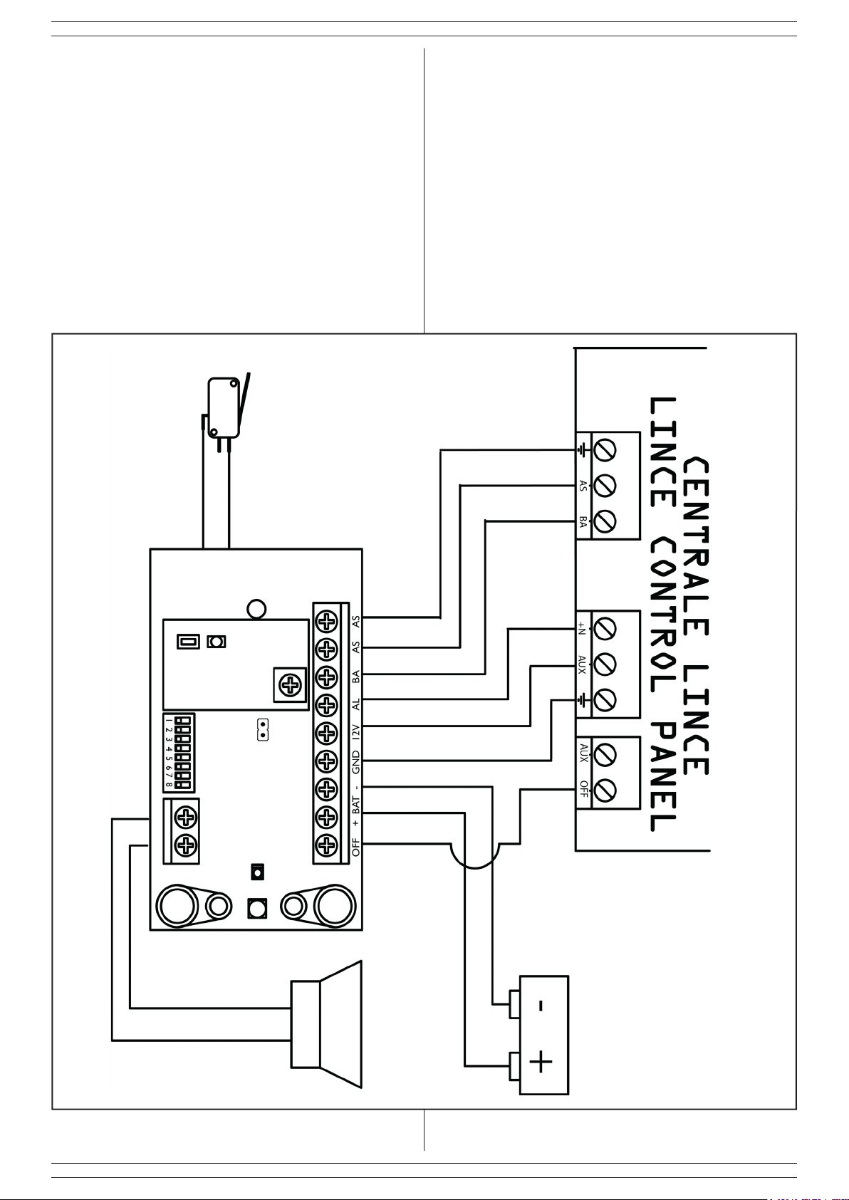
2.9 ESEMPIO DI COLLEGAMENTO
NOTE:
To complete the installation is not necessary to connect the
terminals BA and AS to the control panel. In case of reverse
polarity of the battery, the installation is not successfully
completed, while if it occurs after installation, the LED lights both
the battery faulty and the operating voltage lacking.
2.8.1 FAQ
If the installation is unsuccessful, check the following:
1. speaker connected
2. backup battery charged;
3. power supply form the control panel greater than 11 V;
4. antitamper microswitch correctly connected;
5. antitamper microswitch correctly close;
6. free anti-foam IR beams.
2.9 EXAMPLE OF CONNECTION
Fig. 5
L’esempio si riferisce alle programmazioni di fabbrica.
10
The example refers to the default programming ground.
Page 11
LINCE ITALIA S.p.A.
NOTE:
in caso di mancanza di collegamenti disponibili dalla centrale, il
morsetto AL può essere ponticellato o verso 12 V o verso GND
(in base alla programmazione del DIP1) e collegato in centrale
sul morsetto del comando dedicato alla sirena esterna o a uno
scambio libero relè. Questo tipo di collegamento potrebbe,
però, compromettere la durata della batteria nel tempo.
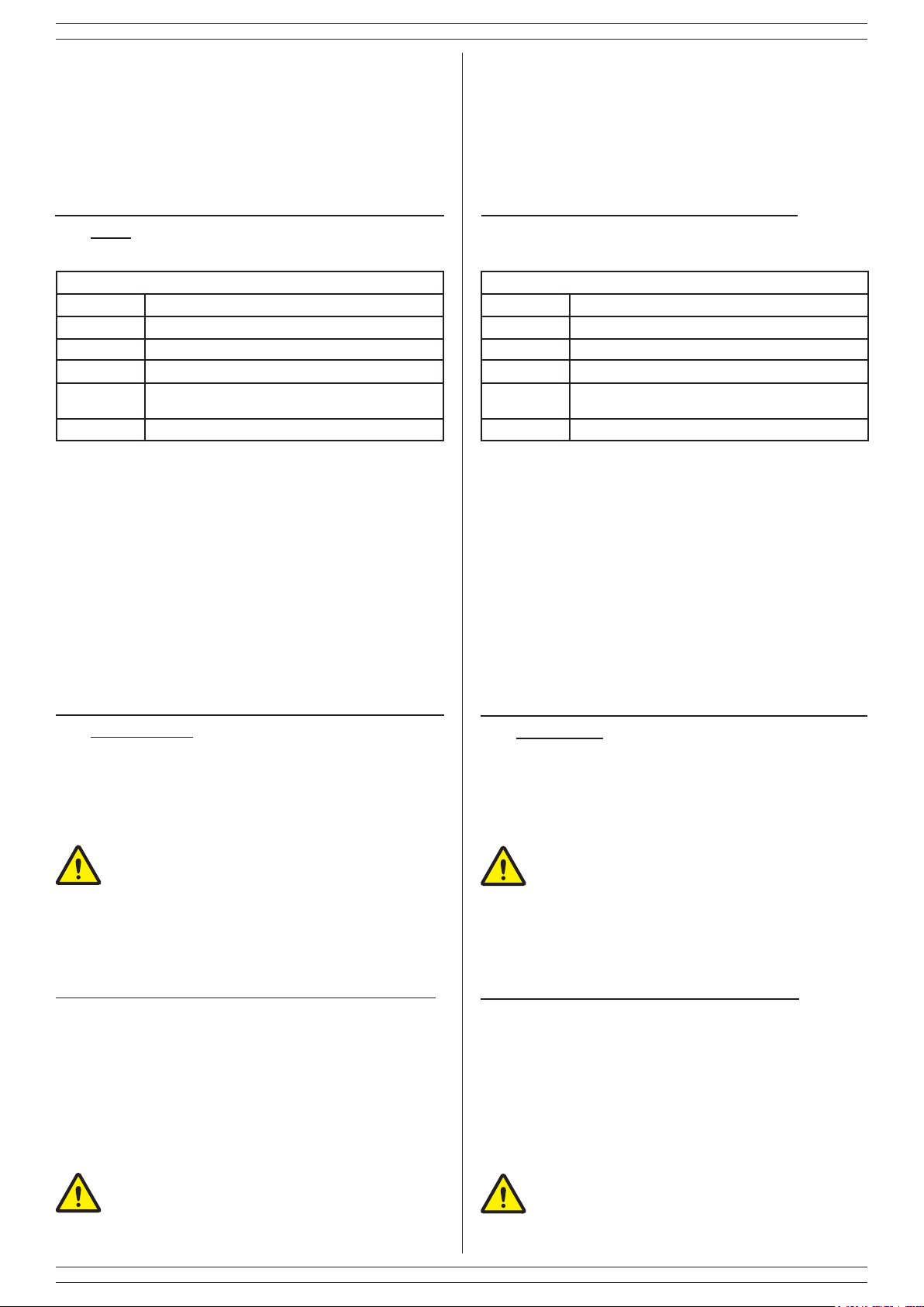
3 LOGICA DI FUNZIONAMENTO DEI
LED
3.1 LED DI ALLARME
Tabella 4
Lampeggi Signicato
1 esistenza in vita ogni 60 secondi
3 batteria scarica (<12V) o assente o guasta
6 alimentazione < 11V;
9
12 barriera IR antischiuma ostruita
NOTA:
il LED di allarme segnala anche la presenza contemporanea
di più anomalie. In caso siano presenti più anomalie, il LED
effettuerà una pausa di 2 secondi tra una sequenza e l'altra.
speaker o driver guasti solo se l’alimentazione
supera gli 11V
NOTES:
in case of absence of available links from the control panel, the
AL terminal block can be linked to 12 Vdc or to GND (according
to the DIP1 programming) and wired inside the control panel
to the terminal block reserved for the siren or to a relay. This
type of connection, however, could compromise the durability
of the battery.
3 LED SIGNALLING MEANING
3.1 ALARM LED
Table 4
Flashes Meaning
1 work signalling each minute
3 low (<12V), absent or failure battery
6 operating voltage < 11V
9
12 anti-foam IR beam obstructed
NOTE:
The alarm LED could indicate the simultaneous presence of
multiple anomalies. in case of more issues, the LED will pause
for 2 seconds between each sequence.
speaker or driver failure only if operating voltage il
plus than 11V
3.2 LED DI STATO
Il LED di stato permette di visualizzare lo stato dell’impianto
(secondo la programmazione del relativo dip).
Al raggiungimento di 5 allarmi consecutivi all’interno di una
stessa attivazione, il LED comincia a lampeggiare.
Per ripristinare la normale visualizzazione è necessario
effettuare un inserimento o un disinserimento.
4. MANUTENZIONE E VERIFICHE PERIODICHE
4.1 SOSTITUZIONE PERIODICA DELLA BATTERIA
Al ne di garantire il corretto funzionamento della sirena, è necessario sostituire la batteria tampone ogni 2 anni
ATTENZIONE! Per rimuovere sporcizie particolar-
mente evidenti NON utilizzare prodotti a base di
cloro, prodotti abrasivi oppure alcool.
1. Pulire il coperchio con un panno inumidito con acqua.
2. Ripassare con un panno asciutto.
5. SMALTIMENTO E ROTTAMAZIONE
3.2 STATUS LED
The status LED can display the system status (according to the
relative dip).
On reaching 5 consecutive alarms within the same activation,
the LED begins to blink.
To restore the normal display you need to arm or disarm the
system.
4. MAINTENANCE AND PERIODIC
CHECKS
4.1 PERIODIC REPLACEMENT OF THE BATTERY
In order to guarantee the ensure the correct work of the siren, is
compulsory to replace the battert every 2 years.
IMPORTANT!
Do NOT use chlorine-based or abrasive products
or alcohol to remove particularly noticeable dirt.
1. Clean the lid with a cloth dampened with water.
2. 2. Wipe with a dry cloth.
5. DISPOSAL AND SCRAPPING
5.1 DISINSTALLAZIONE
1. Svitare le viti che tengono sso il coperchio frontale e rimuoverlo.
2. Scollegare la scheda: sulla morsettiera scollegare tutti i morsetti (v. Fig. 3).
3. Dividere le parti in base alla loro tipologia e smaltirle in accordo con le leggi vigenti.
ATTENZIONE!
Non disperdere nell’ambiente i componenti ed ogni
altro materiale del prodotto.
Rivolgersi a consorzi abilitati allo smaltimento ed al riciclaggio dei materiali.
5.1 DISMANTLING
1. Unscrew the screws that fasten the front lid and remove
it.
2. Disconnect the board: disconnect all the terminals on the
terminal block (see Fig. 3).
3. Divide the parts by type and dispose of them in accordance
with applicable laws.
IMPORTANT!
Do not dispose of the components or any other
product material in the environment.
Seek the assistance of companies authorised to dispose of
and recycle waste materials.
11
Page 12

001530/00856AD
LINCE ITALIA S.p.A
Via Variante di Cancelliera, snc
00040 ARICCIA (Roma)
Tel. +39 06 9301801
Fax +39 06 930180232
[email protected]
www.lince.net
 Loading...