

Lincat SLR6, SLR9, Silverlink 600, SLR9C, SLR6C Installation, Operating, Servicing And Conversion Instructions
Page 1
Installation, Operating, Servicing and
Conversion Instructions
Silverlink 600 Gas Ranges
SLR6, SLR6C, SLR9 and SLR9C
Please make a note of your product details for
future use:
Date Purchased: _
Number:
Dealer:
_
IS514 ECN4292 Page 1 of 20
_
Page 2
Dear Customer,
This is just one of over 450 different items of catering equipment available
which is constantly being extended and improved. Details are available from
Used for the purposes for which it is intended, and with careful maintenance
as outlined in this User Guide, your Lincat product will give you years of
trouble free service.
NOTE
Thank you for purchasing this Lincat product.
your local distributor or direct from us.
IMPORTANT INFORMATION
Please read all of the safety and operating instructions carefully before using this
product. Please pay particular attention to all sections of this User Guide that carry
warning symbols and notices.
WARNING!
This is a Warning symbol. This symbol is used throughout the user guide
whenever there is a risk of personal injury. Ensure that these warnings are
read and understood at all times.
CAUTION!
This is a Caution symbol. This symbol is used throughout the user guide whenever
there is a risk damaging your Lincat product. Ensure that these warnings are read
and understood at all times.
NOTE:
This is a Note symbol. This symbol is used throughout the user guide to provide
additional information, hints and tips.
KEEP THIS MANUAL FOR FUTURE REFERENCE
IS514 ECN4292 Page 2 of 20
Page 3
CONTENTS
WARNINGS AND PRECAUTIONS
Contents Page
Customer Information……………………………………………………… 2
Warnings and Precautions……………………………………………...... 3
Technical Data………………………………………………………………. 4
Commissioning…………………………………………………………...... 5
Check List of Enclosures…………………………………………………... 5
Serial Number…………………………………………………….………….. 5
Installation…………………………………………………….……………… 6
User…………………………………………………………………………….. 7-9
Servicing ……………………………………………………………………… 10-14
Conversion…………………………………………………………….……… 15-16
Spare Parts List……………………………………………………………… 17
Fault Finding…………………………………………………………………. 18
Accessories………………………………………………………….………. 19
Service information…………………………………………………………. 20
Guarantee………………………………………………………….………….. 20
It is mandatory that all appliances are installed, commissioned and serviced by a
qualified and competent person as defined by the regulations in force in the country of
installation.
Failure to comply will invalidate the warranty.
WARNING!
This appliance must be installed by a competent installation engineer in accordance with the
installation instructions, and should conform to the following requirements:
Do not obstruct or block the appliance flue.
Installation must include sufficient ventilation to prevent the occurrence of unacceptable
concentrations of substances harmful to health in the room in which they are installed.
It is recommended that this appliance is sited under an extraction canopy for the removal of
combustion products
After operation, some parts of the appliance will remain hot for a period of time. Please take
care to avoid accidental burns.
CAUTION!
All equipment must be earthed (where applicable) to prevent electric shock.
Do not connect directly to any flue, ducting or mechanical extraction system.
Installation should allow for a sufficient flow of fresh air for gas combustion.
Parts which have been protected by the manufacturer or his agent must not be adjusted by
the installer or user.
The appliance is designated Category 1 and is not intended for conversion from one gas type
to another.
IS514 ECN4292 Page 3 of 20
Page 4
TECHNICAL DATA
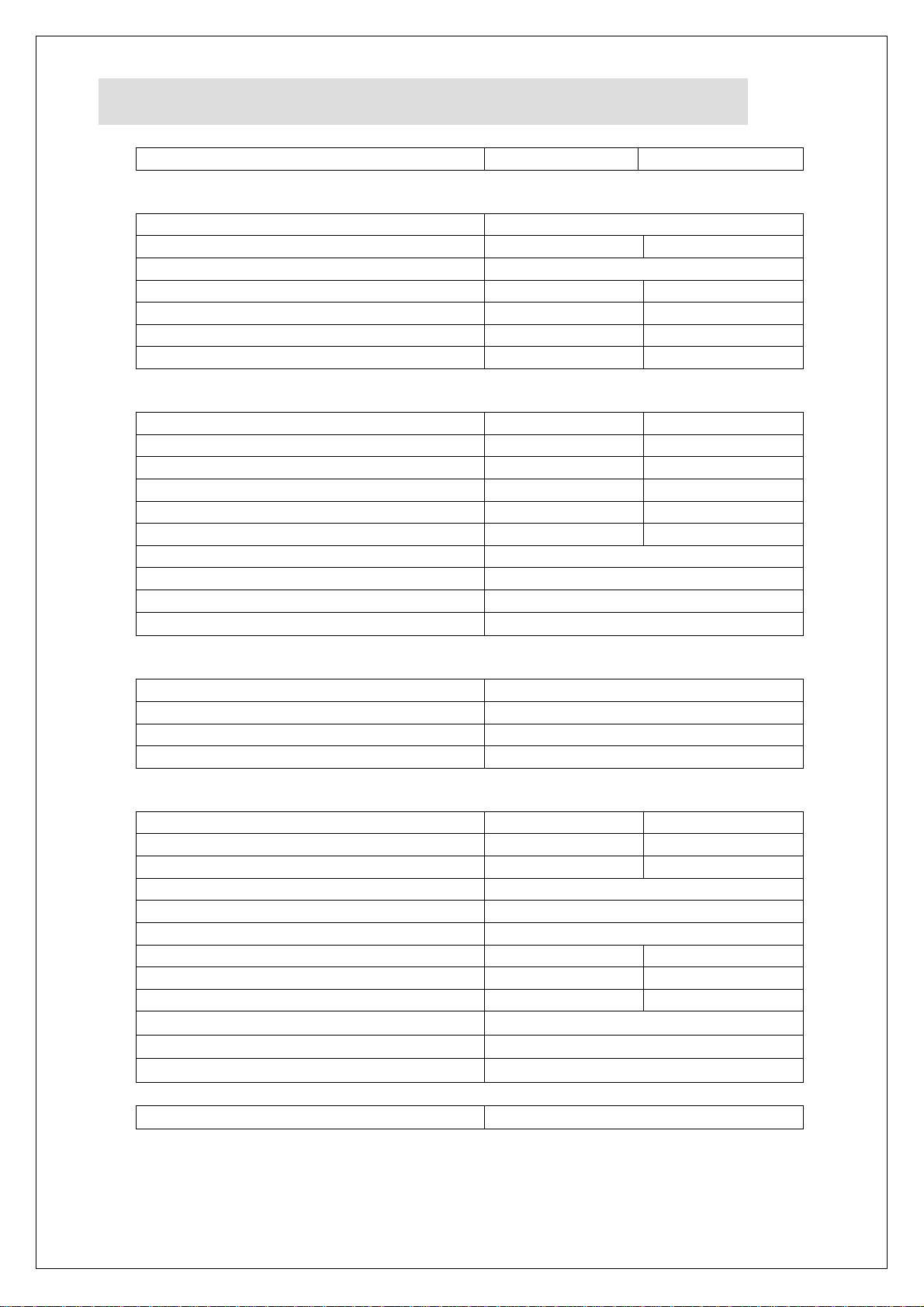
Model
SLR6
SLR9
Overall height (mm)
925 to hob 960 to pan support
Width (mm)
600
900
Depth (mm)
600
Weight (kg)
69kg (Net)
85kg (Net)
Hob cooking surface w x d (mm)
590 x 500
890 x 500
Usable oven capacity w x d x h (mm)
425 x 345 x 400
660 x 345 x 400
Oven shelf size (mm)
420 x 345
700 x 345
Total heat input Natural(Gross)
23.8 kW
35.5kW
Total heat input Propane(Gross)
23.8 kW
35.5kW
Total heat input Butane(Gross)
20.6kW
30.7kW
Oven rating Natural(Gross)
5.8 kW
8.5 kW
Oven rating Propane(Gross)
5.8 kW
8.5 kW
Oven rating Butane(Gross)
5.8 kW
8.5 kW
Hob rating, per burner Natural(Gross)
4.5 kW
Hob rating, per burner Propane(Gross)
4.5 kW
Hob rating, per burner Butane(Gross)
3.7kW
Hob Low Rate (all gasses)
0.85kW
Gas inlet connection
RP½ (½" BSP)
Supply Pressure - Natural
20mbar
Supply Pressure - Propane
37 mbar
Supply Pressure - Butane
28-30mbar
Total gas rate – Natural
2.27 m3 h-1
3.38 m3 h-1
Total gas rate – Propane
1.70 kg h-1
2.54 kg h-1
Total gas rate – Butane
1.50 kg h-1
2.23 kg h-1
Hob burner gas rate - Natural
0.43m3h-1
Hob burner gas rate - Propane
0.32kg h-1
Hob burner gas rate - Butane
0.27kg h-1
Oven burner gas rate - Natural
0.55m3h-1
0.81m3h-1
Oven burner gas rate - Propane
0.41kg h-1
0.61kg h-1
Oven burner gas rate - Butane
0.42kg h-1
0.62kg h-1
Hob Low Rate Natural
0.08m3h-1
Hob Low Rate Propane
0.06kg h-1
Hob Low Rate Butane
0.06kg h-1
Oven temperature range
130 – 250 C
Dimensions
Heat Input
Connection and Operating Pressures
Gas Consumption
IS514 ECN4292 Page 4 of 20
Page 5
COMMISSIONING
CHECK LIST OF ENCLOSURES
Model
SLR6
SLR9
Tick
Warranty Card
1
1
Pan Supports
2
3
User Instructions
1
1
SERIAL NUMBER
Serial Number
NOTE
PREPARATION
Remove all packaging and protective coatings prior to installation.
Check that the hob burner parts, pan supports and shelves are correctly located.
VENTILATION
The area in which this equipment is to be installed should have sufficient fixed ventilation to
comply with local legislation requirements. It is recommended that a room, or internal space,
be provided with a minimum free area of 4.5cm2 per kW (3,400Btu/hr) of total heat input.
Each appliance manufactured at Lincat has a unique identifying number found in the top
right hand corner of the data plate attached at the rear of the appliance. Please record
that number in the space provided should it be required for future reference.
IS514 ECN4292 Page 5 of 20
Page 6
INSTALLATION
SITING
The installer must ensure that all regulations are met and that there is an unobstructed
minimum distance of 1000mm from the top of the flue to the ceiling, which must be of noncombustible material.
The appliance should be installed on a level surface ensuring the unit is stable and firmly
located.
Any partitions, walls or kitchen furniture in close proximity must be of non-combustible
materials and not be closer than 50mm from the sides and rear of the flue.
GAS SUPPLY AND CONNECTION
Connection is at the rear of the unit via a Rp½ (½" BSP)
Connection shall comply with local regulations.
The hose shall be periodically examined and replaced as necessary.
When making the connection to the appliance an isolating cock should be fitted into
the supply line close to the unit, for emergency shutdown or servicing purposes.
An equipotential bonding terminal is provided to allow cross bonding with other
equipment.
SUPPLY PRESSURES
The appliances are intended to be connected directly to the gas supply without further
adjustment for those countries where the supply pressure does not exceed the pressures
as detailed above.
For those destination countries where the supply pressure exceeds the supply
pressures given in the Technical Data above a regulator must be fitted and the
supply pressure set to the pressures detailed.
For the purposes of proving connection integrity access to the pressure test nipple is as
follows:
To gain access to the gas pressure test nipple open the oven door/s.
Remove the control knobs.
Remove the screws securing the fascia and remove the oven ignitor lead.
The test nipple is found on the manifold rail
FIRST TIME LIGHTING
The procedure for first time lighting may only be carried out by registered personnel.
To light any individual burner it may be necessary to purge all pipe work of air.
To do this, depress and hold in the full on position as many controls knobs as possible
until there is evidence of free gas flow. Upon detection of gas flow return all but one control
knobs to the 'OFF' position and light the gas at the burner corresponding to the control
knob in the depressed position. When the gas at the burner is burning correctly shut it
down and repeat the lighting process for the remaining burners.
INSTRUCTION TO USER
Ensure that the person responsible understands how to light, safely operate, clean and
shutdown the appliance and is made aware of the position and operation of the gas
isolating cock in the event of an emergency.
IS514 ECN4292 Page 6 of 20
Page 7
USER INSTRUCTION
APPLIANCE USE
This appliance is only for professional use and should only be used by qualified personnel.
Ensure that the person responsible understands how to light, safely operate, clean and
shutdown the appliance and is made aware of the position and operation of the gas isolating
cock in the event of an emergency.
Ensure that all controls have free and easy movement, if not contact a qualified service
engineer.
This appliance hob is intended to be used for heating of culinary preparations that can be
cooked by means of frying, simmering or boiling in suitable pans and MUST NOT be used
for any other purpose.
The oven cavity is intended for the cooking of culinary preparations by means of braising,
roasting and baking either directly on the oven shelves or in suitable none combustible
containers approved for containing food products. The oven MUST NOT be used for any
other purpose.
Operators of the appliance must not leave combustible materials directly in the cooking
areas of the appliance when in use.
Ensure the pan supports are centrally placed on the hob to.
It is recommended that a burner is lit first before placing large pans over the burner.
It is not recommended that multiple lit hob burners are covered at any one time by
large gastronome pans or detachable griddle plates.
PAN PLACEMENT
Pans should be placed centrally on the pan support in relation to the burner for maximum
efficiency.
PAN SIZES
The recommended pan base diameters are no smaller than 150mm and no larger than
400mm.
Pans should be placed centrally on the pan support in relation to the burner for maximum
efficiency.
OPERATION OF THE APPLIANCE
The appliance should not be left unattended when in use for any lengthy period of
time.
Pans should only be filled to a level no more than to prevent a boil over situation.
Periodically inspect liquid volumes to prevent a boil dry situation.
Frying of product should never be left unattended.
Use hand and arm protective when handling hot pans to avoid injuries from burns.
LIGHTING SEQUENCE
Please ensure that the gas isolation valve for the appliance is turned to the open position
before attempting to light this unit.
HOB BURNERS
From the OFF position: press and turn the control knob anti-clockwise to any position
between the two stylized flames to allow gas through to the burner.
Maintaining the control knob depressed, manually light the gas at the burner using a
taper or piezo ignitor wand.
IS514 ECN4292 Page 7 of 20
Page 8

On establishing a flame at the burner, keep the knob depressed for approximately 15
seconds then release. The burner should remain lit.
If the appliance has stood unused for any length of time it may be necessary to purge the
burner feed pipes of air. To purge the burner feed pipes of air depress and rotate a
control knob to the full on position. Maintain the knob in the depressed position for 2030seconds and then light the gas at the burner. Repeat as necessary until the gas
ignites.
OVEN BURNER
Open the oven door/s
From the OFF position press and turn the oven thermostat knob anti-clockwise to the
stylized star position to allow gas to flow through to the oven burner.
Maintaining the control knob depressed, push the oven ignitor button until an audible click
is heard. A spark will be generated at the oven burner. The gas at the oven burner should
light. It may be necessary to repeat the ignition process a number of times until the gas
lights.
On establishing the flame at the oven burner, maintain the thermostat knob in a depressed
state for approximately 15 seconds and then release the control knob. The gas should
remain lit.
Rotate the thermostat knob to the desired temperature setting.
OVEN TEMPERATURES
The temperatures on the thermostat knob are a guide and generally reflect the
temperature at the centre of the oven. The temperatures in the oven will vary from
top to bottom. It may be necessary to periodically rotate product being cooked to
ensure even cooking.
OPERATION OF THE APPLIANCE
The appliance should not be left unattended when in use for any lengthy period of
time.
Pans should only be filled to a level no more than to prevent a boil over situation.
Periodically inspect liquid volumes to prevent a boil dry situation.
Frying of product should never be left unattended.
Use hand and arm protective when handling hot pans to avoid injuries from burns.
OVEN DOORS
Care must be taken when opening the oven doors when the appliance is in
operation due to the rapid escape of hot air.
Use hand and arm protective when handling hot roasting pans and baking trays to
avoid injuries from burns.
SHUT DOWN
To shut down the appliance rotate all control knobs clockwise to the OFF position. The gas
supply stopcock or bottle valve should now be closed.
IS514 ECN4292 Page 8 of 20
Page 9

CLEANING
Do not use a water jet or steam cleaner, and do not immerse this appliance.
Clean all panels with warm water and mild detergent, do not use abrasive
materials. Dry with a soft cloth.
It is important that users of the appliance systematically check and clean down as
necessary areas of the hob and oven cavity that have accumulated oils, fats and
other combustible debris from previous cooking. Particular attention must be paid to
the burner head ports. Ensure they are always clear. Ensure the appliance and all
its parts are in a cold state before commencing any cleaning routine.
Areas to Check
BURNER CAPS – Check burner caps are clean and centrally seated on the burner
head
BURNER HEADS – The burner heads can only be fitted in one orientation onto
the burner body. As a guide the recess with the two ports aligns with the
thermocouple.
PAN SUPPORTS – The pan supports are manufactured from cast iron and are
heavy. For ease of cleaning they can be removed from the appliance and placed
in a suitable dish washer.
OVEN SHELVES – The shelves can easily be removed for routine cleaning.
Stubborn burned on deposits can be cleaned using suitable approved cleaning
agents and scourers
OVEN BASE TRAY – Can be easily removed for cleaning
OVEN CAVITY – To clean the oven cavity remove the shelves and base tray
and remove any solids and accumulated fats, oils and spillages.
IS514 ECN4292 Page 9 of 20
Page 10
SERVICING
FF
CC
SS
The replacement of serviceable parts can only be carried out by registered authorised
personnel and must and must be in possession of up to date licensing.
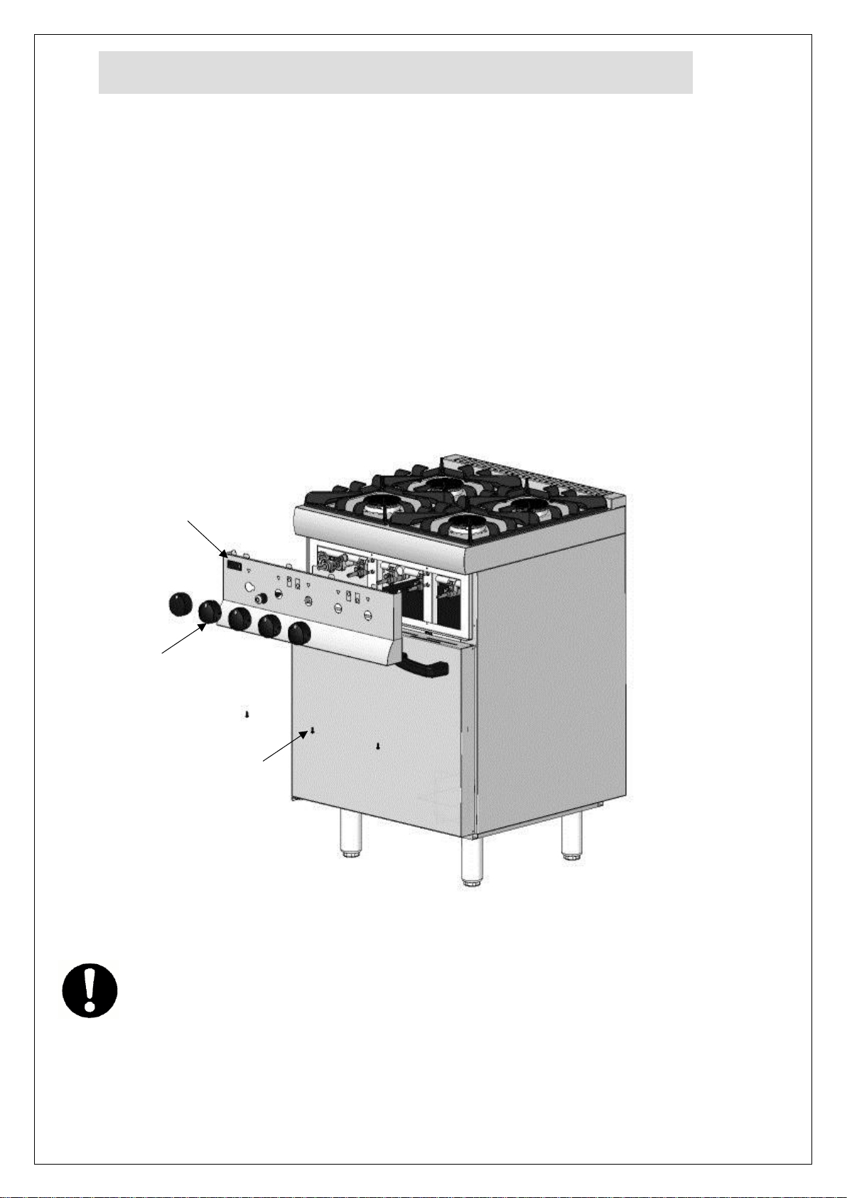
FASCIA PANEL REMOVAL
Care should be taken when removing the fascia panel as the oven ignitor lead will be
attached to the ignitor.
Open the oven door/s
Remove the screws SS situated underside of the fascia panel FF.
Remove the control knobs CC by pulling free from the valve spindles. Be
aware spring clips are fitted to each control knob
Tilt the fascia panel from the bottom up and then pull clear of the hob top.
Disconnect the ignitor lead from the ignitor button and temporarily tie to the manifold
rail.
Access to the valves, thermostat, pipe work and thermocouples are from the front
aperture
OPERATIONAL CHECK
Commissioning must include an operational check of all controls.
Check that each burner can be lit at both full rate and low rates
Check that each burner will remain lit when turned to low rate
To access parts internally remove the control knobs. Remove the fascia panel securing
IS514 ECN4292 Page 10 of 20
Page 11
screws from the underside of the fascia panel.
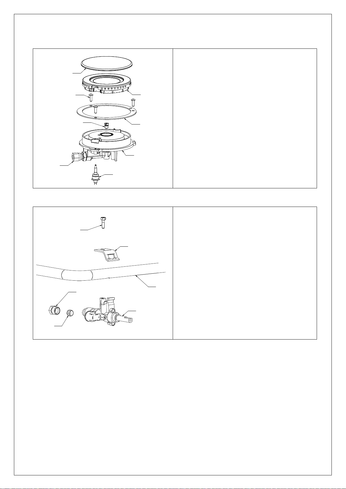
To replace the burner and its parts
Remove the burner cap 'BU09'
Remove the burner head 'BU08'
Remove the 3 screws 'FAS601’
Remove the control knobs from the valves
Remove the fascia panel
Loosen the burner feed pipe connection nut on
'CO15'
Loosen the thermocouple nut 'TC01' connection at the
corresponding valve
Remove the burner body 'BU07' and the gasket 'FAS351'
Remove the injector 'JExx' (dependent on gas type) from
the burner body
Remove the thermocouple 'TC01' from the burner body
Remove the remain parts of 'CO15' from the burner
body
Replace and reassemble any or all
parts as applicable
To remove the valve and its parts:
Remove the control knobs Remove the
fascia panel
Loosen the thermocouple 'TC01' nut at the valve body
'VA10'
Loosen the burner feed pipe nut 'BU159' at the
valve
Remove the valve clamp screw 'BU209'
Lift the valve clamp 'BU208' from the valve and the
manifold 'MAxx' (dependent on appliance)
Free the valve from the manifold Replace and
reassemble parts as necessary
Perform leak test to prove integrity of joints
Servicing of Valve
To service the valve carefully remove the niting cap
screws and withdraw the spindle from the valve
Clean old grease and re-grease with suitable gas
compliant compound
Re-assemble and perform soundness check
CO15
TC01
BU07
FAS351
FAS601
BU09
BU08
JExx
MAxx
BU208
BU159
VA10
BU209
BU158
BURNER COMPONENTS
VALVE COMPONENTS – SERVICING RECOMMENDED EVERY 6 MONTHS
IS514 ECN4292 Page 11 of 20
Page 12
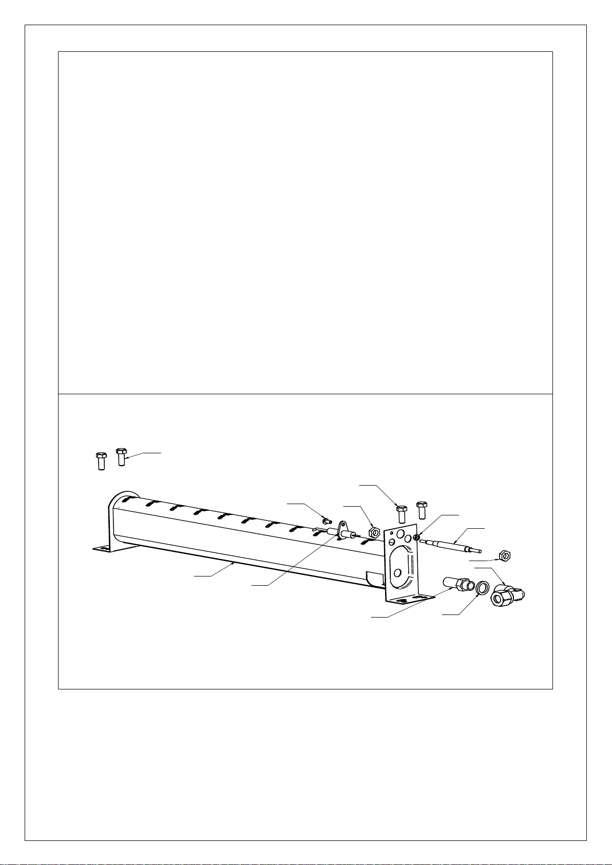
OVEN BURNER COMPONENTS
Ignitor Electrode
To remove the ignitor (IG16) electrode remove the lead from the electrode
Remove the retaining screw FAS360 and nut FAS016
Replace the ignitor, secure and refit the lead
Thermocouple
Loosen the lock nut at the tip side of the thermocouple (TC30) and withdraw from the burner
bracket
Remover the control knobs and fascia panel
Loosen the thermocouple nut at the
thermostat
Bind the new thermocouple thermostat end to the tip of the old thermocouple and gently feed old
and new through into position
Remove the binding and the old thermocouple
Make good the thermocouple connection at the thermostat
Lock the thermocouple head to the burner bracket to the dimensions details. See thermocouple
setting
Oven Burner
Isolate the gas supply from the appliance
Remove the thermocouple and ignitor
electrode
Remove the burner injector ( see Gas Conversion)
Remove the burner retaining screws
Replace the new burner and refit parts
Reconnect the gas supply
Check joints for leak free integrity
FAS609
BUxx
FAS630
IG16
TC30
JExx
WA13
CO133
FAS016
TC30
TC30
FAS609
IS514 ECN4292 Page 12 of 20
Page 13
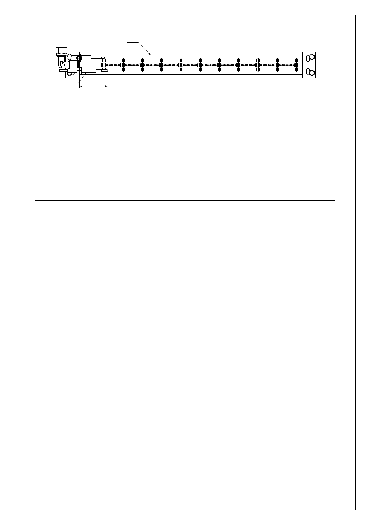
OVEN THERMOCOUPLE SETTING
To correctly position the thermocouple the lock nuts will require setting on the barrel of the
thermocouple body
Feed the replaced thermocouple as detailed above
Position the thermocouple as detailed above and to the dimension given
Lock the thermocouple into place
Light the oven burner and set the thermostat to approximately 190oC
Allow the oven to reach temperature with the doors shut and turn the thermostat to the lowest
setting (130oC)
Check that the flame remains established at the burner
If the flame at the burner at the lowest setting drops out minor adjustments may be necessary
to maintain the flame
TC30
43 ±1
BUxx
IS514 ECN4292 Page 13 of 20
Page 14
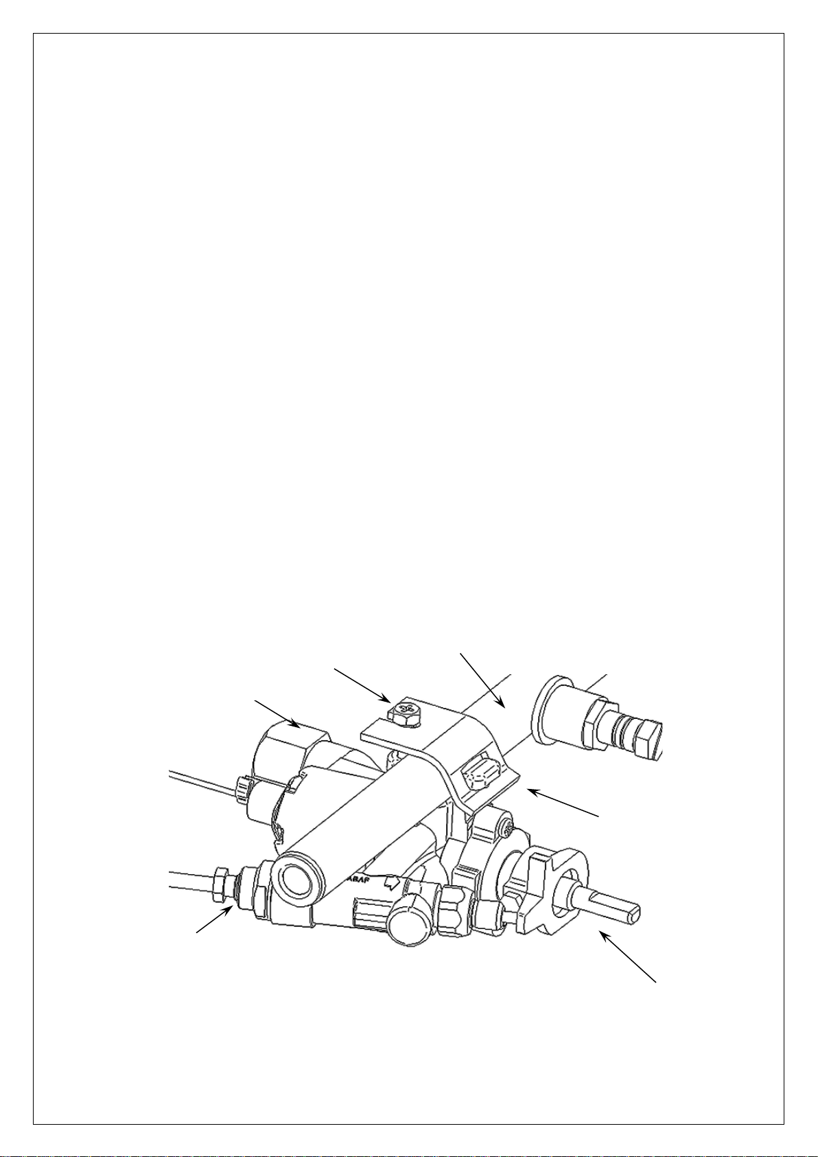
THERMOSTAT - SERVICING RECOMMENDED EVERY 6 MONTHS
BU208
TH17C
BU209
TH07
TC30
MAxx
Isolate the gas supply to the appliance
To replace the thermostat remove the control knobs and fascia panel supporting the
thermostat body and loosen the thermostat gas feed nut TH17C
Loosen the clamp screw BU209 sufficiently to free the thermostat bracket BU208
Free the thermostat TH07 from the manifold MAxx
Free the thermocouple TC30 from the thermostat body
Free the thermostat bulb from the oven cavity bracket (remove oven shelves to ease
access)
Feed the thermostat bulb and capillary through the top of the oven cavity liner withdraw the
thermostat
Connect the thermocouple to the new thermostat
Fit the new thermostat to the manifold and secure ensuring the seal is fitted to the saddle of
the thermostat
Carefully unwind the capillary and feed the thermostat bulb through the top of the liner and
reset the bulb in its bracket. Ensure all capillary slack is fed back above the top liner
Make good the gas feed connection nut to the thermostat. Reconnect the gas supply
Check joints for leak free integrity
Refit the fascia panel and control knobs
Check the low flame function of the oven burner as detailed in thermocouple setting
Servicing of Valve
To service the valve carefully remove the niting cap screws and withdraw the spindle
from the valve
Clean old grease and re-grease with suitable gas compliant compound
Re-assemble and perform soundness check
IS514 ECN4292 Page 14 of 20
Page 15
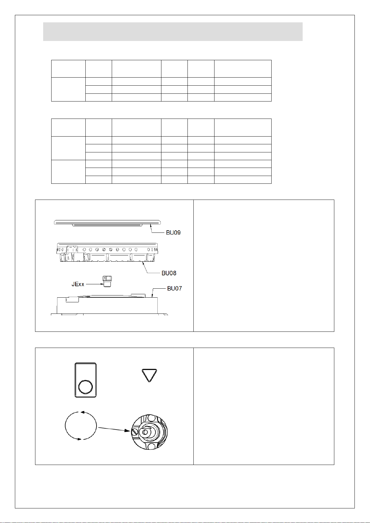
CONVERSION
Model
Gas
Inlet
Pressure
Mark
Part Number
All
G20
20mbar
1.64
164
JE155
G30
28-30mbar
0.98
98
JE157
G31
37mbar
1.10
110
JE156
Model
Gas
Inlet
Pressure
Mark
Part Number
SLR6
G20
20mbar
1.90
190
JE107
G30
28-30mbar
1.25
125
JE109
G31
37mbar
1.25
125
JE109
SLR9
G20
20mbar
2.40
240
JE50
G30
28-30mbar
1.50
150
JE51
G31
37mbar
1.50
150
JE51
The burner injector is fitted to the base of
the burner body
Remove the burner cap 'BU09'
Remove the burner head 'BU08
Access to the burner injector 'JExx' is
through the venturi to the base of the
burner body 'BU07'.
To remove, un-screw by turning
anticlockwise
The correct size of the injector
appertaining to gas type is marked on one
of the hexagonal faces of the injector.
Replace with the correct injector applicable
to gas type and reassemble burner parts
Remove the control knobs
Adjustment for conversion from Natural
gas to Propane or Butane:
Rotate the bypass injector clockwise full
home, do not over tighten.
Replace the control knobs
Adjustment for conversion from Propane or
Butane to Natural gas :
Ensure the bypass injector is fully home,
do not over tighten
Rotate the bypass injector between 1/3 to
1/2 of a turn anticlockwise
Replace the control knobs
HOB BURNER INJECTOR CHANGES
OVEN BURNER INJECTOR CHANGES
HOB BURNER INJECTOR
BYPASS INJECTOR ADJUSTMENT
OVEN BURNER INJECTOR
IS514 ECN4292 Page 15 of 20
Page 16
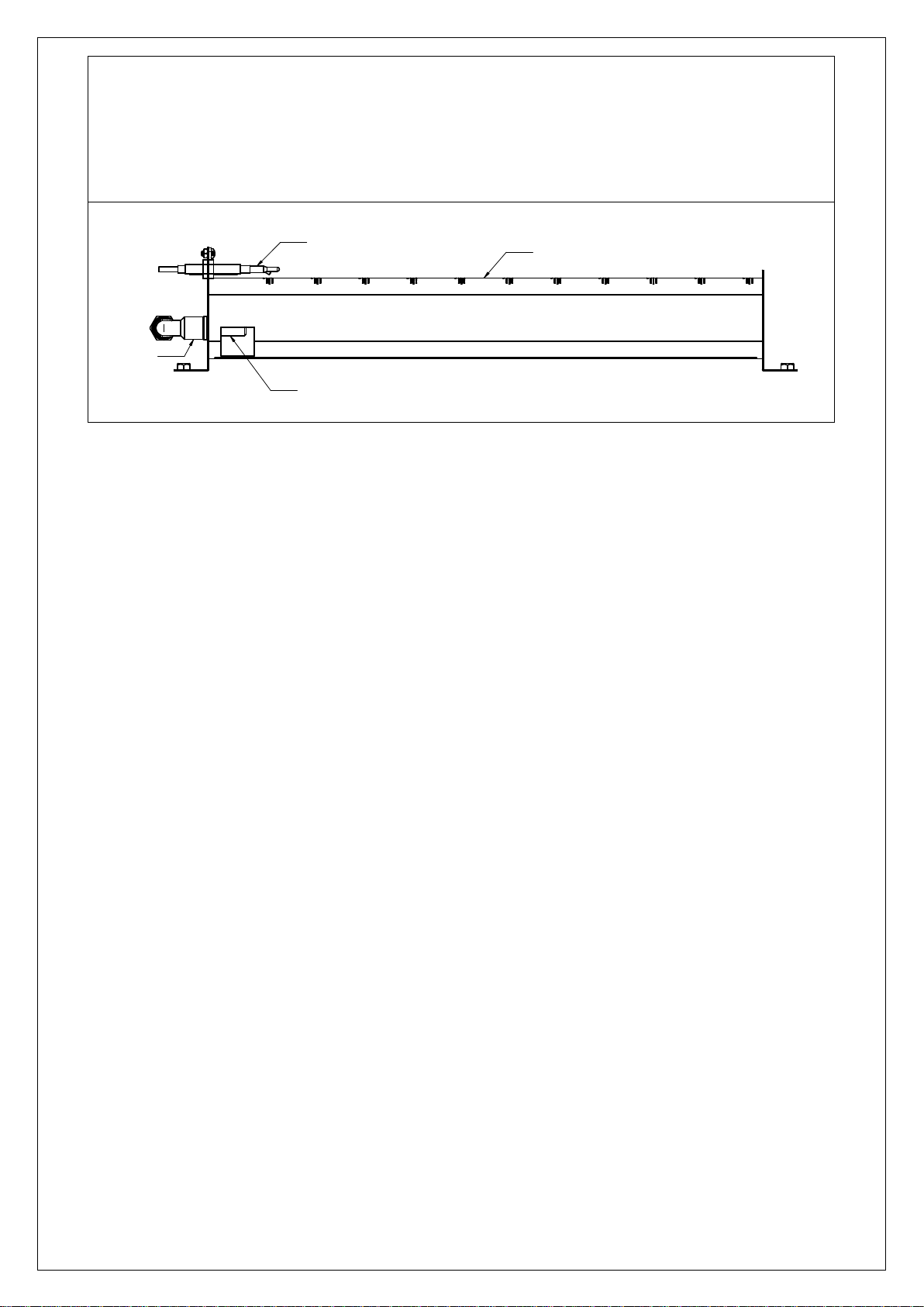
To replace the oven burner injector Loosen the nut on the feed elbow CO133
Free the elbow and injector from the burner BUxx Free the injector JExx from the elbow
Replace the injector applicable to the gas type with the washer WA13 and tighten against
the elbow
Refit the injector assembly to the burner Reconnect the elbow nut
Check joints for leak free integrity
JExx
TC30
BUxx
CO133
Replace gas specific labels for which the appliance has been converted
Replace data plate corresponding to gas type
IS514 ECN4292 Page 16 of 20
Page 17
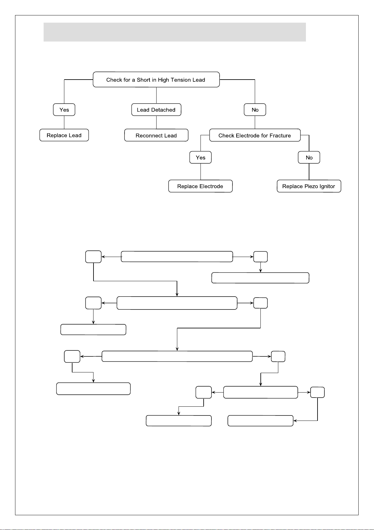
FAULT FINDING
Yes
Is There Gas at the Burner?
No
Check Injector for Blockages
Yes
Are Thermocouple Connections Loose?
No
Tighten Connections
Yes
Is the Thermocouple Voltage Less than 5mV?
No
Replace Thermocouple
Yes
Is the Valve Damaged?
No
Replace Valve
Recheck System
Piezo oven ignitor not sparking
Burner/s will not light or stay lit
IS514 ECN4292 Page 17 of 20
Page 18
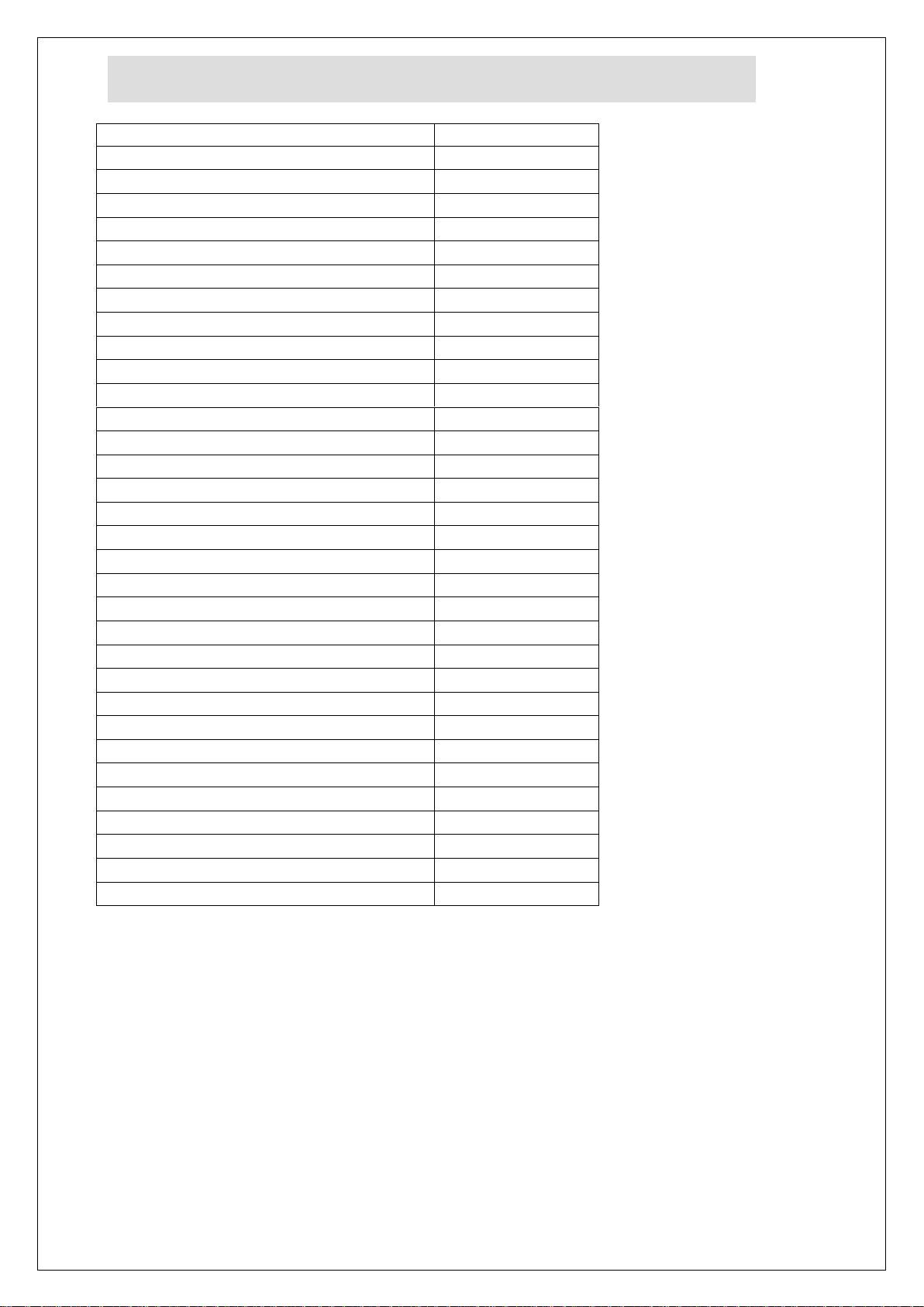
SPARE PARTS LIST
Description
Part number
Hob burner body
BU07
Hob Burner head
BU08
Hob burner cap
BU09
Door bush
BU55
Oven burner – SLR9
BU78
Oven burner – SLR6
BU86
Fixed castor
CA86
Adjustable leg
FE29
Piezo ignitor
IG12
Ignitor electrode
IG16
Ignitor lead
IG18
Manual of Instruction
IS514
Oven injector (Natural) SLR6
JE107
Oven injector (Propane) SLR6
JE109
Oven injector (Butane) SLR6
JE109
Hob injector (Natural)
JE155
Hob injector (Propane)
JE156
Hob injector (Butane)
JE157
Oven injector (Natural) SLR9
JE50
Oven injector (Propane) SLR9
JE51
Oven injector (Butane) SLR9
JE51
Thermostat control knob
KN191
Hob control knob
KN196
Pan support
PA25
Oven shelf SLR6
SH87
Oven shelf SLR9
SH88
Side rack ovens
SR11
Hob thermocouple
TC01
Oven thermocouple
TC30
Thermostat (complete)
TH07
Hob Valve (complete)
VA10
Copper Washer
WA13
IS514 ECN4292 Page 18 of 20
Page 19
ACCESSORIES
Part Number
Description
Used on
SLR6/SB
PLATE SHELF
SLR6
SLR9/SB
PLATE SHELF
SLR9
IS514 ECN4292 Page 19 of 20
Page 20

SERVICE INFORMATION
Product code
All available on serial plate
Type number
Serial number
For help with the installation, maintenance and use of your Lincat equipment,
please contact our service department:
For non-UK customers, please contact your local Lincat dealer
All service work, other than routine cleaning MUST be carried out by qualified
personnel and a record kept of any remedial actions taken and at least cover the
requirements of the service schedule of this document. We cannot accept
responsibility for work carried out by other persons.
To ensure your service enquiry is handled as efficiently as possible, please tell us:
Brief details of the problem
Lincat reserve the right to carry out any work under warranty, given reasonable
access to the appliance, during normal working hours, Monday to Friday, 08:30 to
17:00.
DECLARATION
All Lincat products capable of burning gaseous fuels, satisfy the requirements of the
Gas Appliance Regulations 2016/426.
UK: 01522 875520
GUARANTEE
This unit carries a comprehensive UK mainland warranty. The guarantee is in
addition to, and does not diminish your statutory or legal rights. Contact Lincat for
terms and conditions
The guarantee does not cover:
Accidental damage, misuse or use not in accordance with the manufacturer’s
instructions
Consumable items (such as filters, glass, bulbs, slot toaster elements and
door seals.)
Damage due to incorrect installation, modification, unauthorised service work
or damage due to scale, food debris build-up, etc.
The manufacturer disclaims any liability for incidental, or consequential damages.
Attendance is based on reasonable access to the appliance to allow the authorised
personnel to carry out the warranty work.
Service calls to equipment under warranty will be carried out in accordance with the
conditions of sale. Unless otherwise specified, a maximum of 15 minutes of administrative
time, not spent directly carrying out servicing work, is provided for within the warranty. Any
requirement for staff attending the call to spend greater time than 15 minutes due to
administrative requirements, such as on health and safety risk assessments, will be
chargeable at the prevailing rate.
IS514 ECN4292 Page 20 of 20
 Loading...