

Page 1
Please make a note of your product details for
future use:
Date Purchased: _________________________
Model Number: __________________________
Serial Number: __________________________
Dealer:
_________________________________
_______________________________________
Installation, Operating and Servicing
Instructions
Phoenix Electric Induction Range
PHER01-A002, PHER01/SPH-A001 AND
PHER02-A001.
IS707 ECN 4624 1
Page 2
CONTENTS
Important Information
2
Warnings and Precautions
3
Technical Data
3
Checklist of Enclosures
4
Installation and Commissioning
4-5
Operating Instructions
6-11
Cleaning
11
Servicing, Maintenance and Component Replacement
12
Fault Finding
12
Spare Parts List
12
Service Information and Guarantee
13
IMPORTANT INFORMATION
Read these instructions carefully before using this product, paying particular
attention to all sections that carry warning symbols, caution symbols and notices.
Ensure that these are understood at all times.
WARNING!
This symbol is used whenever there is a risk of personal injury.
CAUTION!
This symbol is used whenever there is a risk of damaging your Lincat product.
NOTE:
This symbol is used to provide additional information, hints and tips.
KEEP THIS MANUAL FOR FUTURE REFERENCE
IS707 ECN 4624 2
Page 3

WARNINGS AND PRECAUTIONS
TECHNICAL DATA
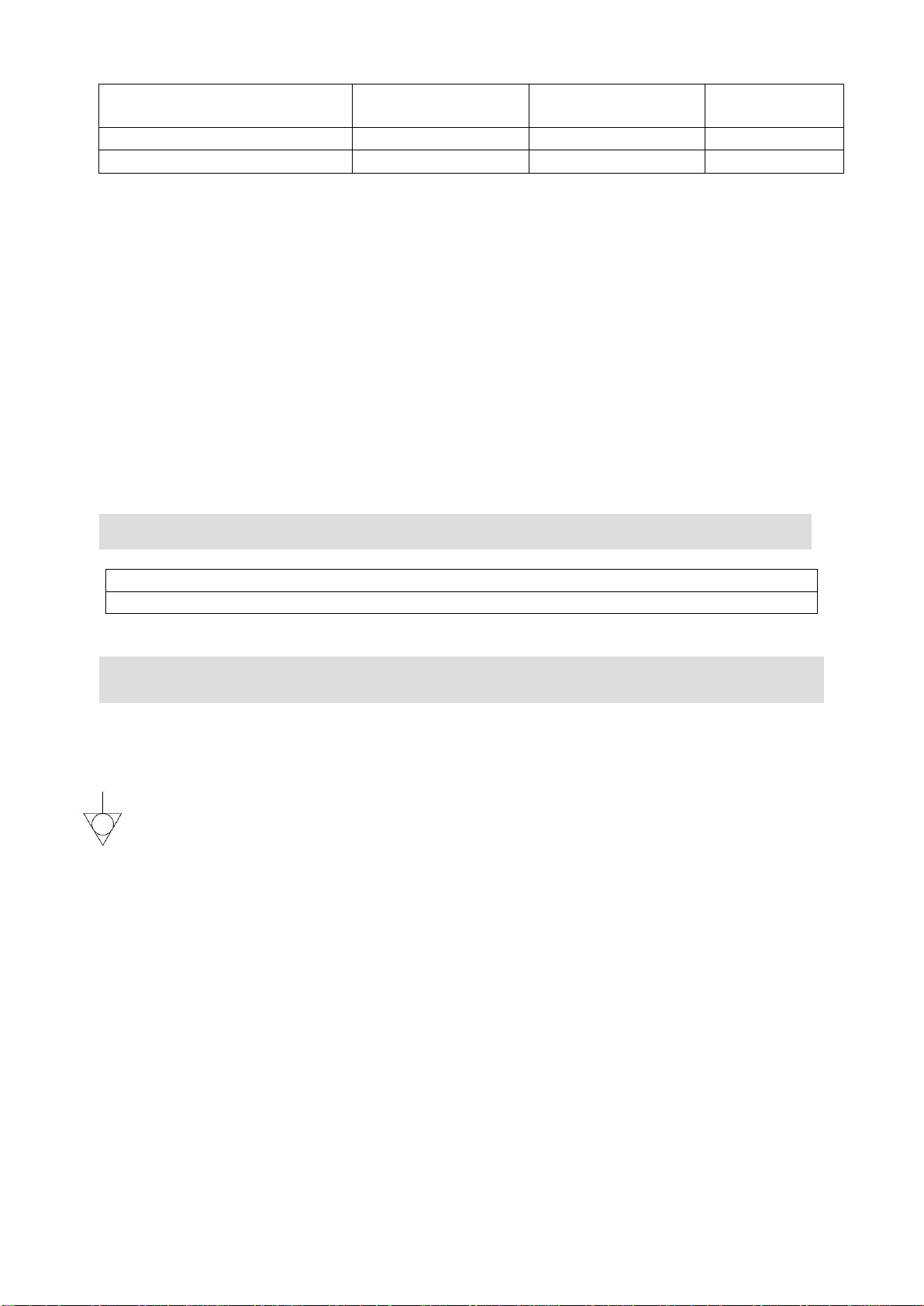
PHER01
PHER01/SPH
PHER02
Height (mm)
900
900
900
Width (mm)
900
900
600
Depth (mm)
800
800
800
Weight (kg)
137
137
Hob zones
6
6
4
Hob surface
6mm thick
ceramic glass
6mm thick
ceramic glass
6mm thick
ceramic glass
Electrical supply 3N~+E
400V 3ph 50-60Hz
Current (A)
L1 25
L2 25
L3 25
N/A
L1 17.4
L2 16.1
L3 16.1
Electrical supply 1 supply
1N~+E 230V 50-60Hz
Current (A)
N/A
56.5
50
Electrical supply 2
supplies1N~+E
230V 50-60Hz Current (A)
N/A
30.4
26.1
N/A
Hob zone power (kW)
6 x 1.85
6 x 1.85
4 x 1.85
This appliance must be installed, commissioned and serviced by a qualified person
in accordance with national and local regulations in force in the country of
installation.
Caution Symbol: Non-ionising electromagnetic radiation (magnetic field).
Warning Symbol: Dangerous voltage (live parts at a working voltage exceeding
250V).
If the supply cord is damaged, it must be replaced by the manufacturer, its service
agent or similarly qualified person.
Ensure that the plug/socket is accessible at all times.
Strip plastic coating and clean the appliance before use.
During operation parts may become hot - avoid accidental contact.
Disconnect this appliance before servicing, maintenance or cleaning.
If the ceramic glass surface is cracked, immediately disconnect the appliance
from the supply.
Do not stand on the unit. Surfaces are not to be used for storage.
The ceramic glass is very strong but do not slam pans down onto it and be careful
not to scrape pans along the surface.
IS707 ECN 4624 3
Page 4
Max combined weight of
pans on hobtop (kG)
50
50
50
Oven power (kW)
6.0
4.0
4.0
Total power (kW)
17.1
13.0
11.4
CHECK LIST OF ENCLOSURES
Warranty card
Instruction manual
INSTALLATION AND COMMISSIONING
PHER01/SPH WIRING
This unit is designed so it can be wired either with a single 63A plug and lead or two 32A
plug and leads. As supplied the unit is wired for a single 63A supply.
To wire it with two supplies, fit the extra cable gland supplied into the base. On the clear
mains terminal block remove the 4mm2 brown and blue cables linking the top and bottom
live and neutral connections, discard these two cables. Connect the two supply cables,
one to the top of the connector and one to the bottom connector. Do not crosslink the lives
or neutrals.
PHER02 single phase wiring requires fitting the 3 way yellow shorting link into the terminal
block across the three live connections
This appliance must be earthed.
An equipotential bonding terminal is provided to allow cross bonding with other
equipment.
If replacing the plug connect the terminals as follows:
Green and Yellow wire Earth E
Blue wire Neutral N
Brown wire Live L1
Black wire Live L2
Grey wire Live L3
Means of isolation with at least 3mm contact separation in all poles must be
incorporated into the fixed wiring of this appliance.
The fixed wiring insulation must be protected by insulated sleeving having a
temperature rating of at least 60oC.
Supply cords shall be oil resistant, sheathed flexible cable not lighter than ordinary
polychloroprene or equivalent elastomer sheathed cord (code 60245 IEC 57)
IS707 ECN 4624 4
Page 5
B
A
A
Do not block or restrict the inlet filters on the appliance. Restricted airflow will result
in reduced performance.
Keep means of electrical isolation accessible at all times.
A circuit breaker of type C, of suitable current rating should be fitted.
A Residual Current Device (RCD) of suitable current rating and min 30mA trip level
should be fitted. A short time delay AC-DC sensitive RCD is recommended.
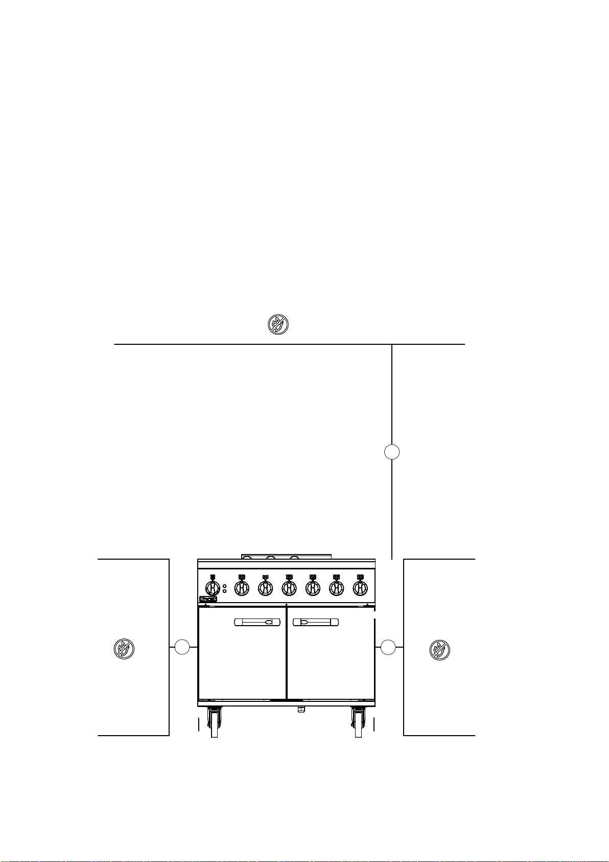
Install this appliance on a level surface ensuring all vents are unobstructed. Any
adjacent partitions, walls or furniture must be of non-combustible material. To avoid
heat damage to the induction modules do not place this appliance next to hot
appliances such as ranges and griddles without following the minimum distances
stated, A 100mm, B 1000mm – see Fig 1. Any heat damage through not following
this siting instruction will void the warranty of this appliance.
Fig 1
IS707 ECN 4624 5
Page 6

OPERATING INSTRUCTIONS
General Information
Only qualified or trained personnel should use this appliance.
The green neon illuminated indicates power to the appliance.
Hob
Rotate the control knob to the required power level setting.
After use, switch the hob zone off by means of the control. Do not rely on the pan
detectors.
Fans may continue to operate after controls are switched to zero. This is normal.
Do not place aluminium foil or plastic vessels on hot ceramic surfaces. Do not use
the surfaces for storage.
Metallic objects should not be placed within the cooking zones as they will get hot.
Take care when operating the appliance as rings, watches or similar objects could
get hot in close proximity to the hob surfaces.
Only use pans of the size and type recommended in the pan selection notes.
Users with heart pacemakers should consult with their doctor or the manufacturer of
the pacemaker.
Induction cooking and pan selection
Induction cooking produces heat directly in the base of the pan. The system
comprises a ceramic glass hob with an induction coil beneath it. The coil generates
an alternating magnetic field. When a pan with a magnetic base is placed on the
cooking zone, eddy currents are produced in the base of the pan leading to the
production of heat. The pan heats extremely quickly.
The quality of the cookware is essential to the efficiency of induction cooking. The
base of the pan needs to be flat with good heat distribution.
Suitable pans are made from cast iron, enamelled steel and stainless steel with a
magnetic base. Unsuitable pans are glass, earthenware, aluminium, copper and
non-magnetic stainless steel.
Operation of the pan detection system is dependent on the size of the pan and its
material. Power from the induction coil to the pan will vary and is dependent on
size and pan material.
It is normal for induction generators to make buzzing, whistling and clicking noises,
especially on lower power settings.
Locate the pan concentrically over the ceramic glass target ring. If the inner ring of
the ceramic glass is visible around the pan, the pan is too small.
IS707 ECN 4624 6
Page 7
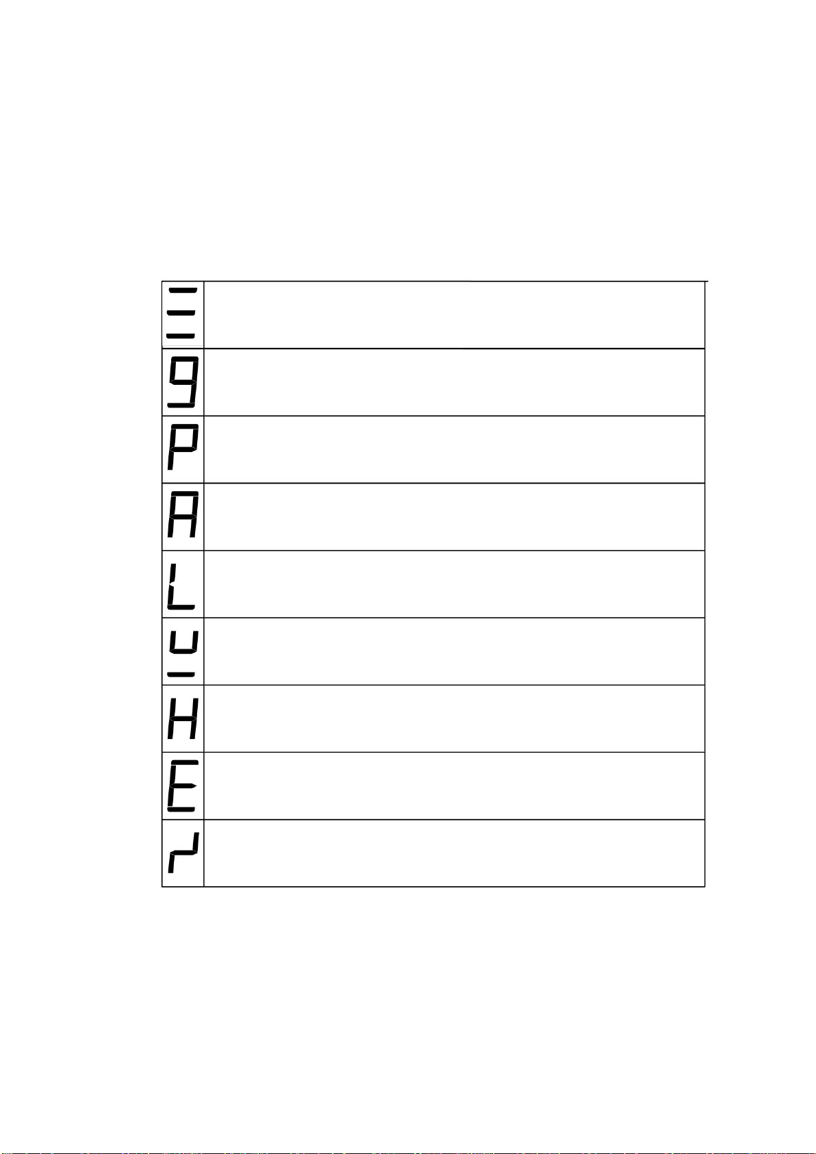
Melt, Keep warm, and Simmer functions
Power level setting (1-9)
Power boost function
Automatic heat up control
Control lock function
Pan detection (no pan present)
Residual heat display
Error codes - generator
Error – rotary control (lightning symbol)
Recommended pan base diameter – minimum of 120mm.
Nominal coil diameter – 180mm.
Maximum pan diameter is 250mm.
Hob control settings
Constantly variable power level settings are available via the rotary control knob.
There are a number on features available to you to enhance your appliances
productivity.
The following symbols are displayed through the glass
IS707 ECN 4624 7
Page 8
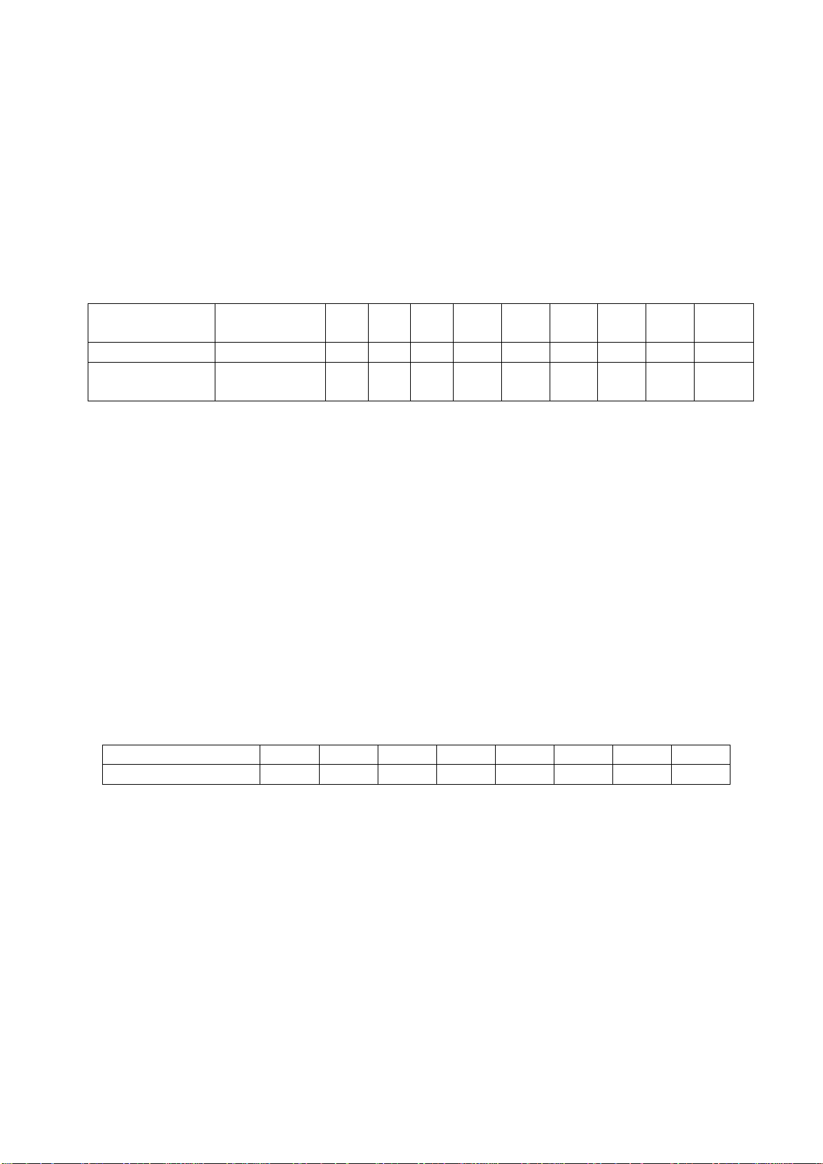
Melt, Keep warm, and Simmer functions
Power level
Low temp
hold
1 2 3 4 5 6 7 8 9
% of power
---
3%
5%
8%
12%
18%
28%
42%
64%
100%
Time limit
(mins)
120
520
402
318
260
212
170
139
113
90
Power level setting
1 2 3 4 5 6 7
8
Present time (secs)
40
72
120
176
256
432
120
192
The first three settings on the control knob are low temperature control functions.
One bar is melt to heat the pot to 45 °C, two bars is 70 °C and three bars is 94 °C.
These temperatures are approximate and depend on the pan quality and volume of
product.
Power level settings
9 power level settings are available. The table gives the percentage of maximum
power for each setting with the time limit for operation at that power.
Power boost function
Power boost is activated by turning the control clockwise from level 9. Only one coil
per front to back pair can be boosted at a time.
The power boost will run for a maximum of 10 minutes before reverting to level 9. It
may be boosted again, providing the system internal temperatures are satisfactory.
Automatic heat-up control (AHC)
When activated, the AHC will give maximum power (level 9) to a coil for a pre-set time
before reducing to a lower power level set by the control. To activate, the control is
turned anticlockwise from the ‘Off’ position briefly whilst the ‘A’ symbol illuminates: the
control is then turned clockwise to set the ‘final’ required power (1-8). The display
reverts to the ‘A’ symbol and the hob will run at maximum power for the time shown in
the table, before reducing power to the ‘final’ setting.
Control lock function
This function prevents unwanted operation of the hob. When the control lock is active,
the ‘L’ symbol is displayed. It operates on pairs of controls (Left, centre and right).It is
activated and de-activated by turning both control knobs anticlockwise to the control
lock position and held for approximately 5 seconds.
IS707 ECN 4624 8
Page 9
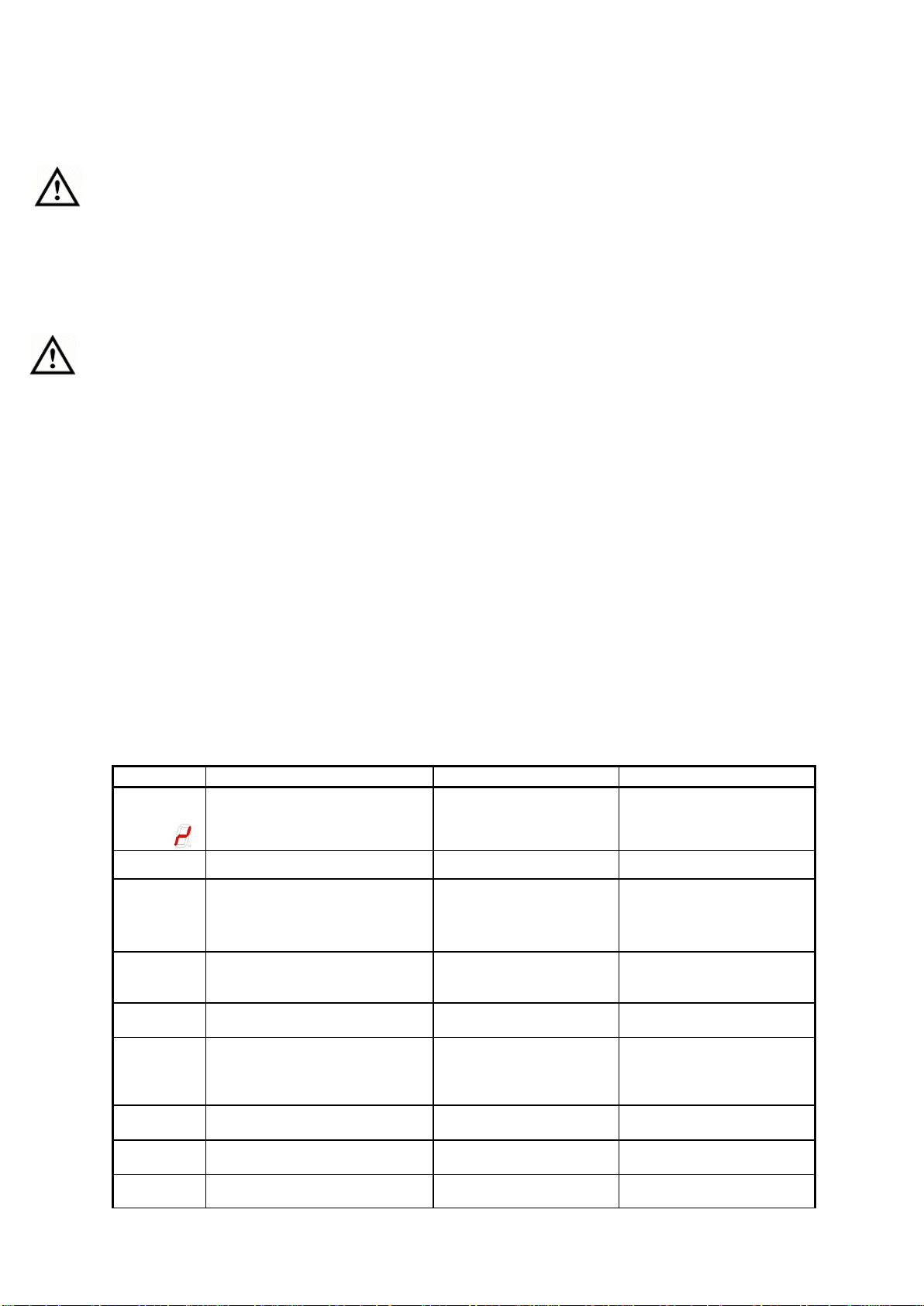
Pan detection function
Error code Description
Possible cause of error
Remedy
Er 03 and
continuous
tone or
continuous sensor activation; TC
turn off after 10 sec
Water or cookware on the
glass over the touch
control sensors
Clean the control surface,
remove objects on the
sensors
Er 20
Flash memory – TC error
µC- defective
Replace TC
Er 22
Button evaluation defective, UI
shuts off after 3.5-7.5 sec
Short or open circuit in the
area of the button sensor
Replace TC
Er 31
Incorrect configuration data or
deviation between generator and
TC
New configuration of the
induction generator
required
New configuration (Service
menu)
Er 36
NTC value defective on TC; UI
turns off
Short or open circuit of
NTC
Replace TC
Er 47
Communication error between
TC and induction
No or erroneous LIN
communication! (Slave
does not answer to
request of master)
Connection cable not
correctly plugged in or
defective.
U 400
Continuous tone
Power supply on inlet to high
Incorrect connection of the
cooktop
Correct power supply
connection
E / 2
Excess temperature of the
induction element
Overload of cooktop or
empty boiled cookware
Let system cool down.
E / A Error on the power board
Component failure
Replace power board
This prevents the coils being turned on without a pan being present, and also turns off
the coil as soon as a pan is removed. If the pan is of the wrong material for induction
equipment, the ‘no pan present’ symbol is displayed. After use, switch off the hob via
the control and do not rely on the pan detector.
Residual heat display
When the temperature of the hob top exceeds 60
o
C after removal of a pan, the ‘H’
symbol displays, indicating a hot surface. (Refer also to the error codes section).
Whilst the residual heat display is showing, leaving the appliance connected to the
power supply allows the cooling fans to continue to operate. When the ‘H’ symbol is
extinguished, switch off the power supply.
Error codes
There are numerous error codes identifying issues within the induction system. These are
primarily of use when reporting a fault to Lincat’s Service Department; however some
errors can be cleared by turning the control to the ‘Off’ position, unplugging the appliance
and then switching back on again.
A reduction in performance during cooking may be attributed to a blocked or restricted
air filter, a confined location with insufficient airflow or a failed cooling fan.
Error codes are shown on the display
This list shows the standard error codes. As standard general TC (thermocouple) errors
are “Er xx“and cooking element specific errors E/x are displayed.
IS707 ECN 4624 9
Page 10

IS707 ECN 4624 10
E / 6
Error on power board or supply
element
No power supply of the
power element or error on
power board
1.
check wiring
2.
check filter board
3.
replace power board
E / 8
Incorrect fan speed
Error on fan left or right
Air exhaust blocked,
e.g. by paper
Replace Defective fan
E / 9
Defective temperature sensor on
inductor
Replace inductor
Replace power board
Page 11

CLEANING
OVEN SETTING
Check the green ‘power on’ neon on the fascia panel is illuminated.
Set the control knob to the desired temperature in degrees Celsius. The
orange light will illuminate indicating that power is being supplied to the
elements.
The orange light will go out when the oven has achieved the set temperature.
Periodically the orange light will illuminate to indicate that the oven
temperature has fallen and the elements are turned on to top up the
temperature.
SHUT DOWN
To shut down the appliance rotate all control knobs clockwise to the OFF position.
After operation, some parts of the appliance will remain hot for a period of time;
care should be taken to avoid risk of burns.
OPENING OF THE OVEN DOOR
Care must be taken to avoid injury when opening the oven door when the oven is
being used as hot air will rapidly escape.
Your product has a manufacturer’s warranty. This requires you maintain and care
for your product and follow maintenance instructions. If you fail to maintain your unit
or damage components, Lincat may charge you for a warranty repair. Please check
the website for terms and conditions.
Isolate from the power supply and allow to cool.
Do not use a water jet or steam cleaner, and do not immerse this appliance.
Clean all panels with warm water and mild detergent do not use abrasive or chlorine
based cleaners. Do not wet electrical components. Dry with a soft cloth.
Clean the ceramic glass regularly, avoiding abrasive sponges or scouring agents
and harsh chemicals like oven sprays. Remove dirt and food with a scraper or
Vileda Ceran cleaning sponge.
If plastic, aluminium foil or sugary food has dropped onto hot ceramic glass,
scrape off immediately. If these substances melt they can damage the
surface.
Check the air filter regularly – they are washable if contaminated. Ensure they are
fully dry before refitting.
IS 688 ECN 4178 Page 11 of 13
Page 12
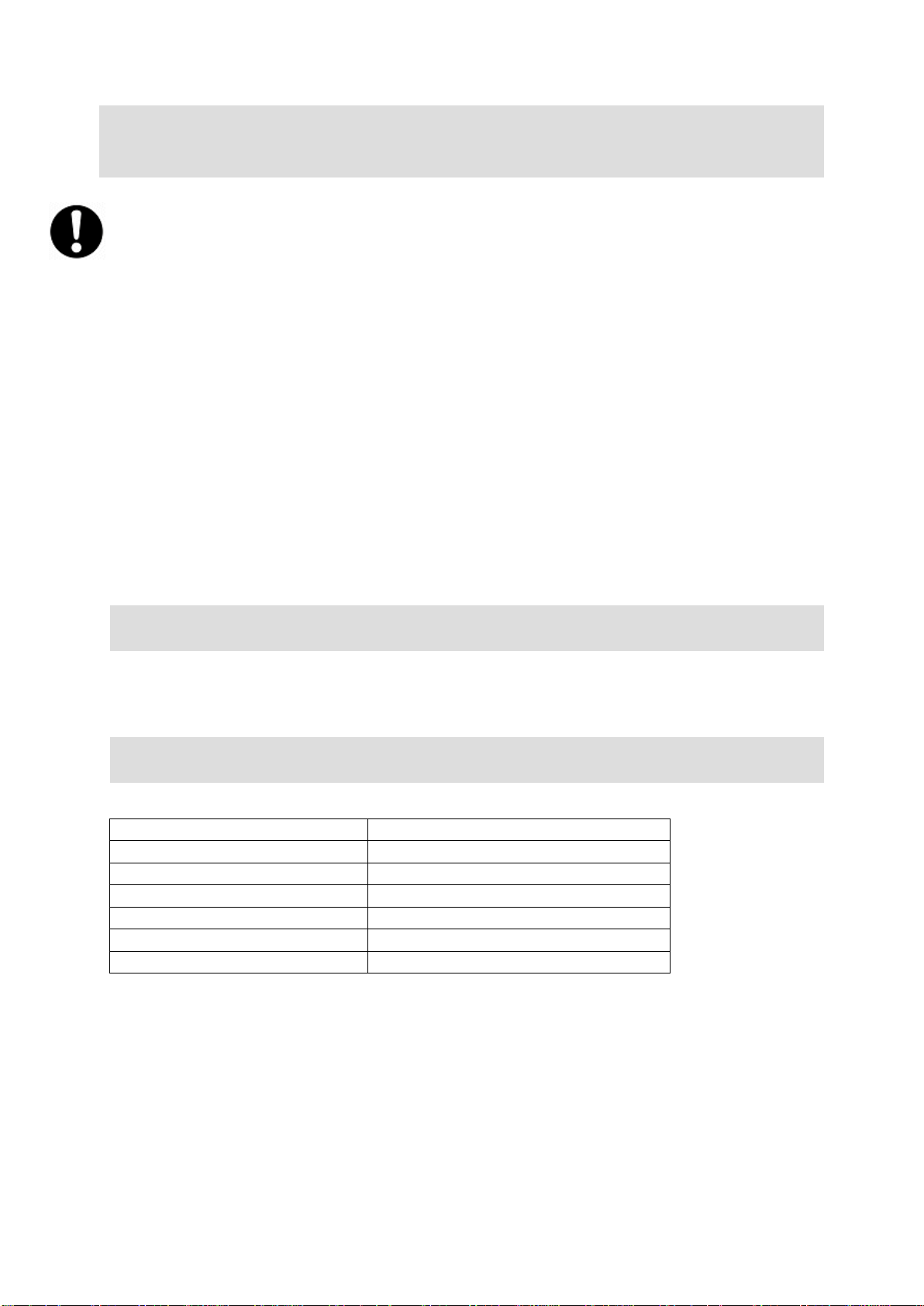
SERVICING, MAINTENANCE AND
COMPONENT REPLACEMENT
Part Number
Description
FI36
Filter pad
KN506
Hob control knob
KN523
Oven control knob
CA143
Front lockable swivel castor
CA145
Rear swivel castor
SE25
Oven door seal (3metres required)
FAULT FINDING
SPARE PARTS LIST
Removing the air filter
Removing and cleaning the air filter will ensure an adequate supply of cool air and
restore performance. Disconnect from the power supply and allow the appliance to
cool. The filters are located on the base of the unit.
At the back of the unit on the hob top is a metal cover. Lift this vertically to remove
the housing, filter holder and filter. Remove the filter from housing. This filter can be
cleaned in a dishwasher.
Do not operate the appliance without a filter being fitted, otherwise dirt and grease
could be drawn into the electronics, impairing safe operation and invalidating the
warranty.
All other servicing, maintenance and component replacement on this appliance
should be carried out by one of our recommended service engineers.
Please refer to the Service Help Desk number on the final page of this manual.
Fault codes are listed in the Operating section above.
IS 688 ECN 4178 Page 12 of 13
Page 13

Product code
All available on serial plate
Type number
Serial number
SERVICE INFORMATION
For help with the installation, maintenance and use of your Lincat equipment,
please contact our service department:
UK: 01522 875520
For non-UK customers, please contact your local Lincat dealer
All service work, other than routine cleaning should be carried out by one of our
authorised service agents. We cannot accept responsibility for work carried out by
other persons.
To ensure your service enquiry is handled as efficiently as possible, please tell us:
Brief details of the problem
Lincat reserve the right to carry out any work under warranty, given reasonable
access to the appliance, during normal working hours, Monday to Friday, 08:30 to
17:00.
GUARANTEE
This unit carries a comprehensive UK mainland 2 year warranty. The guarantee is
in addition to, and does not diminish your statutory or legal rights.
The guarantee does not cover:
Accidental damage, misuse or use not in accordance with the manufacturer’s
instructions
Consumable items (such as filters, glass, bulbs, slot toaster elements and door
seals.)
Damage due to incorrect installation, modification, unauthorised service work or
damage due to scale, food debris build-up, etc.
The manufacturer disclaims any liability for incidental, or consequential damages.
Attendance is based on reasonable access to the appliance to allow the authorised
technician to carry out the warranty work.
Service calls to equipment under warranty will be carried out in accordance with the
conditions of sale. Unless otherwise specified, a maximum of 15 minutes of
administrative time, not spent directly carrying out servicing work, is provided for
within the warranty. Any requirement for staff attending the call to spend greater time
than 15 minutes due to administrative requirements, such as on health and safety risk
assessments, will be chargeable at the prevailing rate.
IS 688 ECN 4178 Page 13 of 13
 Loading...