

Page 1
Please make a note of your product details for
future use:
Date Purchased:_________________________
Model Number:__________________________
Serial Number:__________________________
Dealer:_________________________________
_______________________________________
Installation, Operating and Servicing
Instructions
Opus 800 Electric Direct Cook Chargrills
OE8413, OE8414.
IS 728 ECN 4470 Page 1 of 10
Page 2
CONTENTS
Important Information
2
Warnings and Precautions
3
Technical Data
3
Checklist of Enclosures
3
Installation and Commissioning
4-5
Operating Instructions
5-6
Cleaning
7
Servicing, Maintenance and Component Replacement
7-8
Fault Finding
9
Spare Parts List
9
Accessories
9
Service Information and Guarantee
10
IMPORTANT INFORMATION
Read these instructions carefully before using this product, paying particular
attention to all sections that carry warning symbols, caution symbols and notices.
Ensure that these are understood at all times.
WARNING!
This symbol is used whenever there is a risk of personal injury.
CAUTION!
This symbol is used whenever there is a risk of damaging your Lincat product.
NOTE:
This symbol is used to provide additional information, hints and tips.
KEEP THIS MANUAL FOR FUTURE REFERENCE
IS 728 ECN 4470 Page 2 of 10
Page 3
WARNINGS AND PRECAUTIONS
TECHNICAL DATA
OE8413
OE8414
Height (mm)
400
400
Width (mm)
600
900
Depth (mm)
800
800
Weight (kg)
58.1
78.5
Power Rating (kW)
8.4
13.44
Supply 3N~+E
400V 50-60Hz
Current (A)
L1 11
L2 11
L3 15
L1 15
L2 22
L3 22
CHECK LIST OF ENCLOSURES
Warranty card
Instructions manual
Splashguard
Removable inner tank
Slip stop washers x 2
Scraper
This appliance must be installed, commissioned and serviced by a qualified person
in accordance with national and local regulations in force in the country of
installation.
If the supply cord is damaged, it must be replaced by the manufacturer, its service
agent or similarly qualified person.
Ensure that the plug/socket is accessible at all times.
Strip plastic coating and clean the appliance before use.
During operation parts may become hot - avoid accidental contact.
Disconnect this appliance before servicing, maintenance or cleaning.
IS 728 ECN 4470 Page 3 of 10
Page 4
INSTALLATION AND COMMISSIONING
This appliance must be earthed.
An equipotential bonding terminal is provided to allow cross bonding with other
equipment.
If replacing the plug connect the terminals as follows:
Green and Yellow wire Earth E
Blue wire Neutral N
Brown wire Live L
Fig 1
IS 728 ECN 4470 Page 4 of 10
Page 5
Means of isolation with at least 3mm contact separation in all poles must be
OPERATING INSTRUCTIONS
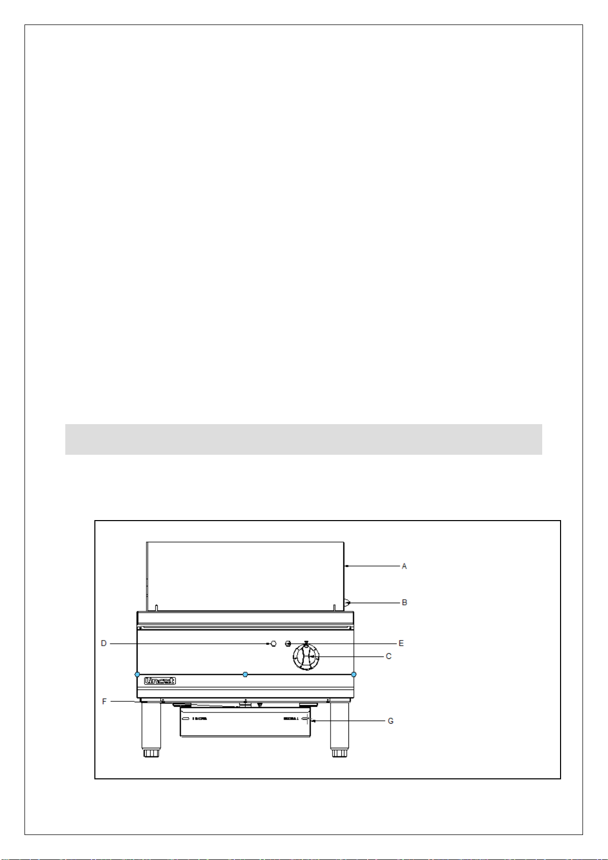
A Splashback
B Element lock pin
C Control knob
D Green neon
E Amber neon
F Drain tube
G Fat collection drawer
incorporated into the fixed wiring of this appliance.
The fixed wiring insulation must be protected by insulated sleeving having a
temperature rating of at least 60 Deg C.
Supply cords shall be oil resistant, sheathed flexible cable not lighter than ordinary
polychloroprene or equivalent elastomer sheathed cord (code 60245 IEC 57)
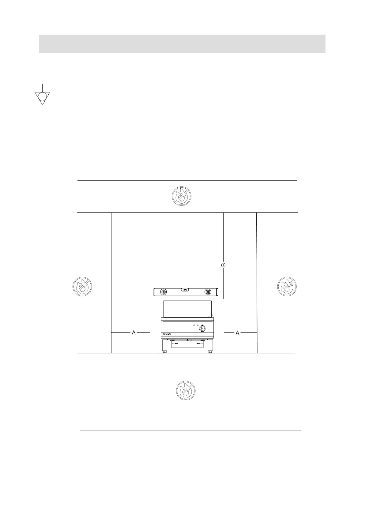
Install this appliance on a level surface ensuring all vents are unobstructed. Any
partitions, walls or furniture must be of non-combustible material. Minimum
distances A 100mm B 1000mm – see Fig 1.
Ensure there is a space of at least (1000 mm) between the working surface and any
ceiling.
Install this appliance beneath an extraction canopy.
Connection of the supply cable is behind the access panel on the rear of the
appliance. Remove the access panel and fit a suitable cable through the cable
gland to the terminal block.
Anti-slip washers are provided to create a slip free pocket for the front feet, so
preventing movement during operation. Ensure the work surface is structurally safe
before installing the washers.
Only qualified or trained personnel should use this appliance.
This appliance should not be operated unattended.
IS 728 ECN 4470 Page 5 of 10
Fig 2
Page 6

Operating and controls
Switch on the power supply at the isolating switch – the green neon will illuminate.
OE8413 – The branding plates create one large cooking zone.
OE8414 – The branding plates create one large cooking zone, divided into two
equal areas, each independently controlled.
Turn the control knobs to the desired setting. On settings 1-5 the elements will
cycle to maintain the temperature. On setting 6 the elements remain on constantly.
Note: Position 6 should only be used for cleaning due to the extreme
temperatures at this position.
The amber neon will illuminate when the heating element is on.
Do not leave the chargrill running on a high setting for prolonged periods when not
cooking. If it is considered desirable to maintain element heat under these
conditions, it is important to turn down the control to a low setting. This can
contribute to energy saving.
Ensure the fat collection drawer or suitable receptacle is place directly below the
drain hole to capture any grease or food debris.
To turn the appliance off after cooking, rotate all control knobs to the ‘Off’ position,
and turn off the electrical supply.
To raise the elements remove the splashguard. Lift from the front close to the
element support bar using the tool provided. Lift the element to the vertical position.
Ensure that the element securing pins lock them in place.
Ensure the removable tank is fitted before lowering. To lower elements, holding the
element vertical pull the element securing pin horizontally. With the pin released,
slowly lower element and release the pin. Place the element back down into its
horizontal position.
Note: the removable tank supports are different heights the lower support
should be at the rear of the unit.
Ensure elements are cold before raising
IS 728 ECN 4470 Page 6 of 10
Page 7

CLEANING
SERVICING, MAINTENANCE AND
COMPONENT REPLACEMENT
Do not use a water jet or steam cleaner, and do not immerse this appliance.
Clean all panels with warm water and mild detergent, do not use abrasive materials.
Dry with a soft cloth.
Turn the control to maximum position and allow to run for approximately 15 minutes.
Due to the extreme temperature of the elements at this position, most food debris
should carbonize and fall off the elements.
Scrape off any debris that may be left using the element tool provided.
Before cleaning by hand ensure the unit is completely turned off and the elements
are cold.
Elements can be cleaned with a cloth and hot soapy water.
The splashguard is removable for cleaning.
The inner element support tank is removable for cleaning. To access the removable
tank raise the element to the vertical position.
Remove any food debris from the tank and pour a quantity of warm soapy water into
the tank to assist with draining.
Debris will collect behind the removable tank. Ensure any debris is also removed on
a daily basis and the outer tank is clean.
Do not use abrasive materials or any products containing chlorine or hydrochloric
acid. Dry with a soft cloth.
.
Lower the elements and replace all removable parts correctly.
Your Lincat product has a manufacturer’s warranty. This requires you to maintain
and care for your product and follow maintenance instructions. If you fail to maintain
your unit or damage components Lincat may charge you for a warranty repair.
Please check the website for terms and conditions.
All servicing, maintenance and component replacement on this appliance should be
carried out by one of our recommended service engineers.
IS 728 ECN 4470 Page 7 of 10
Page 8

Routine Service
Carry out a general check of the installation paying particular attention to the
following:
The suitability of the supply cable.
The installation of isolation points for electricity and water.
The correct operation of all components.
Non leakage of the tank
Component replacement
Element
Remove the screws securing the element to the lifting box.
Disconnect the electrical terminals, marking each to assist with reassembly.
Reverse the above procedure to reassemble the appliance.
Cut out switch in lifting box
Remove the screws securing the element to the lifting box.
Move the element forward to gain access to the cut out switch.
Remove the cables and transfer to the new switch.
Remove the old switch and reassemble by reversing the above sequence.
Neon
Remove the screws securing the facia to the base panel and hobtop. Free the facia
by pulling towards you from the bottom.
Remove the cables from the neon and free the neon by unscrewing the retaining
nut.
Fit new neon and reverse the above procedure to reassemble.
Energy regulator
Remove the facia as detailed for neon replacement above.
Disconnect cables from the energy regulator terminals and fit to new regulator.
Unscrew the old regulator and refit the new regulator by reversal of the above
procedure.
IS 728 ECN 4470 Page 8 of 10
Page 9
Contactor
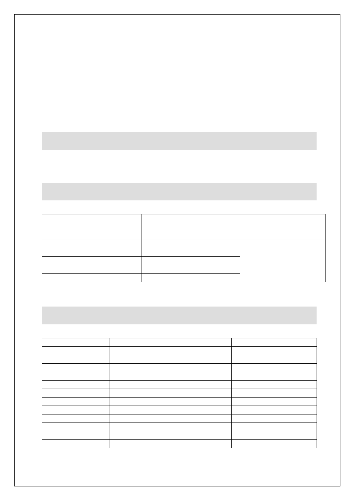
Part Number
Description
Used on
EL333
Element
OE8413
EL334
Element
OE8414
CO264
Contactor
OE8413, OE8414
EN10
Energy regulator
KN511
Control knob
NE46
Green neon
NE47
Amber neon
Part Number
Description
Used on
OA8989
Holding shelf
OE8413
OA8990
Holding shelf
OE8414
OA8972
Pedestal with doors
OE8413
OA8973
Pedestal with doors
OE8414
OA8972/C
Pedestal with doors with castors
OE8413
OA8973/C
Pedestal with doors with castors
OE8414
OA8917
Floor stand
OE8413
OA8914
Floor stand
OE8414
OA8917/C
Floor stand with castors
OE8413
OA8914/C
Floor stand with castors
OE8414
OA9002
Condiment holder
OE8413
OA9003
Condiment holder
OE8414
FAULT FINDING
SPARE PARTS LIST
ACCESSORIES
Remove the rear access panel to gain access to the contactor.
Unclip the contactor from the bracket.
Transfer the cables one at a time to the new contactor using a thin screwdriver to
release the wiring clamps.
Refitting is the reversal of removal.
Please refer to the Service Help Desk number on the final page of this manual.
IS 728 ECN 4470 Page 9 of 10
Page 10
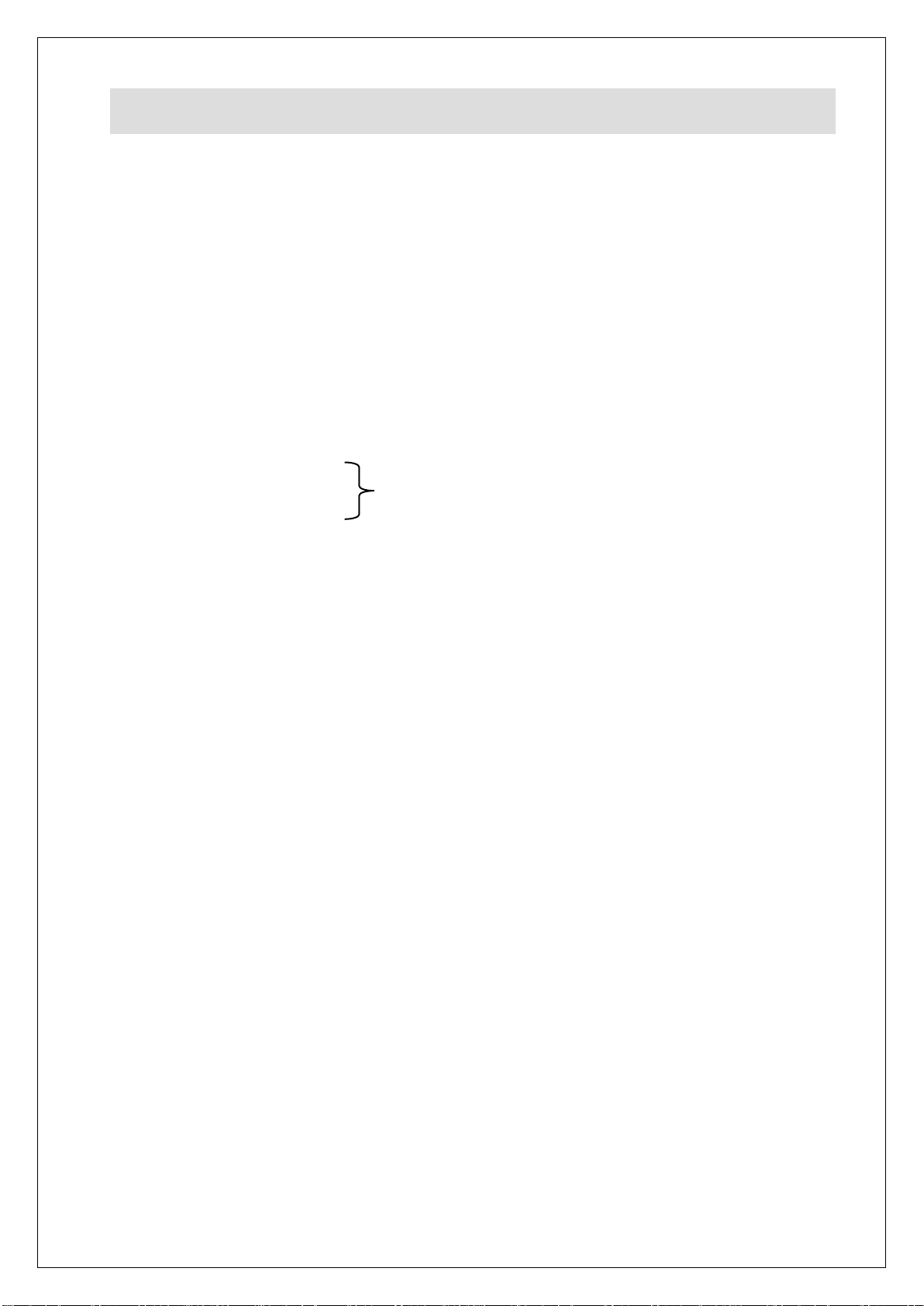
Product code
All available on serial plate
Type number
Serial number
SERVICE INFORMATION
For help with the installation, maintenance and use of your Lincat equipment,
please contact our service department:
UK: 01522 875520
For non-UK customers, please contact your local Lincat dealer
All service work, other than routine cleaning should be carried out by one of our
authorised service agents. We cannot accept responsibility for work carried out by
other persons.
To ensure your service enquiry is handled as efficiently as possible, please tell us:
Brief details of the problem
Lincat reserve the right to carry out any work under warranty, given reasonable
access to the appliance, during normal working hours, Monday to Friday, 08:30 to
17:00.
GUARANTEE
This unit carries a comprehensive UK mainland 2 year warranty. The guarantee is
in addition to, and does not diminish your statutory or legal rights.
The guarantee does not cover:
Accidental damage, misuse or use not in accordance with the manufacturer’s
instructions
Consumable items (such as filters, glass, bulbs, slot toaster elements and door
seals.)
Damage due to incorrect installation, modification, unauthorised service work or
damage due to scale, food debris build-up, etc.
The manufacturer disclaims any liability for incidental, or consequential damages.
Attendance is based on reasonable access to the appliance to allow the authorised
technician to carry out the warranty work.
Service calls to equipment under warranty will be carried out in accordance with the
conditions of sale. Unless otherwise specified, a maximum of 15 minutes of
administrative time, not spent directly carrying out servicing work, is provided for
within the warranty. Any requirement for staff attending the call to spend greater time
than 15 minutes due to administrative requirements, such as on health and safety risk
assessments, will be chargeable at the prevailing rate
IS 728 ECN 4470 Page 10 of 10
 Loading...