

Page 1

Please make a note of your product details for
future use:
Date Purchased:_________________________
Model Number:__________________________
Serial Number:__________________________
Dealer:_________________________________
_______________________________________
Installation, Operating, Servicing &
Conversion Instructions
Opus 800 Gas Fryers
OG8110, OG8110/OP, OG8111, OG8111/OP,
OG8111/OP2, OG8106, OG8106/OP, OG8107,
OG8107/OP
IS 679 ECN 4913 Page 1 of 24
Page 2
CONTENTS
Important Information
2
Warnings and Precautions
3
Technical Data
4
Checklist of Enclosures
4
Installation and Commissioning
5-8
Operating Instructions
9-10
Cleaning
11
Servicing, Maintenance and Component Replacement
12-14
Conversion
Fault Finding
15-16
17-20
Spare Parts List
21
Accessories
21
Service Information and Guarantee
Notes
22
23-24
IMPORTANT INFORMATION
Read these instructions carefully before using this product, paying particular
attention to all sections that carry warning symbols, caution symbols and notices.
Ensure that these are understood at all times.
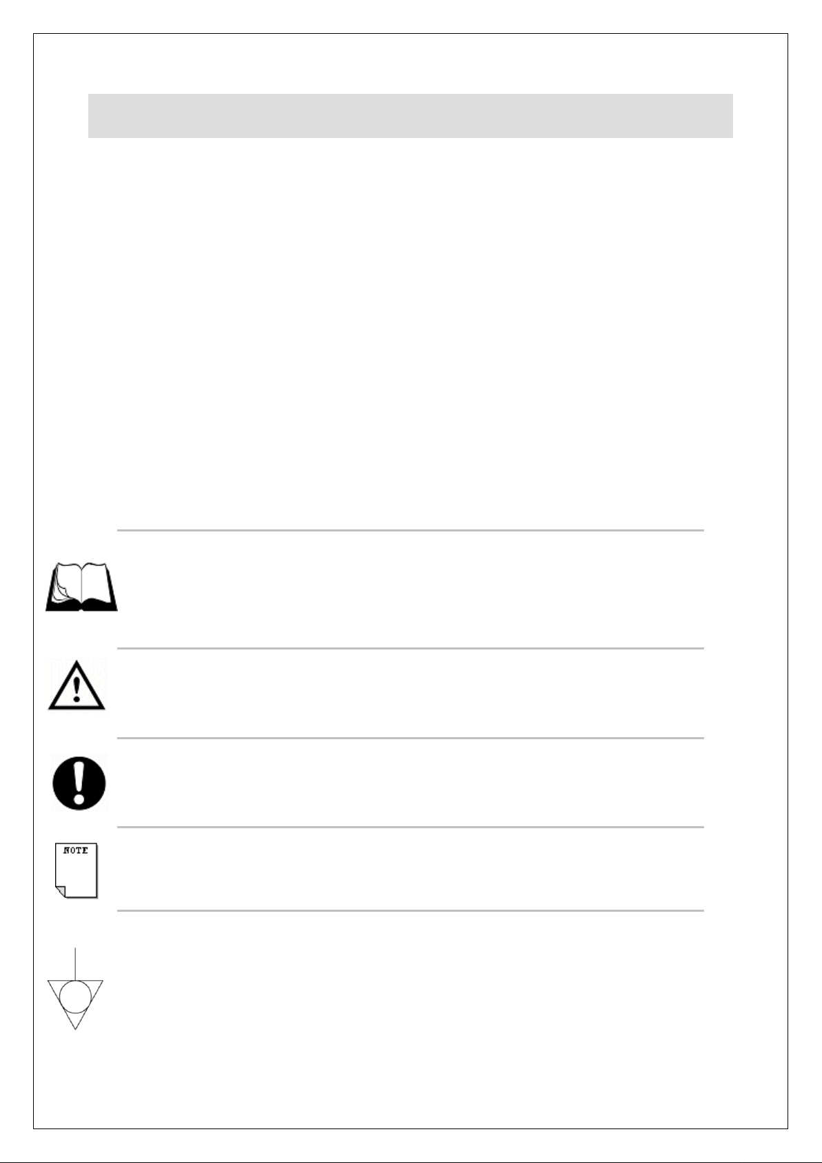
WARNING!
This symbol is used whenever there is a risk of personal injury.
CAUTION!
This symbol is used whenever there is a risk of damaging your Lincat product.
NOTE:
This symbol is used to provide additional information, hints and tips.
EQUIPOTENTIALITY
This equipment is provided with an equipotential bonding terminal to allow earth
cross-bonding with other equipment.
KEEP THIS MANUAL FOR FUTURE REFERENCE
IS 679 ECN 4913 Page 2 of 24
Page 3

WARNINGS AND PRECAUTIONS
Only qualified or trained personnel should use this appliance.
Parts protected by the manufacturer shall not be adjusted by the user.
Do not leave the appliance unattended whilst operating.
Do not operate with dust cover in place.
Do not obstruct or block the flue.
If the supply cord is damaged, it must be replaced by the manufacturer, its service agent or
similarly qualified persons in order to avoid a hazard.
All equipment must be earthed to prevent shock.
Disconnect the unit from the electricity supply before cleaning, servicing or undertaking any
maintenance.
If this appliance is fitted with castors, use caution at all times when manipulating or moving,
and lock castors when appliance is in position.
During operation parts may become hot - avoid accidental contact.
Install a suitable fire extinguisher and fire blanket within reach of the appliance.
Do not use flammable solvents and cleaning aids.
Strip plastic coating and clean the appliance before use.
This unit is designed to be used with oils and fats in a liquid form.
Oils and fats that become solid at lower temperatures must be liquefied prior to
dispensing into the fryer tank.
On units with filtration the oil or fat used must also be liquid prior to operating the pump.
Old oil has a reduced flashpoint and is more prone to surge boiling.
Do not operate without oil in the tank.
Do not over heat the oil.
Care must be taken when replenishing the oil during service.
Oil should be filtered regularly.
This instruction includes both filling from empty and topping up during use.
IS 679 ECN 4913 Page 3 of 24
Page 4
TECHNICAL DATA
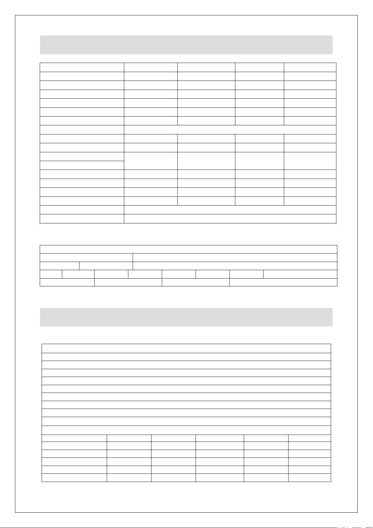
OG8110
OG8111
OG8106
OG8107
Height (mm)
900
900
900
900
Width (mm)
400
600
400
600
Depth (mm)
800
800
800
800
Weight (kg)
70
102
92.6
105
Oil capacity (l)
14
28
16
25
Maximum frying weight
1 x 1.5kg
2 x 1.5kg
2 x 1.0kg
2 x 1.5kg
Gas inlet connection
½ G
Gas pressure – Natural I2H
13
13
14
14
Gas pressure – Propane I3P
22
20
25
25
Heat input (Gross) – Natural I2H
16kW
(54,600 Btu)
32kW
(109,200 Btu)
23kW
(78,500 Btu)
30kW
(102,400 Btu)
Heat input (Gross) – Propane I3P
Injector size (mm) – Natural I2H
2.2 (220)
2.2 (220)
2.7 (270)
3.0 (300)
Injector size (mm) – Propane I3P
1.55 (155)
1.55 (155)
1.75 (175)
2.0 (200)
Gas rate – Natural I2H
1.52 m3h
-1
3.05 m3h-1
2.19 m3h
-1
2.86 m3h-1
Gas rate – Propane I3P
1.14 kg h
-1
2.29 kg h-1
1.64 kg h
-1
2.14 kg h-1
Supply pressure – Natural I2H
20
Supply pressure – Propane I3P
37
Connections
Connection
Location
Size
½ Rc (1/2" BSP)
LOWER REAR
Volts
230
Phase
Single
Amps
4.9
Hz
50-60
Connection
3 Pin Plug
Location
RH Lower Rear
CHECK LIST OF ENCLOSURES
All Units:
Warranty card
Instructions manual
Baskets – OG8110 x 1, OG8111 x 2, OG8106 x 1, OG8107 x 2
Batter plate
Drain Bucket
Legs / Castors
Leg spanner (with leg kit only)
Stabilising kit
Filtration Units only:
OG8110/OP
OG8111/OP
OG8111/OP2
OG8106/OP
OG8107/OP
Filter Bag
1 1 2 1 1
Filter Bag Frame
1 1 2 1 1
Stainless Steel Filter
1 1 2 1 1
Oil Return Lance
1 1 2 1 1
Oil Return Hose
1 1 2 1 1
These appliances are designated Category I and category II (II
2H3P
)
IS 679 ECN 4913 Page 4 of 24
Page 5

INSTALLATION AND COMMISSIONING
This appliance must be installed, commissioned, serviced and converted by a
qualified person in accordance with national and local regulations in force in the
country of installation.
Site this appliance beneath an extraction canopy for the removal of combustion
products.
When making the gas connection, fit an isolating cock into the supply line close to
the appliance for emergency shutdown or servicing purposes.
Installation must include sufficient ventilation to prevent the occurrence of
unacceptable concentrations of substances harmful to health in the room of
installation. There must be a minimum free area of 4.5cm2 per kW of total heat
input.
Allow for a sufficient flow of fresh air for complete gas combustion.
Do not connect directly to any flue, ducting or mechanical extraction system.
The gas supply hose or tubing shall comply with national requirements in force and
shall be periodically examined and replaced as necessary. If flexible hose is used,
secure the appliance to the wall with a chain.
A clear space of at least 100mm must be left to the rear of the appliance and
600mm to the front to allow for safe operation.
Install this appliance on a level surface ensuring all vents are unobstructed. Any
partitions, walls or furniture must be of non-combustible material.
Gas supply and connection
Check that the gas supply corresponds to that specified on the data plate.
Connection is at the rear of the unit via a ½ G female thread. The gas supply tubing
or hose shall comply with the national requirements in force and shall be
periodically examined and replaced as necessary.
An isolating cock should be fitted into the supply line close to the unit for emergency
shutdown or servicing purposes.
Fitting the Stabilising Kit (Fig 1)
The stabilising kit must be fitted to prevent accidental toppling of the appliance and
to ensure a safe working environment.
IS 679 ECN 4913 Page 5 of 24
Page 6
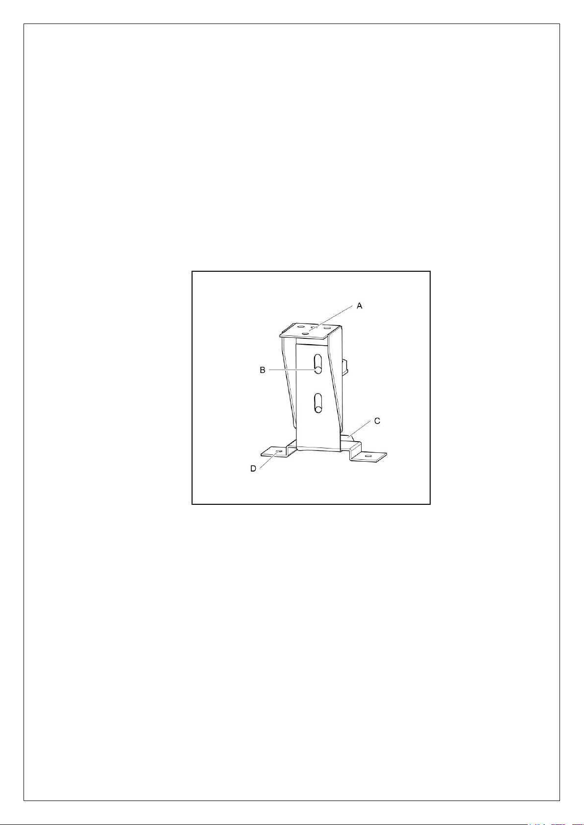
Fit the adjustable stabiliser centrally to the underside of the front cross member of
the appliance (A) using the M5 x 16 hex screws and shake proof washers provided.
Ensure the tongue of the bracket is facing rearward and adjusted to sit just off the
floor(C).
Position the appliance in the intended place. Place the floor plate (D) on the floor
so that it fits over the tongue of the stabiliser.
Mark locating hole positions of the floor plate. Drill out holes and fit supplied
rawlplugs.
Screw the floor plate in position using 12g screws.
Adjust height position (B) of stabiliser tongue if necessary.
Fig 1
On the filtration units the following must be observed:
If the supply cable is damaged it should be replaced by Lincat Ltd or other suitably
qualified persons, in order to avoid a hazard.
For safety regulations the plug or means of disconnection must always be
accessible.
This unit must be earthed.
This unit is supplied with a 10 amp plug. If replacing the plug, connect the terminals
as follows:
Green and yellow wire Earth E
Blue wire Neutral N
Brown wire Live L
IS 679 ECN 4913 Page 6 of 24
Page 7

Commissioning
Ensure that the oil drain valve is closed and clean the tank with a warm, mild
detergent solution. Rinse the tank and dry.
Run a small quantity of oil across the base of the tank and allow it to drain to
remove all traces of water and to provide the base of the tank with a coating of oil.
Close the drain valve. Fill the tank with oil to the low level marker on the batter
plate.
Pressure setting (Fig 2)
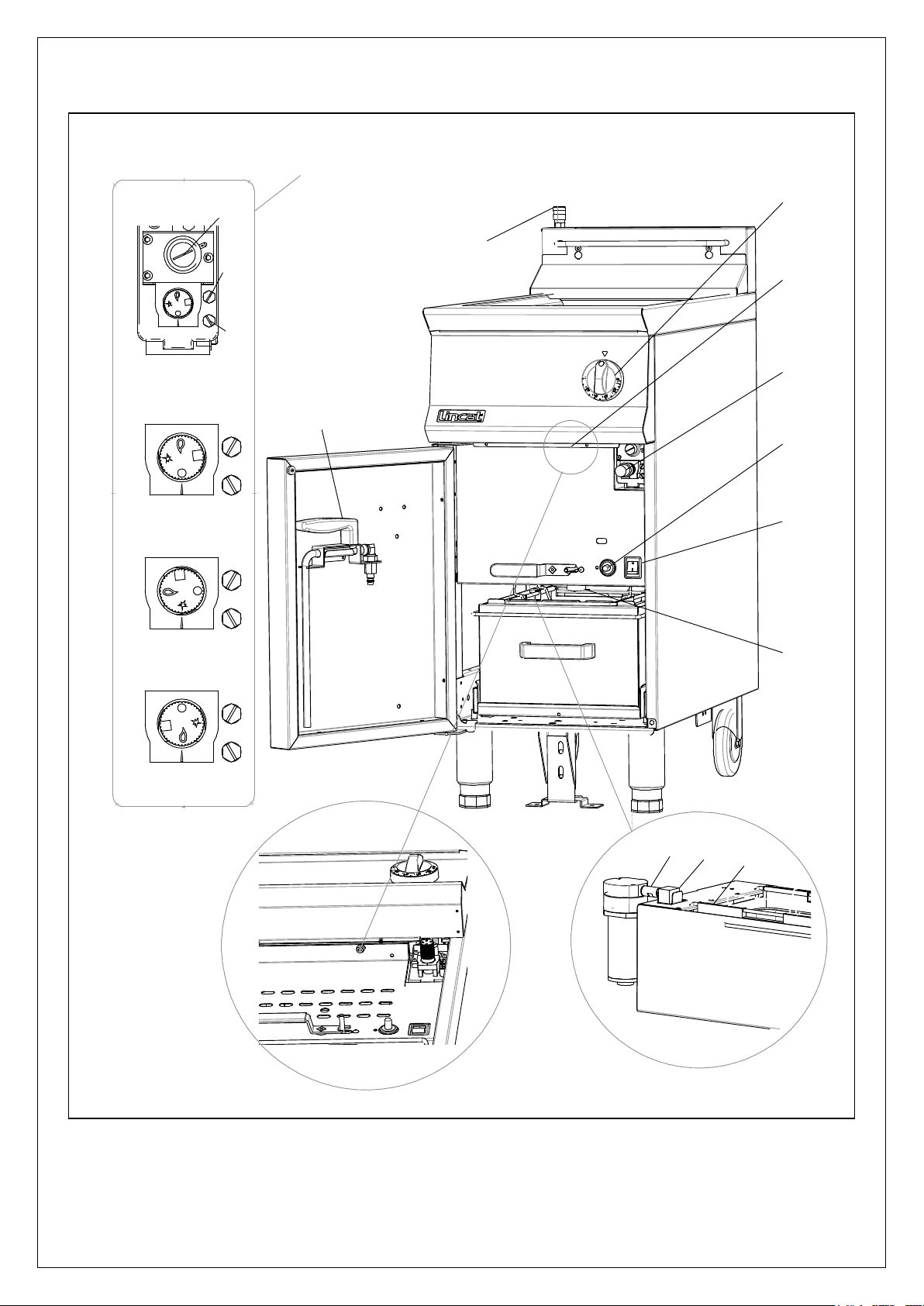
Use the test point provided on the gas control to check the inlet pressure (I) and to
set the appropriate burner pressure (J).
Adjustment is made via the valves on board governor, situated centrally on the
valve (K). Remove the governor cap and turn the screw clockwise to increase
outlet pressure, anticlockwise to reduce it.
After setting, ensure the governor cap is properly secured.
With main burner lit, adjust to the appropriate burner pressure.
Note: An external regulator should be fitted to the appliance only if the inlet
pressure exceeds 50mbar.
Operational check
Light the appliance several times as per instructions, checking for correct and
smooth ignition.
Operate the thermostat knob several times and observe that the burner ignites
smoothly and without delay.
Set the thermostat to 190ºC and allow the oil to heat up. Check the oil temperature
25mm below the surface in the geometric centre of the tank.
Ensure that the end user understands how to light, operate, shutdown and clean the
appliance, and is aware of the position of the gas isolating cock.
IS 679 ECN 4913 Page 7 of 24
Page 8
A
B
C
D
E
F
G
H
I
J
K
Valve Detail
L
M
N
R
Q
P
Fig 2
IS 679 ECN 4913 Page 8 of 24
Page 9

OPERATING INSTRUCTIONS
This appliance is for professional use and must be operated by qualified or
trained personnel only.
This unit is intended to be used to produce deep fried products only.
General advice
For maximum efficiency, do not overload the baskets with product as it will result in
reduced recovery times, uneven cooking and increased risk of surge boiling.
Always drain product before frying. Ensure water is never introduced into the oil as
this will cause splashing and possible overflow from the tank.
Filling with oil
Remove and store the dust cover.
Check the drain valve is closed and fill with good quality oil to the low level mark on
the batter plate. (Maintain oil at the upper level mark during use).
Lighting sequence (Fig 2)
Ensure the thermostat dial is turned to the ‘Off’ position (E).
Open the door to gain access to the gas control valve (A).
Rotate the valve knob to the Pilot position (M) Press and hold.
Ignite the pilot by pressing the piezo igniter (C). Operate until a pilot flame can be
seen through the viewing port.
After ignition, hold the knob depressed for 20-30 seconds to establish the pilot
flame. Release the knob and turn anticlockwise to the main burner position (N).
To operate the main burner, turn the thermostat control knob (E) to the required
temperature.
Note: The gas control valve is fitted with a step opening ignition device which
reaches full rate after approximately 10 seconds. There is also a start interlock
device which prevents the appliance from re-igniting until the flame supervision
device has interrupted the gas flow. After this stage it is possible to re-ignite the
appliance.
IS 679 ECN 4913 Page 9 of 24
Page 10

Standby
To turn the appliance to standby, turn the thermostat control knob (E) to the ‘Off’
position.
Shutdown
To turn the appliance off completely, turn the thermostat control knob to the ‘Off’
position, then slightly depress the gas control valve knob (A) and rotate to the ‘Off’
position (L). Turn off at the mains cock.
Note: Should the safety cut out thermostat operate during use, the appliance will
shut down. To re-light the appliance, allow the oil to cool and reset the thermostat
by pressing the red button (B) located underneath the control panel.
Filtration models only:
Ensure that the filtration bag and frame (P) and the suction pipe (Q) correctly fitted
and secured in the oil bucket and that the bucket is engaged in the pump
connection (R).
Drain the oil and close the drain valve as previously explained.
Securely connect the oil return lance (H) into the connector (G).
Operate the pump run switch (F) until the oil has returned to the fryer tank then turn
off the pump run switch.
Remove (H), clean and place back in the door bracket.
IS 679 ECN 4913 Page 10 of 24
Page 11
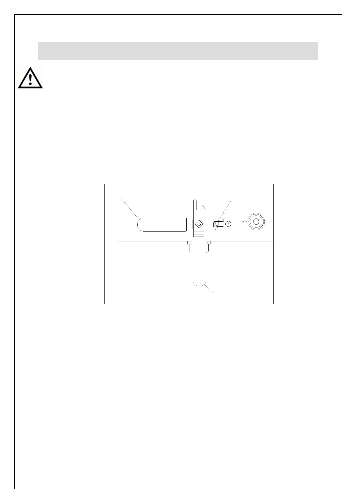
CLEANING
A
B
C
Do not use a water jet or steam cleaner, and do not immerse this appliance.
Turn the appliance off and isolate from the gas supply.
Ensure the drain container is in place.
To open the tap slide the latch (A) to the right and rotate the handle from position
(B) to position (C) (Fig 3).
Once drained, close the tap to position (B) and the latch (A) will engage to prevent
accidental opening.
Fig 3
Wash the tank using a warm detergent solution.
With the drain tap open, clean using a suitable drain brush.
Dry all parts thoroughly and then flush tank, drain valve and elbow through with a
small quantity of cooking oil to remove residual water.
Clean all surface panels with warm water and mild detergent do not use abrasive
materials. Dry with a soft cloth.
The baskets, batter plates, drain bucket and filter mesh (Filtration units only) can be
cleaned in a dishwasher.
IS 679 ECN 4913 Page 11 of 24
Page 12

SERVICING, MAINTENANCE AND
COMPONENT REPLACEMENT
All servicing, maintenance and component replacement on this appliance should be
carried out by one of our recommended service engineers.
Routine Service
Check the installation, specifically the hose type and condition, the installation of a
safety chain and the installation of a separate isolation valve.
Check the burner operation, observing flame picture. Look for evidence of debris or
damage. Remove burner and clean or replace as necessary. Check burner
pressure as detailed in Commissioning section. Adjust if necessary.
Check injectors and clean or replace if necessary. Use nylon bristled brush and not
reamers or wire which may affect orifice size.
Clean and check operation of the pilot assembly – check and adjust if required the
alignment of the electrode and thermocouple.
Ensure the flue is clear.
Carry out a gas soundness check.
Component replacement
Before any of the following, ensure appliance is disconnected from supply.
Remove the lower cover to carry out the following work:
Burner injectors
Access from behind the manifold and remove and replace using a 12mm spanner.
Burners
Undo the 12mm fitting at the manifold inlet.
Undo the screws holding the manifold to the burners. Remove the manifold.
Undo the screws from the burner flange and remove the burners.
Reverse the above to reassemble.
IS 679 ECN 4913 Page 12 of 24
Page 13

Pilot assembly
Remove deflector plate below the pilot assembly.
Undo the pilot feed pipe from the pilot body taking care not to lose the injector.
Undo the electrode, thermopile and thermocouple.
Remove igniter cable from electrode.
Undo the two screws holding the pilot body to the chassis.
Reverse the above to reassemble.
Thermocouple
Remove the control knob. Open the doors and undo the screws beneath the facia
panel. Undo the screws holding the thermostat. Remove the facia panel.
Undo the nut holding thermocouple to control valve.
Undo nut securing thermocouple to pilot body and pull down.
Replace the thermocouple and reverse procedure to reassemble.
Thermopile
Remove the facia panel as detailed above.
Undo the screws holding the thermopile connections to the control valve.
Release the retaining nut and draw the thermopile clear of the pilot body.
Replace thermopile and reverse procedure to reassemble.
Control thermostat
Drain the tank. Undo the screw holding the cover within the tank and slide off.
Undo the nuts and release the bracket to ease removal of the thermostat bulb.
Remove the control panel as detailed earlier. Disconnect the two wires from the
control thermostat.
Release the gland nut and withdraw the thermostat bulb, there will be resistance
due to the packing behind the gland nut having been compacted.
Withdraw the thermostat, replace and reassemble by reversing the procedure.
IS 679 ECN 4913 Page 13 of 24
Page 14

Safety thermostat
Drain the tank. Undo the screw holding the cover within the tank and slide off.
Undo the nuts and release the bracket to ease removal of the thermostat bulb.
Remove the control panel as detailed earlier.
Release the gland nut and withdraw the thermostat bulb, there will be resistance
due to the packing behind the gland nut having been compacted.
Disconnect interrupter cables and remove the nut holding the thermostat to the
chassis.
Reverse the above to reassemble, ensuring bulb and capillary are not damaged
when installing.
Control valve
Disconnect the gas supply, burner feed and pilot pipes from the valve.
Disconnect thermocouple, thermopile and thermostat connections.
Remove the screws securing the valve to the chassis.
Remove the brass fittings from the old valve and reuse them on the new valve – NB
valves are not supplied with brass fittings.
Reverse the above to reassemble. Check for soundness.
IS 679 ECN 4913 Page 14 of 24
Page 15
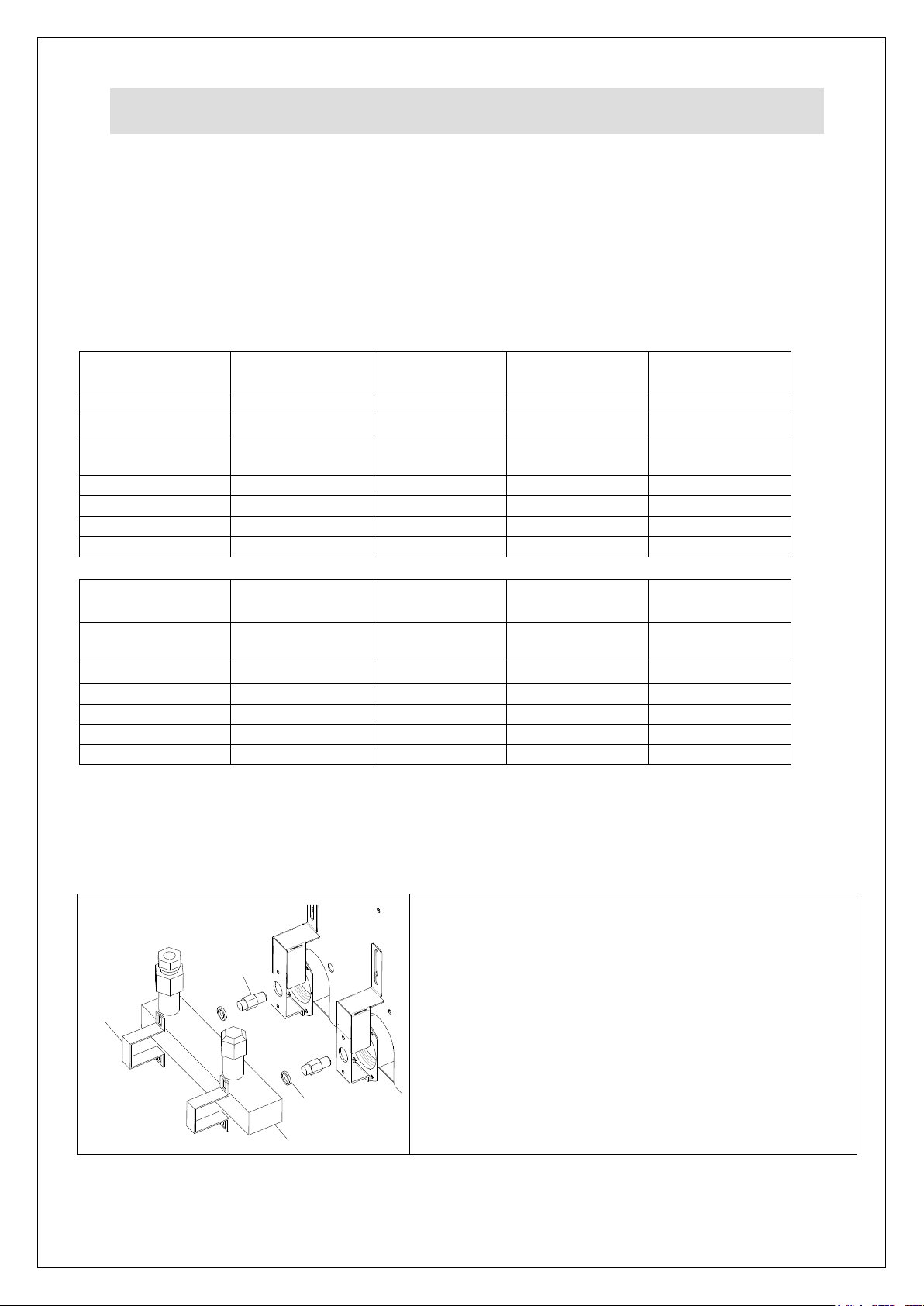
Convert to
Model:
OG8110/N
CKN67
OG8110/P
CKP67
OG8111/N
CKN68
OG8111/P
CKP68
Burner Jets
2 x JE88 (220)
2 x JE89 (155)
4 x JE88 (220)
4 x JE89 (155)
3/8 BSP Washer
2 x WA13
2 x WA13
4 x WA13
4 x WA13
Cross-light Jet
1 x JE31 (26N)
1 x JE32
(LP16)
2 x JE31 (26N)
2 x JE32 (LP16)
Pilot Jet
1 x JE86 (51)
1 x JE87 (35)
2 x JE86 (51)
2 x JE87 (35)
Serial Plate
Nat Gas G20
Propane G31
Nat Gas G20
Propane G31
Gas Ident Label
“NATURAL”
“PROPANE”
“NATURAL”
“PROPANE”
Regulator Spring
1 x SP65
1 x SP65
Convert to
Model:
OG8106/N
CKN69
OG8106/P
CKP69
OG8107/N
CKN70
OG8107/P
CKP70
Burner Jets
2 x JE277 (270)
2 x JE278
(175)
2 x JE97 (300)
2 x JE98 (200)
3/8 BSP Washer
2 x WA13
2 x WA13
2 x WA13
2 x WA13
Pilot Jet
1 x JE86 (51)
1 x JE87 (35)
1 x JE86 (51)
1 x JE87 (35)
Serial Plate
Nat Gas G20
Propane G31
Nat Gas G20
Propane G31
Gas Ident Label
“NATURAL”
“PROPANE”
“NATURAL”
“PROPANE”
Regulator Spring
1 x SP65
1 x SP65
A
B
D
C
Undo the screws securing the cover plate and remove.
Undo the screws holding the brackets ‘A’ and remove.
Withdraw the manifold ‘B’ from the burners to allow
removal of the injectors ‘D’.
Replace injectors and fit new copper washers ‘C’
Reassemble in reverse order.
CONVERSION
This appliance cannot be converted by the user.
For a conversion kits contact the manufacturer whose details may be found in the
service section of this manual.
This conversion must be carried out by a Gas Safe Certified engineer
Conversion of Gas Type
Burner Injector replacement
IS 679 ECN 4913 Page 15 of 24
Page 16
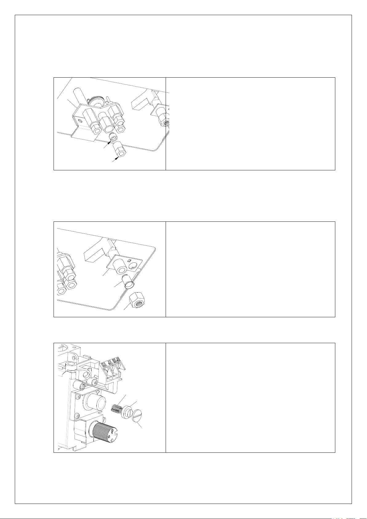
E
F
G
Remove the cover plate as above. Undo the
screws supporting the splash guard and remove
to gain access to the Pilot assembly ‘E’.
Undo the pilot feed pipe nut ‘G’ and pull the pipe
from the body. Remove and replace with the
appropriate injector and reassemble in reverse
order.
H
I
J
Remove the cover plate as above. Undo the
screws supporting the splash guard and remove
to gain access to the Cross-light assembly ‘H’.
Undo the feed pipe nut ‘J’ and pull the pipe from
the body. Remove and replace with the
appropriate injector and reassemble in reverse
order.
M
L
K
Unscrew the cap ‘K’ and the adjuster ‘L’.
Carefully replace the spring ‘M’ with the supplied
spring ‘SP65’.
Reassemble in reverse order taking care to
ensure correct engagement with the spring and
the internal diaphragm.
Pilot Injector replacement
Cross-Light Injector replacement (OG8110 & OG8111 models only).
Propane spring replacement
IS 679 ECN 4913 Page 16 of 24
Page 17
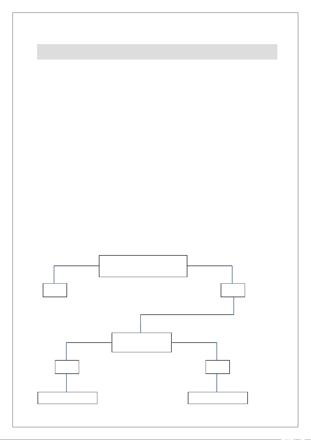
FAULT FINDING
Is there a short in the High
Tension lead
Yes
Has electrode
insulator fractured
No
Yes
No
Replace electrode
Replace piezo igniter
Explanation of the control system
The gas circuit of this appliance is controlled by two millivolt systems.
The first consists of an interrupted thermocouple, the pilot burner and the gas
control. Heat from the pilot flame acting on the thermocouple generates a 15-20mV
electrical potential. This operates the first solenoid on the gas control, allowing gas
to the pilot. The safety thermostat is included in this system which operates via the
interrupted thermocouple. The first solenoid acts as the safety device which shuts
down in the event of a thermocouple failure or if the safety thermostat goes open
circuit.
The second millivolt system consists of a thermopile acting through the gas control
via the control thermostat. Heat from the pilot flame acting on the thermopile
generates a 500-700mV electrical potential. This millivolt system connected to the
gas control operates the secondary solenoid, allowing gas to the main burner. The
system is interrupted by the control thermostat as it cycles, thereby opening and
closing the gas supply to the burners.
The following flowcharts are designed to give assistance on the most probable
source of failure.
Piezo igniter not sparking
IS 679 ECN 4913 Page 17 of 24
Page 18
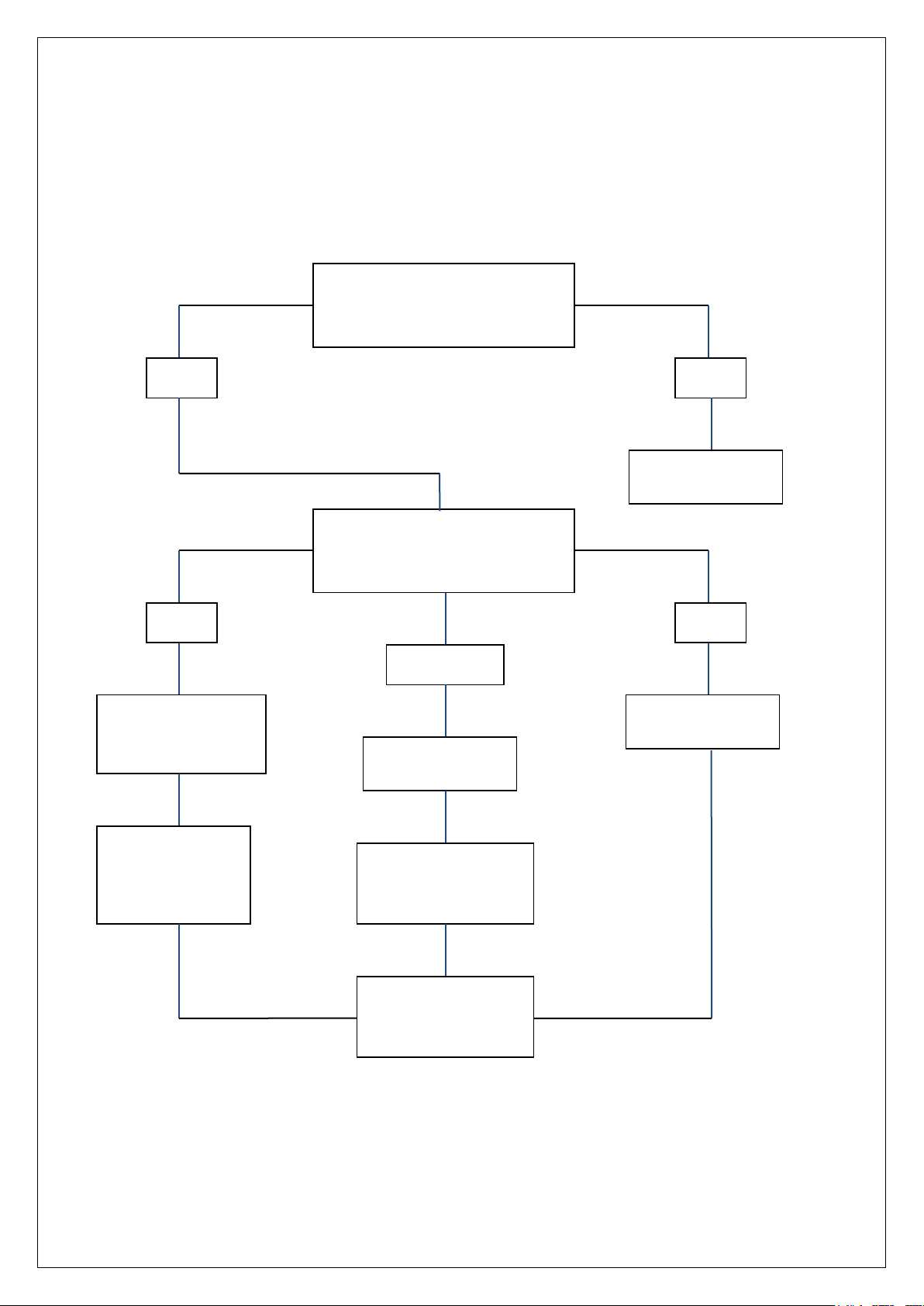
Are the thermocouple/interrupter
connections secure
Yes
No
Tighten
connections
Is there gas at the pilot when
holding control knob in the pilot
position
Yes
No
Check supply
Check safety
thermostat for open
circuit
Very little
Check supply
Check
thermocouple
voltage (minimum
15mV)
Check pilot injector
for blockage and
clean if necessary
If all the above are
correct the control
valve may be faulty
Pilot burner will not light or stay lit
IS 679 ECN 4913 Page 18 of 24
Page 19
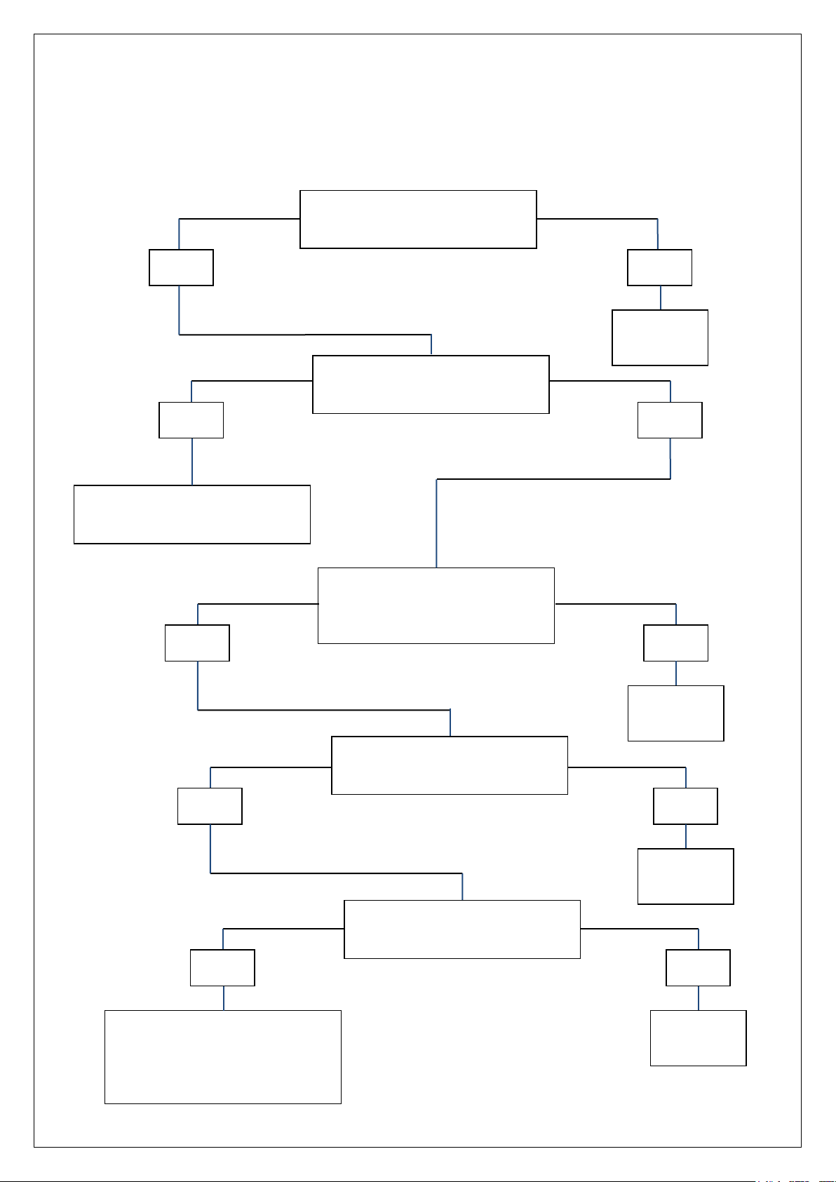
Is the gas control set to the ‘On’
position
Yes
No
Set to ‘On’
and retry
Has the safety thermostat
operated
Yes
No
Reset safety thermostat and retry
Are the thermopile connections
correct and tight
Yes
No
Correct and
retry
Is there continuity through the
thermostat
No
Replace
thermostat
Yes
Is the pilot flame impinging on the
thermopile
No
Rectify and
retry
Yes
Check output from thermopile
(320mV) minimum required whilst
pilot is operating. If reading is
lower, replace thermopile
Main burner will not light
IS 679 ECN 4913 Page 19 of 24
Page 20
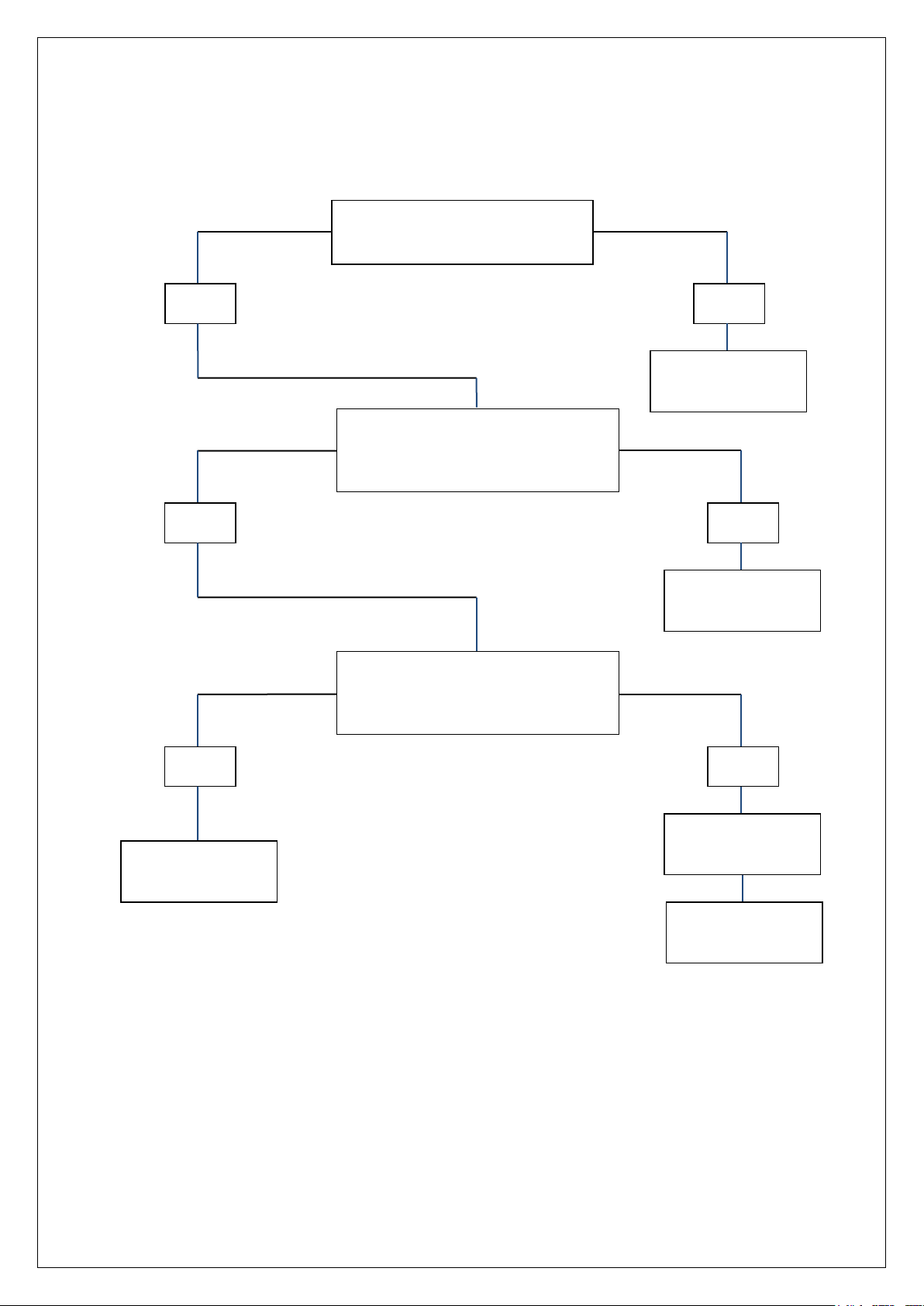
Is the oil temperature over 200
Deg C
Yes
No
Replace safety
thermostat
Does the control thermostat operate
on temperature rise when set point is
low (100 Deg C)
No
Replace control
thermostat
Yes
Are the connections correct on the
gas control
No
Correct
connections
Manually reset
safety thermostat
Yes
Replace safety
thermostat
Safety thermostat operates
IS 679 ECN 4913 Page 20 of 24
Page 21
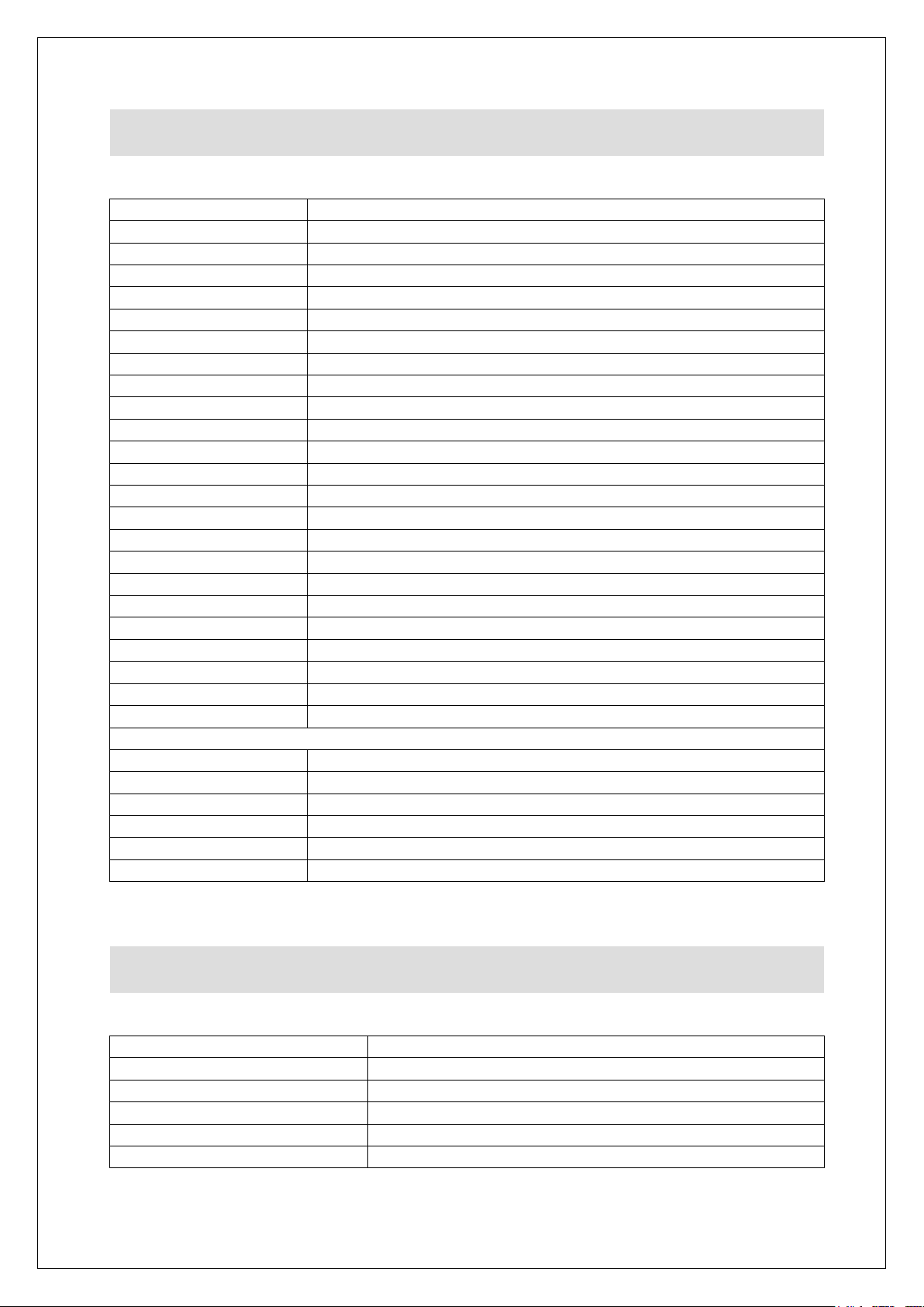
Part Number
Description
BA165
Basket OG8110, OG8111
BA82
Basket OG8106, OG8107
BA159
Half Basket OG8106, OG8107
BS27
Basket support OG8106
BS26 – BS28
Basket support OG8110, OG8111
BS28
Basket support OG8107
BU248
Burner OG8110, OG8111
BU250
Burner OG8106, OG8107
FZ401101
Drain valve
IG15
Igniter electrode
IG35
Piezo igniter
IG37
Igniter earth lead
IG39
Ignition lead
IN08
Interrupter Block
KN501
Control knob
LE37
Leg
PI08
Pilot body
TC51
Thermocouple
TC20
Thermopile
TH59B
Encapsulated Control thermostat
TH129B
Encapsulated Safety thermostat
VA20
Control valve
Filtration Models only:
FZ214013
Oil Pump
FZ214026
AC-DC Transformer
FZ101142
Filter Bag Support OG8110, OG8111
FZ101143
Filter Bag Support OG8106, OG8107
FZ101158
Filter Bag OG8110, OG8111
FZ101159
Filter Bag OG8106, OG8107
Part Number
Description
OA8954
Splashguard
OA8955
Splashguard
SPARE PARTS LIST
ACCESSORIES
IS 679 ECN 4913 Page 21 of 24
Page 22

Product code
All available on serial plate
Type number
Serial number
SERVICE INFORMATION
For help with the installation, maintenance and use of your Lincat equipment,
please contact our service department:
For non-UK customers, please contact your local Lincat dealer
All service work, other than routine cleaning MUST be carried out by qualified
personnel and a record kept of any remedial actions taken and at least cover the
requirements of the service schedule of this document. We cannot accept
responsibility for work carried out by other persons.
To ensure your service enquiry is handled as efficiently as possible, please tell us:
Brief details of the problem
Lincat reserve the right to carry out any work under warranty, given reasonable
access to the appliance, during normal working hours, Monday to Friday, 08:30 to
17:00.
DECLARATION
All Lincat products capable of burning gaseous fuels, satisfy the requirements of the
Gas Appliance Regulations 2016/426.
UK: 01522 875520
GUARANTEE
This unit carries a comprehensive UK mainland warranty. The guarantee is in
addition to, and does not diminish your statutory or legal rights. Contact Lincat for
terms and conditions
The guarantee does not cover:
Accidental damage, misuse or use not in accordance with the manufacturer’s
instructions
Consumable items (such as filters, glass, bulbs, slot toaster elements and
door seals.)
Damage due to incorrect installation, modification, unauthorised service work
or damage due to scale, food debris build-up, etc.
The manufacturer disclaims any liability for incidental, or consequential damages.
Attendance is based on reasonable access to the appliance to allow the authorised
personnel to carry out the warranty work.
Service calls to equipment under warranty will be carried out in accordance with the
conditions of sale. Unless otherwise specified, a maximum of 15 minutes of
administrative time, not spent directly carrying out servicing work, is provided for
within the warranty. Any requirement for staff attending the call to spend more than
15 minutes due to administrative requirements, such as on health and safety risk
assessments, will be chargeable at the prevailing rate.
IS 679 ECN 4913 Page 22 of 24
Page 23

Notes
IS 679 ECN 4913 Page 23 of 24
Page 24

Notes
IS 679 ECN 4913 Page 24 of 24
 Loading...