

Page 1

OG7402 Gas Chargrill
USER INSTRUCTIONS
Please read the following carefully before using this appliance.
Warnings and Precautions
Please ensure that all commissioning checks and initial start-up procedures have taken place.
Please ensure that the installation engineer has instructed the user how to light, safely operate
and shutdown the appliance, and that the user has been made aware of the position and
operation of the gas isolating cock for use in the event of an emergency.
This manual should be kept in a safe and accessible place for future reference.
This appliance is designed for professional use and must only be operated by qualified
personnel.
It is mandatory that all appliances are installed, commissioned and serviced by a qualified
and competent person as defined by the regulations in force in the country of installation.
Failure to comply will invalidate the warranty.
Please ensure that the appliance is serviced regularly by a competent and registered catering
equipment engineer.
Whilst in operation, parts of the appliance may become hot. Please take care to avoid
accidental burns. The flue outlet must not be blocked and must be kept clear at all times.
IS141 ECN 2740 1
Page 2
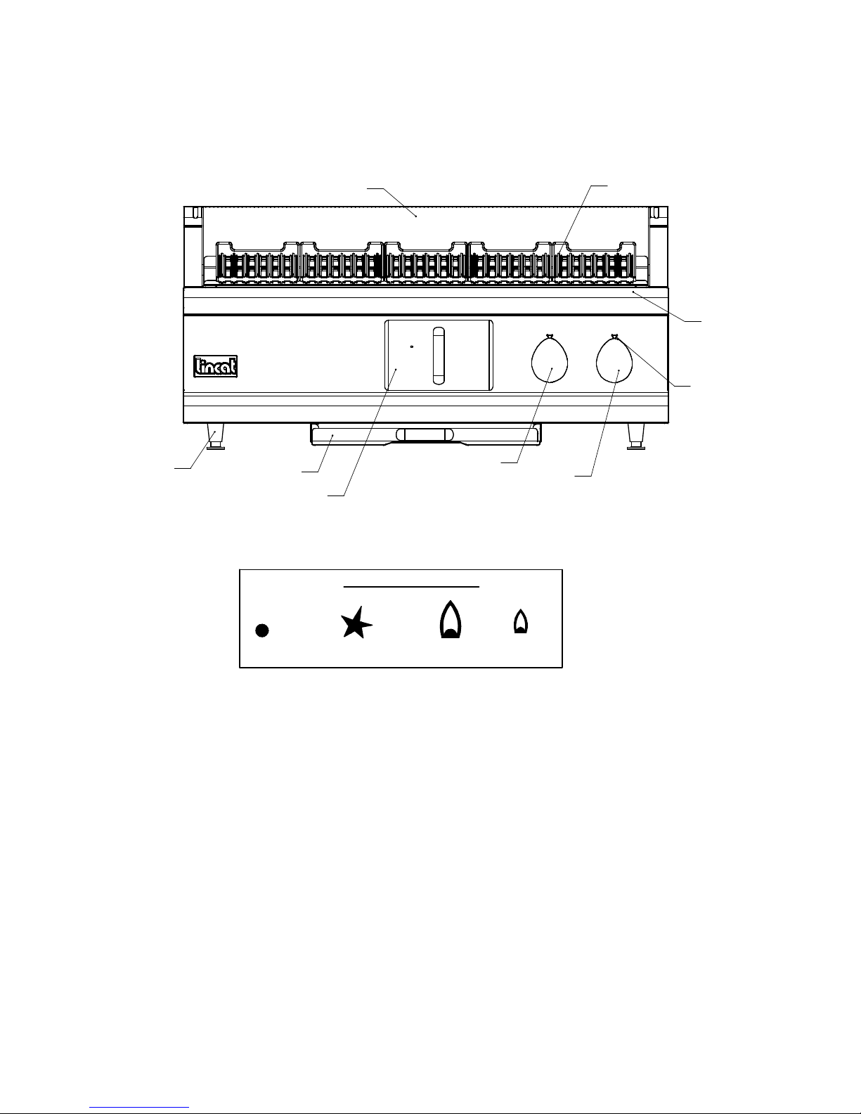
Control Panel
ADJUSTABLE FEET
DEBRIS TRAY
FAT DRAWER
SPLASH SURROUND
KNOB INDICATORS
BRANDING PLATES
DRAIN TRAY
ON/OFF INDICATORS
LH BURNERS CONTROL KNOB
RH BURNERS CONTROL KNOB
OFF PILOT
IS141 ECN 2740 2
HIGH LOW
Page 3
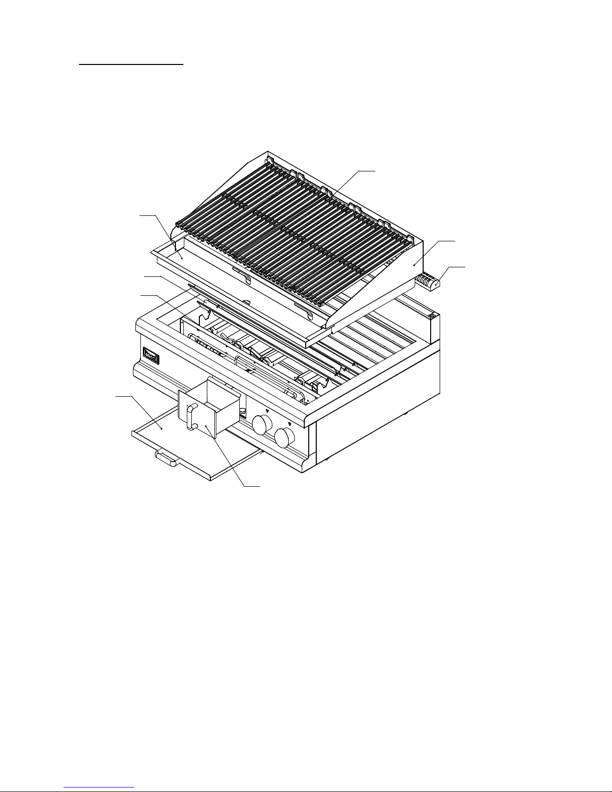
Assembly of Enclosures
Before lighting the appliance please ensure the heat transfer channels, their supports, the drain tray,
fat collection drawer, splash surround, branding plates, flue top and debris tray are in the correct
positions.
6
3
5
1
2
8
4
1. HEAT TRANSFER CHANNELS x 9
2. HEAT TRANSFER CHANNEL SUPPORT ARMS x 2
3. DRAIN TRAY
4. FAT DRAWER
5. SPLASH SURROUND
6. BRANDING PLATES x 5
7. FLUE TOP
8. DEBRIS TRAY
7
IS141 ECN 2740 3
Page 4
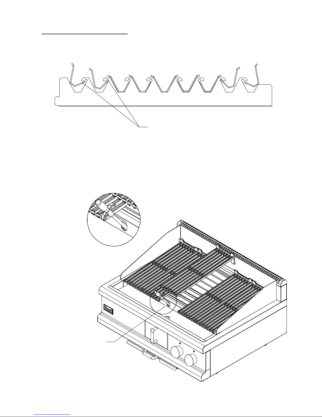
Positioning of heat transfer channels.
4 FACING FRONT
FRONT
1 CENTRE
TO FIT HEAT TRANSFER CHANNELS - LOCATE SHORT EDGE
BENEATH HOOK OF SUPPORT ARM AND TWIST DOW N INTO PLACE
4 FACING REAR
The positioning of the heat transfer channels is critical to the correct functioning of the appliance.
Please follow the above diagram when fitting the heat transfer channels.
Lighting the Appliance
BACK
DETAIL A
MOVE BRANDING PLATE AND PLACE
IGNITER INTO LIGHTING TUBE.
REPEAT FOR OTHER SIDE.
IS141 ECN 2740 4
A
Page 5

Please ensure that the gas isolation valve for the appliance is turned to the open position before
attempting to light this unit.
1) Pass the piezo ignitor wand through the access holes in the rear of the drain tray and down
the ignition guide channel until it reaches the stop point.
2) With the control knob in the OFF position, depress the control knob fully, to allow gas
through to the pilot burner, hold in and turn anti-clockwise to the pilot position.
3) Slowly click the Piezo ignitor wand until the pilot is lit.
4) Keep the control knob depressed for 20 seconds to establish the pilot light.
5) Should the pilot fail to remain lit, return the control knob to the OFF position and repeat the
process.
6) Repeat steps 1 –5 to light the pilot to the second set of burners.
NOTE: The OG7402 Chargrill has two sets of controls and dual pilots. Ensure that both pilots
are lit before lighting the main burners. The left hand control knob controls the larger, left
hand cooking zone of 3 burners which is 60% of the full grid. The right hand control knob
controls the 2 right hand burners, or 40% of the grid.
7) To light the main burner, turn the control knob anti-clockwise to the high setting. Note: On
the high setting, the chargrill will take approximately 20 minutes to achieve full
working temperature from cold.
NOTE: This appliance must not be used (or left) with the control knobs positioned between
the pilot position and the full on position.
8) To run the appliance on low, turn the control knob fully anti-clockwise to the LOW setting.
9) The heat input can now be adjusted between High and Low settings to give the desired
working temperature.
10) Repeat steps 7 – 9 to light the second set of burners.
Warning: Never attempt to light the burners through the heat transfer fins.
Standby
Once the pilots are lit whole or part of the unit can be left on standby by leaving the control knob in
the pilot position. The pilot light(s) will remain lit but the burners will be shut down.
Shutting down the appliance
To turn the appliance off completely turn the control knob(s) clockwise to the to the OFF position.
Warning: After operation, some parts of the appliance will remain hot for a period of time.
Please take care to avoid accidental burns.
Cleaning
Ensure gas supply is isolated before commencing cleaning.
After complete shut down and cooling parts of this unit can be dismantled for cleaning, in the
following order: Refer to Assembly of Enclosures diagram.
IS141 ECN 2740 5
Page 6

Cleaning (cont)
Branding plates x 5
Splash surround x 1
Heat transfer channel support arms x 9
Drain tray x 1
Profile support arms x 2
Fat collection drawer x 1
Flue cover x 1
Debris tray x 1
All parts can be cleaned in a commercial dishwasher, with the exception of the fat collection drawer
which should be washed by hand.
The unit, including burner covers and internal surfaces, can be cleaned using warm detergent
solution.
Take care not to allow water or traces of detergent to remain on the burners.
Do not use abrasives
Do not use any products containing chlorine to clean stainless steel surfaces.
Do not clean the appliance using water jets.
Note: For heavy, stubborn deposits a de-greasing agent ‘CARBON-OFF’ is available from Lincat
upon request
Warning: Do not spray water or cleaning fluids inside the unit
NB. When branding plates are dry, lightly coat with oil.
When dry reassemble the unit in reverse order.
This appliance should be serviced and maintained regularly, according to the service
instructions. Before carrying out any maintenance on this appliance, isolate from the gas
supply. See “Service Information” below.
SERVICE INFORMATION
Gas catering equipment should be routinely serviced to ensure a long trouble free life. It is
recommended that this appliance is serviced every 6 months by a competent gas engineer.
For help regarding the installation, maintenance and use of your LINCAT equipment, please call:
LINCAT GROUP SERVICE HELP DESK
AUTHORISED SERVICE AGENTS
We recommend that all servicing other than routine cleaning be carried out by our authorised
service agents.
We cannot accept responsibility for work carried out by other persons.
Please quote both the model and serial numbers from the data plate attached to the unit. Give brief
details of the service requirement.
If possible please quote the product code of the part number you require.
IS141 ECN 2740 6
01522 875520
Page 7

Work carried out under warranty will normally be undertaken only during normal working hours,
i.e. Monday to Friday, 8.30 a.m. - 5.30 p.m.
CONDITIONS OF GUARANTEE
The guarantee does not cover:-
1) Accidental breakage or damage.
2) Operational misuse, wear and tear from normal usage, incorrect adjustment, or neglect.
3) Incorrect installation, maintenance, modification or unauthorised service work.
SPARE PARTS LIST
Part number Description
BP10 Branding Plate
BU66 Burner
CO113 Copper Washer (Burner Injector)
CO128 Unequal Tee (10mm to 8mm)
CO87 Test Nipple
HA78 Handle
JE13 Burner Injector – Propane and Butane
JE31 Pilot Injector - Natural
JE32 Pilot Injector – Propane and Butane
JE46 Burner Injector – Natural
KN174 Control Knob
LE38 Adjustable Leg
LI42 Branding Plate Lifter
PG10 Governor
PI25 Pilot Assembly
SI14 Ignitor Wand
TC03 Thermocouple
TC05 Thermocouple Nut
TC06 Thermocouple Sleeve
TC24 Thermocouple Split Nut – M9
VA45 Control Valve
WA08 Fibre Washer (Burner Injector)
WB01 Cleaning Brush
IS141 ECN 2740 7
 Loading...