

Page 1
IS 583 ECN 3851 Page 1 of 14
Installation, Operating, Servicing and
Conversion Instructions
Opus 800 Electric Heated Tilting Bratt Pan
OE8802
Please make a note of your product details for
future use:
Date Purchased:_________________________
Model Number:__________________________
Serial Number:__________________________
Dealer:_________________________________
_______________________________________
Page 2
IS 583 ECN 3851 Page 2 of 14
CONTENTS
Important Information 2
Warnings and Precautions 3
Technical Data 3
Checklist of Enclosures 4
Installation and Commissioning 4
Operating Instructions 8
Cleaning 10
Servicing, Maintenance and Component Replacement 10
Conversion 12
Fault Finding 13
Spare Parts List 14
Accessories 16
Service Information and Guarantee 16
IMPORTANT INFORMATION
Read these instructions carefully before using this product, paying particular attention
to all sections that carry warning symbols, caution symbols and notices. Ensure that
these are understood at all times
.
WARNING!
This symbol is used whenever there is a risk of personal injury.
CAUTION!
This symbol is used whenever there is a risk of damaging your Lincat product.
NOTE:
This symbol is used to provide additional information, hints and tips.
KEEP THIS MANUAL FOR FUTURE REFERENCE
Page 3
IS 583 ECN 3851 Page 3 of 14
WARNINGS AND PRECAUTIONS
This appliance must be installed, commissioned, and serviced by a qualified person
in accordance with national and local regulations in force in the country of
installation.
Strip plastic coating and clean the appliance before use.
During operation parts may become hot - avoid accidental contact.
If the supply cord is damaged, it must be replaced by the manufacturer, its service
agent or similarly qualified person.
Ensure that the plug/socket is accessible at all times.
Disconnect this appliance before servicing, maintenance or cleaning.
This appliance should only be used by a qualified adult.
TECHNICAL DATA
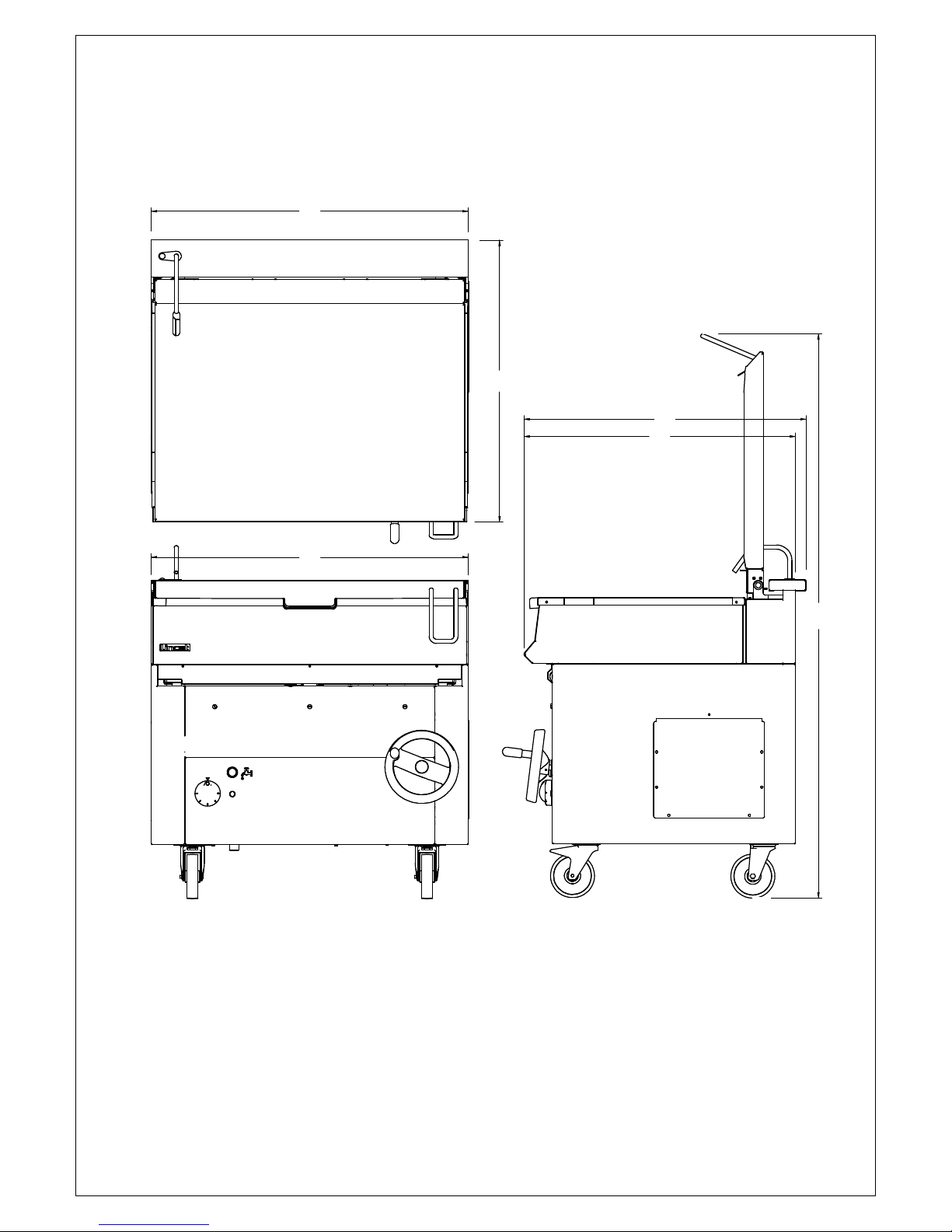
Model OE8802
Height (mm) 900
Width (mm) 900
Depth (mm) 800
Height - Lid Up (mm) 1600
Weight (kg) 184
Total power rating (kW) 12
Supply 1N ~+E
230V 50-60Hz
Current (A)
52.2
Supply 3N~+E
400V 50-60Hz
Current (A)
L1 17.4
L2 17.4
L3 17.4
Thermostat range Marked 1 to 5 – (Approx. 90-280°C)
Cold water mains G3/4”
Frequency 50/60Hz
Page 4
IS 583 ECN 3851 Page 4 of 14
CHECK LIST OF ENCLOSURES
Warranty card
Instructions manual
INSTALLATION AND COMMISSIONING
This appliance must only be used by qualified professionals.
An equipotential bonding terminal is provided to allow cross bonding with other
equipment.
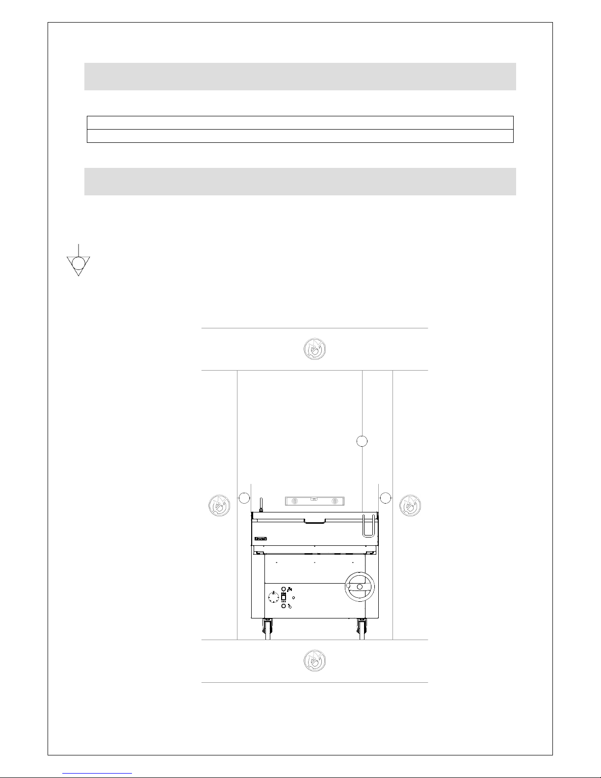
Install this appliance on a level surface ensuring all air vents are unobstructed. Any
partitions, walls or furniture must be of non-combustible material.
Minimum distances A 50mm B 1000mm – see Fig 1.
B
AA
Figure 1
Page 5
IS 583 ECN 3851 Page 5 of 14
This appliance must be earthed.
If replacing the plug connect the terminals as follows:
Green and Yellow wire Earth E
Blue wire Neutral N
Brown wire Live L
Means of isolation with at least 3mm contact separation in all poles must be
incorporated into the fixed wiring of this appliance.
The fixed wiring insulation must be protected by insulated sleeving having a
temperature rating of H 07 RN-F
Supply cords shall be oil resistant, sheathed flexible cable not lighter than ordinary
polychloroprene or equivalent elastomer sheathed cord (code 60245 IEC 57)
The appliance must be installed at least 50mm from any side walls and 100mm from
any back walls
If the appliance must be fitted near walls, partitions kitchen furniture etc we
recommend they are made from non-inflammable material, otherwise they should be
covered with a suitable heat-resistant material. Full attention must be paid to fire
prevention regulations
The water inlet must be between 50 and 300 kPa.
If this appliance is fitted with castors, use caution at all times when manipulating or
moving, and lock castors when appliance is in position. Drain the appliance BEFORE
moving it.
Earth and equipotential connection
The appliance must be connected to an equipotential system – the terminal is
situated near the entry point of the electrical supply cable and is marked by the
symbol
The appliance must be earthed. Connect the earth cable to the terminal near the
terminal block marked by the symbol
START THE APPLIANCE FOLLOWING THE OPERATING INSTRUCTIONS
Inspection of the electrical supply
Start the appliance following the instructions for use. Check the heating devices are
working correctly.
Raise and lower the tank, dependant on model. Ensure that the cut out operates
when the tank is raised, and that power is restored when the tank is lowered into the
working position again.
In the event of a malfunction, this appliance is equipped with a safety thermostat that
interrupts the supply. After the cause has been identified and rectified, restart the
appliance by resetting the thermostat manually – push the red button situated under
the base at the front left hand side.
If necessary, please consult ‘Potential troubleshooting and solutions’ section.
Page 6
IS 583 ECN 3851 Page 6 of 14
OPERATING INSTRUCTIONS
Only qualified or trained personnel should use this appliance.
Do not use this appliance as a deep or shallow fryer.
Warning: The element will only heat when the tank is positioned correctly in the
down position.
Warning: When griddling in the tank the addition of water or stock should only take
place at a temperature and rate that avoids a severe reaction in the pan which could
cause scolds and burns if done carelessly
a
b
c
g
f
e
d
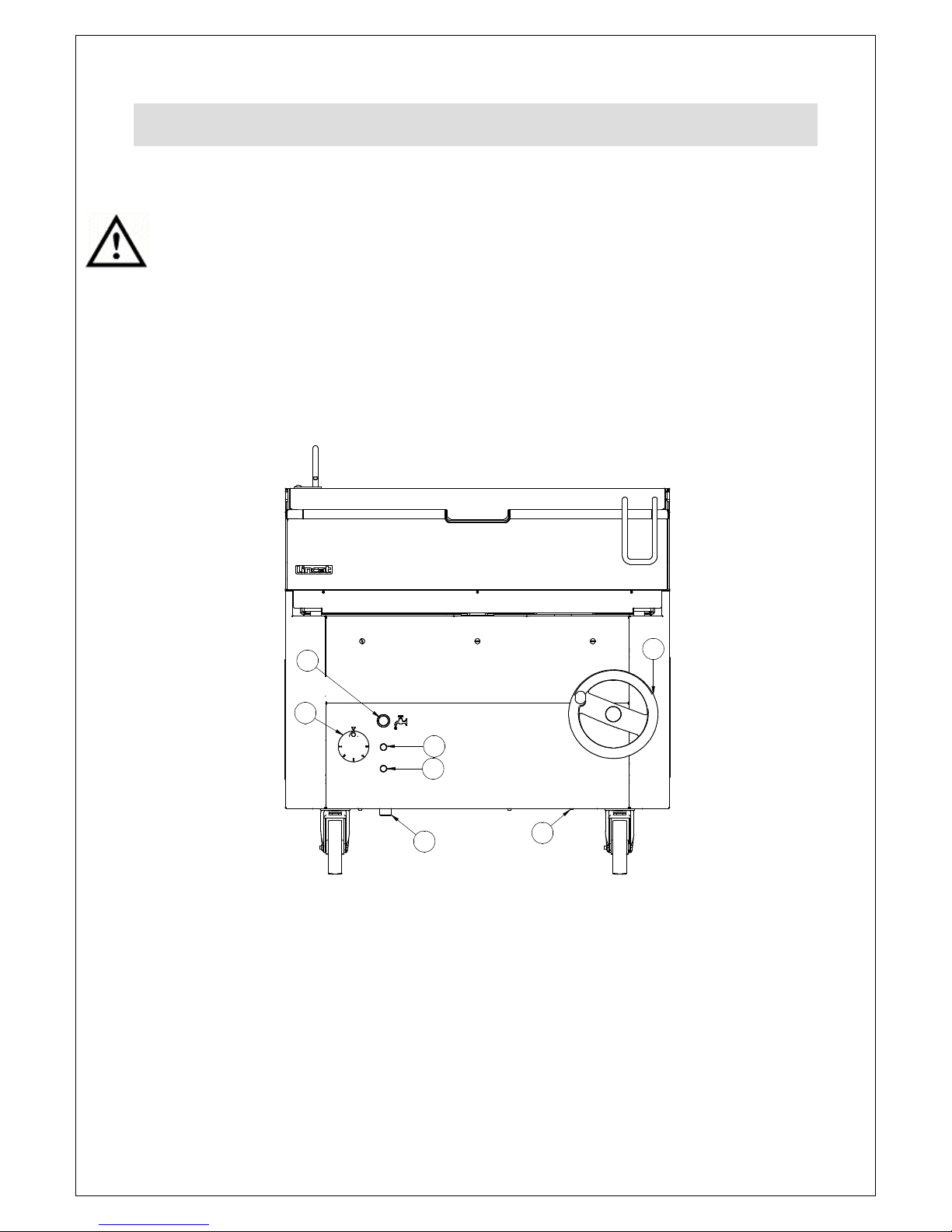
Figure 2
Bratt Pan
The bratt pan is fitted with control knob, (see figure 2) power indicator lamp, heating
indicator lamp, a hand wheel for tilting the pan and a button for filling with water.
The control knob (a) sets the temperature of the tank and the gas burner ignites
automatically when switched to the on position.
The lower settings 1- 2 allow for a gentle heat once the food product has been
brought to temperature. This is ideal if the food is prone to burning - in particular milk
or cream based products.
Page 7
IS 583 ECN 3851 Page 7 of 14
Button (b) for filling the tank with water.
The green neon (c) indicates that the power is on.
The amber neon (d) indicates that the heating element is on.
The hand wheel (e) raises (clockwise) and lowers (anticlockwise) the tank.
The water connection is shown at (f)
The Safety thermostat can be reset by pressing the button (g) after the appliance has
cooled down
The gas valve control knob displays the following: Off
1 to 5 where 1 approximates to 90°C and 5 approximates to 280°C
Caution: Ensure that the container into which the food product is emptied is suitable
to contain food at a high temperature.
Caution: The lid must be lifted fully up before operating the tank tilting mechanism.
The tank may be raised or lowered at any time during the cooking cycle. To do this,
lift the lid and turn the hand wheel clockwise on the appliance to raise and empty the
tank. Turn the wheel counter-clockwise to lower the tank.
Moderate the speed to obtain an even and controlled pour, this will vary depending
on viscosity of contents
Filling the tank with water
Caution: Ensure the tank is seated correctly in the lowered position before
adding water.
Press the water load button to add water.
Switching on the bratt pan
Set the control knob to the desired setting.
Switching off the bratt pan
Turn the thermostat knob to the ‘Off’ position
Turn the appliance off at the electrical supply.
Emptying the tank
Prepare a suitable vessel beneath the discharge spout of the tank.
Lift the lid.
Slowly raise the tank by turning the wheel clockwise.. Take care not to create ‘surge’
of liquid contents by attempting to raise the tank too quickly.
Page 8
IS 583 ECN 3851 Page 8 of 14
CLEANING
Do not use a water jet or steam cleaner, and do not immerse this appliance.
Always disconnect the appliance from the mains supply before cleaning or
maintenance.
Clean all panels with warm water and mild detergent do not use abrasive materials.
Dry with a soft cloth.
If the appliance is not to be used for a lengthy period, disconnect from the mains
supply and clean well.
SERVICING, MAINTENANCE AND
COMPONENT REPLACEMENT
All servicing, maintenance and component replacement on this appliance should be
carried out by one of our recommended service engineers.
Disconnect the appliance from the electricity and before greasing the lifting
mechanism screw thread. It is recommended that the lifting mechanism is greased at
least every six months. (Rocol Foodlube Universal 2) This is accessed by lifting the
tank which will give access to the lifting screw thread. The lid springs should be done
at the same time. These are accessed by removing the cover located at each end
and centrally by screws
Do not use a water jet or steam cleaner, and do not immerse this appliance.
Always disconnect the appliance from the mains supply before cleaning or
maintenance.
Steel parts can be cleaned using a cloth with water and mild detergent – aggressive
or abrasive cleaning substances such as steel wool or chlorine based products must
be avoided.
Do not use sharp objects during cleaning.
If the appliance is not to be used for a lengthy period, disconnect from the mains
supply and clean well.
Replacing components with spares
IMPORTANT: Before making any repairs disconnect the appliance from the
electrical supply.
Page 9

IS 583 ECN 3851 Page 9 of 14
Energy regulator
Remove hand wheel.
Remove control knob and facia panel.
Unscrew the fixing screws and disconnect the wiring.
Remove.
Replace.
Limiting thermostat
Remove hand wheel.
Remove front lower facia panel.
Unscrew the fixing screws and disconnect the wiring.
Remove the thermostat from the bracket.
Remove thermostat bulb long cover plate.
Remove the thermostat bulb from the bracket.
Safety thermostat
Remove hand wheel.
Remove facia panel.
Unscrew the fixing screws and disconnect the wiring.
Remove thermostat bulb long cover plate.
Remove the thermostat bulb from the bracket.
Replace all removed parts in reverse order
Amber neon
Remove hand wheel.
Remove facia panel.
Unscrew the neon and disconnect the wiring.
Replace all removed parts in reverse order
Water valve replacement
Remove left hand access cover.
Disconnect water valve
Unscrew and remove from pipe and brackets
Replace all removed parts in reverse order
Tank position micro switch
Remove right hand access cover.
Disconnect micro switch
Remove from bracket
Re-adjust to ensure that the micro switch cuts out when the tank starts to lift of its
rest position
Replace all removed parts in reverse order
Contactor
Remove lower facia panel.
Unclip contactor.
Disconnect wiring.
Rewire replacement contactor
Reclip contactor.
Replace flame controller.
Replace all removed parts in reverse order
Page 10
IS 583 ECN 3851 Page 10 of 14
Please refer to the Service Help Desk number on the final page of this manual.
POTENTIAL TROUBLESHOOTING AND SOLUTIONS
Even during correct use of the appliance, malfunctions and breakdowns may occur.
Common situations are listed below, and checks an installer should make before
contacting the technical support centre are indicated.
If after checking, the problem remains, switch the appliance off immediately and
disconnect it from the power supply. Contact the technical support centre.
Intervention of safety thermostat
Thermostat defective.
Tank lifting micro switch defective.
Difficult or unsuccessful temperature regulation
Defective energy regulator.
Defective thermostat.
Difficult or noisy operation of the tank lifting mechanism
Poor lubrication of moving parts.
Water fill not operational
No power to appliance.
Tank not fully down.
Tank lifting micro switch defective.
Defective water fill solenoid
FAULT FINDING
Page 11
IS 583 ECN 3851 Page 11 of 14
Part Number
Description
872-027-00 TRAPEZOIDAL THREADED
872-038-00 SHOULDERED SWIVEL NUT
872-039-00 BRATT LID HANDLE
BE40 PILLAR BLOCK BEARING
BU254 FLANGED JOURNAL BEARING
CA143 CASTOR OPUS SWIVEL
CA145 CASTOR OPUS SWIVEL
CO264 SIEMANS CONTACTOR
EN10 EGO ENERGY REGULATOR
HA112 SPOKED HANDWHEEL
IS583 OE8802 BRATT PAN USER INS
KN511 OPUS-800 KNOB BRATT PAN
NE46 GREEN NEON
NE47 AMBER NEON
SO27 WATER VALVE NO
SP92 LID SPRING
SW80 GREEN BUTTON (SOLID)
SW82 SWITCH ELEMENT N/O
TH63 SAFETY CUT OUT STAT 365 C
TS03 TRAPEZOIDAL SCREW
X54900 P ONLY: MICRO SWITCH
X59200 3P 40A TERMINAL BLOCK
Y19200 SINGLE OVEN THERMOSTAT
SPARE PARTS LIST
Page 12
IS 583 ECN 3851 Page 12 of 14
900
800
770
800
1600
900
Page 13
IS 583 ECN 3851 Page 13 of 14
Part Number
Description
Used on
For help with the installation, maintenance and use of your Lincat equipment,
please contact our service department:
UK: 01522 875520
For non-UK customers, please contact your local Lincat dealer
All service work, other than routine cleaning should be carried out by one of our
authorised service agents. We cannot accept responsibility for work carried out by
other persons.
To ensure your service enquiry is handled as efficiently as possible, please tell us:
• Brief details of the problem
•
Product code
All available on serial plate
•
Type number
•
Serial number
Lincat reserve the right to carry out any work under warranty, given reasonable
access to the appliance, during normal working hours, Monday to Friday, 08:30 to
17:00.
GUARANTEE
This unit carries a comprehensive UK mainland 2 year warranty. The guarantee is
in addition to, and does not diminish your statutory or legal rights.
The guarantee does not cover:
• Accidental damage, misuse or use not in accordance with the manufacturer’s
instructions
• Consumable items (such as filters, glass, bulbs, slot toaster elements and door
seals.)
ACCESSORIES
SERVICE INFORMATION
Page 14

IS 583 ECN 3851 Page 14 of 14
• Damage due to incorrect installation, modification, unauthorised service work or
damage due to scale, food debris build-up, etc.
The manufacturer disclaims any liability for incidental, or consequential damages.
Attendance is based on reasonable access to the appliance to allow the authorised
technician to carry out the warranty work.
Service calls to equipment under warranty will be carried out in accordance with the
conditions of sale. Unless otherwise specified, a maximum of 15 minutes of
administrative time, not spent directly carrying out servicing work, is provided for
within the warranty. Any requirement for staff attending the call to spend greater time
than 15 minutes due to administrative requirements, such as on health and safety risk
assessments, will be chargeable at the prevailing rate.
 Loading...