

Lincat Opus 800, OD8006, OD8007, OD8007-A002, OD8006-A002 Installation, Operating, Servicing And Conversion Instructions
Page 1

Please make a note of your product details for
future use:
Date Purchased:_________________________
Model Number:__________________________
Serial Number:__________________________
Dealer:_________________________________
_______________________________________
Installation, Operating, Servicing and
Conversion Instructions
Opus 800 Dual Fuel Ranges
OD8006-A002 & OD8007-A002
IS642 ECN 4259 Page 1 of 20
Page 2

CONTENTS
Important Information
2
Warnings and Precautions
3
Technical Data
4
Checklist of Enclosures
5
Installation and Commissioning
6
Operating Instructions
8
Cleaning
9
Servicing, Maintenance and Component Replacement
12
Conversion
16
Fault Finding
17
Spare Parts List
18
Accessories
19
Service Information and Guarantee
20
IMPORTANT INFORMATION
Read these instructions carefully before using this product, paying particular attention to
all sections that carry warning symbols, caution symbols and notices. Ensure that these
are understood at all times.
WARNING!
This symbol is used whenever there is a risk of personal injury.
CAUTION!
This symbol is used whenever there is a risk of damaging your Lincat product.
NOTE:
This symbol is used to provide additional information, hints and tips.
KEEP THIS MANUAL FOR FUTURE REFERENCE
IS642 ECN 4259 Page 2 of 20
Page 3

WARNINGS AND PRECAUTIONS
This appliance must be installed, commissioned, serviced and converted by a qualified
person in accordance with national and local regulations in force in the country of
installation.
Strip plastic coating and clean the appliance before use.
During operation parts may become hot - avoid accidental contact.
Parts protected by the manufacturer shall not be adjusted by the user.
Do not obstruct or block the flue.
Disconnect this appliance before servicing, maintenance or cleaning.
IS642 ECN 4259 Page 3 of 20
Page 4

TECHNICAL DATA
Model
OD8006
OD8007
Dimensions
Height (mm)
900
900
Width (mm)
600
900
Depth (mm)
800
800
Weight (kg)
109
154
Hob Cooking Surface w x d (mm)
600 x 600
900 x 600
Useable Oven Capacity w x d x h (mm)
500 x 540 x 400
715 x 540 x 400
Oven Shelf w x d (mm)
500 x 540
715 x 540
Heat Input (Gross)
Total - Natural
30.0kW
45.0kW
Total - Propane
26.8kW
40.2kW
Hob Burner - Natural
7.5kW
Hob Burner - Propane
6.7kW
Hob Low
2.0kW
Connection and Operating Pressures
Gas Inlet Connection
½” BSP (Rp ½)
¾” BSP (Rp ¾)
Supply Pressure – Natural G20 I2H
20mbar
Supply Pressure – Propane G31 I
3
P
37mbar
Gas Consumption
Total - Natural
2.86 m3 h-1
4.06 m3 h-1
Total - Propane
1.92 kg h-1
2.87 kg h-1
Hob – Natural
0.71 m3 h-1
Hob – Propane
0.48 kg h-1
Oven Temperature
120 – 280 C
Electrical
Total Power Rating @ 230V single phase
4.032 kW
6.06 kW
Total Power Rating @ 400V three phase
Phase
1
Phase
2
Phase
3
1.36 kW
2.67 kW
N/A
Phase
1
Phase
2
Phase
3
2.064
kW
2.0 kW
2.0 kW
IS642 ECN 4259 Page 4 of 20
Page 5

CHECK LIST OF ENCLOSURES
Model
OD8006
OD8007
Tick
Warranty card
1 1
Instructions manual
1 1
Pan Supports
4 6
Wire Shelf 3 3
IS642 ECN 4259 Page 5 of 20
Page 6

B
A A
INSTALLATION AND COMMISSIONING
Site this appliance beneath an extraction canopy for the removal of combustion products.
When making the gas connection, fit an isolating cock into the supply line close to the
appliance for emergency shutdown or servicing purposes.
Installation must include sufficient ventilation to prevent the occurrence of unacceptable
concentrations of substances harmful to health in the room of installation. There must
be a minimum free area of 4.5cm2 per kW of total heat input.
Allow for a sufficient flow of fresh air for complete gas combustion.
Do not connect directly to any flue, ducting or mechanical extraction system.
The gas supply hose or tubing shall comply with national requirements in force and
shall be periodically examined and replaced as necessary.
An equipotential bonding terminal is provided to allow cross bonding with other
equipment.
Install this appliance on a level surface ensuring all vents are unobstructed.
Any partitions, walls or furniture must be of non-combustible material.
Minimum distances = A, 50mm B, 1000mm – see Fig 1.
If this appliance is fitted with castors, use caution at all times when manipulating or
moving, and lock castors when appliance is in position.
Fig. 1
IS642 ECN 4259 Page 6 of 20
Page 7

NOTE
SITING
The installer must ensure that all regulations are met and that there is an unobstructed
minimum distance of 1000mm from the top of the flue to the ceiling, which must be of
non-combustible material.
The appliance should be installed on a level surface ensuring the unit is stable and
firmly located.
Any partitions, walls or kitchen furniture in close proximity must be of non-combustible
materials and not be closer than 50mm from the sides of the flue.
The Installer shall pay particular attention, in order not to disturb the air combustion
admission nor the combustion products evacuation of appliances fitted with open burners.
GAS SUPPLY AND CONNECTION
The gas inlet connection is at the rear of the appliance. The pipe work should be of
adequate size but not smaller than the gas inlet connection at the rear of the appliance,
i.e. Rp ½” BSP (OD8006) & Rp ¾” BSP (OD8007).
The gas supply tubing or hose shall comply with national requirements in force and shall
be periodically inspected and replaced as necessary.
All joints made must be leak free.
Final gas connection to the appliance and gas supply shall comply with local regulations.
When making the connection to the appliance an isolating cock should be fitted into the
supply line close to the unit, for emergency shutdown or servicing purposes.
SUPPLY PRESSURES
The appliance is connected directly to the gas supply where the gas supply pressure
is controlled at the source of inlet in the building or via the governor attached to the
bottle gases. See Technical Data for the supply pressures.
To gain access to the gas pressure test nipple the fascia panel requires removal.
The test nipple is situated in the centre of the manifold rail.
Remove the blanking screw and attach a pressure gauge to the boss of the test nipple.
Light the oven burner and set thermostat to the highest setting and check the pressure.
For Propane with a 50mbar supply pressure a govenor is required for
adjustment to 37mbar.
ELECTRICAL SUPPLY AND CONNECTION
Connection of the electrical supply cable is made at the rear of the unit. Remove the
protective cover and fit a suitable cable into the cable relief and then to the inlet terminal
block. The unit is supplied for connection to a three-phase supply. Connections are
provided to allow termination of all three-phase cables, although only two are used to
power the unit. If the unit is to be fed from a single-phase supply then the two supply
terminals will need to be connected together using a wire link.
LOCKING OF WHEELS
When the appliance has been installed in its intended position the front castors
should be locked by depressing the locking tabs on the castors.
Locks should only be released for the intention of moving the appliance
for cleaning purposes and or routine servicing of the appliance.
IS642 ECN 4259 Page 7 of 20
Page 8
OPERATING INSTRUCTIONS
This appliance is only for professional use and should only be used by qualified
personnel.
Ensure that the person responsible understands how to light, safely operate, clean
and shut down the appliance and is made aware of the position and operation of the
gas isolating cock in the event of an emergency.
Ensure that all controls have free and easy movement, if not contact a qualified service
engineer.
This appliance is intended to be used for baking or roasting in the oven and for pan
frying or boiling on the hob.
All users should know how to clean burner caps and to correctly locate the burner
cap on the burner body.
LIGHTING SEQUENCE – HOB BURNER
Open the main gas cock.
Push in the control knob then rotate anti-clockwise to any position to allow gas
through to the burner. Manually light this burner using a taper or piezo ignitor
wand.
On establishing a flame at the burner, keep the knob depressed for
approximately 15 seconds then release. The burner should remain lit.
POTS AND PANS
The minimum recommended pan size should have a base diameter not less
than 150mm.
The maximum recommended pan size per burner should not exceed a base
diameter of 360mm.
Under no circumstances should multiple burners be covered by a single pan
or container.
OVEN SETTING
Check the green ‘power on’ neon on the fascia panel is illuminated.
Set the control knob to the desired temperature in degrees Celsius. The orange
light will illuminate indicating that power is being supplied to the elements.
The orange light will go out when the oven has achieved the set temperature.
Periodically the orange light will illuminate to indicate that the oven temperature
has fallen and the elements are turned on to top up the temperature.
SHUT DOWN
To shut down the appliance rotate all control knobs clockwise to the OFF position.
The gas supply stopcock or bottle valve should now be closed.
After operation, some parts of the appliance will remain hot for a period of
time; care should be taken to avoid risk of burns.
OPENING OF THE OVEN DOOR
Care must be taken to avoid injury when opening the oven door, when the oven is
in use as hot air will rapidly escape.
IS642 ECN 4259 Page 8 of 20
Page 9

MM
NN
QQ
CLEANING
Hob Burner Components
Part
Description
MM
Burner Body
NN
Burner Cap
QQ
Thermocouple
Your Lincat product has a manufacturer’s warranty. This requires you to maintain and
care for your product and follow maintenance instructions. If you fail to maintain your
unit or damage components Lincat may charge you for a warranty repair. Please check
the website for terms and conditions.
Do not use a water jet or steam cleaner, and do not immerse this appliance.
Clean all panels with warm water and mild detergent do not use abrasive materials.
Rinse and dry thoroughly with a soft cloth.
Hob Components.
Pan Supports – Remove from the appliance, taking careful note of the orientation of the
locating feet which must always be fitted with the feet to the sides (left & right) of the
appliance.
Fig. 2
The Pan Supports can be cleaned with a mild detergent and hot water solution using a
soft bristled brush. Rinse and dry thoroughly with a dry cloth.
Burner Cap – Remove from the appliance taking care not to damage the thermocouple
which protrudes from the support.
IS642 ECN 4259 Page 9 of 20
Fig. 3
The Burner Body can be cleaned with a mild detergent and hot water solution using a
soft bristled brush. Rinse and dry thoroughly with a dry cloth.
Page 10

RR
TT
Hob Burner Components
Part
Description
RR
Pan Support Channel
Hob Burner Components
Part
Description
TT
Drip Trays
Pan Support Channel – Remove from the appliance taking note of its fixing points.
Fig. 4
The Pan Support Channel can be cleaned with a mild detergent and hot water
solution using a soft bristled brush. Rinse and dry thoroughly with a dry cloth.
Fig. 5
The Drip Trays can be cleaned with a mild detergent and hot water solution using a
soft bristled brush. For stubborn deposits a de-greasing agent may be used.
Rinse and dry thoroughly with a dry cloth.
IS642 ECN 4259 Page 10 of 20
Page 11

VV
Oven Components.
Oven Components
Part
Description
VV
Thermostat Phial
Oven Shelves & Side Hangers – Open the oven doors and remove the shelves and
hangers.
To remove shelves, tilt up the rear and slide shelf forward.
To remove side hanger, lift hanger up and then pull into centre of oven.
Fig. 6
The Shelves and Side Hangers can be cleaned with a mild detergent and hot water
solution using a soft bristled brush. For stubborn deposits a de-greasing agent may
be used.
Rinse and dry thoroughly with a dry cloth.
Oven Drip Tray - Open the oven doors and remove the drip tray from the appliance.
The Oven Drip Tray can be cleaned with a mild detergent and hot water solution using a
soft bristled brush. For stubborn deposits a de-greasing agent may be used.
Rinse and dry thoroughly with a dry cloth.
Oven Compartment – Open the oven doors and leave the drip tray in situ.
The sides, top and back panels can be cleaned with a mild detergent and hot water
solution using a soft bristled brush. For stubborn deposits a de-greasing agent may
be used.
Rinse and dry thoroughly with a dry cloth.
Take care not to disturb the burner components or the thermostat phial.
IS642 ECN 4259 Page 11 of 20
Fig. 7
Page 12
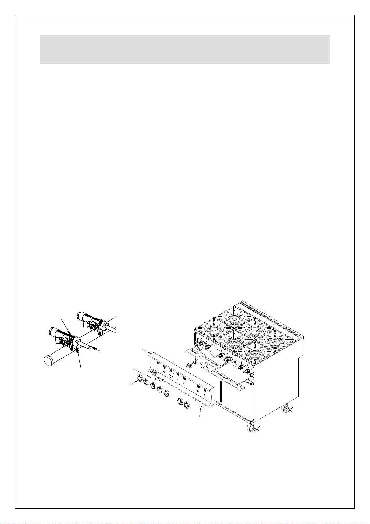
XX
YY
ZZ
CC
BB
DD
DD
SERVICING, MAINTENANCE AND
COMPONENT REPLACEMENT
All servicing, maintenance and component replacement on this appliance should be
carried out by one of our recommended service engineers.
SERVICE ACCESS
To access and service the gas control valves – Recommended every 6 months
Remove the control knobs CC and facia panel BB to gain access
to the valves.
Remove the two fixing screws XX securing the valve boss YY and carefully
withdraw the spindle ZZ from the valve.
Grease as necessary and refit parts. Carry out gas soundness check.
To service the thermocouples – Recommended every 6 months
Remove the control knobs CC and facia panel BB to gain access to gain
access to the thermocouples.
Check millivolt output and replace if required.
Check thermocouples are secure and tighten if required.
FACIA PANEL REMOVAL
Open the oven doors and remove the drip trays.
Remove the control knobs CC and the two fascia fixing screws DD.
The fascia panel can now be lifted away.
Take care not to damage the thermostat phial.
Fig. 8
Fig. 9
OPERATIONAL CHECK
Commissioning must include an operational check of all controls.
Check that each burner can be lit at both full rate and low rate.
Check that each burner will remain lit when turned to low rate.
IS642 ECN 4259 Page 12 of 20
Page 13
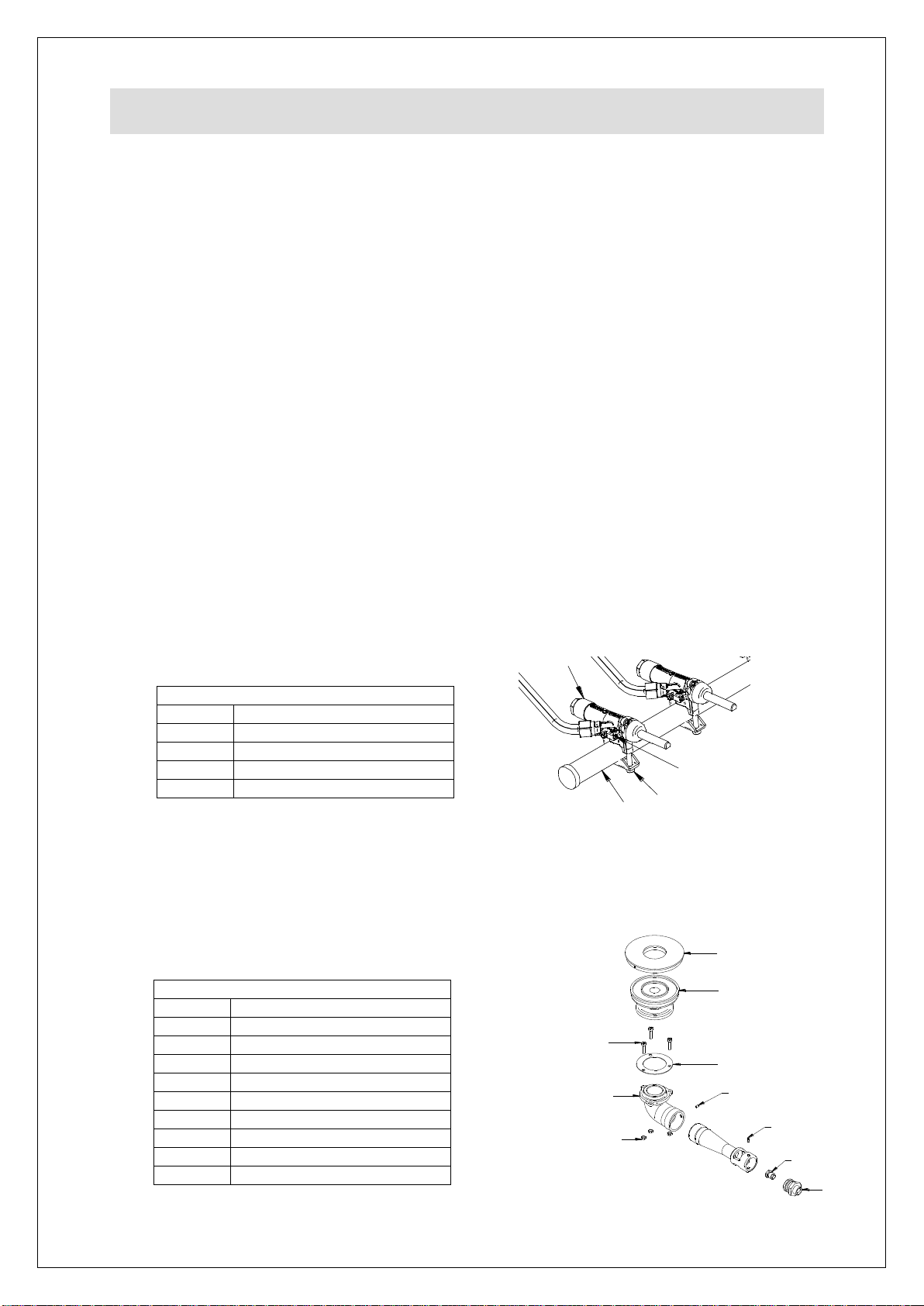
NN
MM
LL
HH
HH
JJ
KK
GG
FF
PP
G
H
J
K
M
L
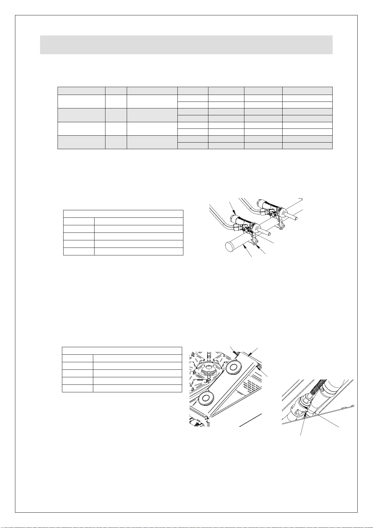
Hob Thermocouple
Hob Burner Components
Part
Description
FF
Injector Housing
GG
Injector
HH
Grub Screw
JJ
Retaining Screw
KK
Venturi Assembly
LL
Gasket
MM
Burner Body
NN
Burner Cap
PP
Retaining nut
COMPONENT REPLACEMENT
Hob Tap Components
Part
Description
G
Manifold
H
Gas tap
J
Bypass injector
K
Clamp screw
Remove the pan supports AA.
Remove the top thermocouple lock nut.
Remove thermocouple nut from valve body B and withdraw the thermocouple.
Fit the new thermocouple and re-assemble in the reverse order.
Control Valve
Remove the control knobs CC, pan supports AA, and fascia panel BB.
Remove the nut from the gas output at the valve.
Remove the thermocouple nut from the valve.
Remove clamp screws K from the valve and free the valve from the manifold G.
Fit the new valve and re-assemble reverse order.
Perform gas soundness test of circuit prior to operation of appliance.
Hob Burner
Remove the pan supports AA and burner cap NN.
Disconnect the feed pipe.
Remove the burner body retaining screws JJ.
Fit the new burner body and re-assemble parts.
Hob Valve Bypass Injectors
Remove the bypass injectors J from each of the hob burner control valves H.
Replace the bypass injectors applicable to the required gas type. Screw fully
home but do not over tighten.
Fig. 10
Hob Burner Injectors
Remove pan supports AA.
Lift off the burner cap NN.
Remove injector GG and fit replacement applicable to the required gas type.
Replace burner base MM and cap NN.
Repeat the procedure for remaining hob burners.
IS642 ECN 4259 Page 13 of 20
Fig. 11
Page 14
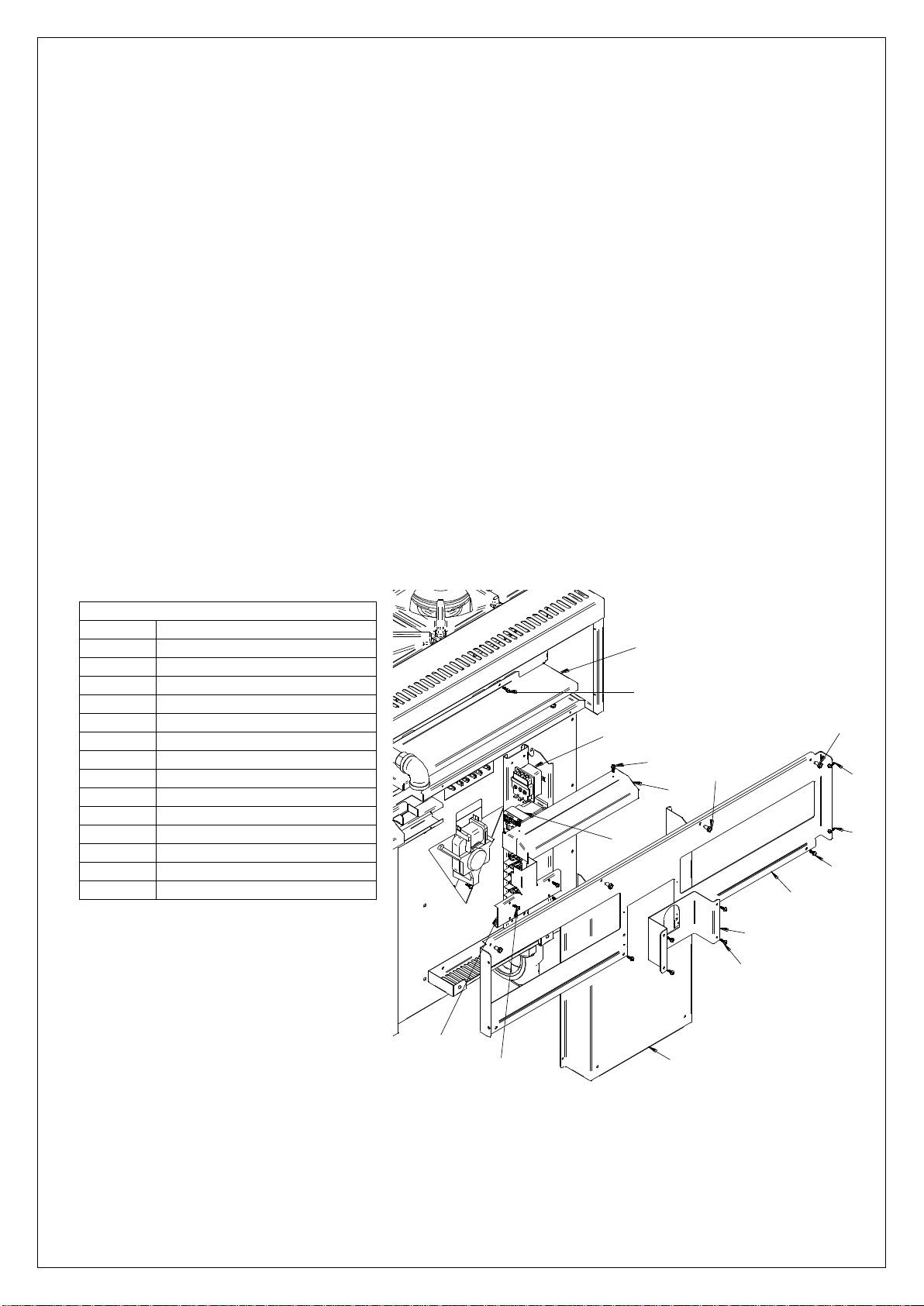
A1
A2
B1
B2
B2
B2
B3
B3
C1
D1
D2
E1
E2
F1
F2
E2
G1
H1
Control Thermostat/Fan Switch
Rear Cover Panels
Part
Description
A1
Manifold Cover
A2
Manifold Cover Screws
B1
Upper Back
B2
Upper Back Screws
B3
Flue Screws
C1
LH Rear Cover
D1
Rear Cable Cover
D2
Rear Cable Cover Screws
E1
Upper Cable Cover
E2
Upper Cable Cover Screws
F1
Cover Lid
F2
Cover Lid Screws
G1
Contactor
H1
Safety Thermostat
Remove the pan supports AA, covers, burner caps NN and burner bodies MM from the
LH side of the appliance.
From inside the oven remove the thermostat phial from its bracket and push up through the
oven roof.
Remove the fascia (see page 12). Take care not to damage the thermostat phial.
Unscrew the thermostat/fan switch from the fascia. Remove the insulated sleeving to re-use
on new thermostat.
Fit new thermostat, ensuring capillary is sleeved and routed to avoid internal electrical shorting.
Refit components in reverse order.
Safety Thermostat
Remove the pan supports AA, covers, burner caps NN and burner bodies MM from the
LH side of the appliance.
Working from the rear of the appliance, remove the rear covers A1, B1, C1, D1, E1 & F2 to
gain access to safety thermostat.
From inside the oven remove the thermostat phial from its bracket and push up through the
oven roof. Remove the insulated sleeving to re-use on new thermostat.
Remove the connections one by one and connect to new thermostat.
Unscrew the old thermostat and fit new thermostat, ensuring capillary is sleeved and routed to
avoid internal electrical shorting.
Refit components in reverse order.
IS642 ECN 4259 Page 14 of 20
Fig. 12
Page 15

Contactor
Working from the rear of the appliance, remove the rear cover C1.
Remove the connections from the contactor and connect to new contactor.
Unclip the contactor and clip new contactor into the bracket.
Refit components in reverse order.
Oven Fans
Remove the oven shelves (see page 11).
Loosen the fan guard screws and lift off the keyhole slots.
Remove the hex head nut from the centre of the fan (LH thread). Remove the fan blade.
Working from the rear of the appliance, remove the rear cover C1.
Remove the electrical connections from the appropriate motor. Remove the three securing
screws and extract the motor.
Refit components in reverse order.
IS642 ECN 4259 Page 15 of 20
Page 16
G
H
J
K
M
L
FF
WW
WW
XX
YY
FF
YY
CONVERSION
Model
Gas
Inlet Pressure
Injector
Mark
Part No.
OD8006
G20
20 mbar
GG
1.96
196
JE273 x4
J
JE275 x4
OD8007
G20
20 mbar
GG
1.96
196
JE273 x6
J
JE275 x6
OD8006
G31
37 mbar
GG
1.25
125
JE274 x4
J
JE276 x4
OD8007
G31
37 mbar
GG
1.25
125
JE274 x6
J
JE276 x6
Hob Burner Components
Part
Description
FF
Injector Housing
WW
Fixing Screws
XX
Burner Support
YY
Retaining Grub Screw
Hob Tap Components
Part
Description
G
Manifold
H
Gas tap
J
Bypass injector
K
Clamp screw
Conversion of Gas Type – Injector Changes
Hob Valve Bypass Injectors
Remove the bypass injectors J from each of the hob burner control valves H.
Replace the bypass injectors applicable to the required gas type. Screw fully
home, but do not over tighten.
Fig. 13
Hob Burner Injectors
Remove pan supports AA and lift off burner caps NN.
Undo fixing screws WW and lift up burner support XX taking not to stress both
the thermocouples and pipe work.
Remove grub screw YY, and withdraw injector housing FF and remove injector.
Replace injector applicable to gas type.
Repeat the procedure for remaining hob burners.
IS642 ECN 4259 Page 16 of 20
Fig 14
Page 17

Is there gas at the burner?Yes No
Are thermocouple connections loose?
Is the thermocouple voltage less than 15mV?
Is the valve damaged?
Check injector for blockages
Tighten connections
Replace valve
Yes
Yes
Yes
No
No
No
Replace thermocouple
Recheck system
FAULT FINDING
Please refer to the Service Help Desk number on the final page of this manual.
Burner/s will not light or stay lit
IS642 ECN 4259 Page 17 of 20
Page 18

Part number
Part description
OD8006
OD8007
BU55
Door bushes
1
2
BU72
Door bushes
1
2
BU103
Burner cap
4
6
BU104
Burner body
4
6
BU106
Injector housing
4
6
BU107
Elbow 4 6
BU108
Venturi 4 6
CA143
125mm braked swivel castors
2
2
CA145
125mm un-braked swivel castors
2
2
CO215
Contactor
1
1
DO211
Door catch assembly
1
2
EL248
Element – 3 kW
-
2
EL295
Element – 4 kW
1
-
FA12
LH Fan/Motor
-
1
FA102
RH Fan/Motor
1
1
HA77
Door handle
1
2
JE273
Hob burner injector – Natural
4
6
JE274
Hob burner injector – Propane
4
6
JE275
Hob valve low rate jet - Natural
4
6
JE276
Hob valve low rate jet – Propane
4
6
KN503
Control knob – Hob burners
4
6
KN505
Control knob – Oven thermostat
1
1
LE50
Adjustable leg - 150mm
4
4
NE46
Green Neon
1
1
NE47
Amber Neon
1
1
PA160
Cast pan supports
4
6
SE25
Door seal
2M
3M
SH112
Oven shelf
2
-
SH113
Oven shelf
-
2
SP83
Leg spanner
1
1
SR07
Oven side rack
2
2
SW58
Fan Switch
1
1
TC50
Thermocouple 750mm (hob top)
4
6
TE47
Terminal Block
1
1
TH46
Control Thermostat
1
1
TH63
Limit Thermostat
1
1
VA74
Hob burner valve
4
6
SPARE PARTS LIST
IS642 ECN 4259 Page 18 of 20
Page 19

Part Number
Description
Used on
ACCESSORIES
IS642 ECN 4259 Page 19 of 20
Page 20

Product code
All available on serial plate
Type number
Serial number
SERVICE INFORMATION
For help with the installation, maintenance and use of your Lincat equipment, please
contact our service department:
For non-UK customers, please contact your local Lincat dealer
All service work, other than routine cleaning MUST be carried out by qualified personnel
and a record kept of any remedial actions taken and at least cover the requirements of
the service schedule of this document. We cannot accept responsibility for work carried
out by other persons.
To ensure your service enquiry is handled as efficiently as possible, please tell us:
Brief details of the problem
Lincat reserve the right to carry out any work under warranty, given reasonable access to
the appliance, during normal working hours, Monday to Friday, 08:30 to 17:00.
DECLARATION
All Lincat products capable of burning gaseous fuels, satisfy the requirements of the Gas
Appliance Regulations 2016/426.
UK: 01522 875520
GUARANTEE
This unit carries a comprehensive UK mainland warranty. The guarantee is in addition to,
and does not diminish your statutory or legal rights. Contact Lincat for terms and
conditions
The guarantee does not cover:
Accidental damage, misuse or use not in accordance with the manufacturer’s
instructions
Consumable items (such as filters, glass, bulbs, slot toaster elements and door
seals.)
Damage due to incorrect installation, modification, unauthorised service work or
damage due to scale, food debris build-up, etc.
The manufacturer disclaims any liability for incidental, or consequential damages.
Attendance is based on reasonable access to the appliance to allow the authorised
personnel to carry out the warranty work.
Service calls to equipment under warranty will be carried out in accordance with the conditions
of sale. Unless otherwise specified, a maximum of 15 minutes of administrative time, not spent
directly carrying out servicing work, is provided for within the warranty. Any requirement for staff
attending the call to spend greater time than 15 minutes due to administrative requirements,
such as on health and safety risk assessments, will be chargeable at the prevailing rate.
IS642 ECN 4259 Page 20 of 20
 Loading...