

Page 1

Please make a note of your product details for
future use:
Date Purchased:_________________________
Model Number:__________________________
Serial Number:__________________________
Dealer:_________________________________
_______________________________________
Assembly Instructions
Opus 800 Floor Stands
OA8914, OA8917, OA8921, OA8934 &
OA8956
Fitting Instructions to Floor Stands
IS613 ECN4589
Page 2
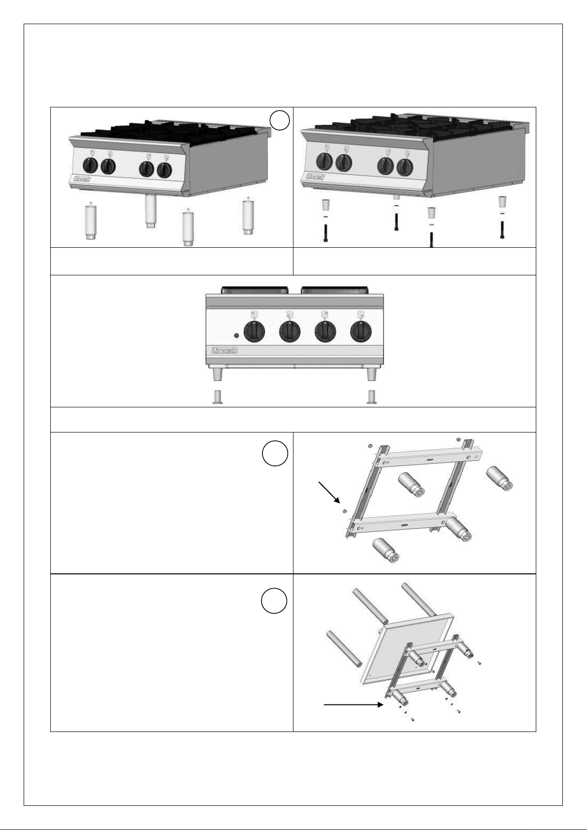
Opus 800 Floor Stand Assembly
Gas appliances only
Remove each leg from the appliance and discard
Fit plugs to the base of the appliance
Electrical appliances only
Remove the adjustable section from each leg and discard
Secure the new adjustable feet to the lower subframe as detailed using nuts N1
Note the hole positions to be used
For floor stands with castors the braked castors are
fitted to the front and the plain castors are fitted to
the rear in the same manner at the adjustable feet
Secure the sub-frame and lower shelf to the
columns as detailed
Note the radius of the shelf is to the front of the
appliance
N1
AA
BB
CC
3
2
1
Remove all protective packaging before assembling parts
IS613 ECN4589
Page 3
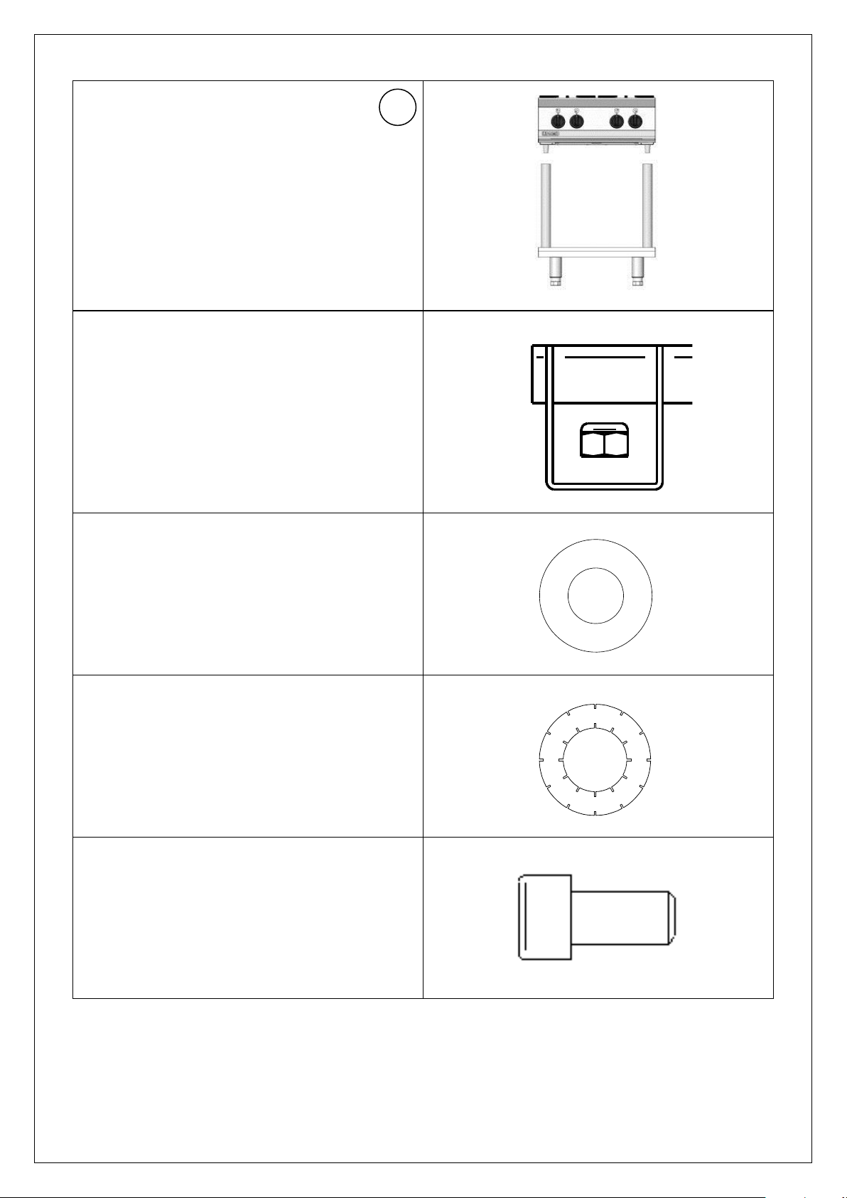
N1 – M10 self locking nut placed inside of
channel
as in instruction 2
AA – M10 Flat washer
as in instruction 3
BB – M10 Shake proof washer
as in instruction 3
CC - M10 Cap screw
as in instruction 3
Lower the appliance onto the columns
4
IS613 ECN4589
Page 4

Description
Quantity
Adjustable leg
4
Swivel Castors (where applicable) Option
4
Tubular column
4
Lower shelf
1
Sub- frame
1
M10 Shake proof washers
8
M10 Flat washers
4
M10 Self locking nut
4
M10 Cap screw - short
4
M10 Cap screw - long
4
Tapered Plugs
4
Spanner
1
Allen key
1
Assembly of Appliance to Floor Stand
Remove all protective coating from appliance and floor stand shelf
Remove loose parts to reduce lifting weight, i.e. drawers, splash backs etc.
Note: Manual handling assessment should be observed
Remove the adjustable feet from the appliance
Secure the tapered plugs to the base of the appliance – gas appliances only
Fit the new adjustable feet to the sub-frame
Using the cap screws and washers provided screw the appliance through the lower shelf
to the columns, securing fully with the allen key provided.
Place the appliance onto the assembled floor stand
Replace the loose parts, i.e. drawers, splash backs etc.
Adjust the floor stand legs to level the appliance
IS613 ECN4589
Page 5
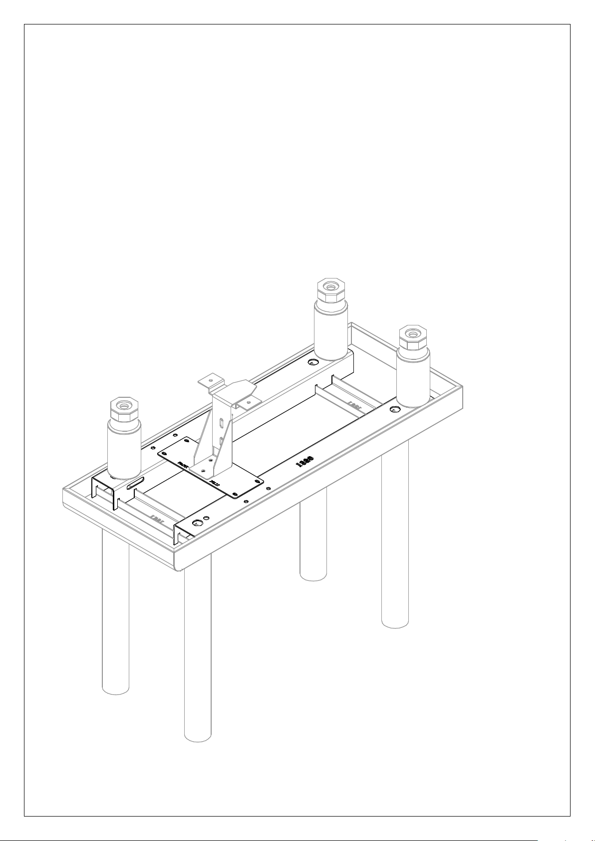
OA8934 and OA8921 Floor Stands
Additional information:
These floor stands (300mm and 400mm wide) are supplied with an SK01 stabilizer kit and
fitting instructions.
The stabilizer is attached to a cross-member plate (Part no 30122 or 30124).
This plate needs to be securely attached to the floor stand sub-frame, using the supplied
M5x16 setscrews and shakeproof washers (4 off).
Ensure that the cross-member plate is fitted with the etched text ‘Front’, to the front of the
floor stand.
IS613 ECN4589
 Loading...