

Page 1

INSTALLATION AND USER
INSTRUCTIONS
REFRIGERATED FOOD DISPLAY
BAR ACCESSORIES
IS278 ECN2970
Page 2

Page 2
Dear Customer,
Thank you for purchasing this Lincat product.
This is just one of over 300 different items of catering equipment available which is
constantly being extended and improved. Details are available from your local
distributor or direct from us.
Used for the purposes for which it is intended, and with careful maintenance as
outlined in this User Guide, your Lincat product will give years of trouble free use.
IMPORTANT INFORMATION
Please read all of the safety and operating instructions carefully
before using this product. Please pay particular attention to all
sections of this User Guide that carry warning symbols and notices.
IS278 ECN2970
Page 3
Page 3
CONTENTS
PRODUCT SPECIFICATION
Contents Page
Product specification………………………………………………….. 3
Back and Self-service Glass…………………………………….……. 4
Wall Brackets……………………………………………………………. 5
Stainless steel lid.………………………………………………………. 6
Food Display Bar Self-Service Glass – SSG4, SSG5, SSG6, SSG8, SSG10
Food Display Bar Back Service Glass – BSG4, BSG5, BSG6, BSG8, BSG10
Display Bar Wall Bracket – DBWB
Display Bar Lid – DBL4, DBL5, DBL6, DBL8, DBL10
These instructions are for your guidance and refer to the accessory ordered.
For installation and use of your Food Display Bar, follow the instructions
supplied.
IS278 ECN2970
Page 4

Page 4
BACK & SELF SERVICE GLASS
PB68
Perspex Block
GL120
Back Service Side Glass
PB68
Chromed Screw
PB68
Plastic Washer
PB68
Tube Spacer
GL479: Back Service Glass for FDB4
GL480: Back Service Glass for FDB5
GL481: Back Service Glass for FDB6
GL482: Back Service Glass for FDB8
GL483: Back Service Glass for FDB10
Remove black rubber extrusion
to fit side glass in locating slots
GL478
Self Service Side Glass
GL484: Self Service Glass for FDB4
GL485: Self Service Glass for FDB5
GL486: Self Service Glass for FDB6
GL487: Self Service Glass for FDB8
GL488: Self Service Glass for FDB10
Pack Contents:-
2 x Perspex Blocks
4 x Chromed Screws
4 x Tube Spacers
Back Service Glass
4 x Plastic Washers
2 x Side Glass Panels
1 x Main Glass Panel
1) Remove the black strips at either end of your FDB and slot in the side glass
panels. Note the orientation of Back Service side panels (shown above).
2) Fit tube spacer and washer over each chrome screw.
3) Connect a perspex block to the inside of each side glass by passing the
screw assembly through the hole in the top of the glass.
4) Line up the holes in the main glass panel with the perspex blocks and locate
with the remaining screw assemblies through the holes in either end of the
glass into the perspex blocks.
Self Service Glass
Same instructions as Back Service Glass
IS278 ECN2970
Page 5
Page 5
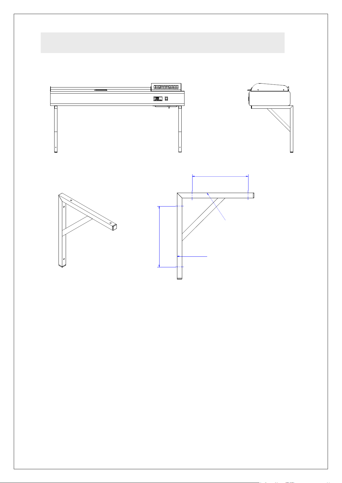
WALL BRACKETS (DBWB)
316
275
Hole centres for FPB feet
or wall mounting for FDB
Hole centres for FDB feet
or wall mounting for FPB
SPACING BETWEEN DBWB HOLE CENTRES:
FDB4 - 955mm
FDB5 - 1132mm
FDB6 - 1309mm
FDB8 - 1663mm
FDB10 - 2017mm
FPB5 - 1160mm
FPB7 - 1514mm
This accessory is suitable for both Food Display Bar and Food Preparation Bar.
1) Ensure the wall or partition is of adequate construction to take the weight of
the Food Bar.
2) Check the distance centre to centre between the feet on your Food Display
or Prep Bar and use this dimension to locate the brackets on the wall.
3) For FDB only: for each bracket drill two holes at 316 centres vertically,
suitable for M8 Rawlbolts (or equivalent – not supplied).
4) For FPB only: for each bracket drill two holes at 275 centres vertically,
suitable for M8 Rawlbolts (or equivalent – not supplied).
5) Fit the brackets to the wall.
6) Without unnecessary tilting, unscrew the feet from the Food Bar. Take care
not to trap or damage the mains cable while the appliance has no feet.
7) With assistance, lift the Food Bar onto the brackets and position so the feet
locations line up with the holes on the bracket cross bar.
8) Fix the Food Bar in position with the supplied M5 screws and washers.
9) Leave the Food Bar to stand for a minimum of 3 hours before switching on.
IS278 ECN2970
Page 6

Page 6
STAINLESS STEEL LID
Right hand hinge screwed in place
HI122
Left Hand Hinge
M5 x 20 C/sunk Head Screw
HI123
Right Hand Hinge
Lid Assembly
Hinge mounting points
Pack contents:-
1 x Stainless Steel Lid
1 x Left Hand Hinge
1 x Right Hand Hinge
4 x M5 x 20 Countersunk Head Screws
2 x M4 x 6 Dome head screws
1) Remove the protective black covers from the 4 hinge fixing holes.
2) With 2 of the M5 screws, fit the right hand hinge next to the compressor
cover.
3) With the other 2 M5 screws, fit the left hand hinge loosely so it hangs at
approximately 45º.
4) Offer up the lid against the Right hand hinge and locate the hinge pins.
5) With the lid in the raised position, lift up the Left hand hinge until located on
the lid’s hinge pins.
6) Holding the lid in place, tighten up the Left hand hinge’s screws. Fit the
hand.
7) With both hinges secure, lift the lid by the handle and lower to close.
IS278 ECN2970
 Loading...