

Page 1
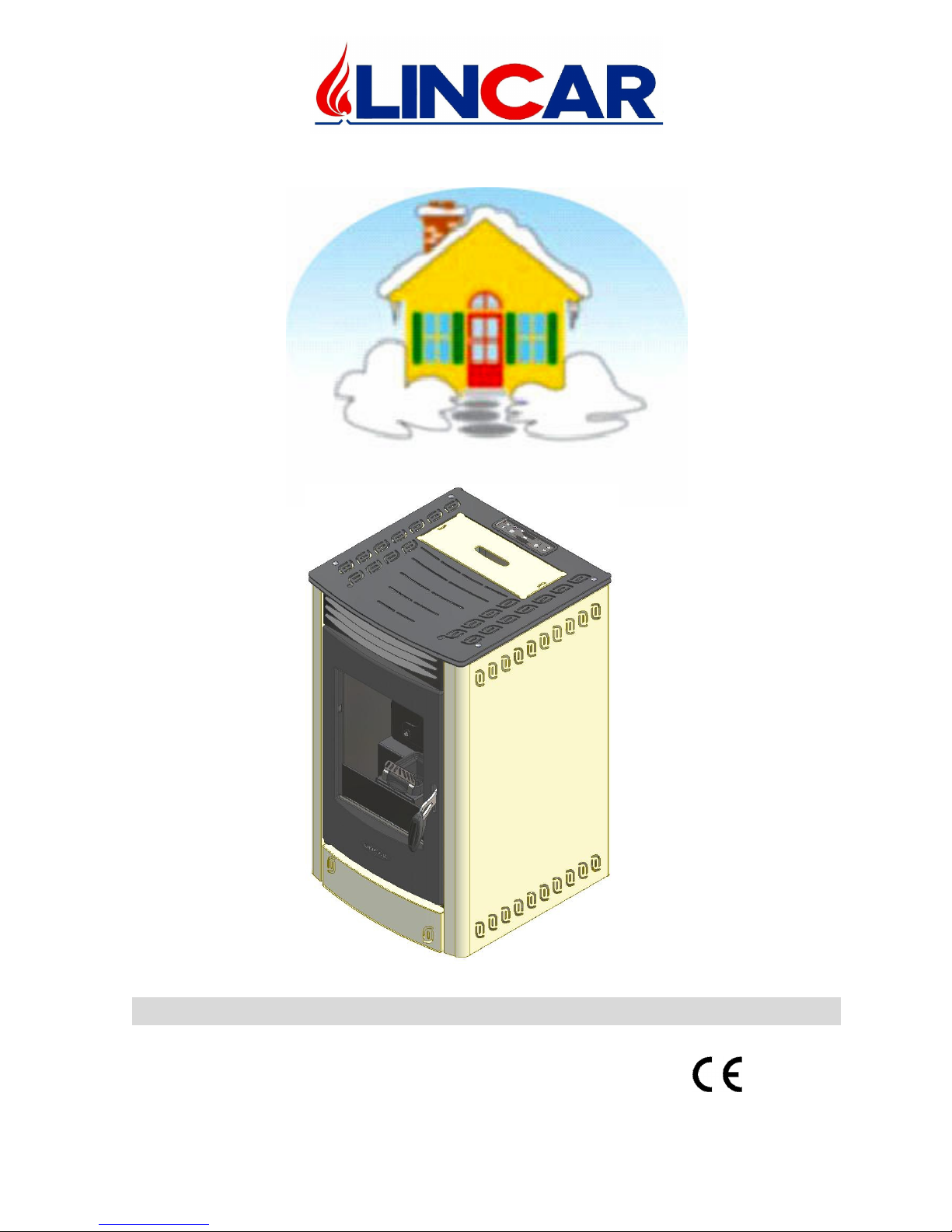
Residential space heating appliances fired by wood pellets
1/28
Perla
Mod. 514
USING INSTRUCTIONS AND MAINTENANCE
Equipments built in conformity with European Norms for the marking.
Cod. 90003133 Rev. 2
Page 2
mod. 514 GB
2/28
Dear Customer,
While we thank you for the preference you granted us, we remind you to read
carefully the present handbook because it gives You important warnings with
particular attention to the installation, utilization, maintenance and to the security of
the product in addition to condition of guarantee . To avoid it will be considered “
IMPROPER USE” of the equipment and therefore “UNCORRECTLY
UTILIZATION” with possibly of decay of the guarantee.
INDEX
Chap. Description Pag.
1 Installation
3
1.1 Normative and prescriptions 3
1.2 Preliminary operations 3
1.3 Appliance positioning 3
1.4 Connection 4
1.5 Technical details 11
2 Using
12
2.1 Important warnings 12
2.2 Combustible 12
2.3 Starting 13
2.4 Safety 20
3 Maintenance and cleaning
21
3.1 Ordinary maintenance 21
3.2 Extraordinary maintenance 22
3.3 Accessories 22
3.4 Possible failure and its solution 23
4 Technical data plate
28
Page 3

mod. 514 GB
3/28
1 INSTALLATION
RESERVED TO INSTALLER
1.1 Normative and prescriptions
• Read carefully the contents of this handbook, it contains important information and
instructions for installation, use, maintenance and product safety.
• The appliance must be installed inside an environment considered suitable for
installation and use by competent authorities. All laws, standards and regulations in force
on the installation site must be observed, especially regarding fire prevention.
• Technological connection and appliance installation must be carried out by qualify staff
authorized to release a conformity certificate according with the normative in force and
current standards.
• All the normative concerning civil town planning and/or industrial in force must be
respected inside the environment of installation of the appliance.
• All laws, standards and regulations in force on the installation site must be observed,
regarding: gas and flues, electricity, water and steam, drains and waste disposal, forced
ventilation/extraction, air intake and air conditioning. All the local and energy supplier
authorities prescriptions must be respected.
• The installation must be carried out and certified according to the normative in force
regarding installations, exhaust fumes connections, electricity, water, ventilation /
suction.
• The manufacturer disclaims all responsibility caused by no correct installation,
using, tampering, maintenance or no respect of normative in force.
1.2 Preliminary operations
• Take away the packing
• Before installation, check the appliance integrity. In case of doubt, do not use the
appliance and call the dealer.
• Packing materials is for recycle, getting it in the specify container
1.3 Appliance positioning
• The installation environment should have :
− A suitable floor for stove weight and calorific radiation, otherwise preventive
measures should be adopted. (i.e. Plate for charge distribution ).
− A suitable floor for stove calorific radiation to guarantee the building against any
fire risk.
− The stove should be installed so that gas flue, chimney and cleaning could be easily
done.
− A minimal distance from flammable materials ( Security Distances)
− A suitable ventilation as normative in force.
FLOOR PROTECTION
• The equipment has to be put on a refractory surface. In case of flammable floor (
moquette, parquet ..) it’s necessary to put a refractory base ( stainless steel, ceramic etc )
with the following dimensions :
− Hold up in front ≥ 500 mm;
− Hold up lateral ≥ 300 mm;
− Hold up back ≥ 100 mm
Page 4
mod. 514 GB
4/28
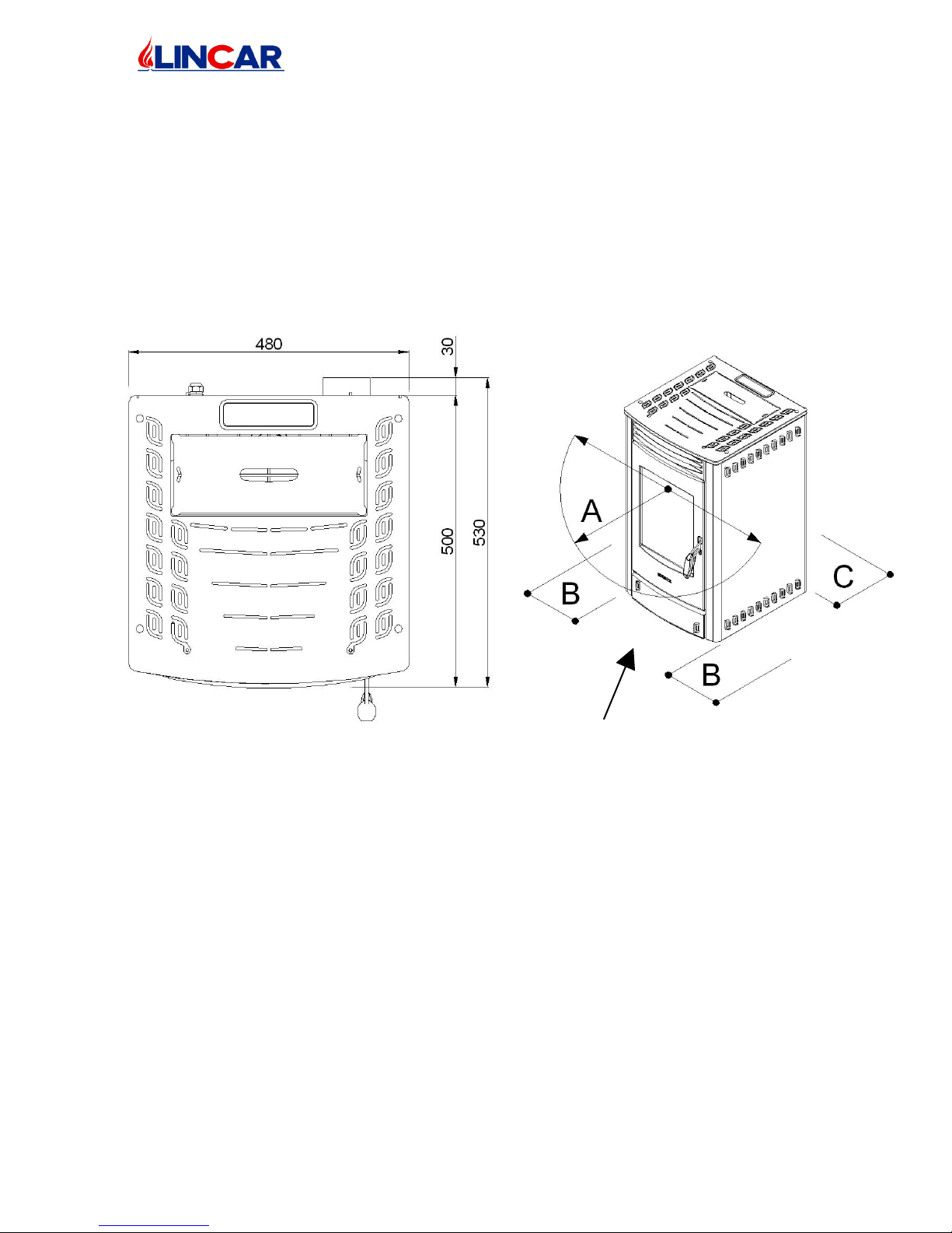
Always measure from external
equipment surface
SECURITY DISTANCES
• From flammable object :
− A > 400 mm B > 100 mm C > 100 mm
• From flammable object and from principal wall in rein forced concrete :
− A > 800 mm B > 200 mm C > 200 mm
• The minimal distance between the stove and every object around it is 1 mt
1.4 Connection
• Before connection check the technical data reported in the technical plate and control
that they correspond to the ones required in the order.
• All heating biomass equipments especially wood and pellet stove have to evacuate the
combustion products in a flue, built in conformity with the normative in force
• The following instructions describe „ informations for a good installation „ and refer to a
normative in force but they are not to be consider exhaustive for installations laws
Page 5

mod. 514 GB
5/28
CHIMNEY OR FLUE
• The chimney or flue should have the following characteristics:
− It’s advisable to read, follow and respect what indicated in the paragraphe 1.1
− Good sel of combustion products, impermeable and completely insulated as
normative condiction
− The flue has to be built with raw material suitable for normal mechanical stress,
warmth, action of combustion products and its condenses
− The flow has to be vertical with deflections no hihgher that 45°
− A right distance from combustible or flammable material, insulated with an air
cavity or right insulator
− Internal round section, the square or rectangular section should have round corner
with a ray not less than 20 mm
− Internal section should be constant, free and indipendent
− Rectangluar section with sides ration max of 1,5
− All manufacturer instruction should be respected concerning the section and the
building characteristic of the chimney or flue. For particular section, deviation of
section or path it will be necessary a complete inspection of exhaust fumes system.
− It‘s advisable that the flue should be supplied by a „chamber „ for solid material and
condenses collection, placed under the flue throat and easy to reach and to open. It
should be also supplied by a completely seal „little door“ for inspection.
− In case of fire of chimney or flue, employ the right system to soffocate the flames
and call for firefighter.
EQUIPMENT CONNECTION TO FLUE AND EVACUATION OF COMBUSTION
PRODUCTS
• It’s advisable to read, follow and respect what indicated in the paragraphe 1.1
• The flue should receive the exhaust fumes from an only heating equipment
• It’s possible to realise an equipment composed from chimney and cooking oven with an
only exhaust fumes point head the chimney, for which the manufactures has to provide
the building characteristics of exhaust fumes channel
• It’s prohibited to connect in the same flue, the heating equipment and the suction hood
• It’s prohibited to connect the exhaust pipe head closed space even if it is in open air
• The direct exhaust fumes has to be done ahead roof and the exhaust pipe should have the
above characteristics.
Page 6
mod. 514 GB
6/28
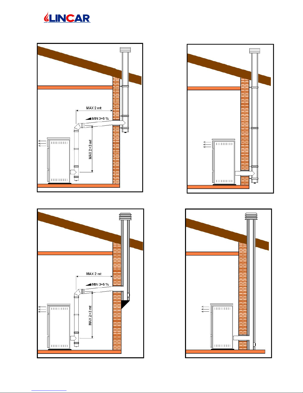
Hereby some suggested schemes regarding the exhaust of the combustion products.
Insulated Flue Insulated Flue
Masonry insulated flue Masonry insulated flue
Page 7
mod. 514 GB
7/28
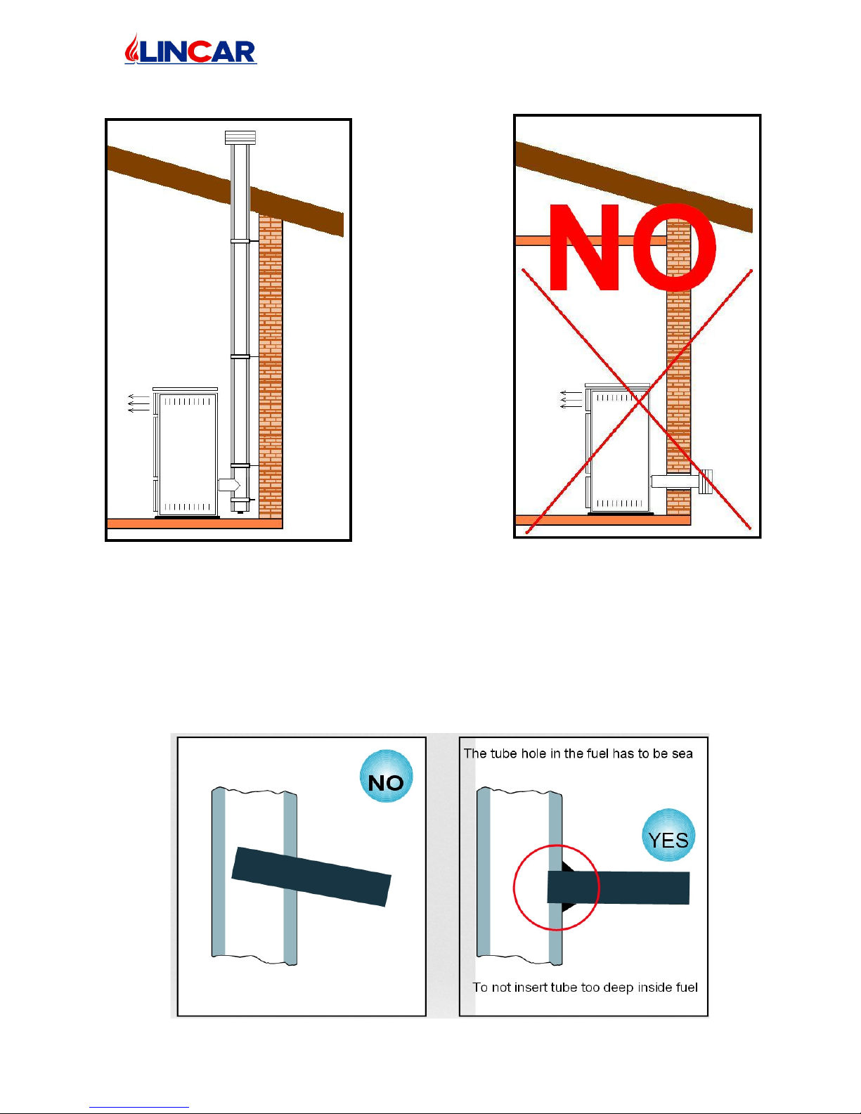
Insulated Flue
CONNECTION TO FLUE
• The connect the heating equipment to the flue / chimney checking that the exhaust pipe
don’t take up the free section of flue.
• Employ only tubes supplied by seal gasket.
• Limitate the use of horizontal tubes ( max 2 mt ) and curves.
Page 8
mod. 514 GB
8/28
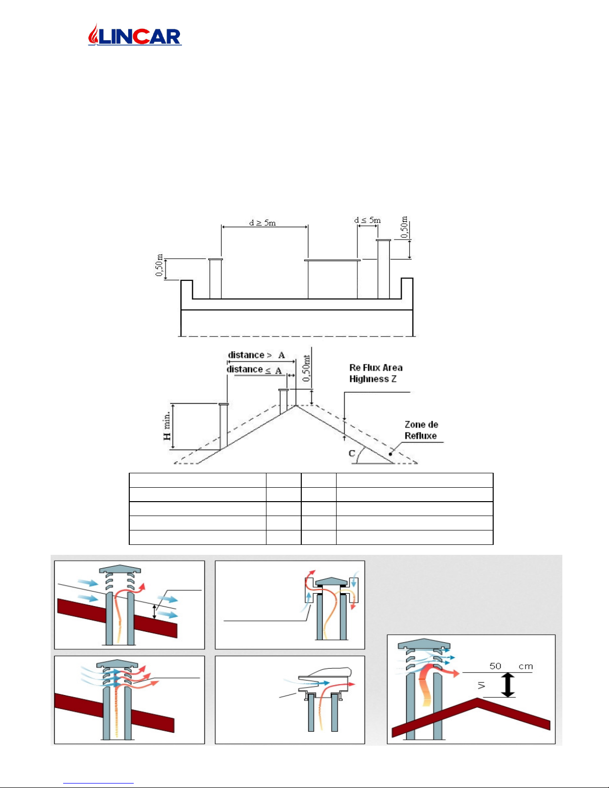
CHIMNEY CAP
• The chimney cap should have the following characteristics:
− It’s advisable to read, follow and respect what indicated in the paragraphe 1.1
− Internal section equivalent with the chimney one
− Exhaust section exit not lower to the double of the chimney internal one
− Built in a way to avoid rain, snow or external body entrance, to ensure the right exit
of combustion products with any type of wind
− Positioned to guarantee the right fumes dispersion especially out of re-flux area.
This area has several dimensions and conformations in function of inclination
corner of the covering so it’s necessary to apply the minimal highness as indicated
in the following tables:
Inclination Roof C (°) A H Re Flux Area Highness Z (m)
15 1,85 1,00 0,50
30 1,50 1,30 0,80
45 1,30 2,00 1,50
60 1,20 2,50 2,10
Re-flux
area
Chimney pot
wind damping
Chimney
Pot Wind
Damping
Revolving
chimney pot
for strong
horizontal
wind
Page 9
mod. 514 GB
9/28
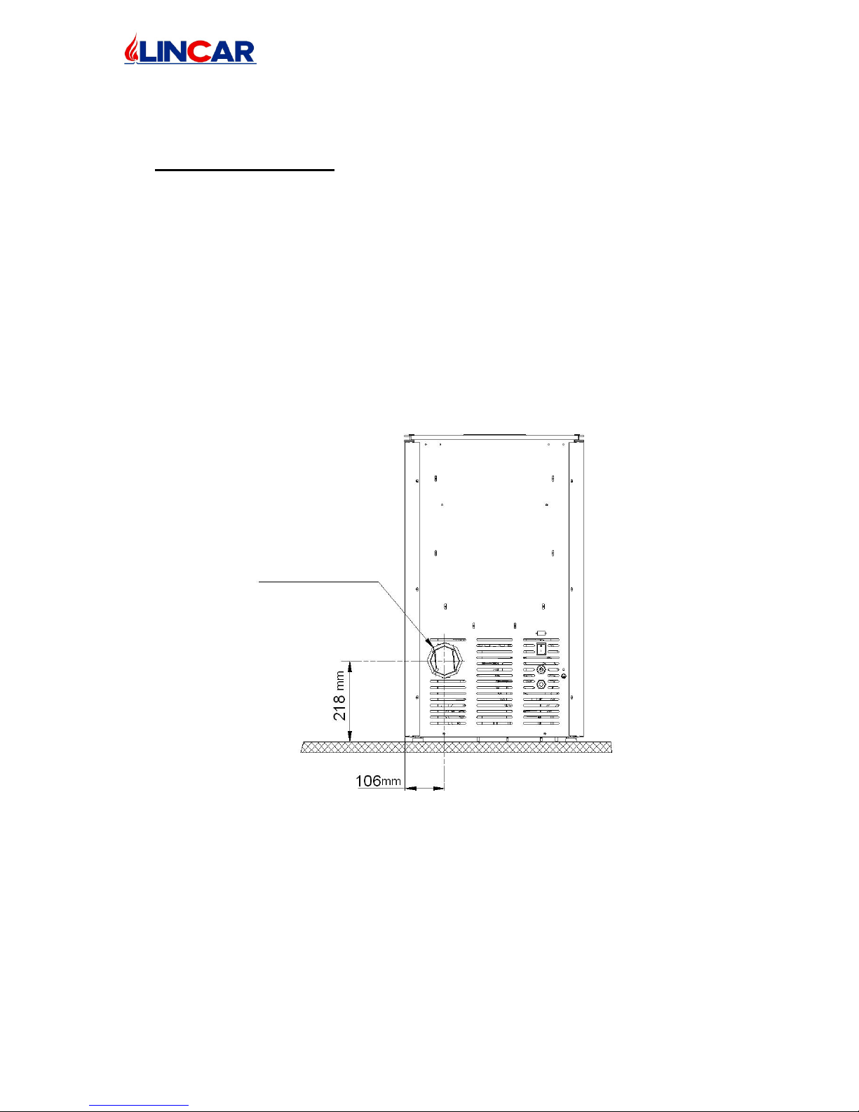
DIMENSIONS FOR EXAUST TUBE CONNECTION AND AIR SUCTION
• Attention to stove model.
• In case that it‘s necessary to make hole in wall for exhaust fume, proceed as follows :
− Measure and draw with real dimension on the wall the points for stove connection;
− Realize the hole on the wall.
− Connect the stove to the flue with the tube for exhaust fume.
− In case that the exhaust tube has a connection position not horizontal (f.e.up
connection ) it’s necessary to maintain a security distance of exhaust tube from wall
of 100 mm
DIAMETER EXHAUST
Ø80
Page 10

mod. 514 GB
10/28
ELECTRICAL CONNECTION
• The appliance is equipped with an electrical cable H05RR-F 3x0.75 mm² having an
European plug. It is a type “Y” connection and therefore any replacement of the cable
must be carried out by a qualified staff only. Feeding 1N 230V AC 50Hz. The electrical
cable should be disposed in such a way to avoid any contact with hot and sharp parts.
• The appliance should be connected with a grounding system.
FEED AIR COMBUSTION DIRECT FROM ENVIRONMENT
• It’s advisable to read, follow and respect what indicated in the paragraphe 1.1
• The equipment should have the necessary air for combustion, supplied by external air
intake.
• The air intake should have the following characteristics :
a) Total free section min 200 cm²;
b) Connected directly with installation environment ;
c) Protected with grate or lath ( attention to not reduce the min. section required on
point a ) and placed so that to avoid obstruction.
• The air inflow can be also supplied from the adjacent room but the air intake should be
always free and connecter ahead outside. No chimney or suction hood should be present
in the environment of installation or into the nears ones.
• Inside the adjacent room the air intake should have the characteristics required in letter a
and c .
• The adjacent room can not be use as garage, warehouse of combustible material etc..
NOTE: The air inflow whole must be placed at the low.
NOTE : Extractor fans when operating in the same room or space as the appliance may cause
problems.
NOTE :The installation room should not be put in pressure by other appliances such as
suction hoods, chimneys, evacuation flues, present in the room itself or in the adjacent rooms,
which are in communication.
Page 11
mod. 514 GB
11/28
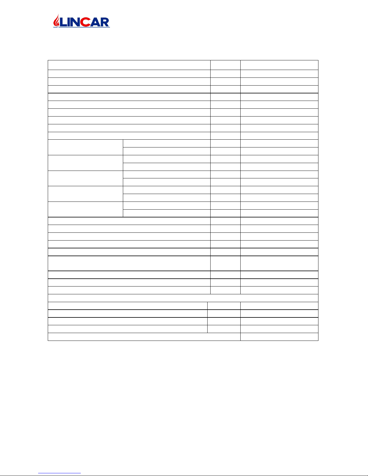
1.5 TECHNICAL DETAILS
DESCRIPTION
Perla 514
WIDTH mm 480
DEPHT mm 500
HEIGHT mm 825
EQUIPMENT WEIGHT kg 82
Ø DIAMETER EXHAUST FUME mm 80
GLOBAL HEAT INPUT kW 6.8
GLOBAL REDUCED HEAT INPUT kW 3.4
NOMINAL POWER OUTPUT kW 5.5
REDUCED POWER OUTPUT kW 3.0
EMISSION OF CO : (AT
13% OXYGEN CONTENT)
NOMINAL POWER OUTPUT
% 0.0126
REDUCED POWER OUTPUT
% 0.0178
EMISSION OF CO
2 :
NOMINAL POWER OUTPUT
% 7.93
REDUCED POWER OUTPUT
% 6.49
ENERGY EFFICIENCY:
NOMINAL POWER OUTPUT
% 81.0
REDUCED POWER OUTPUT
% 87.2
FLUE GAS TEMPERATURE:
NOMINAL POWER OUTPUT
°C 238.7
REDUCED POWER OUTPUT
°C 143.6
FUME CHIMNEY
QUANTITY (m):
NOMINAL POWER OUTPUT
g/s 5.5
REDUCED POWER OUTPUT
g/s 3.5
COMBUSTIBLE CONSUMPTION MAX kg/h 1.42
COMBUSTIBLE CONSUMPTION MIN kg/h 0.72
AUTONOMY MIN / MAX h 11.6 / 23.0
HEATING VOLUME INSULATION FAVOURABLE m3 140
HEATING VOLUME INSULATION UNFAVOURABLE m3 75
DEPRESSION CHIMNEY IN TEST
P.NOMINAL / P.REDUCED
Pa
10.0 / 9.5
DEPRESSION CHIMNEY MIN. Pa > 0
DEPRESSION CHIMNEY MAX. Pa < 20
WOOD-PELLETS LOADING MAX kg 16.5
ELECTRICAL ABSORPTION
VOLTAGE / FREQUENCY V.a.c./Hz 230 / 50
ELECTRICAL INPUT POWER DURING
IGNITION
W 340
ELECTRICAL INPUT
POWER DURING FUNCTIONNING
W 100
FUSE (5X20) A 4T
TYPE OF COMBUSTIBLE Wood Pellets Ø6 mm
Page 12

mod. 514 GB
12/28
2 USING - RESERVED TO USER
2.1 Important warnings
• To read carefully this section’s instruction which are very important for use, maintenance
and appliance safety.
• This handbook has to be ridden completely, in case of lack it can be consider an
improper use of the equipment so a not right use of it.
• To take care of this handbook to use it every time it’s necessary.
• The appliance illustrated in this handbook must be employed only from qualify staff.
• The appliance should not be employ as incinerator.
• The appliance functioning, create high temperature on some internal and external
surfaces, with which user could get in touch so it’s necessary the maximum attention!
• This appliance can not be employed by people ( also child ) who have not a sufficient
physic and mental capacities or with no sufficient experience or knowledge. The
appliance should be employed only by person who can be responsible for its safety.
• The appliance should be consider as active area of thermical exchange with warmth
surfaces so it’s necessary to be cautious to avoid the direct contact with children, animals
etc ….
• Employ the specific utensil to open the fire door.
• The right stove functioning is with closed door, if the fire door window is broken and / or
damaged or in case of bad functioning, the stove can not be lighted till the problem has
be solved.
• The operation of the machine must always happen under surveillance.
• To disconnect the appliance in case of breakdown or bad functioning, from electrical
system.
• Every maintenance operation, every repairs or substitution, should be done from qualify
staff or assistance centre. Use only original spare parts.
• To not tamper the appliance.
• Do not obstruct air vents or heat dissipation openings.
• Do not use the appliance as a bearing instruction or as a staircase.
• Never introduce manually the pellet into the burner basket.
• Do not put other materials than pellet into its container.
• Do not touch the appliance with moist or wet hands, it is an electrical appliance.
• Any responsibility arising from an incorrect use of the appliance is totally at charge of
the user and relieve LINCAR S.p.A. from all and any responsibilities.
• Every local , National or European normative in force has to be respected during the
installation.
• The safety distances from flammable material has to be observed and all the
prescriptions contained in chapter 1.
2.2 Combustible
• The combustible to employ is :
GOOD QUALITY WOOD PELLETS
Calorific power kWh/kg 4.8÷5.2
Density kg/m3 650
Water contents % Max 8% of weight
Ash percentage % Max 1% of weight
Diameter mm 5 ÷ 6,5
Lenght mm 20 ÷ 30
Contents % 100% no treatise wood with percentage bark max 5%
Page 13

mod. 514 GB
13/28
• It’s prohibited to use solid combustible as straw, mais, hazelnut, pinecone or other
different from indicated in this handbook. We recommend to employ always certify
combustible of Your dealers ( as table here below ).
INFORMATION ABOUT PELLETS
• Pellets is made by wood rejection that came from saw-mill or planning industry and
wood fragment of forest industry. This raw material is shattered, dried up, crushed, with
some bound material till up to become the pellet combustible.
PELLETS PRESERVATION
• Pellet has to be kept in a dry and clean environment.
2.3 Starting
• The appliance should set at work only after having completed the following operations:
complete assembling, connection to exhaust fumes duct and to the heating plant. A new
stove needs to complete the drying process of the paint. During the first heatings you can
notice the following situations:
- During the first ignitions the appliance may exhale bad smell. We suggest a good
aeration of the room till bad smells have been eliminated.
- The complete drying process will be obtained after some heating operations
WOOD PELLET LOADING
• Be careful during wood pellet loading operation ! The pellet bag should not touch the
warm stove.
• Be careful that no external corps enter into the pellet tank as pieces of bag, wood pieces
or other that can obstruct the screw feeder and damage it.
• The wood pellet loading should be done at the top, after having removed the cover.
During stove functioning, it’s advisable to employ the specific glove because the stove
surface could reach high temperature.
• To check always the level of combustible in the combustible tank and check-it often, to
avoid the light off of the stove.
• The cover tank has should be always closed, except during pellet loading.
• Tank Pellets capacity : information on Technical details part
Page 14
mod. 514 GB
14/28
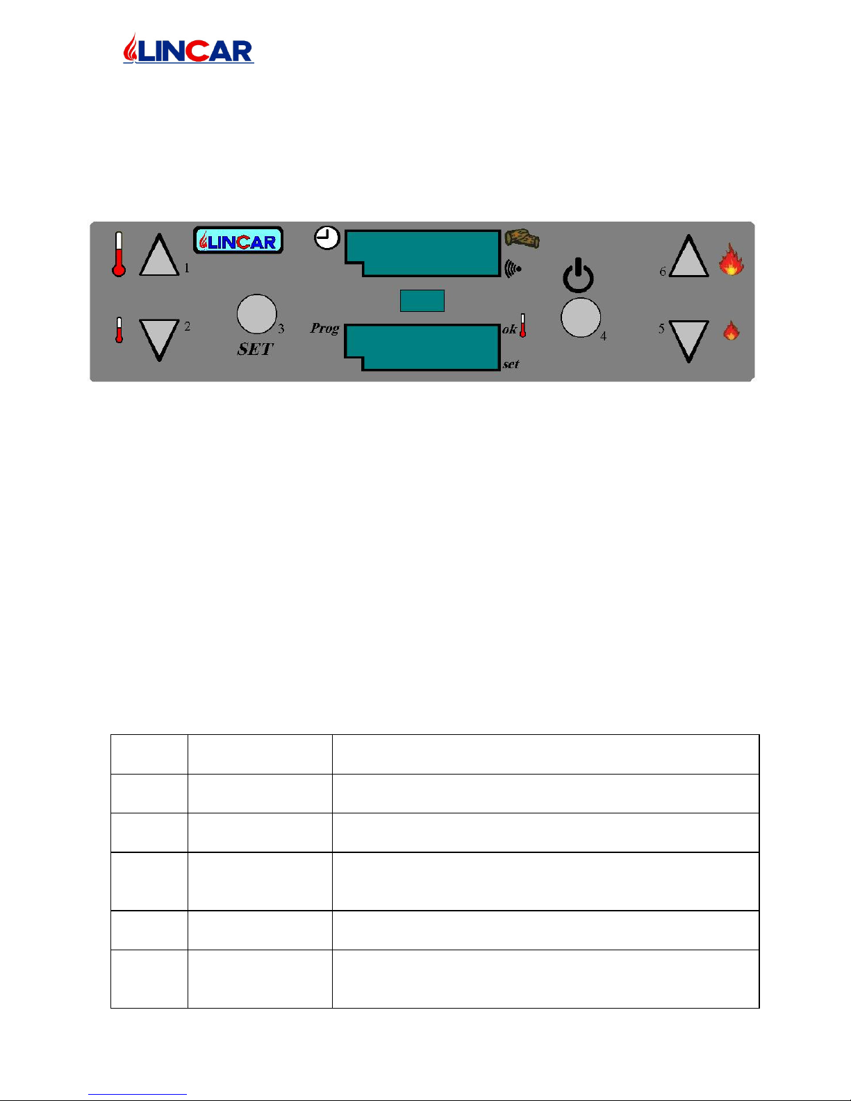
SWITCH CONTROL PANEL FUNCTION
• The Pellet Stove is equipped with an electronic card, installed inside appliance, who
receives the function instructions from the control panel with a display who shows the
data. Pushing different button, it’s possible to select different functions
BUTTON FUNCTION DESCRIPTION
Button 1 and 2 ……………. - To high and to low selected room temperature, to modify the
data value which is programming.
Button 3(SET) ………… - To access into programs ( temperature and time ).
- To confirm select data.
Button 4 ……………...... - To light / To turn off the stove and to exit from programs.
Button 5 and 6 …………… - To high and to low functioning stove power.
IGNITION CYCLE
• The ignition cycle last normally 15 min and it’s composed by 4 different phases which
will be visualized on display with the following marks:
− “FAN ACC” = Glow – plug pre-heating phase
− “LOAD WOOD” = Pellets Loading phase
−
“FIRE ON” = Combustion Pellets phase
−
“ON.../ECO” = Power function phase
Display
Equipement
phase
Explication
FAn
Acc
Heating ignition
blow plug.
Equipment ignition phase, the equipment is in a phase of
ignition blow plug first heating.
LoAd
Wood
Ignition
equipment phase.
The equipment start to feed the burner with the pellets, it
control the combustible ignition through the fumes feeler.
FirE
on
Ignition
equipment phase.
At combustible ignition ( on right burner side ) the
equipment wait for complete burner ignition in order to start
the power function.
ON
1...5
Power function. The equipment is functioning on selected power till the
required temperature is reached.
Eco
18°...
24°
Economy
Function.
At programmed temperature reaching, the equipment
functions at min. power (Economy) till the environment
temperature doesn’t lower.
Page 15

mod. 514 GB
15/28
StoP
FirE
Foyer cleaning. The equipment is executing the foyer cleaning, the pellets
feed is on min. and motor for exhaust fumes is on max.
Off
09:32
−
Equipment
Stop.
− Equipment
Rest.
−
The Stop button has been pushed and the equipment start
the turning off cycle.
− The equipment is turn off
1ST IGNITION OR IGNITION AFTER PELLET TANK EMPTYING
• Verify that the pellet tank is full, the equipment is connected to the socket and the back
switch is on position 1 ( display control panel is lighted ). During the 1st equipment
ignition, the loading member ( screw feeder ) is not load so it’s possible that the
equipment will not complete all ignition phases and it raise the alarm ( alar – no Acc ) :
it’s necessary to repeat one or more time the following:
1 Push for several seconds the button nr. 4 of control panel – If the initials “alar – No
acc “ will appear, carry on as point 2 or wait the initials “On” or “Eco” on display,
to indicate the function power phase;
2 Turn off the equipment, pushing button 4 for several seconds, on panel control;
3 Remove the current through the back button 0 – 1;
4 Remove pellets from burner tank;
5 Recover the current through the back button;
6 Repeat from point 1.
IGNITION – NORMAL CYCLE
• To check the pellets quantity inside tank than check that the combustion room and the
basket ( with all its holes ) are clean form impurity. After basket cleaning, to insert it
again checking that the big hole correspond to the screw feeder tube placed on right of
combustion room that push for several minutes the button nr. 4 of panel control.
POWER REGULATION
• It’s possible to select the calorific power between the button 5-6 ( on 1…….on 5 ) from
3.0 to 5.5 kW. The optimal regulation of singular function is automatic inside equipment.
It’s not possible to modify the calorific power when the stove is in “Eco” modality
( it’s go pass the selected temperature environment).
TO BLOCK/UNBLOCK THE PANEL
• It’s possible to block the panel equipment to avoid the use from no technical people. To
activate or deactivate the panel block, keep pressed the button 2 at least 10 sec. the
display signal “bloc” if the panel is blocked, “norm” if the panel is unblocked.
Page 16
mod. 514 GB
16/28
display day
oFF Program OFF
dAY 1 Monday
dAY 2 Tuesdays
dAY 3 Wednesday
dAY 4 Thursday
dAY 5 Friday
dAY 6 Saturday
dAY 7 Sunday
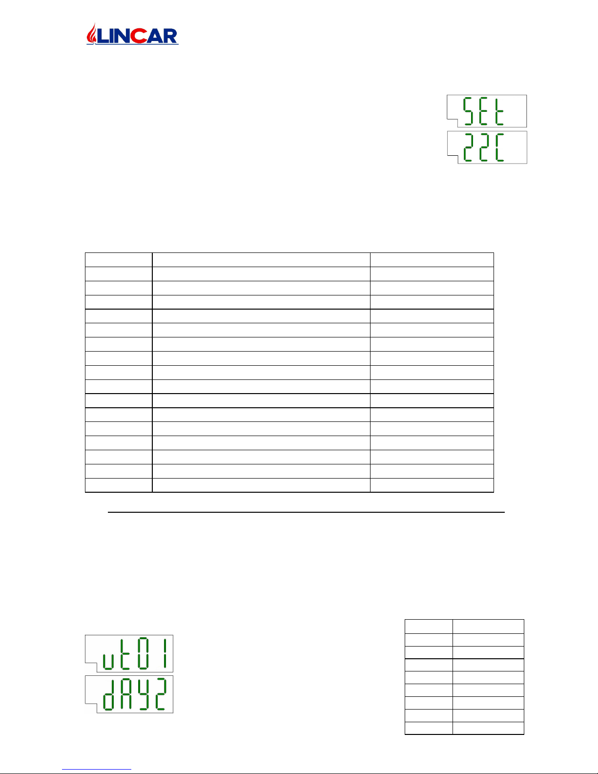
ROOM TEMPERATURE
To program the desired room temperature, push the button 3 (SET),
the display will signal the modality SET and it visualize the
environment temperature programmed; button 1 and 2 to select the
new temperature, at the program finish, wait several second without
push any button till on display the initials SET disappears.
• The stove is equipped with a temperature feeler to find the
environment temperature so when the stove will reach the selected temperature, the
initial ECO will appear on display and the stove is in economy function that corresponds
to power 1.
THERMOSTAT – TIME
Parameter Description Range
ut 01 Week day off – dAY7
ut 02 Local time 00 – 23
ut 03 Min. of local time 00 – 59
ut 04 For technicians 00 – P5
ut 05 Starting time 1st cycle 00:00 – 23:50 (OFF)
ut 06 Blowing out time 1st cycle 00:00 – 23:50 (OFF)
ut 07 Activation/Deactivation program 1st cycle on(1..7) – off (1..7)
ut 08 Starting time 2nd cycle 00:00 – 23:50 (OFF)
ut 09 Blowing out time 2nd cycle 00:00 – 23:50 (OFF)
ut 10 Activation/Deactivation program 2nd t cycle
on(1..7) – off (1..7)
ut 11 Starting time 3rd cycle 00:00 – 23:50 (OFF)
ut 12 Blowing out time 3rd cycle 00:00 – 23:50 (OFF)
ut 13 Activation/Deactivation program 3rd cycle on(1..7) – off (1..7)
ut 14 Starting time 4th cycle 00:00 – 23:50 (OFF)
ut 15 Blowing out time 4th cycle 00:00 – 23:50 (OFF)
ut 16 Activation/Deactivation program 4th cycle on(1..7) – off (1..7)
A The thermostat time to active and to program the automatic equipment function time. It’s
possible to program till 4 automatic equipment ignitions / turning off during a day.
Every parameters group to program included :
− Ignition Time;
− Turning off time;
− To select days during the program should be active .
Attention !! To go out program, push the button 4 in every point !
B PROGRAM / CHECK WEEK DAY PROGRAM. Push the button 3 (SET) till on
display appears the initials :
Using button 1 and 2 to select the day
and the button 3 (SET) to confirm.
Page 17
mod. 514 GB
17/28
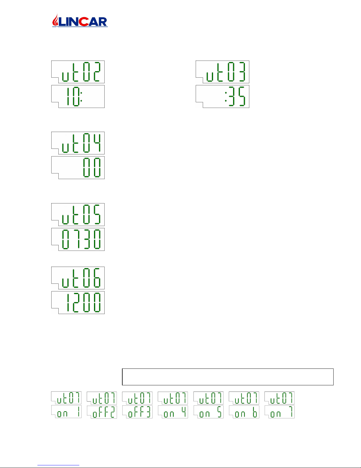
C PROGRAM / HOUR CHECK. Push the button 3 (SET) till on display appears the
initials :
For hour For minutes
Push the button 1 and 2 to program with right data and push the button 3 (SET) to
confirm.
D Only for technical program, reserved to technician and qualify
staff. Keep the initials on 00, push the button 3 (SET) .
E TO PROGRAM FIRST IGNITION HOUR / TURNING OFF
Push the button 3 (SET) till on display appears the initials:
Use the button 1 and 2 to program the
ignition hour desired, and the Button 3
(SET) to confirm.
To set up OFF to not have an ignition time.
F Push the button 3 (SET) till on display appears the initials:
Use the button 1 and 2 to program the
turning off hour desired, and the Button
3 (SET) to confirm.
To set up OFF to not have a switch off time.
G AUTOMATIC IGNITION. It’s necessary to select the week’s day during the automatic
ignition should be programmed then push the button 3(SET) till on display appears the
initials :
Button 1 = to visual the week day (on/off 1..7).
Button 2 = to modify the programmed condition from On to Off or the contrary
ON = Activated
OFF = Deactivated
In the enclosed example : the program is activated on Monday, Thursday, Friday,
Saturday and Sunday.
ATTENTION
!!
To conf
irm
with the button
3 (SET) ONLY AFTER
having programmed every week’s day with the button 1 and 2.
Page 18
mod. 514 GB
18/28
H To carry out the following program Ignition / Turning Off go on as points E-F-G. See
table 1 to identify the correspondent data ut08-ut09-ut10, ut11-ut12-ut13, ut14-ut15-
ut16 (vedi tabella “Cronotermostato”).
Attention !! To go out program, push the button 4 in every point.
I Attention to possible overlapping about ignition / turning off program’s hour; a wrong
program means that the stove will start / turn off when it’s necessary that it’s light on
(or the contrary) so we recommend to not program in the same day new ignition before
the turning off hour of precedent cycle.
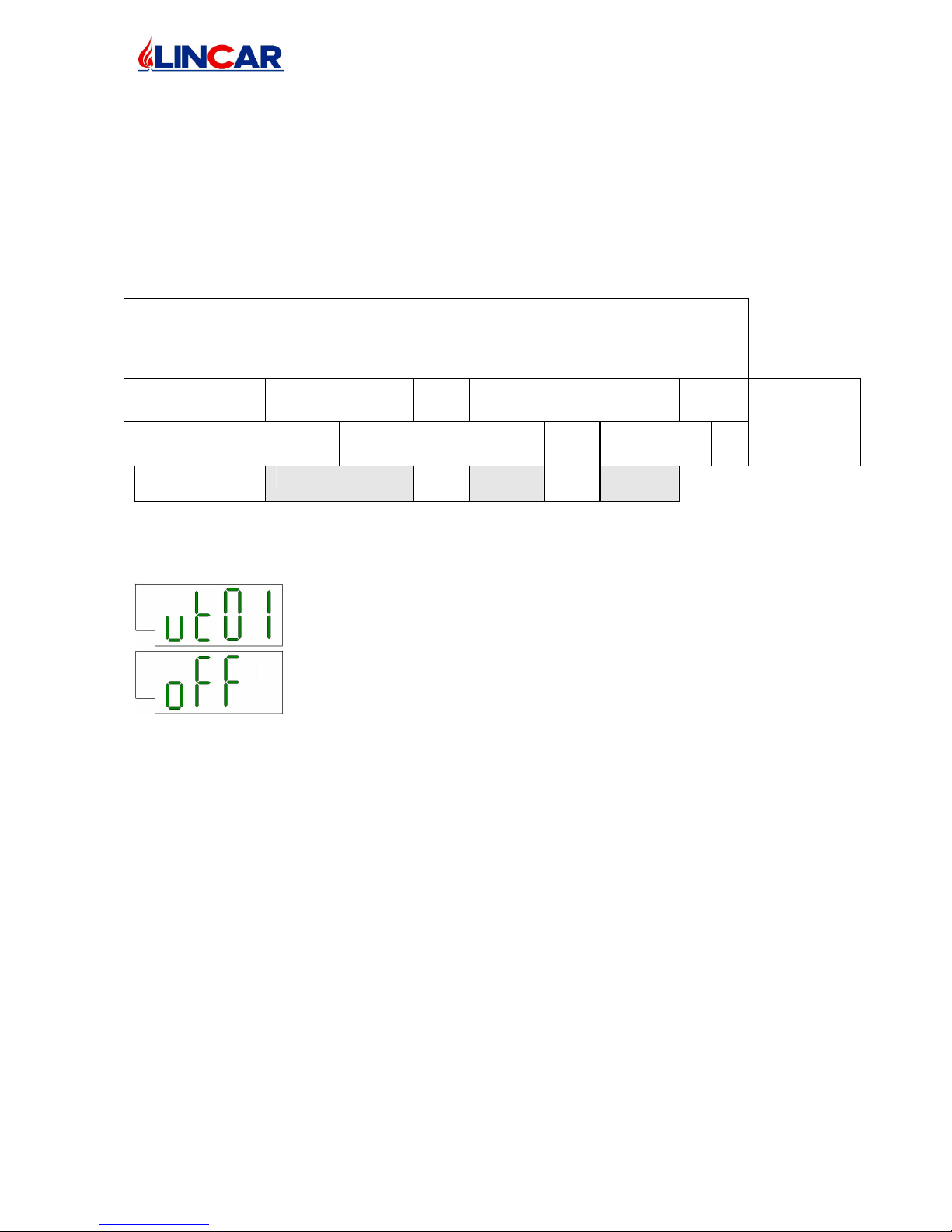
00:00
01:00
02:00
03:00
04:00
05:00
06:00
07:00
08:00
09:00
10:00
11:00
12:00
13:00
14:00
15:00
16:00
17:00
18:00
19:00
20:00
21:00
22:00
23:00
24:00
Program 1°
cycle
Program 2°cycle Saturday
Saturday
Program 3° cycle Program
4° cycle
Functioning
Funct.
Funct.
Effective function due to programs overlapping
L
STOVE USE ON MANUAL MODALITY
To employ the stove on manual modality without delete the recorded
program, go on as point B and program ut01 – oFF .
To active again all programs to select ut01 and the current day.
It’s possible to carry out manual Ignition/ Turning Off even with active programs which will
start up and turn off during predetermined hour at the same. To use the stove only on manual
modality, go on as point L.
It’s possible to have the equipment that start to a set hour but the switching off is depending
on user : to have this program, set the time of switch off (point F) on value OFF, any
switching off time is selected and the user will decide the equipment switch off, pushing the
button 4 (start/turn off).
On the contrary, the equipment could not have a time of ignition but a set hour to switch off :
to have this program, set the start hour (point E) on value OFF, so any start time will be
present and the user could light up the equipment when he wants, pushing the button 4
(start/turn off), when the switch off time is reached, the equipment will switch off
automatically.
EQUIPMENT TURNING OFF
• Pushing for several time the button nr. 4 on control panel, the turning off operation start
up, the screw feeder motor is deactivated and the pellets is no more feed. The two fans (
gas combustion fan and fan for air convection ) will function again for some minutes till
the exhaust gas temperature lower then they turn of.
Page 19

mod. 514 GB
19/28
COMBUSTION REGULATIONS
Sometimes changing the pellets, in sight of the several types of wood pellets presents on the
market, some modifications on equipment combustion could appear. An evident signal of a
wrong combustion is the excessive or lack quantity of pellets in then burner during the normal
functioning. It’s possible to make some regulations on the equipment combustion. The basket
– burner during the normal combustion should contain combustible from 1/3 till a middle of
its capacity, if necessary, to carry on to some regulations, please follows the following points :
a. To check the equipment functioning and check if in the burner basket, the pellets
accumulate till the complete fill up of its or if the burner basket emptied till the flame
light off.
b. Push several times the button 3(SET) to visualize on the top part of the display ut40
c. Push several times the button 1 to visualize on the lower part of the display the num.33
d. Push the button 3(SET), the display visualize “corr” in the top part and a number in
the lower part.
e. Employing the button 1 and 2 to modify the number on the lower display as indicated
in the enclosed schedule, to increase the pellets quantity increase the value, to reduce
the pellets quantity reduce the value.
ATTENTION ! We recommend to make these modifications increasing/reducing the initial
value little by little ( only one number ), checking the equipment functioning for 1 or 2 days
even taking care to keep clean the basket burner, only after this checking period You can
modify again the regulation.
Increase the pellets quantity Reduce the pellets quantity
9 8 7 6 5 4 3 2 1 0 -1 -2 -3 -4 -5 -6 -7 -8 -9
STAND-BY
The STAND-BY status means that when the equipment reach the ambiance temperature set
up, the equipment turn off to start again automatically when a lower temperature is taken.
This is the procedure to follow :
- Push several times the button 3(SET) to visualize on the top part of the display ut04
- Push several times the button 1 to visualize on the lower part of the display the
numb.99
- Push the button 3(SET), the display visualize “StAn by” in the top part and “OFF” in
the lower part.
- Program the °C (es 1°-2° ecc) the temperature value to activate the STAND-BY
modality. Program OFF to deactivate the STAND-BY modality.
- The stove will function in STAND-BY modality so when the temperature ambiance is
reached as set out °C in the preceding point : EX : it’s set up 2° to preceding point and
supposing to have set the equipment to 22°C the modality STAND-BY will activate
when the 24°C is reached (22° + 2°) The equipment will light on when the ambiance
temperature will be lower than it set up, in this case 22°C.
IMPORTANT WARNING
• The stove has to be cold before making every intervention, cleaning or maintenance
operation.
• TO REMOVE THE PLUG ALWAYS BEFORE MAKE EVERY INTERVENTION
ON THE STOVE
• During the functioning, in case of problems You can push the Stop button situated on
control panel. To not break off the functioning removing the plug or pushing the
back button because this operation block all motors, creating a very difficult exhaust
fumes evacuation.
Page 20
mod. 514 GB
20/28
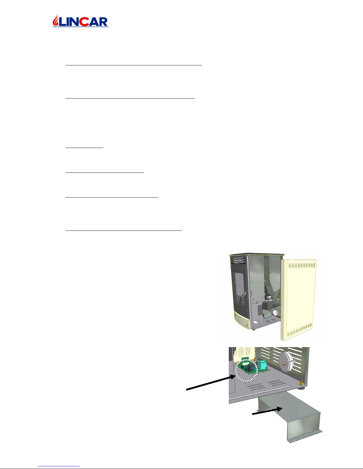
Protection Sheet
2.4 Safety
• Comfort for employing and safety functioning. The electronic digital control panel order
the combined action of combusted gas fan, combustible feed, convection fan and
environment temperature control. This control system guarantee the best conditions for
combustion and functioning, reducing to the minimum the exercise cost.
• The best efficiency with minimal emission. The wide surface of thermical exchange,
with the best air combustion control, has the best combustible exploitation as result.
The measured out pellet loading in the foyer allows a complete combustion with the
lower toxic values into the exhaust gas.
AUTOMATIC SAFETY FUNCTION
• Voltage Fall : After a short voltage fall, the stove stop than it will start again
automatically with normal function or with the light on phase. This operation is free of
risk for safety.
• Extinction for overheating : In case of stove overheating, the safety system turn off the
stove automatically. The stove should be lighted on again after a pause of 45 min for
cooling. If this situation will repeated please call the assistance service.
• Extinction for low temperature : If the stove temperature go down a certain value, the
stove turn off ( for example the combustible is finished ) This extinction could happen
also when the stove don’t complete the starting phase. The stove should be light on
again.
• Electrical safety device for over current : The stove is protected from overcurrent, with a
fuse ( see technical data ) placed on electronic card. Its substitution has to be done from
qualify staff, after having turn off the main switch and disconnect the stove from
electrical system :
• Unscrew the back and front screws that fix the
side and remove it.
• Attention to harness connection and electrical
connections.
• To enter to fuse, it’s necessary to remove the
protection sheet to electronic card, unscrewing
the fixing screws to stove bottom.
• Remove the damaged fuse and substitute it
with a new one.
• Reassemble the protection sheet for electronic
card, attention to not damage the harness .
• Replace the side and screw the back and front
fixing screws .
Fuse
Page 21
mod. 514 GB
21/28
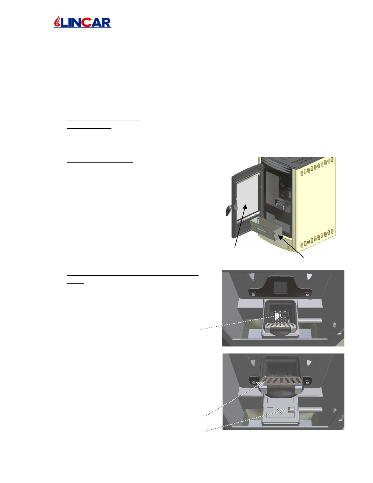
Burner basket
Spark tube
Protection pellet sheet
3 MAINTENANCE AND CLEANING
RESERVED TO USER
3.1 Ordinary Maintenance
• The frequency of the stove cleaning and maintenance is depending from pellet quality an
quantity. An high degree of humidity, ash, powder or chemicals adds inside the pellet
could increase the necessary cleaning and maintenance operations; so we recommend
again to employ a very high pellet quality
• Burner Tank Cleaning : To obtain the best performance during stove’s functioning,
EVERY DAY it’s necessary to clean the burner tank. Remove the tank and empty it
from every residuals, clean all the holes on the bottom and replace it into the stove being
careful to the position of starting glow plug.
• Ash Drawer cleaning
• The ash drawer is placed under the foyer, open
the fire door to enter it.
• Remove the ash drawer.
• The ash drawer has to be emptied every day from
combustion residuals employing the glove. This
operation has to be done with cold stove.
• Attention please to embers or hot pieces.
• Insert again the ash drawer into its place and
close the fire door.
• To forget to insert the ash drawer in its place it’s
dangerous.
• Ordinary Cleaning about combustion
room.. The combustion room has to be
checked to insure that air feed is regular.
The combustion room can be cleaned with a
vacuum cleaner. To scrape off the scale with
the appropriate piece of equipment .
• After having remove the burner basket to
scrape off the scale, replace it verifying that
the hole of big dimension has to be
correspondence with glow up tube.
• Check that the protection pellet sheet should
be placed on to the burners..
Ash Drawer
Fire Door
Page 22
mod. 514 GB
22/28
• Cleaning about pellet tank. Clean with a vacuum cleaner to remove every residual of
combustion. Before cleaning let finishing the pellet inside the apparatus and remove the
plug. If necessary take away also the tank grate
• External Cleaning.
This kind of operation has to be done when the stove is cold
− Iron / Steel parts : clean with a duster with appropriate detergent.
− Window / Ceramic parts : clean with a sponge with appropriate detergent and
dry with a duster.
− Painted parts : clean with a duster and neutral soap than dry with a duster.
We recommend to execute a regular maintenance of the appliance, of the fumes exhaust
ducts and of the chimney. In case of a long time of non utilization of the appliance,
before lighting the stove, verify that fume exhaust ducts and chimney are not obstructed.
3.2
Extraordinary maintenance (to be carried out by qualified staff only)
• At least once a year a general control on the appliance should be effected by a
specialized technician.
• It is advisable that every year a specialized after-sales service effects the following
maintenance operations:
− Exhaust gas ducts cleaning;
− Seat of exhaust gas motor cleaning;
− Verification and eventually replacement of gaskets;
− Chimney verification.
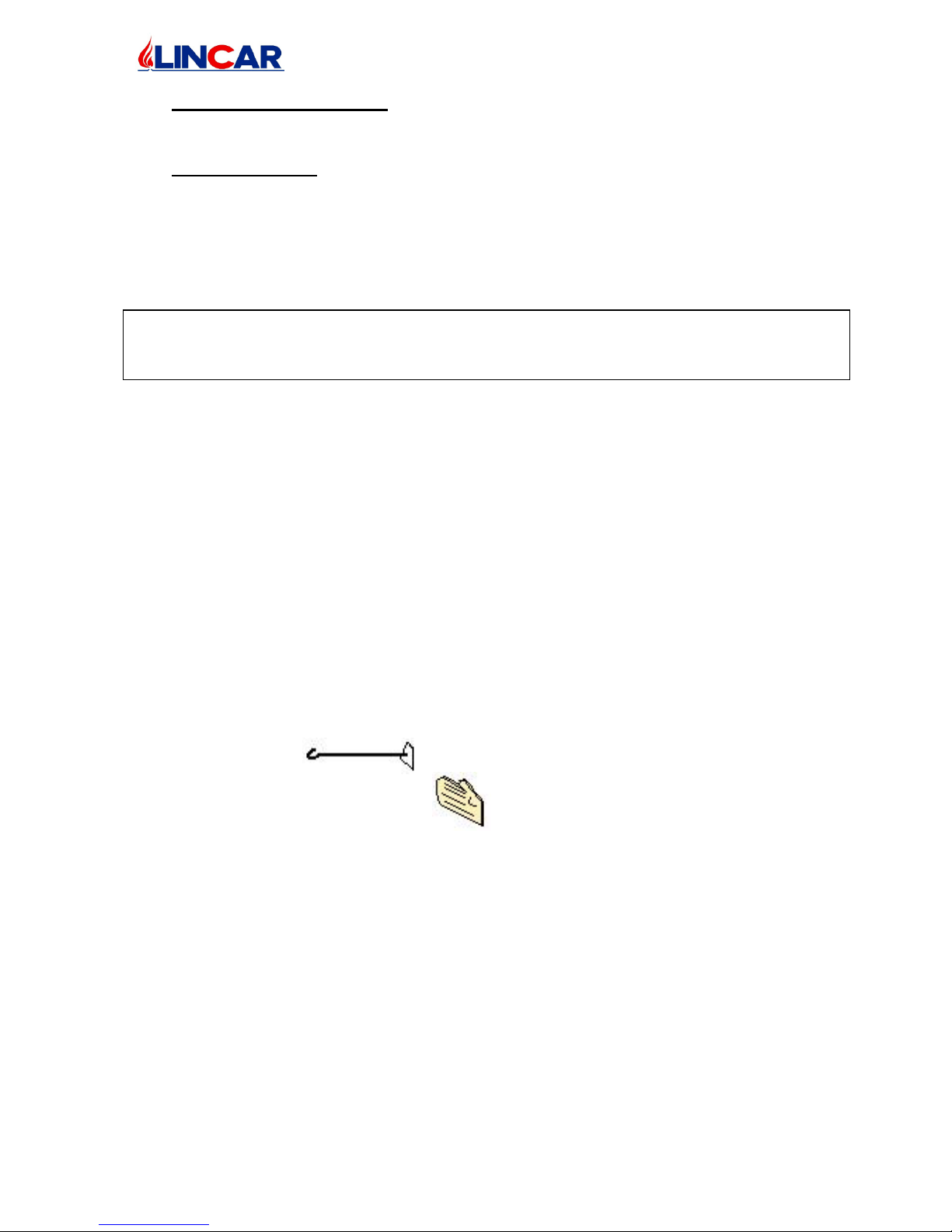
3.3 Accessories
The following accessories are supplied with the stove :
• To move residuals into the combustion chamber and burner tank during
functioning.
• For warm parts
Page 23

mod. 514 GB
23/28
3.4 Possible failure and its solution
DEFECT POSSIBLE CAUSE SOLUTION
The flame is weak and
orange colour, the pellet
accumulate inside tank
and door window is full
of ash.
Insufficient combustion
air.
Too much pellets fall
down in the basket burner
−
To clean the combustion basket
and to scrape off the scale to avoid
obstructions to change air. Employ
pellet of good quality..
− To check that the air combustion
circulation is not osbtructed by
ash.
− To check if the air tube or exhaus
fumetube are obstructed.
− To cheack the seal of fire door.
− To call the qualify staff.
− To check the combustion as
described preceding.
− To call the assistance centre to
make the regulations.
The flame turn off and
the stove automatically
blowing out.
−
Pellet tank in empty.
− Pellet are not
introduced.
− The thermostat take part.
− Bad quality Pellet.
− Low Pellet feed.
−
To load pellet tank.
− Read info about not introduction
pellet.
− Let the stove turned off. When the
stove is cold try to start it again.
− To check the regulation from Your
assistance centre. Repeat 1 cycle
of starting.
− To regulate the combustion
through the pellets correction (see
the chapter Combustion
Regulation)
− To require intervention specialist
staff.
Pellet are not introduced.
−
Pellet tank is empty.
− Screw Feeder or electric
card are defective.
− Screw feeder is
obstructed.
−
To check the tank and to load it.
− To check the apparatus from
assistance centre and to substitue
with original spare parts.
− To clean the tank and screw
feeder.
The stove blowing out
after few min.
Exhaus gas has not joint
the necessary temperature.
−
Try to start it again.
Control Pannel doesn‘t
turn on.
The stove doesn‘t receive
electricity.
−
To check the stove plug.
− To check the general switch will
be on 1 position.
− To check and substitue the fuse on
electric card.
Page 24
mod. 514 GB
24/28
Ash or soot out of the
stove.
−
The fire door is open
during combustion.
− No seal between the
combustion fan and
exhaus gas.
−
Please to close the fire door when
the stove is lighting.
− To seal every parts of exhaus
system and call the assistance
centre.
− Ignition harness could ne checked
only with apparatus not electrical
connected.
− Reparation has to be done by a
qualify staff.
ALARM SIGNAL ON CONTROL PANEL
Alarm Explication Possible reason Remedy
ALAr
Hot
PEL
Pellet tank
temperature
is too high
(over the
consent).
−
Obstruction of top and
frontal air intake.
− Temperature feeler breaking.
− Breaking convection motor.
−
To check the air intake.
− To substitute the feeler.
− To check convection motor
functioning.
ALAr
no
Acc
The
combustible
doesn’t
inflame
during the
ignition
phase – No
fire bearing.
−
No Pellets feed.
− Glow plug breaking
− No fire bearing from fumes
feeler.
− Pellets with ignition difficult.
−
To check Pellets tank level .
− To check the screw feeder
function.
− To check electrical connection.
− To substitute the glow plug.
− To check position, function and
electrical connection of
temperature fumes feeler.
− To employ combustible of
good quality.
ALAr
no
ASP
Chimney
exhaust
fumes
blocked.
−
Chimney blocked.
− Electrical connection break
off.
− Pressure switch breaking.
−
To check the chimney.
− To check electrical connection.
− To substitute switch breaking.
ALAr
Sic
FAiL
Temperature
pellets tank
or tangential
fan too
higher.
−
Up and Front Air intake
obstruction.
− Temperature thermostat
breaking.
− Convection Motor breaking.
−
To check air intake.
− To substitute thermostat.
− To check convection motor
ALAr
deP
FAiL
Chimney
exhaust
fumes
blocked
−
Chimney blocked.
− Electrical connection break
off
− Pressure switch breaking .
−
Check the chimney.
− Check electrical connection.
− Substitute switch breaking.
Page 25
mod. 514 GB
25/28
ALAr
Fan
FAiL
It’s not find
the rotation
of the
exhaust
fume motor.
−
Electrical connection break
off.
− Motor breaking.
−
Check feed motor connection
and encoder connection.
− Substitute motor.
ALAr
no
FirE
It’s not find
the fire on
foyer.
No Pellets feed.
−
Check Pellets tank level.
− Check screw feeder function.
− Possible screw feeder
obstruction.
ALAr
Hot
tEMP
The fumes
temperature
is too high
(over the
alarm
value).
−
Exit air convection is
blocked.
− Convection motor breaking.
− Wrong position fumes feeler.
−
Check air convection intake.
− Check convection motor
function.
− The fumes feeler is inserted too
deeply.
ALAr
Sond
Fumi
Noticed the
rupture of
the fume
feeler
−
Electrical connections
interrupted
− Rupture of the feeler
−
Verify the correct connection
of the feeler
− Change the fume feeler
CooL
FirE
Foyer
cooling.
−
Tension break off.
−
Wait for the automatic ignition.
ON
1...5
on t
The
temperature
in the room
is not found
−
The environment feeler is
broken
−
Check the environment feeler.
− Substitute the environment
feeler.
ALAr
no Acc
In case of glow plug breaking, waiting for repair, it’s possible to push the
ignition button for a manual ignition employing a small cube of firelighter.
Every intervention has be done from qualify staff !
Disconnect the equipment from electrical system before every maintenance operation
.
Every repairs must be done by our authorized assistance centre.
Lincar S.p.A is not responsible for damages to thing or people due to a wrong installation,
equipment tampering, improper use, bad maintenance or no observation of normative in
force. If considerate appropriate, Lincar spa reserves the right to make modifications without
notice and in every moment.
Some particulars and accessories illustrated in this handbook are not mass produced item so
its extra costs are to check at contract release.
Page 26

mod. 514 GB
26/28
Note:_______________________________________________________________________
___________________________________________________________________________
___________________________________________________________________________
___________________________________________________________________________
___________________________________________________________________________
___________________________________________________________________________
___________________________________________________________________________
___________________________________________________________________________
___________________________________________________________________________
___________________________________________________________________________
___________________________________________________________________________
___________________________________________________________________________
___________________________________________________________________________
___________________________________________________________________________
___________________________________________________________________________
___________________________________________________________________________
___________________________________________________________________________
___________________________________________________________________________
___________________________________________________________________________
___________________________________________________________________________
___________________________________________________________________________
___________________________________________________________________________
___________________________________________________________________________
___________________________________________________________________________
___________________________________________________________________________
Page 27

mod. 514 GB
27/28
Note:_______________________________________________________________________
___________________________________________________________________________
___________________________________________________________________________
___________________________________________________________________________
___________________________________________________________________________
___________________________________________________________________________
___________________________________________________________________________
___________________________________________________________________________
___________________________________________________________________________
___________________________________________________________________________
___________________________________________________________________________
___________________________________________________________________________
___________________________________________________________________________
___________________________________________________________________________
___________________________________________________________________________
___________________________________________________________________________
___________________________________________________________________________
___________________________________________________________________________
___________________________________________________________________________
___________________________________________________________________________
___________________________________________________________________________
___________________________________________________________________________
___________________________________________________________________________
___________________________________________________________________________
___________________________________________________________________________
Page 28

mod. 514 GB
28/28
4 Technical data plate.
You find here enclosed a copy of technical data plate.
Lincar S.p.A. Via E. Fermi, 5 – 42046 Reggiolo (RE) – Italy – Tel. +39 0522 972260 – Fax +39 0522 973625
 Loading...