

Page 1
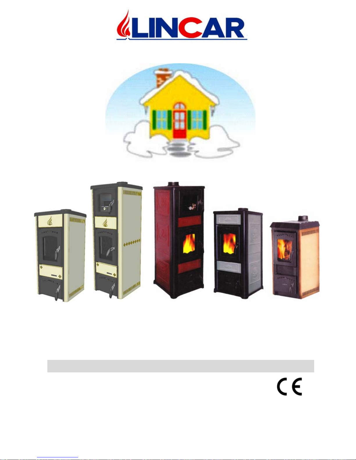
Re s ident ia l space he at i ng ap pl ianc e s f ir ed b y: W ood a nd L i g n it e
1/20
Alice
Mod. 480L
G
ioia
Mod. 470
Alice
Mod. 490L
Alice
Mod. 480N
Alice
Mod. 490N
USING INSTRUCTIONS AND MAINTENANCE
Equi pments built in conform ity with European Norms for marking :
Cod. 005.499 Rev. 6
Page 2
mo d. 4 70- 4 80 L- 49 0L- 4 80N-4 90N GB
2/20
Dear Customer,
We thank You for Your preferen ce; we t ry to built a product without default to
make Your li fe easi er, in any cas e we remember You to read this h andbook
before equipm ent usi ng . To leave out the reading of thi s h andbook h as to be
co ns ide r ed as “ NOT C ORRECT US E “ an d th e gu aran t ee can be in v ali d at ed.
.
INDEX
Chap. Description Pag.
1 Installation 3
1.1 Normative and prescriptions 3
1.2 Preliminary operations 3
1.3 A pp l iance positioning 3
1.4 Connection 4
1.5 Technical details 8
2 Using 9
2.1 Important warnings 9
2.2 Combustible 9
2.3 Starting 10
3 Maintenance and cleaning 14
3.1 Ordinary maintenance 14
3.2 Extrao rd inary maintenance 14
3.3 Accessories 14
3.4 Possible failure and its solution 17
4 Technical data plate 20
Page 3

mo d. 4 70- 4 80 L- 49 0L- 4 80N-4 90N GB
3/20
1 INS TALLATION
RESERVED TO INSTALLER
1.1 Normative and prescriptions
• Read carefully the contents of this handbook, it contains important information and
instructions for installation, use, maintenance and product safety.
• The appliance must be installed inside an environment considered suitable for installation
and use by competent authorities. All laws, standards and regulations in force on the
installation site must be observed, especially regarding fire prevention.
• Technological connection and appliance installation must be carried out by qualify staff
authorized to release a conformity certificate according with the normative in force and
current standards.
• All the normative concerning civil town planning and/or industrial in force must be
respected inside the environment of installation of the appliance. In every case the safety
devices should be always employ ed.
• The installation must be carried out and certified according to the normative in force
regarding installations, exhaust fumes connections, electricity, water, ventilation /
suction.
• The manufacturer disclaims all responsibility caused by no correct installation,
using, tamperin g, maintenance or no respect o f normativ e in force.
1.2 Preliminary operations
• Take away the packing.
• Before install ation, check the appliance integrit y . In case of doubt, do n ot us e the
appliance and call the dealer.
• Packing materials is for recycle, getting it in the specify container.
1.3 Appliance positioning
• The installation environment should have :
− A suitable floor for stove weight and calorific radiation, otherwise preventive
measures should be adopted. (Ex. P late for charge distribution ).
− A suitable floor for stove calorific radiation to guarantee the building against any
fire risk.
− The stove should be installed so that gas flue, chimney and cleaning could be easily
done.
− A minimal distance from flammable materials ( Security Distances)
− A suitable ventilation as normative in force.
FLOOR PROTECTION
• The equipment has to be put on a refractory surface. In case of flammable floor
( carpet, parquet ..) it’s necessary to put a refractory base( stainless steel, ceramic etc )
with the following dimensions :
− Hold up in front ≥ 500 mm;
− Hold up lateral ≥ 350 mm;
− Hold up back ≥ 100 mm.
Page 4
mo d. 4 70- 4 80 L- 49 0L- 4 80N-4 90N GB
4/20
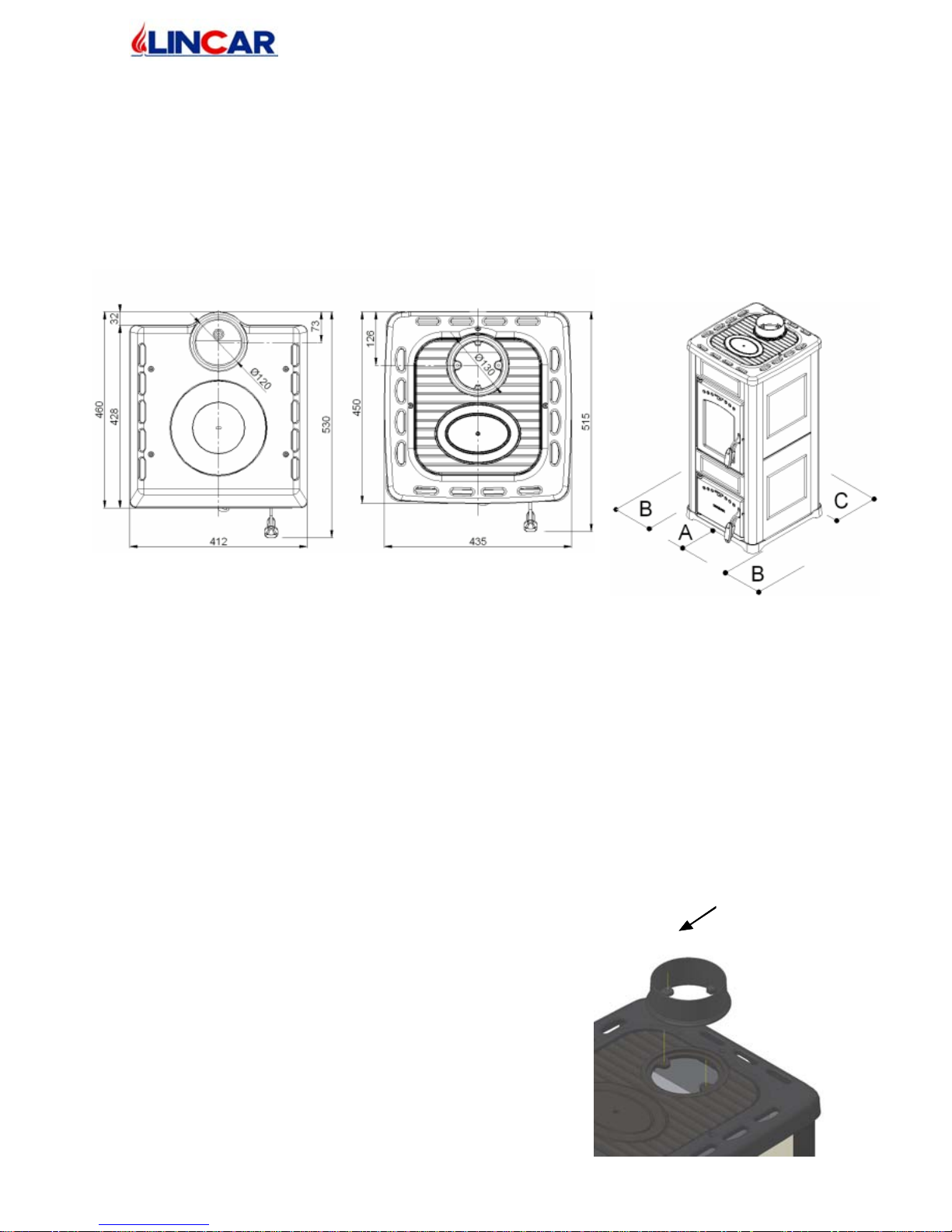
S ECURITY DISTAN CES
• From flammable object :
− A > 500 mm B > 200 mm C > 200 mm
• From flammable object and from principal wall in rein forced concrete :
− A > 1000 mm B > 350 mm C > 250 mm
• The minimal distance between the stove and every flammable object around it is 1.5
met er.
Mod 470 Mod 480L-490L-480N-490N
1.4 Connection
• Before connection check technical data reported in the technical plate ( Chap. 4 ) and
control t h at it co rrespond t o th e ones requ i red in t h e ord er.
• Al l h eat in g bi o mass equipment especial ly wo od s to v e h as to ev acuat e the comb us ti on
products in a flue built in conformity with normative in force.
• The following instructions describes „ informations for a good installation „ and it refers
to a normative in force but it are not to be consider exhaustive for installations laws.
CO LL AR EX HA UST FUMES ASSE MBLY
Only for mod. 480L-490L-480N-490N
• Take off the collar from the fire door.
• Place the collar on the top of the stove ( see the
picture ) assemble it with the screws.
Valid for all the Models
To measure fro m apparatus
external surface for every models
Collar Exhaust
Fumes
Page 5

mo d. 4 70- 4 80 L- 49 0L- 4 80N-4 90N GB
5/20
CHIMNE Y O R FL UE
• The chimney or flue should have the following characteristics:
− It’ s advisable read, follow and respect what indicated in the paragraphe 1.1
− Good sel of combustion products, impermeable and completely insulated as
normative condiction
− The flue has to be built with raw material suitable for normal mechanical stress,
warmth, action of combustion products and its condenses.
− The flow has to be vertical with deflections no hihgher that 45°.
− A right distance from co mbustible or flammable material, insulated with an air
cav it y o r ri ght in su l ator.
− Internal round section, the square or rectangular section should have round corner
with a ray not less than 20 mm.
− Internal section should be constant, free and indipendent.
− Rectangluar section with sides ration max of 1,5 .
− All manufacturer instruction should be respected concerning the section and the
building characteristic of the chimney or flue. For particular section, deviation of
section or path it will be necessary a complete inspection of exhaust fumes system.
− It‘ s advisable that the flue should be supplied by a „ chamber „ for solid material and
condenses collection, placed under the flue throat and easy to reach and to open. It
should be also supplied by a completely seal „little door“ for inspection.
− In case of fire of chimney or flue, employ the right system to soffocate the flames
an d c a ll fo r fi r e fi g h t e r .
E QUIPMENT CON NECTION TO FLUE AND E VACUATIO N OF COM BUST ION
PRODUCTS
• It’ s advisable to read, follow and respect what indicated in the paragraphe 1..1
• The flue should receive the exhaust fumes fro m an only heating equipment.
• It’s possible to realise an equipment composed from chimney and cooking oven with an
only exhaust fumes point head the chimney, for which the manufactures has to provide
the building characteristics of exhaust fumes channel.
• It’s prohibited to connect in the same flue, the heating equipment and the suction hood.
• It’ s prohibited to connect the exhaust pipe head closed space even if it is in open air.
• The direct exhaust fumes has to be done ahead roof and the exhaust pipe should have the
above characteristics.
CHIMNE Y CAP
• The chimney cap should have the following characteristics:
− It’ s advisable to read, follow and respect what indicated in the paragraphe 1.1
− Internal section equivalent with the chimney one.
− Exhaust section exit not lower to the double of the chimney internal one.
− Built in a way to avoid rain, snow or external body entrance, to ensure the right exit
of combustion products with any type of wind.
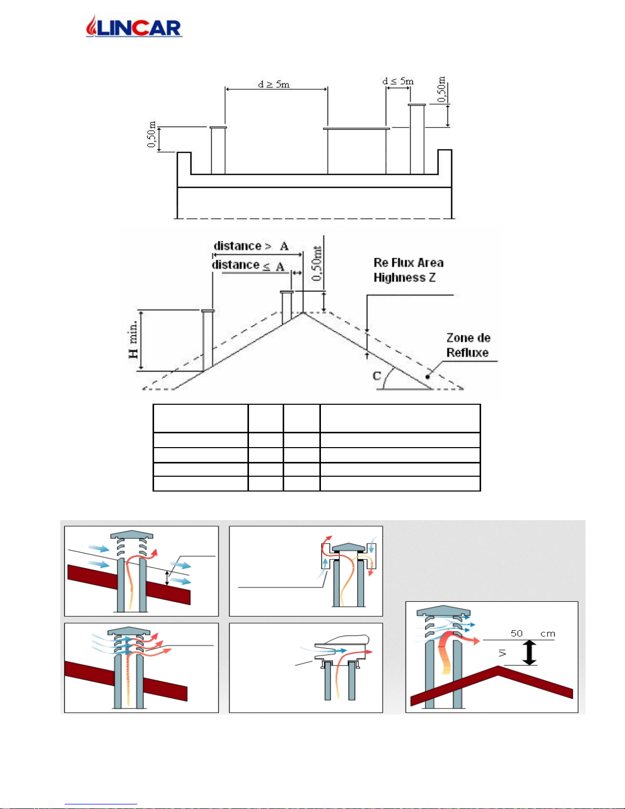
− Positioned to guarantee the right fumes dispersion especially or of re-flux area. This
area has several dimensions and conformations in function of inclination corner of
the covering so it’s necessary to apply the minimal highness as indicated in the
following tables:
Page 6
mo d. 4 70- 4 80 L- 49 0L- 4 80N-4 90N GB
6/20
Inclination Roof
C (°)
A H Re Flux Area Highness Z (m)
15 1,85 1,00 0,50
30 1,50 1,30 0,80
45 1,30 2,00 1,50
60 1,20 2,50 2,10
Re-flux
area
Chimney pot
wind damping
Chimney
Pot Wind
Damping
Revolving
chimney pot
for strong
horizontal
wind
Page 7
mo d. 4 70- 4 80 L- 49 0L- 4 80N-4 90N GB
7/20
CONNECTION TO FLUE
• The connect the heating equipment to the flue / chimney checking that the exhaust pipe
don’t take up the free section of flue.
• Employ only tubes supplied by seal gasket.
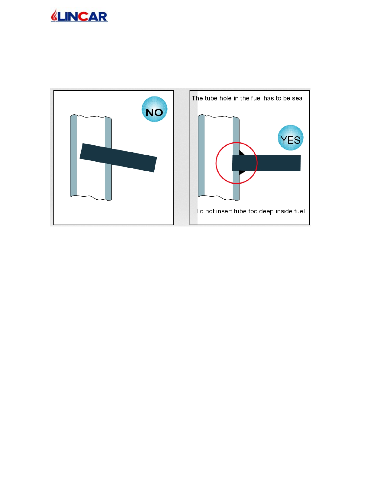
• To not use horizontal tubes ( max 1 meter ) and curves.
FEE D AIR CO MBUSTION DIRECT FRO M E NVIRONM ENT
• It’ s advisable to read, follow and respect what indicated in the paragraphe 1.1
• The eq ui p men t sh ou ld hav e t h e necessary air for comb us ti on, su pp li ed by ext ernal air
intake.
• The air intake should have the following characteristics :
a) Total free section min 200 cm²;
b) Connected directly with installation environment ;
c) P rotected with grate or lath ( attention to not reduce the min. section required on
point a) and placed so that to avoid obstruction.
• The air inflow can be also supplied from the adjacent room but the air intake should be
always free and connecter ahead outside. No chimney or suction hood should be present
in the environment of installation or into the nears ones.
• Inside the adjacent room the air intake should have the characteristics required in letter a
and c .
• The adjacent room can not be use as garage, warehouse of combustible material etc.
N OTE : Ext ractor fa ns when operati ng in the same room or space as the appliance may cau se
problems.
NOTE :The installation room shoul not be put in depressure by other appliances such as
s u ct ion h oo ds, ch im ne ys , e v a cu at io n flues , pre s en t in t he ro om i ts e lf o r i n th e a dj ac en t ro om s,
which are in comu nic ation.
Page 8
mo d. 4 70- 4 80 L- 49 0L- 4 80N-4 90N GB
8/20
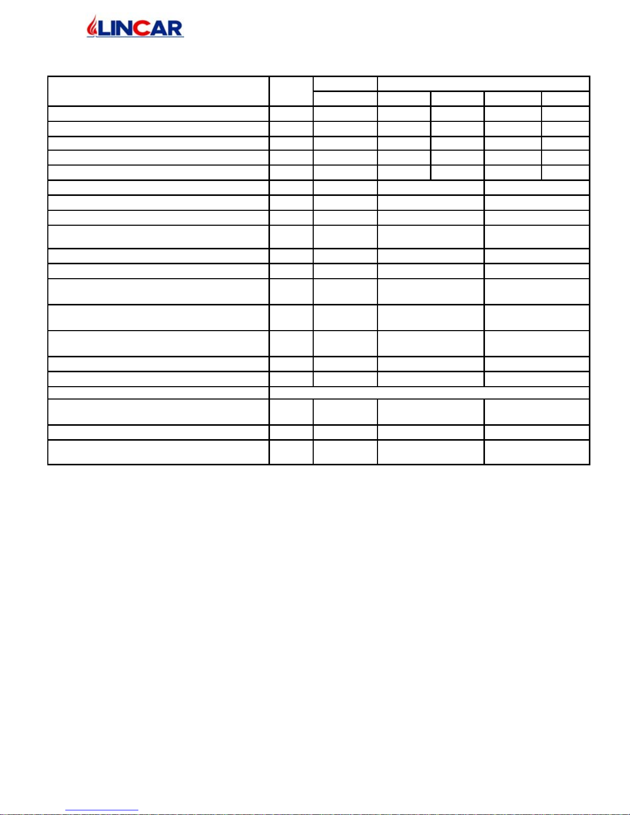
1.5 T E CH NI CAL S DET AIL S
GIOIA ALICE DESCRIPTION Mod.
470 480L 480N 490L 490N
WIDTH
mm 412 435 435 435 435
DEPHT
mm 460 450 450 450 450
HEIGHT
mm 880 925 900 1215 1190
EQUIPMENT WEIGHT Stell / Ceramic
kg 87 105 89 125 107
EQUIPMENT WEIGHT Stell / S.Stone kg -- 120 -- 142 --
Ø DIAMETER EXHAUST FUME
mm 120 130 130
TERMIC P OWER OU T P UT
kW 8.3 8.2 7.7
NOMINAL POWER OUTPUT
kW 6.0 6.0 6.0
EMISSION OF CO : Wood/Lignite
(AT 13% OXYGEN CONTENT)
% 0.29/0.20 0.10/0.11 0.40/0.16
ENERGY EFFICIENCY: Wood/Lignite
% 71 .8/ 72 .0 7 2 .8/ 70 .3 7 8 .1/ 74 .8
FLUE GAS TEMPE-RATURE: Wood/Lignite
°C 327 / 280 327 / 280 272 / 212
FUME CHIMNEY QUANTITY :
Wood/Lignite
g/sec 7.0 / 8.9 6.1 / 9.3 5.8 / 9.0
HEATING VOLUME INSULATION
FAVOURABLE
m3 150 150 150
HEATING VOLUME INSULATION
UNFAVOURABLE
m3 80 80 80
CHIMNEY DEPRESSION IN TEST
Pa 12 10 10
DEPRESSION CHIMNEY: MIN - MAX
Pa 10 ÷ 20 10 ÷ 20 10 ÷ 20
COMBUSTIBLE Wood logs of Beech size “1” and Lignite Bricks
COMBUSTIBLE LOADING MAX PRO H.
Wood/Lignite
kg 2.0 / 1.6 1.9 / 1.7
1.8 / 1.7
VOLUME OVEN
mm - - 215x315x220
HEATING VOLUME INSULATION
UNFAVOURABLE
Lt.
- - 15
Page 9
mo d. 4 70- 4 80 L- 49 0L- 4 80N-4 90N GB
9/20
2 USING - RESERVED TO USER
2.1 Important warnings
• To read carefully this section’s instruction which are very important for use, maintenance
and appliance safety.
• This handbook has to be ridden completely, in case of lack it can be consider an improper
use of the equipment so a not right use of it. To take care of this handbook to use it every
time it’s necessary.
• The appliance illustrated in this handbook must be employed only from qualify staff.
• The appliance should not be employ as incinerator.
• The appliance functioning, create high temperature on some internal and external
surfaces, with which user could get in touch so it’s necessary the maximu m attention!
• The appliance should be consider as active area of thermical exchange with warmth
surfaces so it’s necessary to be cautious to avoid the direct contact with children, animals
etc ….
• Employ the specific utensil to open the fire door.
• The right stove functioning is with closed doors and top rings completely assembled. If
the fire door window is broken and / or damaged or in case of bad functioning, the stove
can not be lighted till the problem has be solved.
• The operation of the machine must always happen under surveillance.
• The operation of the machine must always happen under surveillance.
• Every maintenance operation, every repairs or substitution, should be done from qualify
staff or assistance centre. Use only original spare parts.
• To not tamper the appliance. Do not obstruct air vents or heat dissipation openings.
• Every local , National or European normative in force has to be respected during the
installation.
• The safety distances from flammable material has to be observed and all the prescriptions
contained in chapter 1
2.2 Combustible
• The com bustible to employ is : WOOD or LIGNITE BRICKS
• Attention : It’s not allow the employ of liquid c ombustib le s or coal. Not use combustible as :
mais , pinuts,hazel , straw. Not use the pallet’s wood or refuse of the working of the wood as acacia,
conifer, fruit tree, it can damage the inside stove’s parts and its functioning.
BURNING WOOD
• The wood for its use is classified by
the : SIZE – MATERIAL –
HUMIDITY
• The wood that we recommend for
com bustible is : saisoned beech length
25÷30 cm with P.C.I. (calorific
power inside) 4,3 kWh/kg.
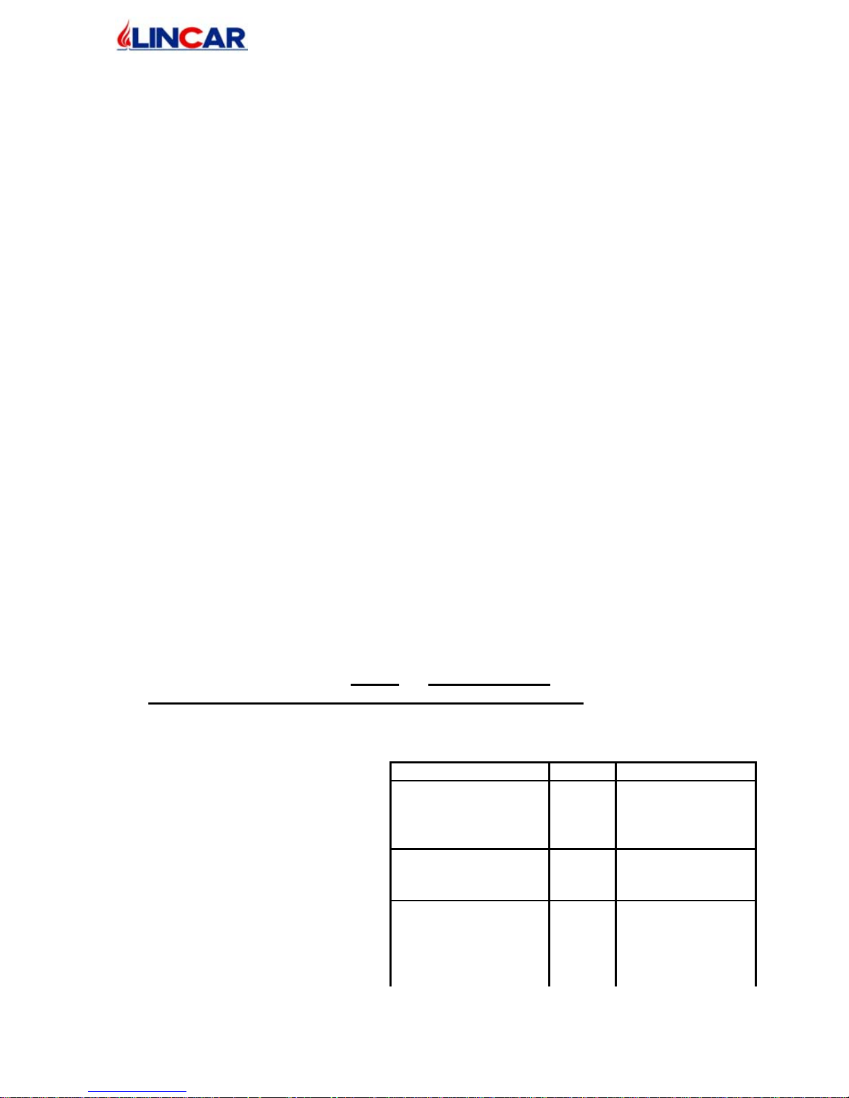
IDENTIFICATION NR. LETTERS
WOOD DIM :
Tondello
Trucioli
Sawdust
1
2
3
BIG
FLAKE
FINE
MATERIAL:
Fir - Larch
Oak - Beech
1
2
CONIFERS
LATIFOGLIE
HUMIDIT % :
> 35
14÷35
< 14
1
2
3
FRESCH
MID.SEASONED
SEASONED
Page 10
mo d. 4 70- 4 80 L- 49 0L- 4 80N-4 90N GB
10/20
• To guarantee a perfect combustion it’s
necessary to preserve the wood in a dry
and clean place.
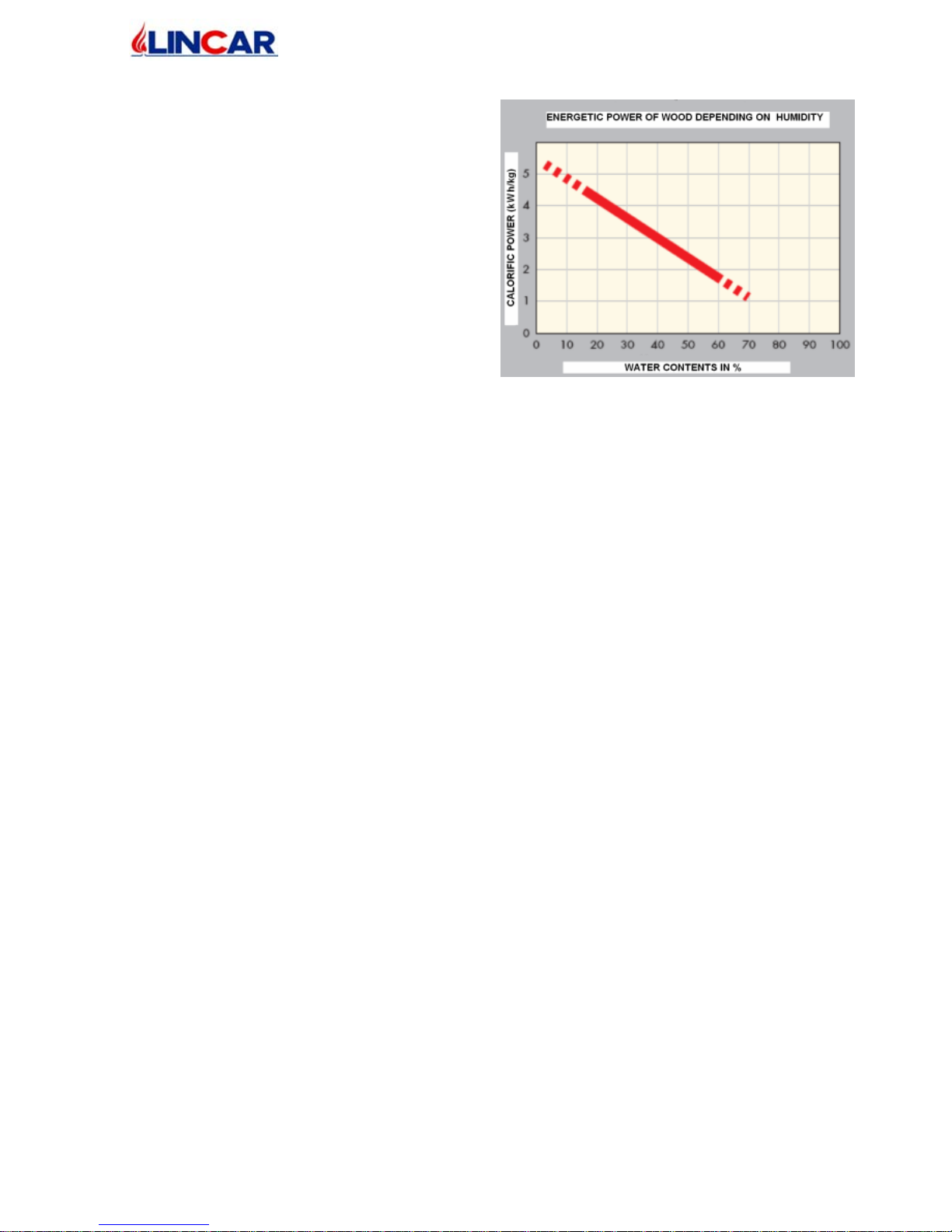
• The wood thermic output is related to its
humidity in %. (see the schedule ).
2.3 Starting
• The ap p li ance s ho ul d s et at work on ly after havi ng complet ed t h e following op erations:
complete assembling, connection to exhaust fumes duct and to the heating plant. A new
stove needs to complete the drying process of the paint. During the first heatings you can
notice the following situations:
- During the first ignitions the appliance may exhale bad smell. We suggest a good
aeration of the room till bad smells have been eliminated.
- The complete drying process will be obtained after some heating operations
WOOD LOADING
• The stove sh ou ld b e load ed man ually durin g th e functi on in g .
• The loading of combustible should be done when the flame is minimum to avoid
combustion products or fumes outlet from the fire door.
• To open the fire door, employ the fixture enclosed.
S TART ING AND FUNCT IONNIN G
N.B. For starting never use : alcool, fuel, or others liquid co mbustibles.
• In case of starting during particular cooling days or in a condition of low pressure, it’s
advisable to heat the flue before the starting, burning inside it some pieces of papers
• For the combustible quantities please read the “ Technical Data “ .
Page 11
mo d. 4 70- 4 80 L- 49 0L- 4 80N-4 90N GB
11/20
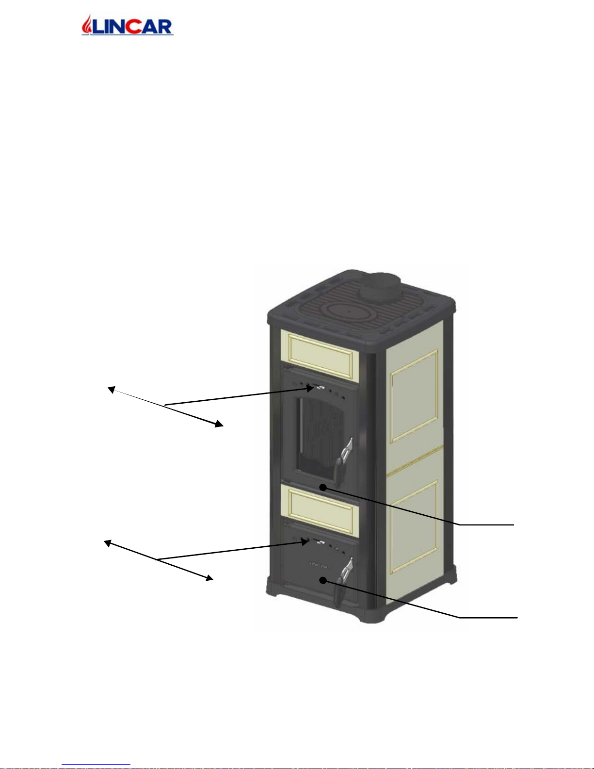
IGNITIO N
• To arrange on foyer a cube-lighting or a small quantity of paper, around 0,5 kg of wood
in small pieces. Open entirely the prime and secondary air, light the paper and close the
foyer door.
• When the stove is completely lighted, add some larger wood pieces. Repeat this operation
till when the stove has reached the “ Hourly Charge “ as indicated in the technical details,
than regulate the prime and secondary air as indicated in the chapter Regulations.
• It’s advisable to load the stove when the flame is not too high, to avoid the exit of
combustion products.
• During the stove’s functioning, it’s advisable to set several times the ash-grate to clean
often the brazier.
Fig. 1
Closed
Open
Prime Air
Closed
Open
Secondary Air
Ash
Door
F
ire
Door
Page 12
mo d. 4 70- 4 80 L- 49 0L- 4 80N-4 90N GB
12/20
L OADING - TO RE START WITH EMBE RS ( Moderates flames )
In case of starting with embers, go on as follows :
• Thicken the embers in the middle of the foyer .
• Open totally the prime air.
• Wait few minutes till in the brazier appears a flame sufficient for a new starting.
• Load some wood pieces and wait for the complete starting.
• Replace the prime air in the normal position as indicated in the chapter “ Regulations”.
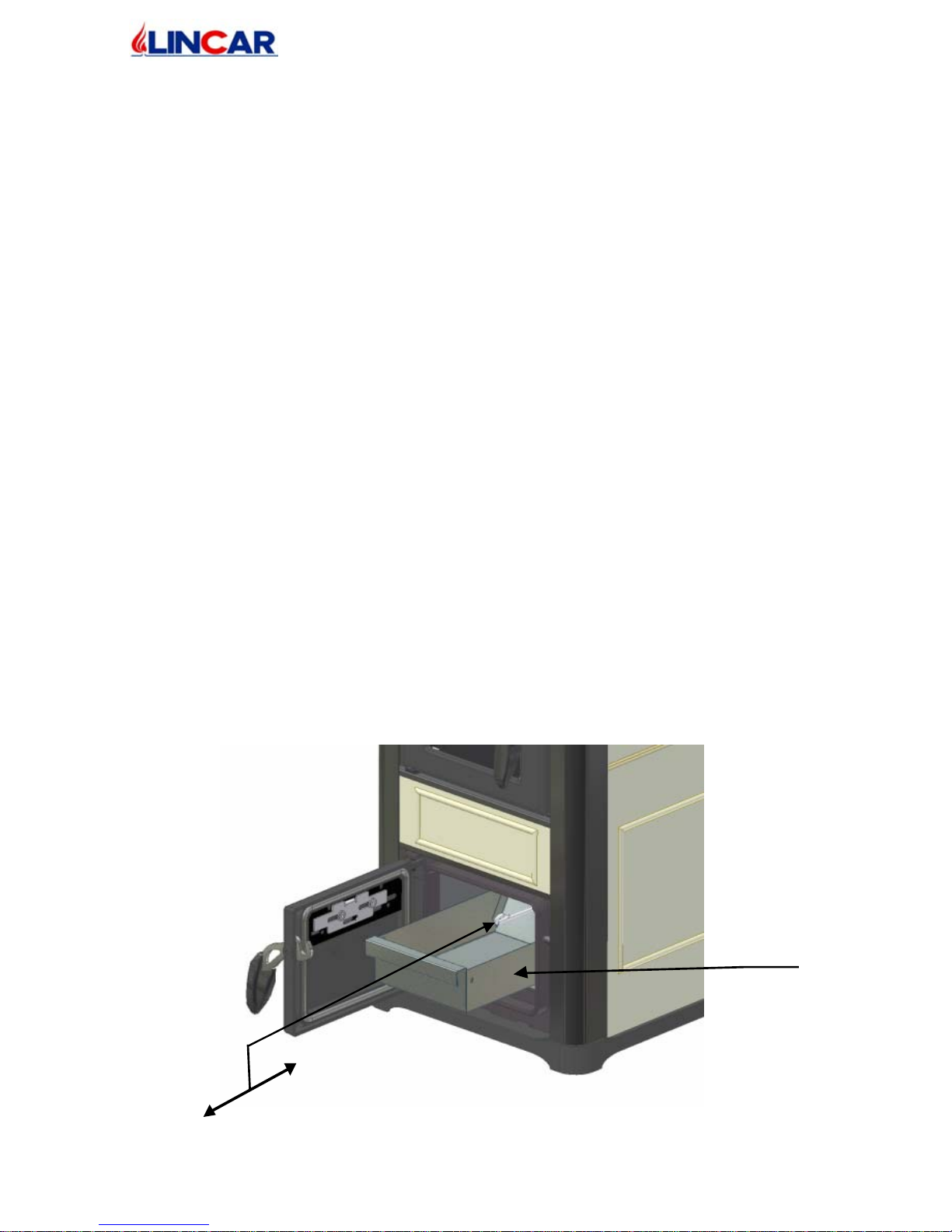
S HAK ING F OY ER GRAT E (Fig.1 – Fig.2)
• Open the ash door using the thermic glove and employing the poker, shake the grate of
the foyer. The ash will fall down into the ash drawer and the foyer will be always clean
and ready for next wood loading.
AS H DRAWER
• The ash drawer should be emptied from ash using the thermic glove. The ash drawer
emptying should be done when the stove is cold.
• The ash drawer is placed under the foyer, to reach it, it’s necessary to open the ash door.
• The emptying of ash drawer must be done when the stove is completely cold. Be careful
to the presence of ambers or warm pieces.
• Do not forget to insert the ash drawer in its place. The functioning of the stove without
the ash drawer has to be considered dangerous.
• Please employ the thermic glove in case of ash drawer’s emptying when the stove is still
warm.
Fig. 2
Ash shaker
Ash
Drawer
Page 13
mo d. 4 70- 4 80 L- 49 0L- 4 80N-4 90N GB
13/20
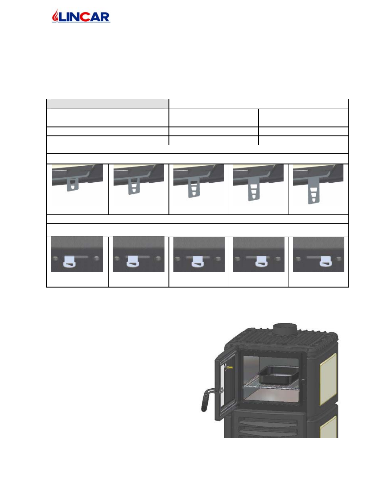
FIRE CO NTROL
• To obtain always a good compromise between the thermic performance and the
combustible consumption, it’s advisable to keep the following regulations : during the
normal employing the fire intensity can be regulated employing the prime and secondary
air lever.
• After the starting phase, the stove can be regulated as the following fire control position :
TYPE OF COMBUSTIBLE: WOOD LOGS
FIRE CO NTROL P OSIT ION
NO MINAL H EAT
OUTPUT
RE DUCED H EAT
OUTPUT
Position Prime Air Open 1/3 Closed
Position Secondary Air Middle Open Open 1/3
Fire Control Posi tions Prime Air
Closed
Open 1/3
Middle Open
Open 2/3
Open
Fi re C o ntro l P o s i ti o ns Secondary Air
Closed
Open 1/3
Middle Open
Open 2/3
Open
O VEN ( On ly Mod. 711-811 )
The oven’s employ is submitted to the usual
cooking norms as time, temperature and
quantity.
The oven is su pp li ed by a t h ermometer to
measure the internal temperature, an internal
grate and a small pot.
Page 14
mo d. 4 70- 4 80 L- 49 0L- 4 80N-4 90N GB
14/20
3 MAINTENANCE AND CLEANING
RESERVED TO USER
IMP ORTANT WA RNING
• Every maintenance and cleaning operations must be done when the stove is light off and
cold.
• The stove’ s co nd it io ns must be checked by ou r quali fy staff.
3.1 Ordinary maintenance
• The frequency of the stove cleaning and maintenance is depending from wood quality an
quantity. An high degree of humidity, ash, powder or chemicals adds inside the wood
could increase the necessary cleaning and maintenance operations; so we recommend
again to employ a very high quality of wood.
• Foyer Cleaning .
To obtain the best performance during stove’s functioning, EVERY
DAY it’ s necessary to clean the foyer grate, empty it from every residuals, clean all the
holes on the bottom and replace it into its place.
• External Cleaning
. This operation must be done when the stove is cold.
− Steel/cast iron parts : use a duster with specific detergent
− Windows/Ceramic: Use a sponge with specific detergent than dry the parts with a
dry duster.
− Painted parts : Use a duster and neutral soap than dry the parts with duster.
3.2 Ex traordinary maintenance (by qualify staff)
• EVERY YEAR IS RECOMMENDED THE FOLLOWING OPERATIONS
MAINTENANCE:
− Complete check up of the stove by qualify staff.
− Cleaning of exhaust gas.
− To check and eventually to replace of seal..
− To check the flue seal.
• We recommend to stipulate a contract with an after-sales service
3.3 Accessories
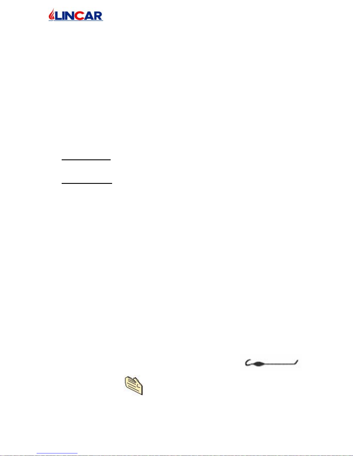
The following accessories are supplied with the stove :
• To move residuals into the combustion chamber and to move
ash-drawer.
• For warm parts
Page 15
mo d. 4 70- 4 80 L- 49 0L- 4 80N-4 90N GB
15/20
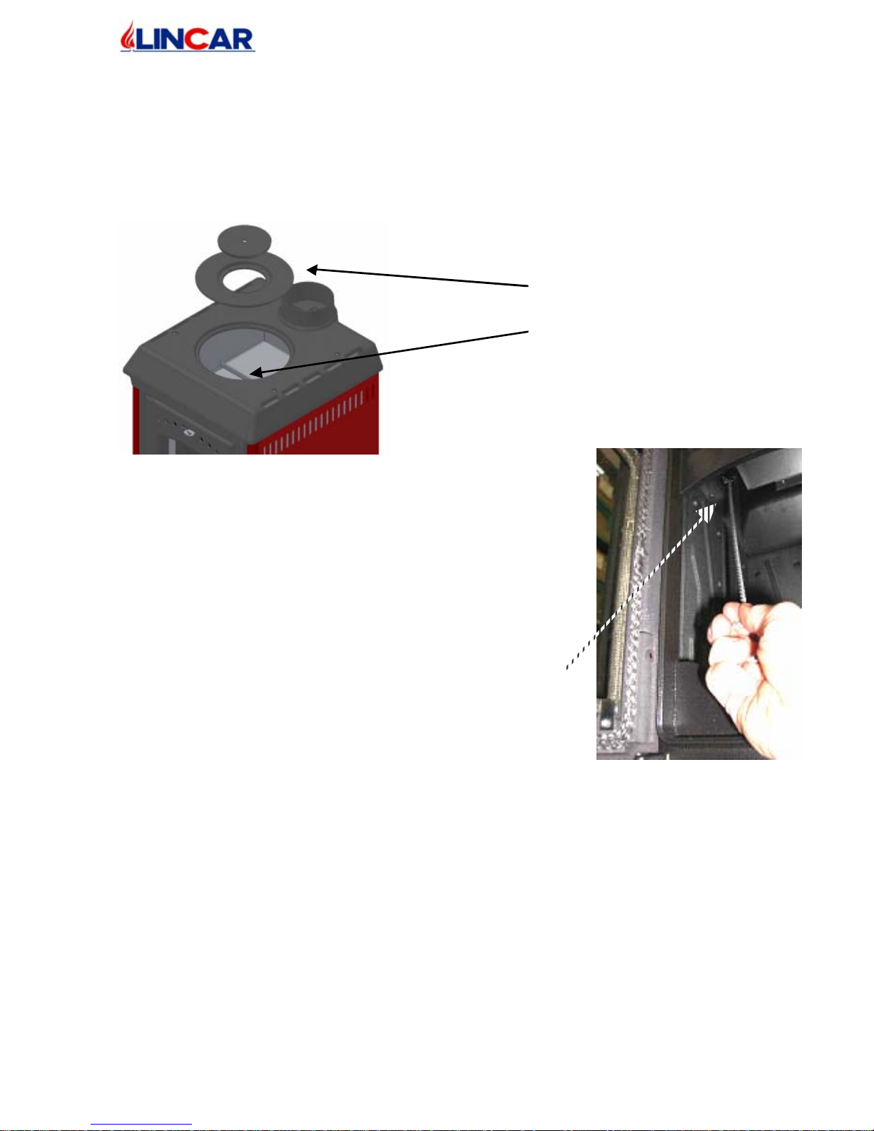
Cast iron rings
Fumes conveyor
INT E RNAL EXH AUS T GAS FUMES CLE ANING
• At least one per year or every time it’s necessary
• The inside cleaning must be done always when the stove is cold. All the necessary
equipment should be prepared before operations.
• Remove the two cast iron rings from the top, employing the hook poker, and clean
carefully the stove’s inside and fumes conveyor from residuals with a vacuum cleaner.
• When the cleaning operations are finished, reassemble the stove parts.
Cleani ng Internal Lateral Exha ust gas fume s
Mod. 490L – 490N :
• At least one per year or every time it’s necessary
• The inside cleaning must be done always when the stove is cold.
All the necessary equipment should be prepared before operations.
• The cleaning of lateral exhaust gas fumes should be done
removing the flame conveyor then employing the hook
poker clean the internal parts ( as in the picture)
• When the cleaning operations are finished, reassemble the
stove parts.
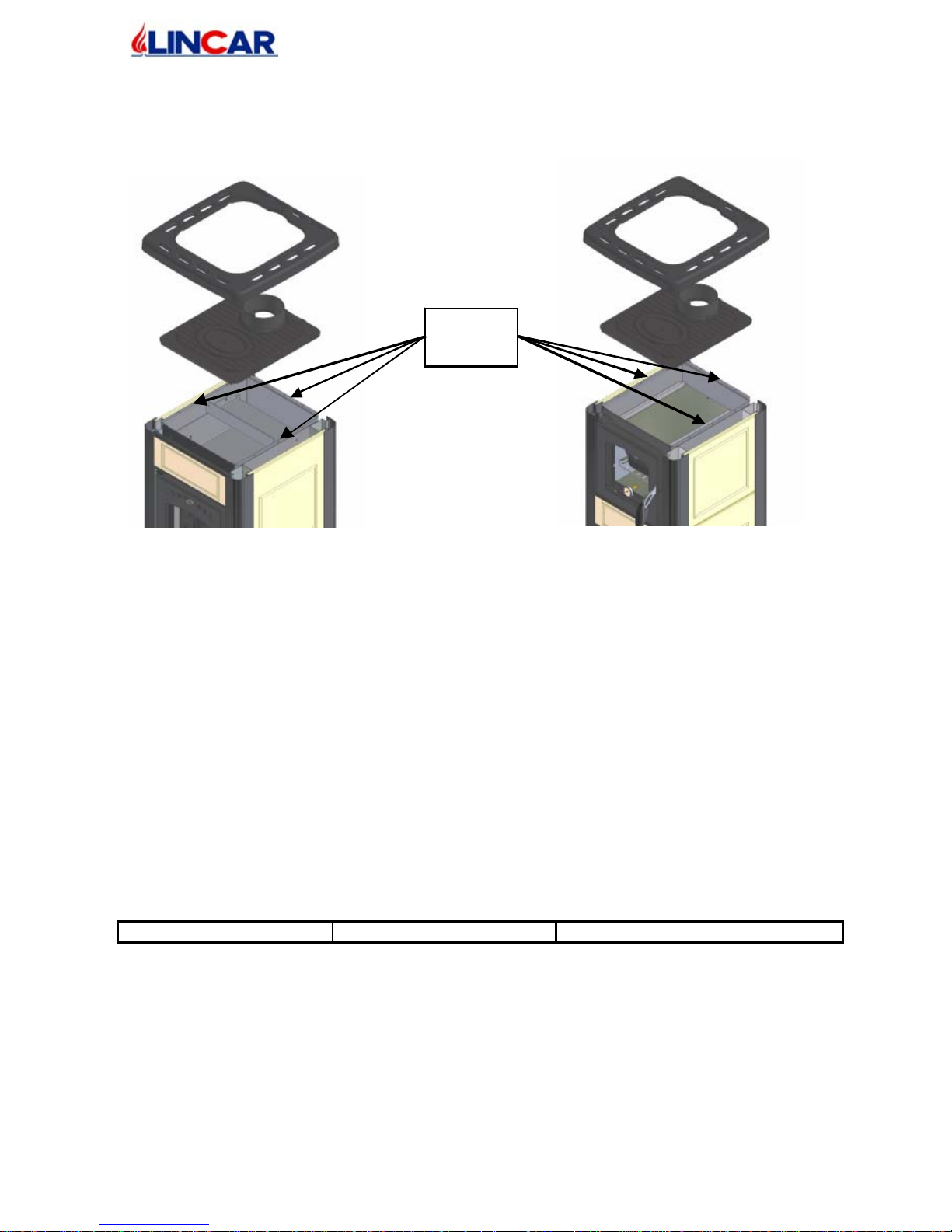
Internal exhaust gas fumes cleaning mod. 480L – 490L – 480N – 490N :
• At least one per year or every time it’s necessary
• The operation should be done by a qualify staff, because the top should be removed
mechanically.
• All the necessary equipment should be prepared before operations
a) Unscrew the frame from the cast iron top.
b) Unscrew the rest of fixing screws of cast iron top. Remove the top making attention to the
combustion residuals.
c) Clean the in si d e stov e parts removing every comb us ti on residuals .
d) Reassemble the stove to proceed to the assembly being repeated the operations in inverse
way.
Mod. 470
Page 16
mo d. 4 70- 4 80 L- 49 0L- 4 80N-4 90N GB
16/20
• N.B. To guarantee the correct stove functioning it’s necessary recover then perfect seal
between the sheet body and t h e cast iron to p removin g si li con residuals . Employ n ew
si li con ( s il i con resistant to hi gh t emp erat u res 30 0° ÷35 0° ) or employ a s eal in fibro
ceramic ( 10x3 ) in the position indicated in letter “ K”
3.4 Possible failure and its solution
DEFECT CAUSE SOLUTION
Mod. 480L – 480N
K
Mod. 490L – 490N
Page 17
mo d. 4 70- 4 80 L- 49 0L- 4 80N-4 90N GB
17/20
Windows fire door and/or
combustion chamber are
dirty of soot.
− Low draft <10 Pa.
− Wrong regulation.
− Too much combustible
in troduced.
− Combustible with high
humidity level.
− Not good quality
combustible.
− Check that the exhaust fumes
tube is not obstructed.
− Modify the flue : increase the
flue’s hight, end units not
correct, improve the isolation /
seal
− Read the charter “Regulations”.
− Reduce the quantities.
− Employ dried wood.
− Read the chapter “ Combustible”.
Not regular draft − Flue / exhaust fumes
unsuitable or dirty.
− Stove is dirty inside.
− Require chimney sweep
in terv ention.
− Clean the stove.
Too much dark fumes
from the exhaust
− Stove light on with
green wood.
− Stove dirty inside.
− Light on the stove with dried
wood.
− Call the assistance service.
Fumes escape from the
stove
− The fire/as h do o r is open
while the fire is burning.
− Draft insufficient.
− Not correct regulation
during ignition operation
− The s t ov e should be
cleaned.
− Close the doors.
− Call the chimney – sweeper to
check the chimney flue.
− Read the chapter “ Regulations”
and “Combustible to employ”.
− Clean all the connection tubes
and the chimney.
Eve ry int e rve nt ion has be don e from qu alif y st aff !
Lincar S.p.A is not responsible for damages to thing or people due to a wrong installation,
equipment tampering, improper use, bad maintenance or no observation of normative in
force. If considerate appropriate, Lincar spa reserves the right to make modifications without
notice and in every moment.
Some particulars and accessories illustrated in this handbook are not mass produced item so its
extra costs are to check at contract release.
Note:_______________________________________________________________________
___________________________________________________________________________
Page 18

mo d. 4 70- 4 80 L- 49 0L- 4 80N-4 90N GB
18/20
___________________________________________________________________________
___________________________________________________________________________
___________________________________________________________________________
___________________________________________________________________________
___________________________________________________________________________
___________________________________________________________________________
___________________________________________________________________________
___________________________________________________________________________
___________________________________________________________________________
___________________________________________________________________________
___________________________________________________________________________
___________________________________________________________________________
___________________________________________________________________________
___________________________________________________________________________
___________________________________________________________________________
___________________________________________________________________________
___________________________________________________________________________
___________________________________________________________________________
___________________________________________________________________________
___________________________________________________________________________
___________________________________________________________________________
___________________________________________________________________________
___________________________________________________________________________
___________________________________________________________________________
___________________________________________________________________________
Page 19

mo d. 4 70- 4 80 L- 49 0L- 4 80N-4 90N GB
19/20
___________________________________________________________________________
___________________________________________________________________________
___________________________________________________________________________
___________________________________________________________________________
___________________________________________________________________________
___________________________________________________________________________
___________________________________________________________________________
___________________________________________________________________________
___________________________________________________________________________
___________________________________________________________________________
___________________________________________________________________________
___________________________________________________________________________
___________________________________________________________________________
___________________________________________________________________________
___________________________________________________________________________
___________________________________________________________________________
___________________________________________________________________________
___________________________________________________________________________
___________________________________________________________________________
___________________________________________________________________________
___________________________________________________________________________
___________________________________________________________________________
___________________________________________________________________________
4 Technical data plate.
You find here enclosed a copy of technical dat a plate.
Page 20
mo d. 4 70- 4 80 L- 49 0L- 4 80N-4 90N GB
20/20
Lincar S.p.A. Via E. Fermi, 5 – 42046 Re ggiolo (RE) – Italy – Tel. +39 0522 972260 – Fax +39 0522 973625
 Loading...