

Page 1
Page 1 of 76
To learn more about LINAK, please visit:
www.linak.com
USER MANUAL
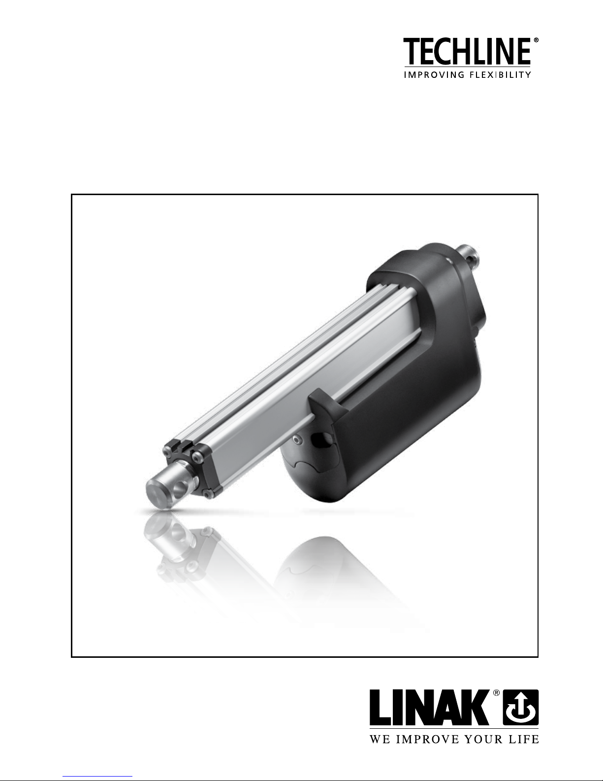
ACTUATOR LA36
Page 2

Page 2 of 76
Page 3

Page 3 of 76
Contents
Preface ................................................................................................................................................5
LINAK application policy .......................................................................................................................6
Chapter 1
Safety instructions ............................................................................................................................ 7-8
Chapter 2
Mounting guidelines ...................................................................................................................... 9-10
Mounting of cables ............................................................................................................................11
Electrical installation: ..........................................................................................................................12
Actuator without feedback .......................................................................................................12
Actuator with:
Endstop signal output ................................................................................................ 13-14
Relative positioning - Dual Hall ................................................................................... 15-16
Endstop signals and relative positioning - Dual Hall .................................................... 17-18
Relative positioning - Single Hall ................................................................................. 19-20
Endstop signals and relative positioning - Single Hall .................................................. 21-22
Absolute positioning - Analogue feedback ................................................................. 23-24
Endstop signals and absolute positioning - Analogue feedback .................................. 25-26
Absolute positioning - Mechanical potentiometer feedback ........................................ 27-28
Endstop signals and absolute positioning - Mechanical potentiometer feedback ......... 29-30
Absolute positioning - PWM....................................................................................... 31-32
Endstop signals and absolute positioning - PWM ........................................................ 33-34
Old CS36 (H-bridge) version - Dual Hall ...................................................................... 35-36
Old CS36 (H-bridge) version - Endstop signals ............................................................ 37-38
IC Basic ...................................................................................................................... 39-41
IC Advanced - with BusLink ........................................................................................ 42-44
Correct wiring of Power GND and Signal GND for IC Basic and IC Advanced .............................45
Actuator with Parallel .......................................................................................................... 46-48
The parallel system .............................................................................................................. 49-50
System monitoring for Parallel ...................................................................................................51
Alignment of the parallel actuator system .................................................................................51
Page 4

Page 4 of 76
Contents
Chapter 3
Troubleshooting ........................................................................................................................... 52-53
Troubleshooting for Parallel .......................................................................................................... 54-56
Chapter 4
Specifications .....................................................................................................................................57
Usage ................................................................................................................................................57
Actuator dimensions ..........................................................................................................................58
Built-in dimensions .............................................................................................................................59
Manual Hand Crank ...........................................................................................................................60
Speed and current curves: ............................................................................................................ 61-63
12V motor ...................................................................................................................................61
24V motor ...................................................................................................................................62
36V motor ...................................................................................................................................63
Label for LA36 ...................................................................................................................................64
Key to symbols ...................................................................................................................................64
LA36 Ordering example Econ .............................................................................................................65
LA36 Ordering example .....................................................................................................................66
Chapter 5
Maintenance ......................................................................................................................................67
Repair and spare parts .......................................................................................................................67
Main groups of disposal .....................................................................................................................67
Warranty ..........................................................................................................................................68
Declarations of conformity ........................................................................................................... 69-71
Declaration of incorporation of partly completed machinery ...............................................................72
Adresses ............................................................................................................................................76
Page 5

Page 5 of 76
Preface
Dear User,
We are delighted that you have chosen a product from LINAK®.
LINAK systems are high-tech products based on many years of experience in the manufacture and
development of actuators, electric control boxes, controls, and chargers.
This user manual does not address the end-user, but is intended as a source of information for
the manufacturer of the equipment or system only, and it will tell you how to install, use and
maintain your LINAK electronics. It is the responsibility of the manufacturer of the end-use product
to provide a User Manual where relevant safety information from this manual is passed on to the
end-user.
We are sure that your LINAK product/system will give you many years of problem-free operation.
Before our products leave the factory they undergo full function and quality testing. Should you
nevertheless experience problems with your LINAK product/system, you are always welcome to
contact your local dealer. LINAK subsidiaries and some distributors situated all over the world have
authorised service centres, which are always ready to help you.
LINAK provides a warranty on all its products. This warranty, however, is subject to correct use in
accordance with the specifications, maintenance being done correctly and any repairs being carried
out at a service centre, which is authorised to repair LINAK products.
Changes in installation and use of LINAK products/systems can affect their operation and durability.
The products are not to be opened by unauthorised personnel.
The User Manual has been written based on our present technical knowledge. We are constantly
working on updating the information and we therefore reserve the right to carry out technical
modifications.
LINAK A/S
Page 6

Page 6 of 76
LINAK application policy
The purpose of the application policy is to define areas of responsibilities in relation to applying a
LINAK product defined as hardware, software, technical advice, etc. related to an existing or a new
customer application.
LINAK products as defined above are applicable for a wide range of applications within Medical,
Furniture, Desk, and Industry areas. Yet, LINAK cannot know all the conditions under which LINAK
products will be installed, used, and operated, as each individual application is unique.
The suitability and functionality of the LINAK product and its performance under varying conditions
(application, vibration, load, humidity, temperature, frequency, etc.) can only be verified by testing,
and shall ultimately be the responsibility of the LINAK customer using any LINAK product.
LINAK shall be responsible solely that LINAK products comply with the specifications set out by
LINAK and it shall be the responsibility of the LINAK customer to ensure that the specific LINAK
product can be used for the application in question.
Page 7
Page 7 of 76
Chapter 1
Safety instructions
Please read this safety information carefully:
Be aware of the following three symbols throughout the user manual:
Warning!
Failing to follow these instructions can cause accidents resulting in serious personal injury.
Recommendations
Failing to follow these instructions can result in the actuator suffering damage or being
ruined.
Additional information
Usage tips or additional information that is important in connection with the use of the
actuator.
Furthermore, ensure that all staff who are to connect, mount, or use the actuator are in possession
of the necessary information and that they have access to this user manual.
Persons who do not have the necessary experience or knowledge of the product/products must not
use the product/products. Besides, persons with reduced physical or mental abilities must not use
the product/products, unless they are under surveillance or they have been thoroughly instructed in
the use of the apparatus by a person who is responsible for the safety of these persons.
Moreover, children must be under surveillance to ensure that they do not play with the product.
Before you start mounting/dismounting, ensure that the following points are observed:
• The actuator is not in operation.
• The actuator is free from loads that could be released during this work.
Before you put the actuator into operation, check the following:
• The actuator is correctly mounted as indicated in the relevant user instructions.
• The equipment can be freely moved over the actuator’s whole working area.
• The actuator is connected to a mains electricity supply/transformer with the correct voltage and
which is dimensioned and adapted to the actuator in question.
• Ensure that the voltage applied matches to the voltage specified on the actuator label.
• Ensure that the connection bolts can withstand the wear.
• Ensure that the connection bolts are secured safely.
Page 8
Page 8 of 76
During operation, please be aware of the following:
• Listen for unusual sounds and watch out for uneven running. Stop the actuator immediately
if anything unusual is observed.
• Do not sideload the actuator.
• Use only the actuator within the specified working limits.
• Do not step or kick on the actuator.
When the equipment is not in use:
• Switch off the mains supply in order to prevent unintentional operation.
• Check regularly for extraordinary wear.
Classification
The equipment is not suitable for use in the presence of a flammable anaesthetic mixture with
air or with oxygen or nitrous oxide.
Warnings:
• Do not sideload the actuator.
• Only use the actuator within specified working limits.
• When mounting the LA36 in the application ensure that the bolts can withstand the wear
and that they are secured safely.
• If irregularities are observed, the actuator must be replaced.
Recommendations:
• Do not place load on the actuator housing and do prevent impact or blows, or any other form
of stress to the housing.
• Ensure that the cable cover is mounted correctly. Use 1.5Nm torque.
• Ensure that the duty cycle and the usage temperatures for LA36 actuators are respected.
• Ensure that the cable cannot be squeezed, pulled or subjected to any other stress.
• Furthermore, it will be good practice to ensure that the actuator is fully retracted in the
“normal” position. The reason is that there will be a vacuum inside the actuator if it is
extended which over time can lead to water entering the actuator.
• If the actuator (without integrated controller) is mounted in an application where a mechanical stop prevents the endstop switches in the actuator from being activated, the actuator must
be equipped with an electrical safety device (current monitoring) or external limit switch.
Page 9

Page 9 of 76
Mounting guidelines
LINAK® linear actuators are quickly and easily mounted by slipping pins through the holes on each
end of the units and into brackets on the machine frame and the load.
The mounting pins must be parallel to each other as shown in Figure 1. Pins, which are not parallel
to each other, may cause the actuator to bend and be damaged.
The load should act along the stroke axis of the actuator since off centre loads may cause bending
and lead to premature failure. See Figure 2.
Make sure the mounting pins are supported in both ends. Failure to do so could shorten the life of
the actuator. Also, avoid applying a skew load on the actuator.
The actuator can rotate around the pivot point in the front and rear end. If this is the case it is of
high importance that the actuator is able to move freely over the full stroke length, both during
the development and during daily operation. Please pay special attention to the area around the
housing where parts can be trapped and cause damages to the application and actuator.
In applications with high dynamic forces LINAK recommends not to use the fully extended or
retracted position over longer time, as this can damage the endstop system permanently.
7 8 9
E
A
B
C
D
Right Wrong
Wrong Wrong
X
X
Figure 1
Figure 2
Chapter 2
Page 10
Page 10 of 76
Mounting guidelines
• The mounting pins must have the correct dimension
• The bolts and nuts must be made of a high quality steel grade (e.g. 10.8). No thread
on the bolt inside the back fixture or the piston rod eye
• Bolts and nuts must be protected so there is no risk for them to fall out
• Do not use a torque that is too high when mounting the bolts for the back fixture or
he piston rod eye. This will stress the fixtures
Please note:
The piston rod eye is only allowed to turn 0-90 degrees.
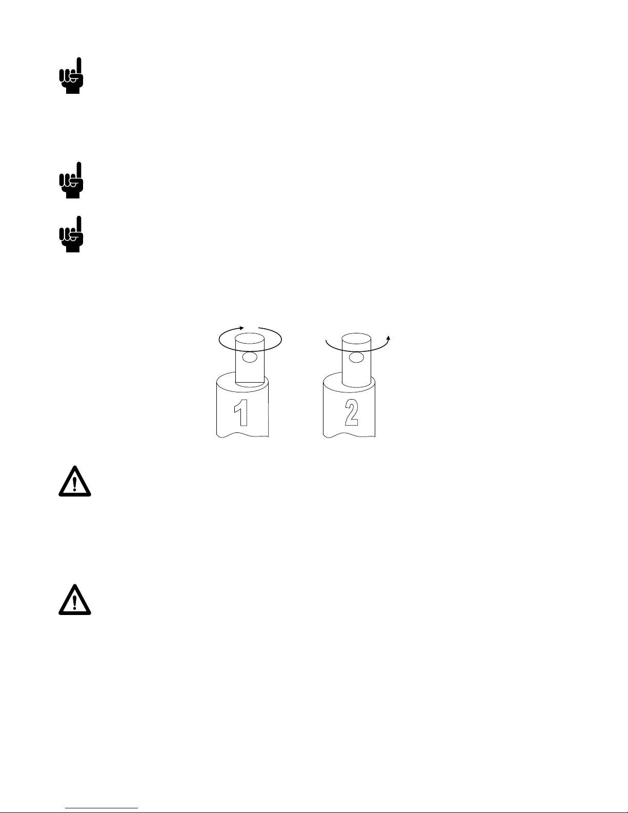
Instruction concerning the turning of the piston rod eye:
When mounting and taking into use, it is not permitted to make excessive turns of the
piston rod eye. In cases where the eye is not positioned correctly, it is permitted to first
screw the eye down to its bottom position, at a maximum torque of 2Nm (1), and thereafter a maximum half turn outwards again (2).
Warning!
If the actuator is used for pull in an application where personal injury can occur,
the following is valid:
It is the application manufacturer’s responsibility to incorporate a suitable safety
arrangement, which will prevent personal injury from occurring, if the actuator should
fail
Warning!
LINAK’s actuators are not designed for use within the following fields:
• Offshore installations
• Aeroplanes and other aircraft
• Nuclear power generation
SD/816030
Instruktion vedr. uddrejning af inderrør – LA27 + LA27C
Til salesbackup, brugsanvisning og datablad.
Ved montage og ibrugtagning, er det ikke tilladt at dreje unødvendigt mange gange på
stempelstangsrøret. Hvis øjet ikke er positioneret korrekt, er det tilladt først at skrue
røret i bund (1), og derefter skrue det maksimalt ½ omgang ud igen (2).
Page 11
Page 11 of 76
Mounting of cables
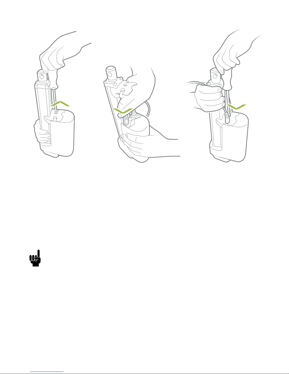
When changing the cables on a LINAK actuator, it is important that this is done carefully,
in order to protect the plugs and pins. Before the new cable is mounted, we recommend
that the socket is greased with vaseline, to keep the high IP protection and ensure an easy
mounting. Please be sure that the plug is in the right location and fully pressed in before
the cable lid is mounted.
Please note that if the cables are mounted and dismounted more than 3 times the plugs
can be damaged. Therefore, we recommend that such cables are discarded and replaced.
We recommend to take some precaution and design the wire connection in a way, where
the cable end is kept inside a closed, protected area to guarantee the high IP protection.
3. Slide the cover onto
the actuator.
The torque of the
cover screw is
approx. 1.5 ± 0.3 Nm
TORX 25IP
1. Unscrew the cover and
remove the two blind
plugs.
2. Plug in the power
cable and/or the
signal cable.
Page 12

Page 12 of 76
Electrical installation:
Actuator without feedback:
BROWN
BLUE
Connection diagram:
Fig. 1 : 36xxxxx00/10xxxxxx
36xxxxxxx000xx-xxxxxxxxxxxxxxx
Input/Output Specification Comments
Description Permanent magnetic DC motor.
See connection diagram,
fig. 1 above
Brown 12, 24 or 36VDC (+/-)
12V ± 20%
24V ± 10%
36V ± 10%
Under normal conditions:
12V, max. 26A depending on load
24V, max. 13A depending on load
36V, max. 10A depending on load
To extend actuator:
Connect Brown to positive
To retract actuator:
Connect Brown to negative
Blue To extend actuator:
Connect Blue to negative
To retract actuator:
Connect Blue to positive
Red Not to be connected
Black Not to be connected
Green Not to be connected
Yellow Not to be connected
Violet Not to be connected
White Not to be connected
I/O specifications:
Page 13
Page 13 of 76
Actuator with endstop signal output:
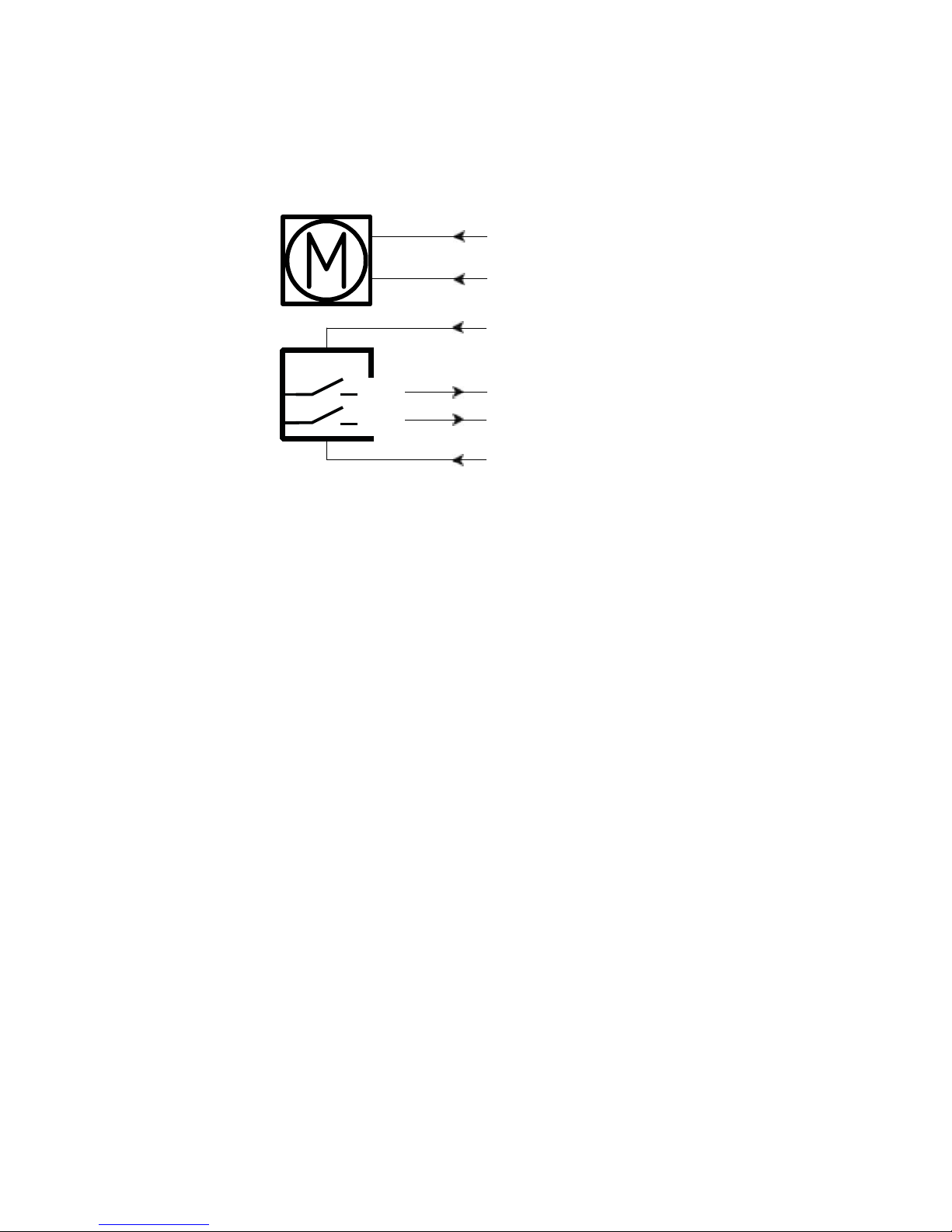
*YELLOW/GREEN:
Endstop signals out are NOT potential free!
If you wish to use the endstop signals, you will have to keep power on the brown, blue, red and
black wires, otherwise the signal will be lost.
Connection diagram:
Fig. 2 : 36xxxxx20xxxxxx
36xxxxxxx000xx-xxxxxxxxxxxxxxx
YELLOW*
GREEN*
IN
OUT
BROWN
BLUE
RED
BLACK
+
-
Page 14
Page 14 of 76
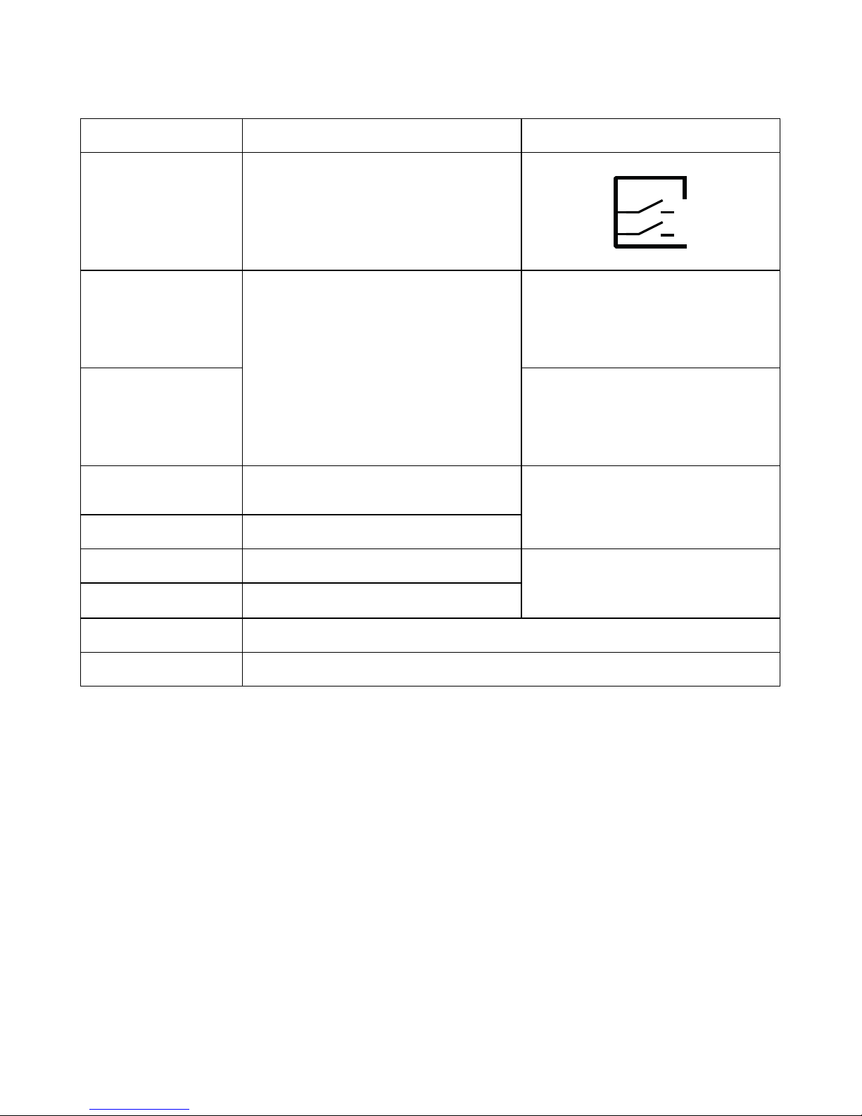
Actuator with endstop signal output:
I/O specifications:
Input/Output Specification Comments
Description The actuator can be equipped with
electronically controlled endstop
signals out.
See connection diagram,
fig. 2 on page 13
Brown 12, 24 or 36VDC (+/-)
12V ± 20%
24V ± 10%
36V ± 10%
Under normal conditions:
12V, max. 26A depending on load
24V, max. 13A depending on load
36V, max. 10A depending on load
To extend actuator:
Connect Brown to positive
To retract actuator:
Connect Brown to negative
Blue To extend actuator:
Connect Blue to negative
To retract actuator:
Connect Blue to positive
Red Signal power supply (+)
12-24VDC
Current consumption:
Max. 40mA, also when the
actuator is not running
Black Signal power supply GND (-)
Green Endstop signal out Output voltage min. V
IN
- 2V
Source current max. 100mA
NOT potential free
Yellow Endstop signal in
Violet Not to be connected
White Not to be connected
IN
OUT
Page 15
Page 15 of 76
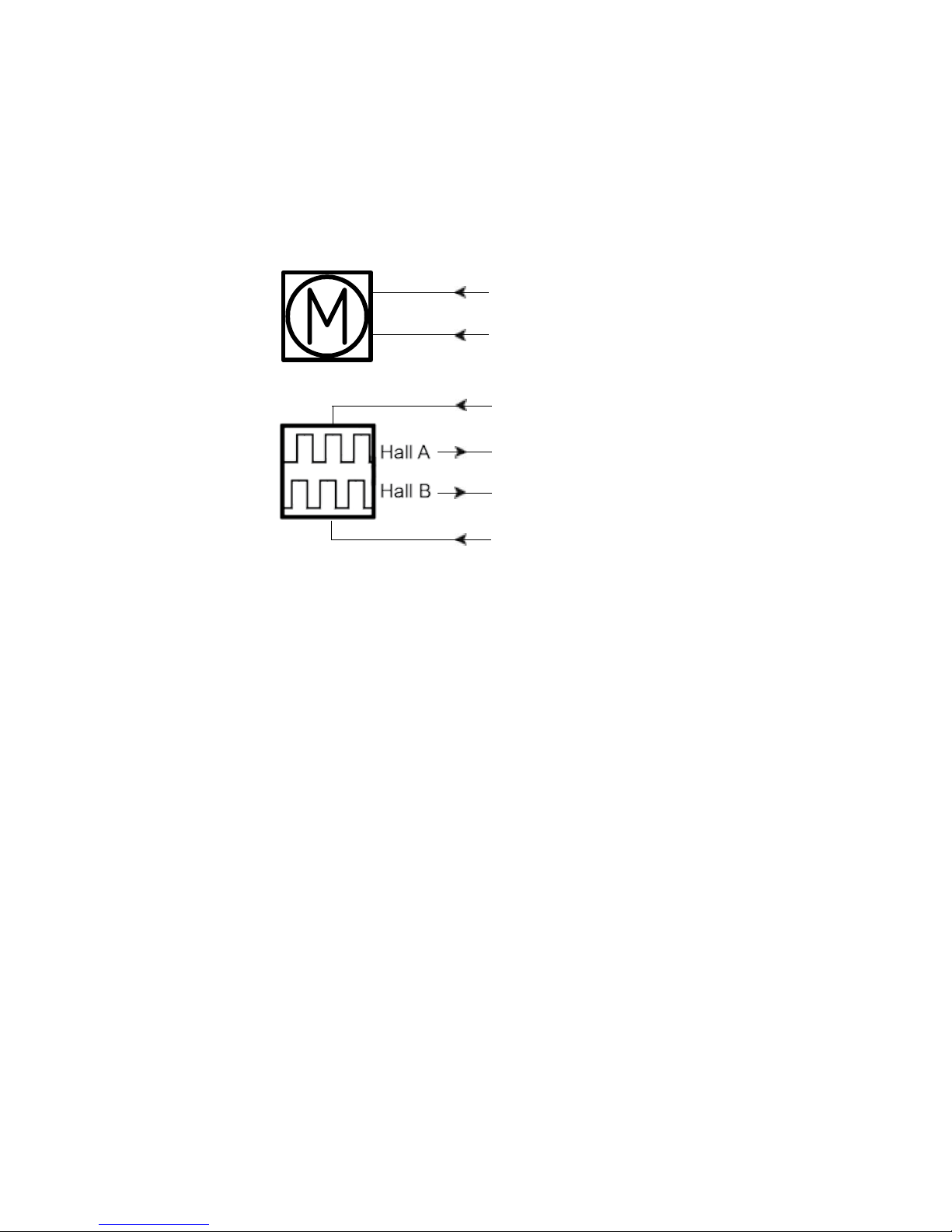
Actuator with relative positioning - Dual Hall:
Connection diagram:
Fig. 3 : 36xxxxx0H/1Hxxxxxx
36xxxxxxxH00xx-xxxxxxxxxxxxxxx
BROWN
BLUE
YELLOW
GREEN
RED
BLACK
+
-
Page 16
Page 16 of 76
Actuator with relative positioning - Dual Hall:
I/O specifications:
Input/Output Specification Comments
Description The actuator can be equipped
with Dual Hall that gives a relative
positioning feedback signal when
the actuator moves.
See connection diagram,
fig. 3, page 15
Brown 12, 24 or 36VDC (+/-)
12V ± 20%
24V ± 10%
36V ± 10%
Under normal conditions:
12V, max. 26A depending on load
24V, max. 13A depending on load
36V, max. 10A depending on load
To extend actuator:
Connect Brown to positive
To retract actuator:
Connect Brown to negative
Blue To extend actuator:
Connect Blue to negative
To retract actuator:
Connect Blue to positive
Red Signal power supply (+)
12-24VDC
Current consumption:
Max. 40mA, also when the
actuator is not running
Black Signal power supply GND (-)
Green Hall B
Movement per single hall
pulse:
LA362C Actuator = 0.4 mm
per pulse
LA363C Actuator = 0.7 mm
per pulse
LA363B Actuator = 1.0 mm
per pulse
LA363A Actuator = 1.7 mm
per pulse
LA365A Actuator = 2.9 mm
per pulse
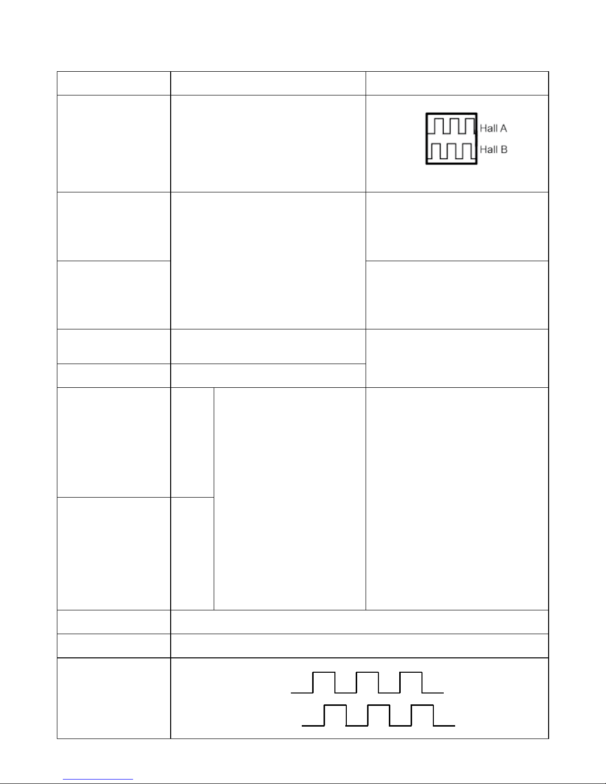
The Hall sensor signals are generated by the turning of the actuator gearing. These signals can be
fed into a PLC (Programmable
Logic Controller). In the PLC the
quadrature signals can be used to
register the direction and position
of the piston rod.
Output voltage min. V
IN
- 1V
Current output 12mA
Overvoltage on the motor can
result in shorter pulses.
N.B. For more precise measurements, please contact LINAK A/S.
Yellow Hall A
Violet Not to be connected
White Not to be connected
Diagram of Dual
Hall:
Fig. 3.1
Hall B
Hall A
Page 17
Page 17 of 76
Actuator with endstop signals and relative positioning - Dual Hall:
Connection diagram:
Fig. 4 : 36xxxxx2Hxxxxxx
36xxxxxxxH00xx-xxxxxxxxxxxxxxx
BROWN
BLUE
VIOLET*
WHITE*
IN
OUT
RED
YELLOW
BLACK
+
-
GREEN
*VIOLET/WHITE:
Endstop signals out are NOT potential free!
If you wish to use the endstop signals, you will have to keep power on the brown, blue, red and
black wires, otherwise the signal will be lost.
Page 18
Page 18 of 76
Actuator with endstop signals and relative positioning - Dual Hall:
I/O specifications:
Input/Output Specification Comments
Description The actuator can be equipped
with Dual Hall that gives a relative
positioning feedback signal when
the actuator moves.
See connection diagram,
fig. 4, page 17
Brown 12, 24 or 36VDC (+/-)
12V ± 20%
24V ± 10%
36V ± 10%
Under normal conditions:
12V, max. 26A depending on load
24V, max. 13A depending on load
36V, max. 10A depending on load
To extend actuator:
Connect Brown to positive
To retract actuator:
Connect Brown to negative
Blue To extend actuator:
Connect Blue to negative
To retract actuator:
Connect Blue to positive
Red Signal power supply (+)
12-24VDC
Current consumption:
Max. 40mA, also when the
actuator is not running
Black Signal power supply GND (-)
Green Hall B
Movement per single hall
pulse:
LA362C Actuator = 0.4
mm per pulse
LA363C Actuator = 0.7
mm per pulse
LA363B Actuator = 1.0 mm
per pulse
LA363A Actuator = 1.7
mm per pulse
LA365A Actuator = 2.9
mm per pulse
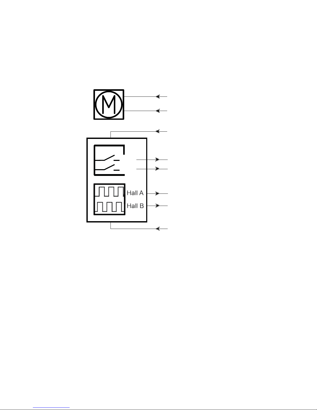
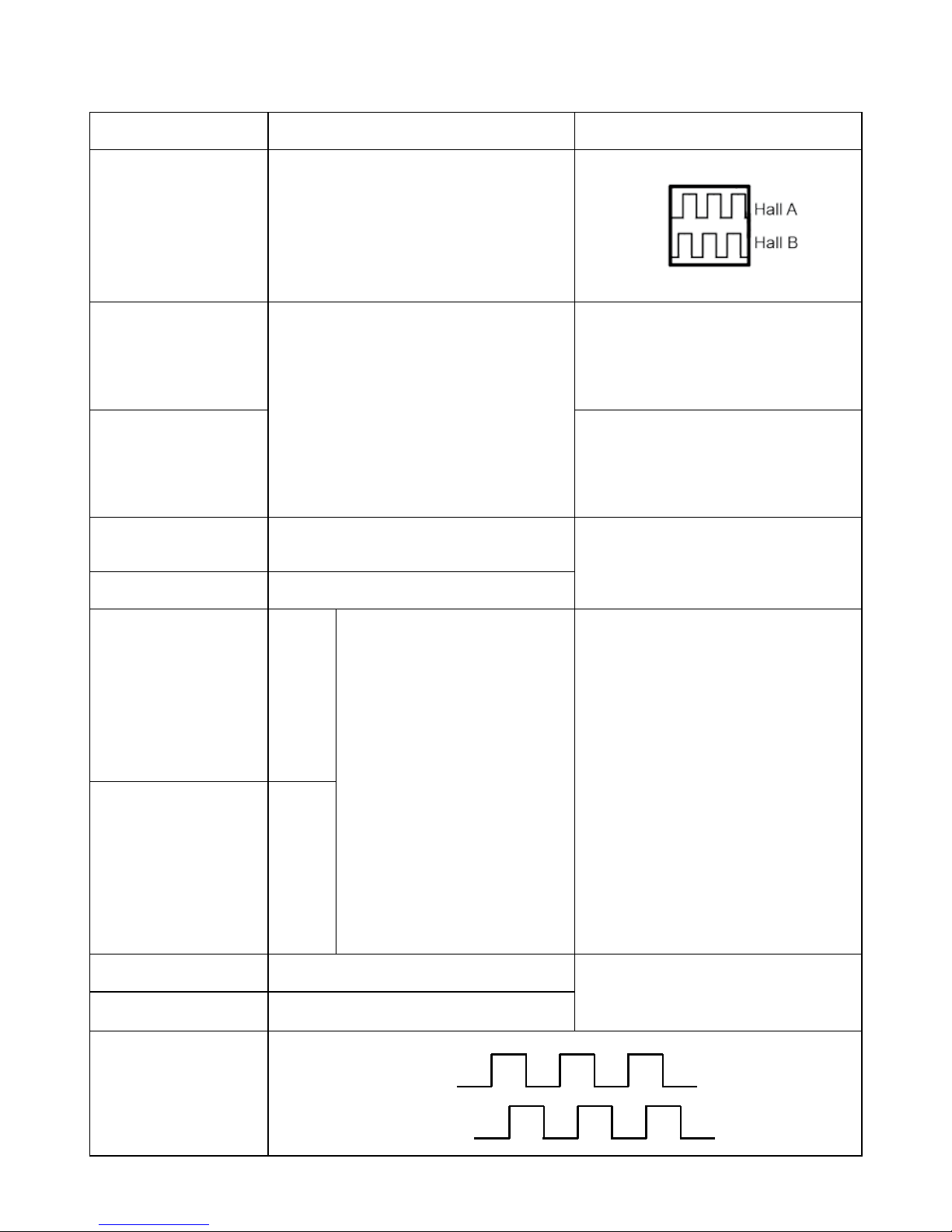
The Hall sensor signals are generated by the turning of the actuator gearing. These signals can be
fed into a PLC (Programmable
Logic Controller). In the PLC the
quadrature signals can be used to
register the direction and position
of the piston rod.
Output voltage min. V
IN
- 1V
Current output 12mA
Overvoltage on the motor can
result in shorter pulses.
N.B. For more precise measurements, please contact LINAK A/S.
Yellow Hall A
Violet Endstop signal in Output voltage min. V
IN
- 2V
Source current max. 30mA
NOT potential free
White Endstop signal out
Diagram of Dual
Hall:
Fig. 4.1
Hall B
Hall A
Page 19

Page 19 of 76
Actuator with relative positioning - Single Hall:
Connection diagram:
Fig. 5 : 36xxxxx0K/1Kxxxxxx
36xxxxxxxK00xx-xxxxxxxxxxxxxxx
BROWN
BLUE
RED
VIOLET
BLACK
+
-
Page 20

Page 20 of 76
Actuator with relative positioning - Single Hall:
I/O specifications:
Input/Output Specification Comments
Description The actuator can be equipped with
Single Hall that gives a relative
positioning feedback signal when
the actuator moves.
See connection diagram,
fig. 5, page 19
Brown 12, 24 or 36VDC (+/-)
12V ± 20%
24V ± 10%
36V ± 10%
Under normal conditions:
12V, max. 26A depending on load
24V, max. 13A depending on load
36V, max. 10A depending on load
To extend actuator:
Connect Brown to positive
To retract actuator:
Connect Brown to negative
Blue To extend actuator:
Connect Blue to negative
To retract actuator:
Connect Blue to positive
Red Signal power supply (+)
12-24VDC
Current consumption:
Max. 40mA, also when the
actuator is not running
Black Signal power supply GND (-)
Green Not to be connected
Yellow Not to be connected
Violet Single Hall output (PNP)
Movement per Single Hall pulse:
LA362C: Actuator = 0.1 mm per count
LA363C: Actuator = 0.2 mm per count
LA363B: Actuator = 0.3 mm per count
LA363A: Actuator = 0.4 mm per count
LA365A: Actuator = 0.7 mm per count
Frequency:
Frequency is 30-125 Hz on Single
Hall output depending on load and
spindle. Overvoltage on the motor
can result in shorter pulses.
Output voltage min. V
IN
- 2V
Max. current output: 12mA
Max. 680nF
N.B. For more precise
measurements, please contact
LINAK A/S.
Low frequency with a high load.
Higher frequency with no load.
Diagram of Single Hall:
White Not to be connected
Fig. 5.1
Micro Processor
Input Single Hall output
Hall B
Hall A
Page 21

Page 21 of 76
Actuator with endstop signals and relative positioning - Single Hall:
Connection diagram:
Fig. 6 : 36xxxxx2Kxxxxxx
36xxxxxxxK00xx-xxxxxxxxxxxxxxx
BROWN
BLUE
YELLOW*
GREEN*
IN
OUT
RED
VIOLET
BLACK
+
-
*YELLOW/GREEN:
Endstop signals out are NOT potential free!
If you wish to use the endstop signals, you will have to keep power on the brown, blue, red and
black wires, otherwise the signal will be lost.
Page 22

Page 22 of 76
Actuator with endstop signals and relative positioning - Single Hall:
I/O specifications:
Input/Output Specification Comments
Description The actuator can be equipped with
Single Hall that gives a relative
positioning feedback signal when
the actuator moves.
See connection diagram,
fig. 6, page 21
Brown 12, 24 or 36VDC (+/-)
12V ± 20%
24V ± 10%
36V ± 10%
Under normal conditions:
12V, max. 26A depending on load
24V, max. 13A depending on load
36V, max. 10A depending on load
To extend actuator:
Connect Brown to positive
To retract actuator:
Connect Brown to negative
Blue To extend actuator:
Connect Blue to negative
To retract actuator:
Connect Blue to positive
Red Signal power supply (+)
12-24VDC
Current consumption:
Max. 40mA, also when the
actuator is not running
Black Signal power supply GND (-)
Green Endstop signal out Output voltage min. V
IN
- 2V
Source current max. 100mA
NOT potential free
Yellow Endstop signal in
Violet Single Hall output (PNP)
Movement per Single Hall pulse:
LA362C: Actuator = 0.1 mm per count
LA363C: Actuator = 0.2 mm per count
LA363B: Actuator = 0.3 mm per count
LA363A: Actuator = 0.4 mm per count
LA365A: Actuator = 0.7 mm per count
Frequency:
Frequency is 30-125 Hz on Single
Hall output depending on load and
spindle. Overvoltage on the motor
can result in shorter pulses.
Output voltage min. V
IN
- 2V
Max. current output: 12mA
Max. 680nF
N.B. For more precise
measurements, please contact
LINAK A/S.
Low frequency with a high load.
Higher frequency with no load.
Diagram of Single Hall:
White Not to be connected
Fig. 6.1
Micro Processor
Input Single Hall output
Hall B
Hall A
Page 23

Page 23 of 76
Actuator with absolute positioning - Analogue feedback:
Connection diagram:
Fig. 7 : 36xxxxx1B/1Cxxxxxx
36xxxxxxxB00xx-xxxxxxxxxxxxxxx
36xxxxxxxC00xx-xxxxxxxxxxxxxxx
BROWN
BLUE
VIOLET
RED
+
BLACK
-
Page 24
Page 24 of 76
Actuator with absolute positioning - Analogue feedback:
I/O specifications:
Input/Output Specification Comments
Description The actuator can be equipped
with electronic circuit that gives an
analogue feedback signal when the
actuator moves.
See connection diagram,
fig. 7, page 23
Brown 12, 24 or 36VDC (+/-)
12V ± 20%
24V ± 10%
36V ± 10%
Under normal conditions:
12V, max. 26A depending on load
24V, max. 13A depending on load
36V, max. 10A depending on load
To extend actuator:
Connect Brown to positive
To retract actuator:
Connect Brown to negative
Blue To extend actuator:
Connect Blue to negative
To retract actuator:
Connect Blue to positive
Red Signal power supply (+)
12-24VDC
Current consumption:
Max. 60mA, also when the
actuator is not running
Black Signal power supply GND (-)
Green Not to be connected
Yellow Not to be connected
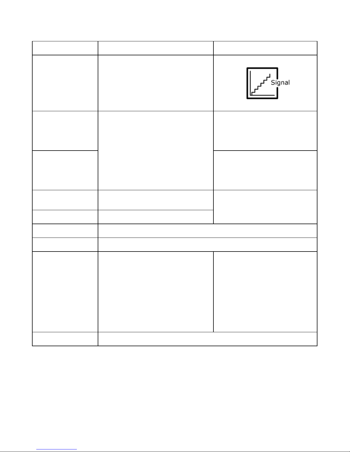
Violet Analogue feedback
0-10V (Option B)
0.5-4.5V (Option C)
Tolerances +/- 0.2V
Max. current output: 1mA
Ripple max. 200mV
Transaction delay 100ms
Linear feedback 0.5%
It is recommendable to have
the actuator to activate its limit
switches on a regular basis, to
ensure more precise positioning
White Not to be connected
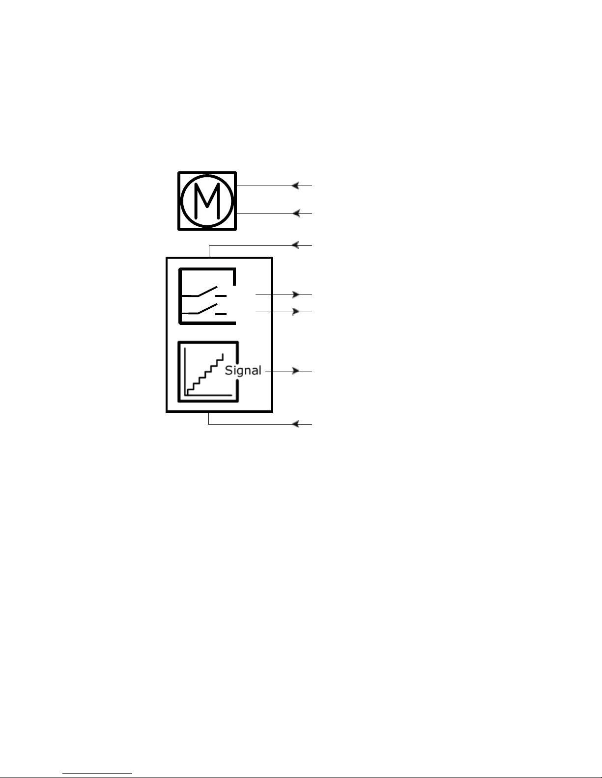
Page 25
Page 25 of 76
Actuator with endstop signals and absolute positioning Analogue feedback:
Connection diagram:
Fig. 8 : 36xxxxx2B/2Cxxxxxx
36xxxxxxxB00xx-xxxxxxxxxxxxxxx
36xxxxxxxC00xx-xxxxxxxxxxxxxxx
BROWN
BLUE
YELLOW*
GREEN*
IN
OUT
RED
VIOLET
BLACK
+
-
*YELLOW/GREEN:
Endstop signals out are NOT potential free!
If you wish to use the endstop signals, you will have to keep power on the brown, blue, red and
black wires, otherwise the signal will be lost.
Page 26

Page 26 of 76
Actuator with endstop signals and absolute positioning Analogue feedback:
I/O specifications:
Input/Output Specification Comments
Description The actuator can be equipped
with electronic circuit that gives an
analogue feedback signal when the
actuator moves.
See connection diagram,
fig. 8, page 25
Brown 12, 24 or 36VDC (+/-)
12V ± 20%
24V ± 10%
36V ± 10%
Under normal conditions:
12V, max. 26A depending on load
24V, max. 13A depending on load
36V, max. 10A depending on load
To extend actuator:
Connect Brown to positive
To retract actuator:
Connect Brown to negative
Blue To extend actuator:
Connect Blue to negative
To retract actuator:
Connect Blue to positive
Red Signal power supply (+)
12-24VDC
Current consumption:
Max. 60mA, also when the
actuator is not running
Black Signal power supply GND (-)
Green Endstop signal out Output voltage min. V
IN
- 2V
Source current max. 100mA
NOT potential free
Yellow Endstop signal in
Violet Analogue feedback
0-10V (Option B)
0.5-4.5V (Option C)
Tolerances +/- 0.2V
Max. current output: 1mA
Ripple max. 200mV
Transaction delay 20ms
Linear feedback 0.5%
It is recommendable to have
the actuator to activate its limit
switches on a regular basis, to
ensure more precise positioning
White Not to be connected
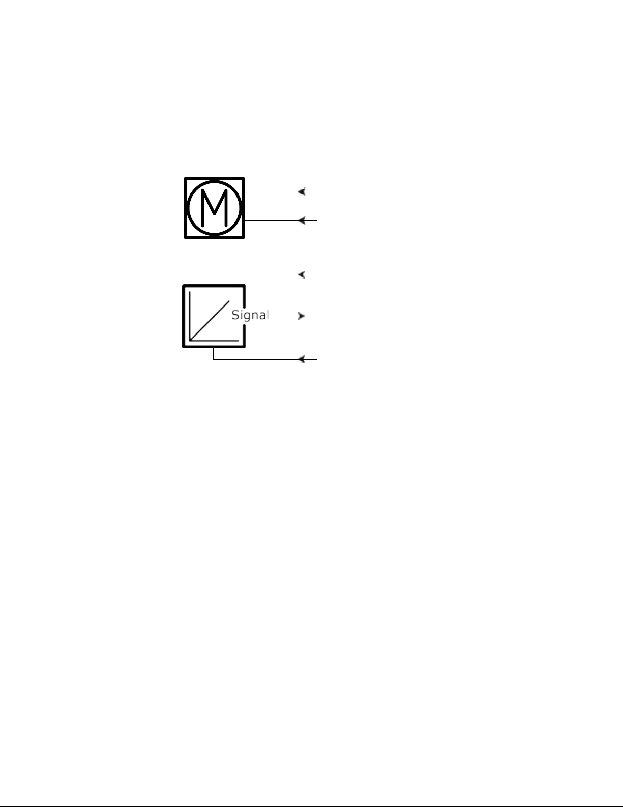
Page 27
Page 27 of 76
Actuator with absolute positioning - Mechanical potentiometer feedback:
Connection diagram:
Fig. 9 : 36xxxxx0P/1Pxxxxxx
36xxxxxxxP00xx-xxxxxxxxxxxxxxx
BROWN
BLUE
WHITE (VCC+ to POT)
VIOLET
BLACK
+
-
Page 28
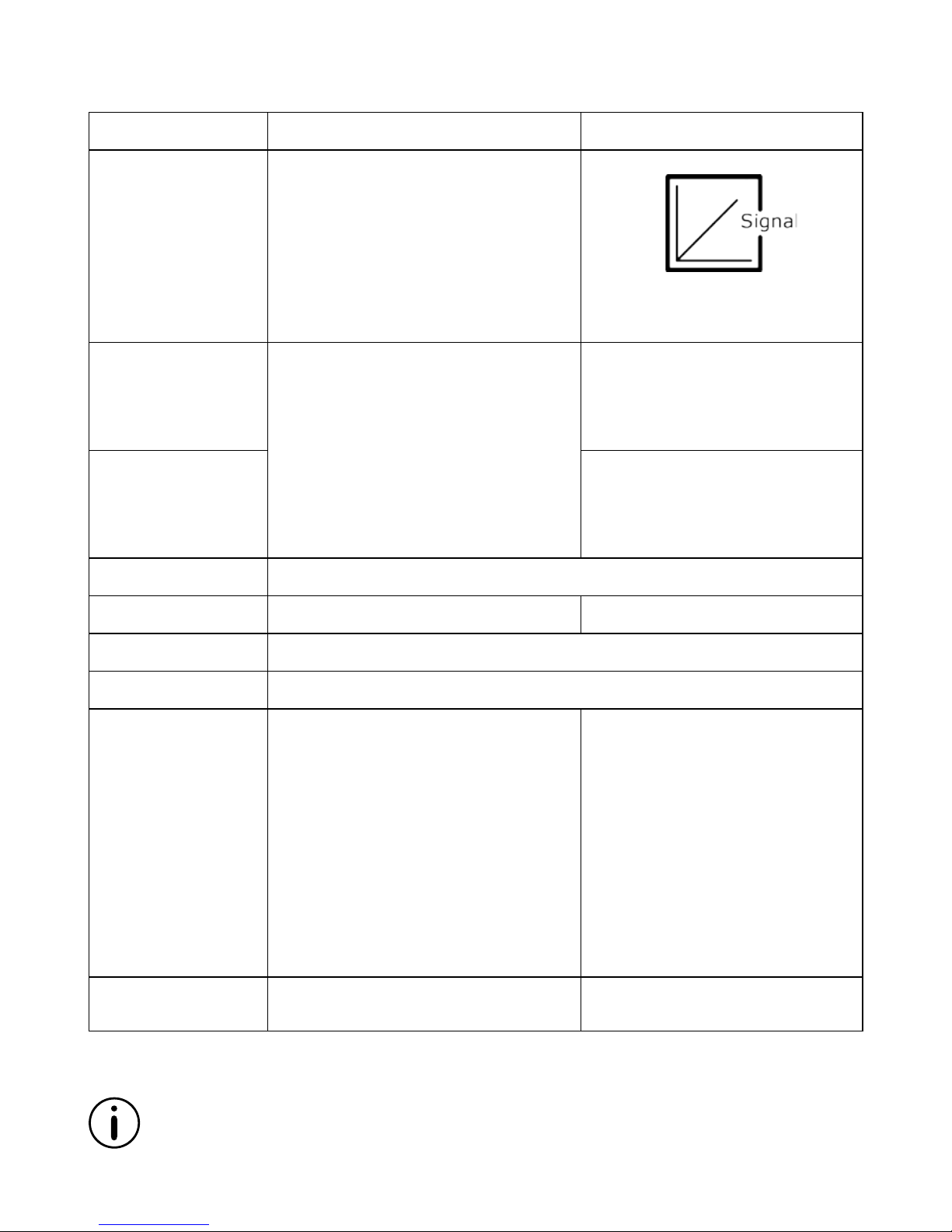
Page 28 of 76
Actuator with absolute positioning - Mechanical potentiometer feedback:
I/O specifications:
Input/Output Specification Comments
Description The actuator can be equipped with a
mechanical potentiometer, 10 kohm.
See connection diagram,
fig. 9, page 27
Bourns 0-10 kohm, 5%, 10-Turn
Type: 3540 Wirewound
Brown 12, 24 or 36VDC (+/-)
12V ± 20%
24V ± 10%
36V ± 10%
Under normal conditions:
12V, max. 26A depending on load
24V, max. 13A depending on load
36V, max. 10A depending on load
To extend actuator:
Connect Brown to positive
To retract actuator:
Connect Brown to negative
Blue To extend actuator:
Connect Blue to negative
To retract actuator:
Connect Blue to positive
Red Not to be connected
Black Signal power supply GND (-)
Green Not to be connected
Yellow Not to be connected
Violet Mechanical potentiometer output
Output range with 8mm spindle pitch:
0 kohm = 0mm stroke
10 kohm = 333mm stroke
Output range with 12mm spindle pitch:
0 kohm = 0mm stroke
10 kohm = 500mm stroke
Output range with 20mm spindle pitch:
0 kohm = 0mm stroke
10 kohm = 833mm stroke
+10V or other value
Output protection:
1 kohm protection resistor
Linearity: ± 0.25%
White VCC+ to POT
10VDC or other values
Please note that Potentiometer is not possible on variants with fast gear (Spindle pitch
20mm, H Gear).
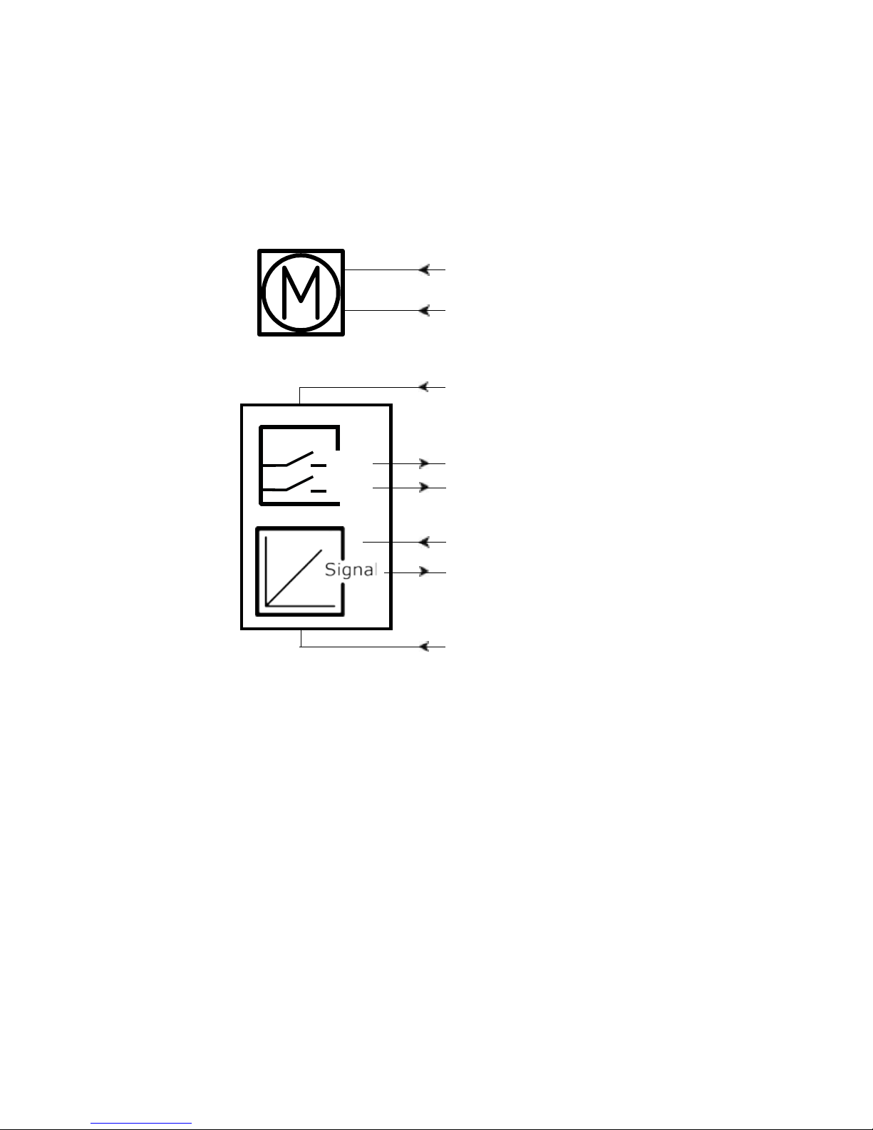
Page 29
Page 29 of 76
Actuator with endstop signals and absolute positioning Mechanical potentiometer feedback:
Connection diagram:
Fig. 10 : 36xxxxx2Pxxxxxx
36xxxxxxxP00xx-xxxxxxxxxxxxxxx
BROWN
BLUE
YELLOW*
GREEN*
IN
OUT
RED
VIOLET
BLACK
+
-
WHITE (VCC+ to POT)
*YELLOW/GREEN:
Endstop signals out are NOT potential free!
If you wish to use the endstop signals, you will have to keep power on the brown, blue, red and
black wires, otherwise the signal will be lost.
Page 30
Page 30 of 76
Actuator with endstop signals and absolute positioning Mechanical potentiometer feedback:
I/O specifications:
Input/Output Specification Comments
Description The actuator can be equipped with a
mechanical potentiometer, 10 kohm.
See connection diagram,
fig. 10, page 29
Bourns 0-10 kohm, 5%, 10-Turn
Type: 3540 Wirewound
Brown 12, 24 or 36VDC (+/-)
12V ± 20%
24V ± 10%
36V ± 10%
Under normal conditions:
12V, max. 26A depending on load
24V, max. 13A depending on load
36V, max. 10A depending on load
To extend actuator:
Connect Brown to positive
To retract actuator:
Connect Brown to negative
Blue To extend actuator:
Connect Blue to negative
To retract actuator:
Connect Blue to positive
Red Signal power supply (+)
12-24VDC
For endstop signals
Black Signal power supply GND (-)
Green Endstop signal out Output voltage min. V
IN
- 2V
Source current max. 100mA
NOT potential free
Yellow Endstop signal in
Violet Mechanical potentiometer output
Output range with 8mm spindle pitch:
0 kohm = 0mm stroke
10 kohm = 333mm stroke
Output range with 12mm spindle pitch:
0 kohm = 0mm stroke
10 kohm = 500mm stroke
Output range with 20mm spindle pitch:
0 kohm = 0mm stroke
10 kohm = 833mm stroke
+10V or other value
Output protection:
1 kohm protection resistor
Linearity: ± 0.25%
White VCC+ to POT
10VDC or other values
Please note that Potentiometer is not possible on variants with fast gear (Spindle pitch
20mm, H Gear).
Page 31
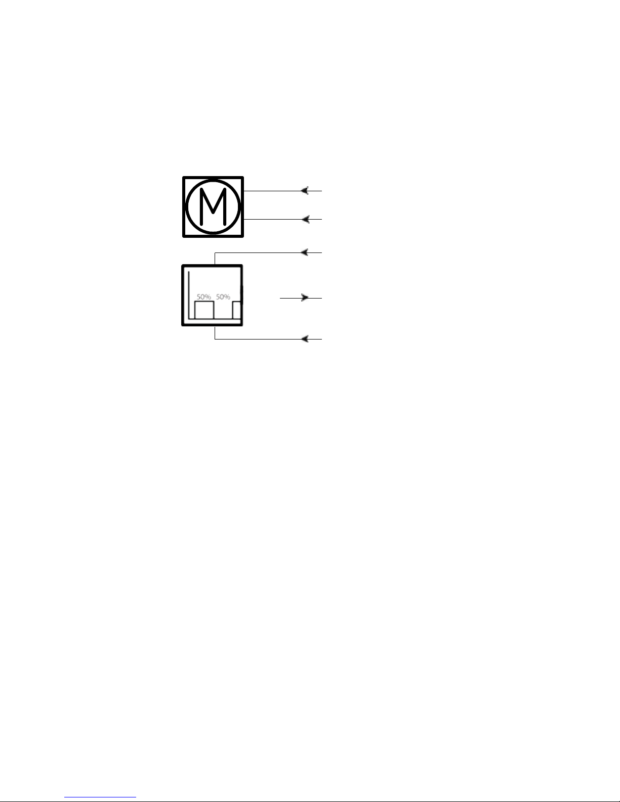
Page 31 of 76
Actuator with absolute positioning - PWM:
Connection diagram:
Fig. 11 : 36xxxxx15/16xxxxxx
36xxxxxxxF00xx-xxxxxxxxxxxxxxx
BROWN
BLUE
PWM
RED
VIOLET
+
BLACK
-
Page 32
Page 32 of 76
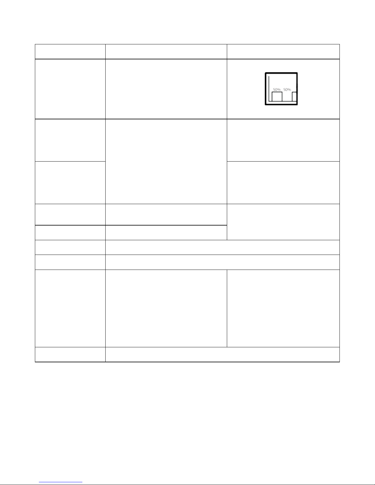
Actuator with absolute positioning - PWM:
I/O specifications:
Input/Output Specification Comments
Description The actuator can be equipped
with electronic circuit that gives an
analogue feedback signal when the
actuator moves.
See connection diagram,
fig. 11, page 31
Brown 12, 24 or 36VDC (+/-)
12V ± 20%
24V ± 10%
36V ± 10%
Under normal conditions:
12V, max. 26A depending on load
24V, max. 13A depending on load
36V, max. 10A depending on load
To extend actuator:
Connect Brown to positive
To retract actuator:
Connect Brown to negative
Blue To extend actuator:
Connect Blue to negative
To retract actuator:
Connect Blue to positive
Red Signal power supply (+)
12-24VDC
Current consumption:
Max. 60mA, also when the
actuator is not running
Black Signal power supply GND (-)
Green Not to be connected
Yellow Not to be connected
Violet Digital output feedback (PNP)
10-90% (Option 5)
20-80% (Option 6)
Output voltage min. V
IN
- 2V
Tolerances +/- 2%
Max. current output: 12mA
Frequency: 75Hz
It is recommendable to have
the actuator to activate its limit
switches on a regular basis, to
ensure more precise positioning
White Not to be connected
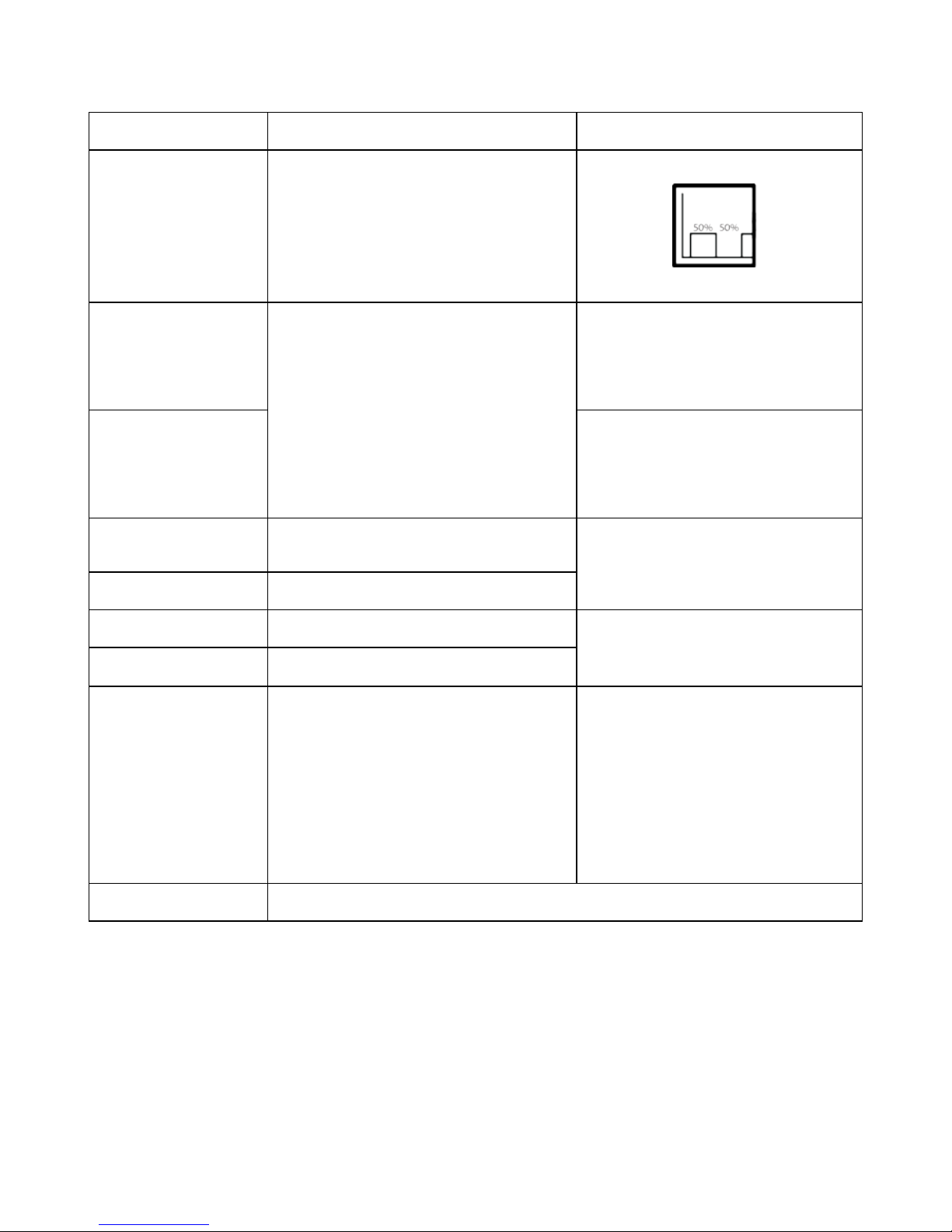
PWM
Page 33
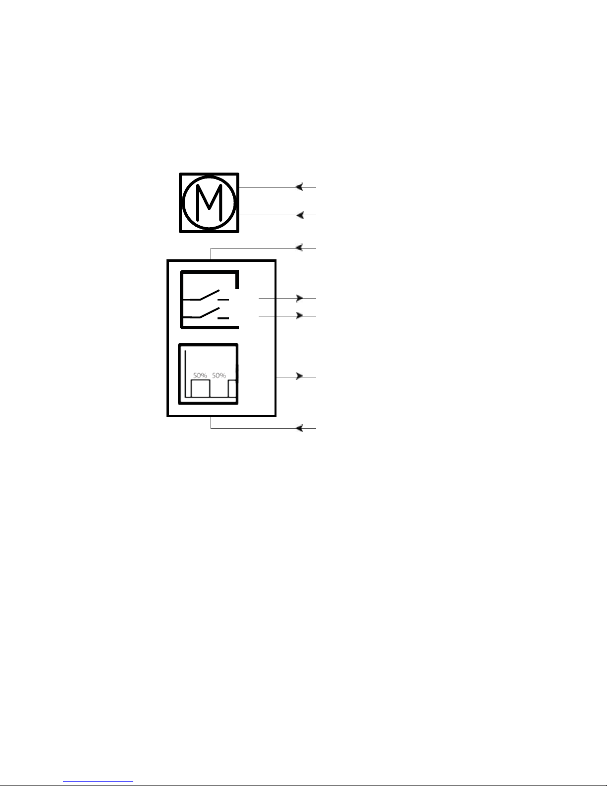
Page 33 of 76
Actuator with endstop signals and absolute positioning - PWM:
Connection diagram:
Fig. 12 : 36xxxxx25/26xxxxxx
36xxxxxxxF00xx-xxxxxxxxxxxxxxx
BROWN
BLUE
PWM
YELLOW*
GREEN*
IN
OUT
RED
VIOLET
+
BLACK
-
*YELLOW/GREEN:
Endstop signals out are NOT potential free!
If you wish to use the endstop signals, you will have to keep power on the brown, blue, red and
black wires, otherwise the signal will be lost.
Page 34
Page 34 of 76
Actuator with endstop signals and absolute positioning - PWM:
I/O specifications:
Input/Output Specification Comments
Description The actuator can be equipped
with electronic circuit that gives an
analogue feedback signal when the
actuator moves.
See connection diagram,
fig. 12, page 33
Brown 12, 24 or 36VDC (+/-)
12V ± 20%
24V ± 10%
36V ± 10%
Under normal conditions:
12V, max. 26A depending on load
24V, max. 13A depending on load
36V, max. 10A depending on load
To extend actuator:
Connect Brown to positive
To retract actuator:
Connect Brown to negative
Blue To extend actuator:
Connect Blue to negative
To retract actuator:
Connect Blue to positive
Red Signal power supply (+)
12-24VDC
Current consumption:
Max. 60mA, also when the
actuator is not running
Black Signal power supply GND (-)
Green Endstop signal out Output voltage min. V
IN
- 2V
Source current max. 100mA
NOT potential free
Yellow Endstop signal in
Violet Digital output feedback (PNP)
10-90% (Option 5)
20-80% (Option 6)
Output voltage min. V
IN
- 2V Tolerances +/- 2%
Max. current output: 12mA
Frequency: 75Hz
It is recommendable to have
the actuator to activate its limit
switches on a regular basis, to
ensure more precise positioning
White Not to be connected
PWM
Page 35
Page 35 of 76
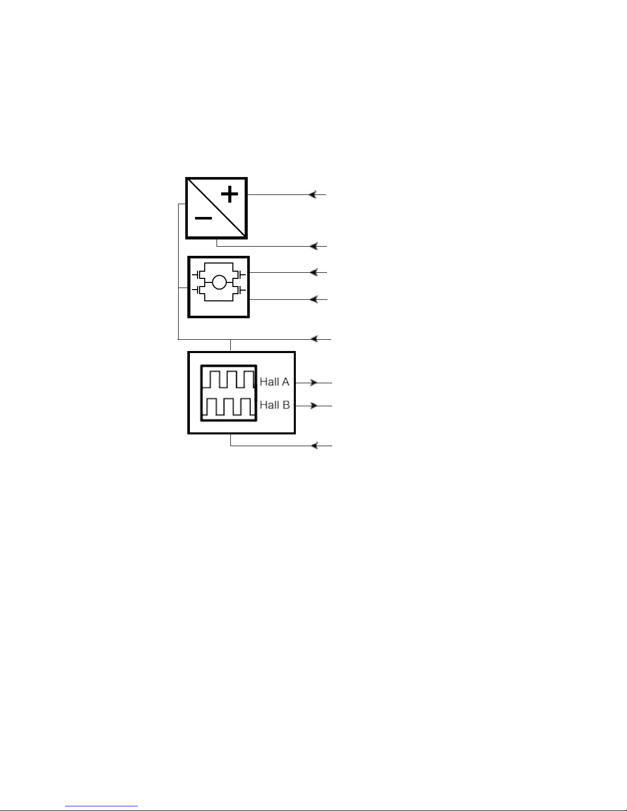
Actuator with old CS36 (H-bridge) version - Dual Hall:
Connection diagram:
Fig. 13 : 36xxxxx30/3Hxxxxxx
BROWN
BLUE
VIOLET
WHITE
INWARDS
OUTWARDS
M
H-Bridge
YELLOW
RED
BLACK
+
-
GREEN
Page 36
Page 36 of 76
Actuator with old CS36 (H-bridge) version - Dual Hall:
I/O specifications:
Input/Output Specification Comments
Description The actuator can be equipped with
old version of integrated controller.
See connection diagram,
fig. 13, page 35
Brown
Only available with 24VDC (+/-)
24V ± 10%
Under normal conditions:
24V, max. 13A depending on load
No current cut-off available
To extend actuator:
Connect Brown to positive
To retract actuator:
Connect Brown to negative
Blue To extend actuator:
Connect Blue to negative
To retract actuator:
Connect Blue to positive
Red Signal power supply (+)
24VDC
Current consumption:
Max. 40mA, also when the
actuator is not running
Black Signal power supply GND (-)
Green Hall B
Current output for Hall output
(PNP) 12mA
Yellow Hall A
Violet Retracts the actuator On/off voltages:
> 67% of V
IN
= ON
< 33% of V
IN
= OFF
Input current: 10mA
White Extends the actuator
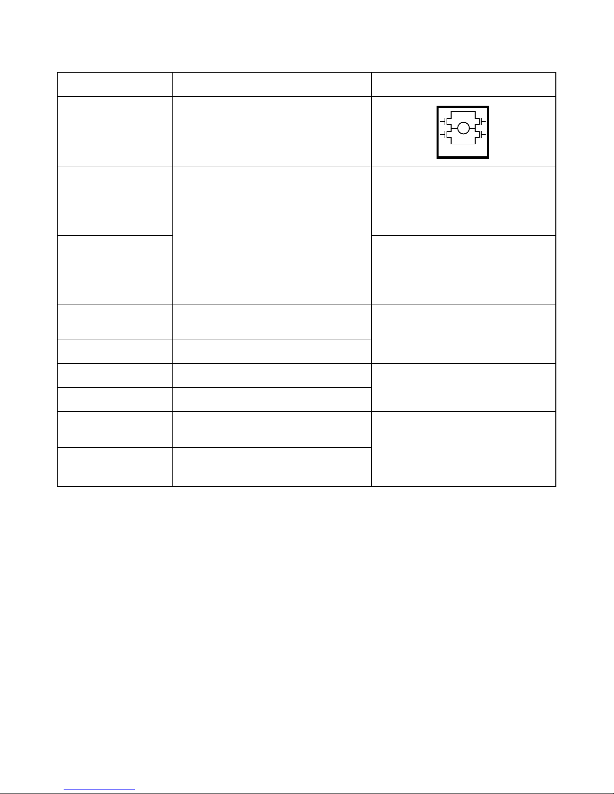
M
H-Bridge
Page 37
Page 37 of 76
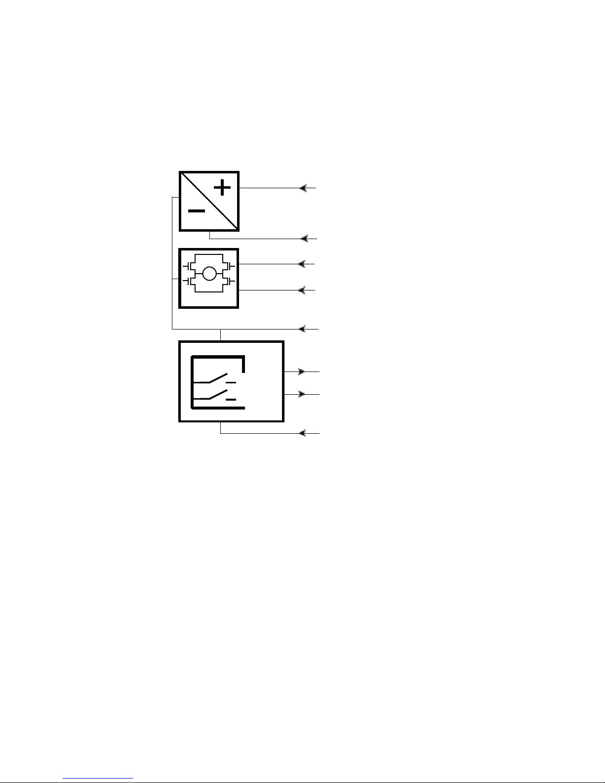
Actuator with old CS36 (H-bridge) version - Endstop signals:
Connection diagram:
Fig. 14 : 36xxxxx40xxxxxx
BROWN
BLUE
VIOLET
WHITE
INWARDS
OUTWARDS
M
H-Bridge
IN
OUT
RED
+
YELLOW*
BLACK
-
GREEN*
*YELLOW/GREEN:
Endstop signals out are NOT potential free!
If you wish to use the endstop signals, you will have to keep power on the brown, blue, red and
black wires, otherwise the signal will be lost.
Page 38
Page 38 of 76
Actuator with old CS36 (H-bridge) version - Endstop signals:
I/O specifications:
Input/Output Specification Comments
Description The actuator can be equipped with
old version of integrated controller.
See connection diagram,
fig. 14, page 37
Brown
Only available with 24VDC (+/-)
24V ± 10%
Under normal conditions:
24V, max. 13A depending on load
No current cut-off available
To extend actuator:
Connect Brown to positive
To retract actuator:
Connect Brown to negative
Blue To extend actuator:
Connect Blue to negative
To retract actuator:
Connect Blue to positive
Red Signal power supply (+)
24VDC
Current consumption:
Max. 40mA, also when the
actuator is not running
Black Signal power supply GND (-)
Green Endstop signal out Output voltage min. V
IN
- 2V
Source current max. 100mA
NOT potential free
Yellow Endstop signal in
Violet Retracts the actuator On/off voltages:
> 67% of V
IN
= ON
< 33% of V
IN
= OFF
Input current: 10mA
White Extends the actuator
M
H-Bridge
Page 39
Page 39 of 76
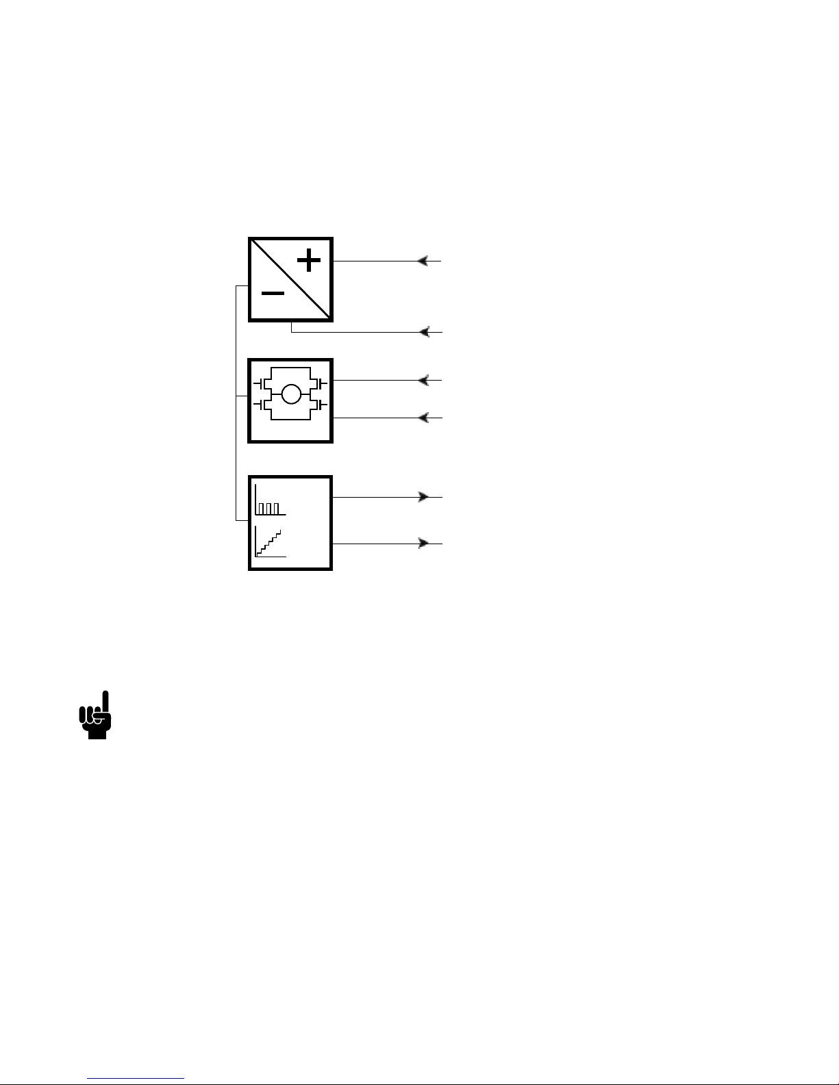
Actuator with IC Basic:
BROWN
BLUE
12/24V DC
Hall
0-10V
WHITE
VIOLET
FEEDBACK
SIGNAL GND
BLACK
RED
INWARDS
OUTWARDS
M
H-Bridge
Connection diagram:
Fig. 15 : 36xxxxx7xxxxxxx
36xxxxxxxx03xx-xxxxxxxxxxxxxxx
Please be aware that if the power supply is not properly connected, you might damage
the actuator!
Page 40
Page 40 of 76
Actuator with IC Basic:
I/O specifications:
Input/Output Specification Comments
Description Easy to use interface with integrated
power electronics (H-bridge).
The actuator can also be equipped
with electronic circuit that gives an
absolute or relative feedback signal.
The version with “IC option”
cannot be operated with PWM
(power supply).
See connection diagram,
fig. 15, page 39
Brown 12-24VDC + (VCC)
Connect Brown to positive
12V ± 20%
24V ± 10%
12V, current limit 25A
24V, current limit 13A
Note: Do not change the power
supply polarity on the brown and
blue wires!
Power supply GND (-) is electrically
connected to the housing
If the temperature drops below
0°C, all current limits will automatically increase to 30A
Blue 12-24VDC - (GND)
Connect Blue to negative
12V ± 20%
24V ± 10%
12V, current limit 25A
24V, current limit 13A
Red Extends the actuator On/off voltages:
> 67% of V
IN
= ON
< 33% of V
IN
= OFF
Input current: 10mA
Black Retracts the actuator
Green Not to be connected
Yellow Not to be connected
M
H-Bridge
Page 41

Page 41 of 76
Actuator with IC Basic:
I/O specifications:
Input/Output Specification Comments
Violet Analogue feedback
0-10V (Option 7.2)
Standby power consumption:
12V, 60mA
24V, 45 mA
Ripple max. 200mV
Transaction delay 20ms
Linear feedback 0.5%
Max. current output: 1mA
It is recommendable to have
the actuator to activate its limit
switches on a regular basis, to
ensure more precise positioning
Single Hall output (PNP) (Option 7.1) Output voltage min. V
IN
- 2V
Max. current output: 12mA
For more information see fig. 5.1,
page 20
White Signal GND For correct wiring of power GND
and Signal GND see page 45
Page 42
Page 42 of 76
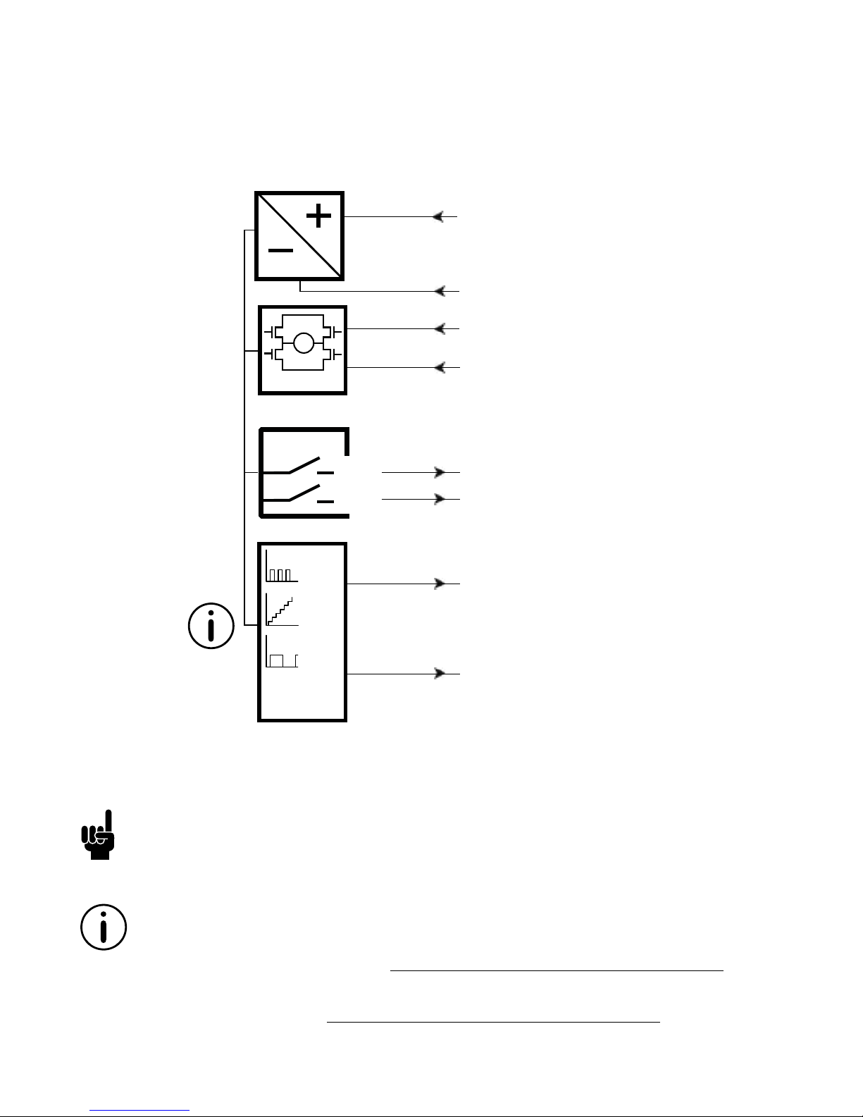
Actuator with IC Advanced - with BusLink:
BusLink is available for IC Advanced and can be used for:
Diagnostics, manual run and configuration
Download BusLink software here: http://www.linak.com/techline/?id3=2363
For more information and easy set-up of BusLink, please follow this link to view the
Quick Guide for BusLink: http://www.linak.com/techline/?id3=2356
BROWN
BLUE
YELLOW
GREEN
WHITE
VIOLET
BLACK
12/24V DC
RED
INWARDS
OUTWARDS
FEEDBACK
SIGNAL GND
M
H-Bridge
IN
OUT
Hall
0-10V
PWM
4-20mA
50%50%
Connection diagram:
Fig. 16 : 36xxxxx8xxxxxxx
36xxxxxxxx03xx-xxxxxxxxxxxxxxx
Please be aware that if the power supply is not properly connected, you might damage
the actuator!
Page 43
Page 43 of 76
Actuator with IC Advanced - with BusLink:
I/O specifications:
Input/Output Specification Comments
Description Easy to use interface with integrated
power electronics (H-bridge).
The actuator can also be equipped
with electronic circuit that gives an
absolute or relative feedback signal.
IC Advanced provides a wide range
of possibilities for customisation.
The version with “IC option” cannot
be operated with PWM (power
supply).
See connection diagram,
fig. 16, page 42
Brown 12-24VDC + (VCC)
Connect Brown to positive
12V ± 20%
24V ± 10%
12V, current limit 25A
24V, current limit 13A
Note: Do not change the power
supply polarity on the brown and
blue wires!
Power supply GND (-) is electrically
connected to the housing
Current limit levels can be
adjusted through BusLink
If the temperature drops below
0°C, all current limits will automatically increase to 30A
Blue 12-24VDC - (GND)
Connect Blue to negative
12V ± 20%
24V ± 10%
12V, current limit 25A
24V, current limit 13A
Red Extends the actuator On/off voltages:
> 67% of V
IN
= ON
< 33% of V
IN
= OFF
Input current: 10mA
Black Retracts the actuator
Green Endstop signal out Output voltage min. V
IN
- 2V
Source current max. 100mA
Endstop signals are NOT potential free. Endstop signals can be
configured with BusLink software
according to any position needed.
Only use one virtual endstop keep one end open for initialisation. (See I/O specifications for
endstop on page 14).
Yellow Endstop signal in
M
H-Bridge
Page 44

Page 44 of 76
Actuator with IC Advanced - with BusLink:
I/O specifications:
Input/Output Specification Comments
Violet Analogue feedback (0-10V):
Configure any high/low
combination between 0-10V
Ripple max. 200mV
Transaction delay 20ms
Linear feedback 0.5%
Max. current output. 1mA
Single Hall output (PNP) Output voltage min. V
IN
- 2V
Max. current output: 12mA
Please be aware that when choos-
ing single hall, feedback position
readout and virtual endstops are
not available in BusLink.
For more information, see fig.
6.1, page 22
Digital output feedback PWM:
Configure any high/low
combination between 0-100%
Output voltage min. V
IN
- 2V
Frequency: 75Hz ± 10Hz as
standard, but this can be
customised.
Duty cycle: Any low/high
combination between 0 and 100
percent.
Open drain source current max.
12mA
Analogue feedback (4-20mA):
Configure any high/low
combination between 4-20mA
Tolerances ± 0.2mA
Transaction delay 20ms
Linear feedback 0.5%
Output: Source
Serial resistance:
12V max. 300 ohm
24V max. 900 ohm
All absolute value feedbacks (0-10V,
PWM and 4-20mA)
Standby power consumption:
12V, 60mA
24V, 45mA
It is recommendable to have
the actuator to activate its limit
switches on a regular basis, to
ensure more precise positioning
White Signal GND For correct wiring of power GND
and Signal GND see page 45
Item numbers for BusLink cables: USB2LIN: USB2LIN05, USB2LIN06 and onwards
Adaptor cable: 0964826-A
Please note that the BusLink cables must be purchased separately from the actuator!
Page 45
Page 45 of 76
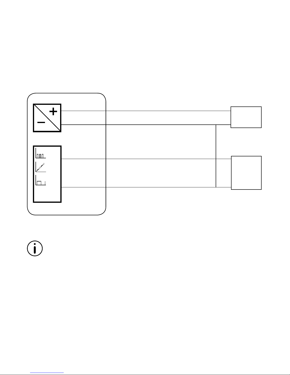
Correct wiring of Power GND and Signal GND
for IC Basic and IC Advanced:
Please note that this section only applies for the following feedback options:
0-10V, Hall and PWM.
When using the feedback output, it is important to use the right connection setup. Attention
should be paid to the two ground connections. Power GND in the Power connector and Signal
GND in the Control connector. When using either 0-10V, Hall or PWM feedback, the Signal GND
must be used. For optimal accuracy, the Signal GND is connected to the Power GND as close as
possible to the feedback input equipment.
FEEDBACK
SIGNAL GND
50%50%
Hall
0-10V
PWM
4-20mA
Power
supply
Feedback
input
Power connector
Control connector
POWER
POWER GND
LA36 IC actuator
WHITE
VIOLET
BROWN
BLUE
Page 46
Page 46 of 76
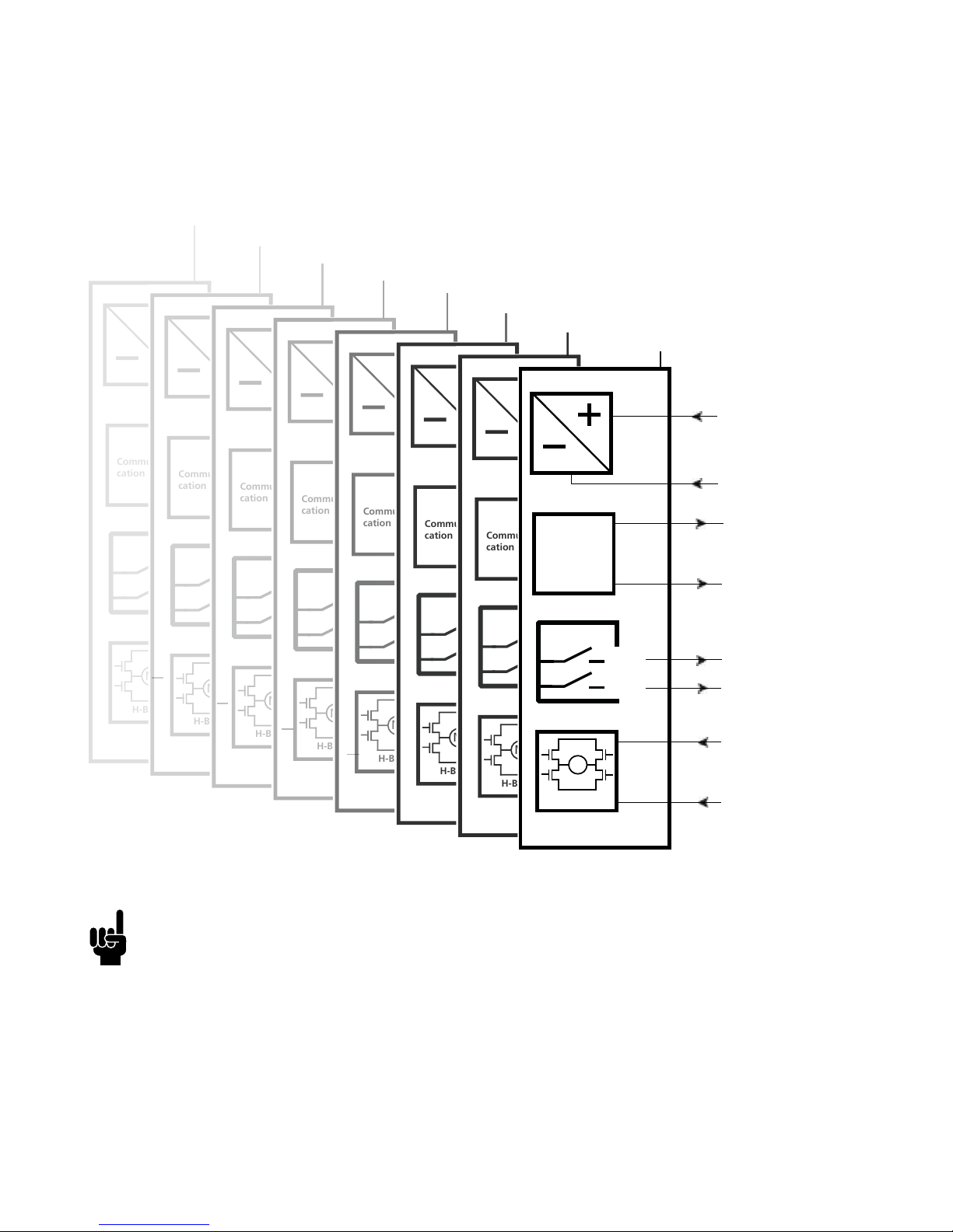
Actuator with Parallel:
• Please be aware that if the power supply is not properly connected, you might
damage the actuator!
• The green and yellow wires from parallel connected actuators must NOT be
interconnected. (See I/O specifications for endstop on page 14).
Connection diagram:
Fig. 17 : 36xxxxx9xxxxxxx
36xxxxxxxx03xx-xxxxxxxxxxxxxxx
Actuator 1
Actuator 2
Actuator 3
Actuator 4
Actuator 5
Actuator 6
Actuator 7
Actuator 8
INWARDS
OUTWARDS
M
H-Bridge
Communi-
cation
IN
OUT
INWARDS
OUTWARDS
M
H-Bridge
Communi-
cation
IN
OUT
INWARDS
OUTWARDS
M
H-Bridge
Communi-
cation
IN
OUT
INWARDS
OUTWARDS
M
H-Bridge
Communi-
cation
IN
OUT
INWARDS
OUTWARDS
M
H-Bridge
Communi-
cation
IN
OUT
INWARDS
OUTWARDS
M
H-Bridge
Communi-
cation
IN
OUT
INWARDS
OUTWARDS
M
H-Bridge
Communi-
cation
IN
OUT
12/24V DC
BLACK
RED
INWARDS
OUTWARDS
M
H-Bridge
BROWN
Communication
WHITE
VIOLET
YELLOW
GREEN
IN
OUT
BLUE
Page 47
Page 47 of 76
Actuator with Parallel:
I/O specifications:
Input/Output Specification Comments
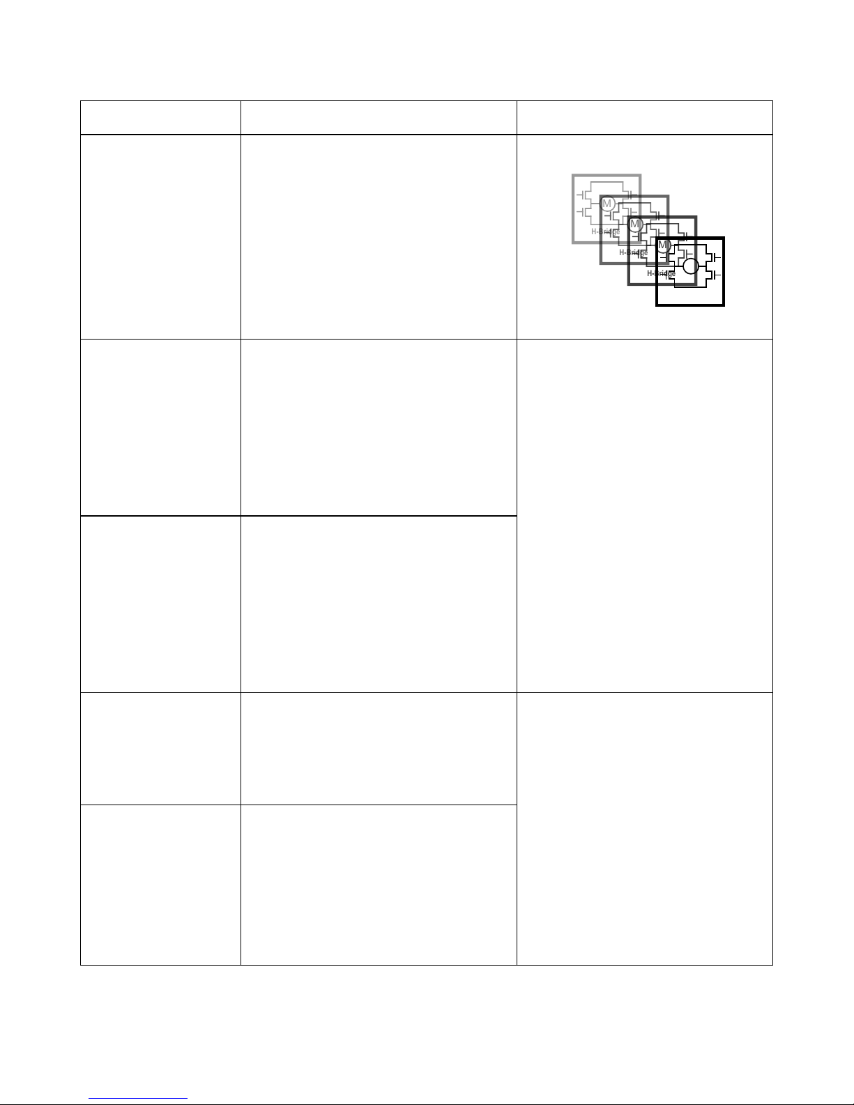
Description Parallel drive of up to 8 actuators. A
master actuator with an integrated
H-bridge controller controls up to 7
slaves.
The version with “IC option”
cannot be operated with PWM
(power supply).
See connection diagram,
fig. 17, page 46
Brown 12-24VDC + (VCC)
Connect Brown to positive
12V ± 20%
24V ± 10%
12V, current limit 25A
24V, current limit 13A
Note: Do not change the power
supply polarity on the brown and
blue wires!
The parallel actuators can run on
one OR separate power supplies
Power supply GND (-) is
electrically connected to the
housing
Current limit levels can be
adjusted through BusLink (only
one actuator at a time for
parallel)
If the temperature drops below
0°C, all current limits will
automatically increase to 30A
Blue 12-24VDC - (GND)
Connect Blue to negative
12V ± 20%
24V ± 10%
12V, current limit 25A
24V, current limit 13A
Red Extends the actuator On/off voltages:
> 67% of V
IN
= ON
< 33% of V
IN
= OFF
Input current: 10mA
It does not matter where the in/
out signals are applied. You can
either choose to connect the
signal cable to one actuator OR
you can choose to connect the
signal cable to each actuator
on the line. Either way this will
ensure parallel drive
Black Retracts the actuator
M
H-Bridge
M
H-Bridge
M
H-Bridge
M
H-Bridge
Page 48

Page 48 of 76
Actuator with Parallel:
I/O specifications:
Input/Output Specification Comments
Green Endstop signal out Output voltage min. V
IN
- 2V
Source current max. 100mA
NOT potential free
Yellow Endstop signal in
Violet Parallel communication:
Violet cords must be connected
together
Standby power consumption:
12V, 60mA
24V, 45mA
No feedback available during
parallel drive
White Signal GND:
White cords must be connected
together
For correct wiring of power GND
and Signal GND see page 45
Page 49
Page 49 of 76
The parallel system:
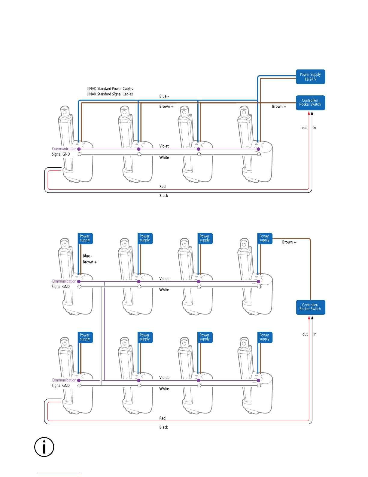
It is both possible to run parallel with a single power supply, or to run each actuator with separate
power supplies.
The parallel drive function will support a number of actuators working jointly.
The system is self-configurable and when connected, a Master will be dedicated.
The Master will then control up to 7 slaves.
Only standard power and signal cables are available for parallel.
Page 50

Page 50 of 76
• The system does not have to run on one power supply only – it can be supplied with several
power supplies
• It does not matter where the IN/OUT signal is applied. The signals of all actuators can be
connected together
• If an overload occurs, the running of the actuators will be stopped and blocked in that direction,
until an activation in the opposite direction has been made or the system has been powered up
again
• When all actuators are connected, a Master will be chosen. E.g. with 5 actuators in one system
there will be 1 Master and 4 Slaves
• Actuators will be pre-programmed from our production as 2, 3, 4, 5 parallel systems etc.
You will not be able to add or remove actuators to/from the system, since they will always run in
accordance with their programming
• In case one of the actuators are broken, the system will not move; not even after re-powering.
The broken actuator needs to be replaced, before the system can run again. The system will only
run, when it is complete
• If you need to add an additional actuator to the parallel system, please contact your local LINAK
supplier. The system will need to be re-programmed
BusLink is available for Parallel
• BusLink can be used for diagnostics
• Parallel can be connected to BusLink – one at a time!
• Service counter is available with Parallel
• Parallel actuator configurations can be changed through BusLink, but all actuators need the
same configurations!
Download BusLink software here: http://www.linak.com/techline/?id3=2363
For more information and easy set-up of BusLink, please follow this link to view the Quick Guide
for BusLink: http://www.linak.com/techline/?id3=2356
Item numbers for BusLink cables:
USB2LIN: USB2LIN05, USB2LIN06 and onwards
Adaptor cable: 0964826-A
Please note that the BusLink cables must be purchased separately from the actuator!
The parallel system:
Page 51
Page 51 of 76
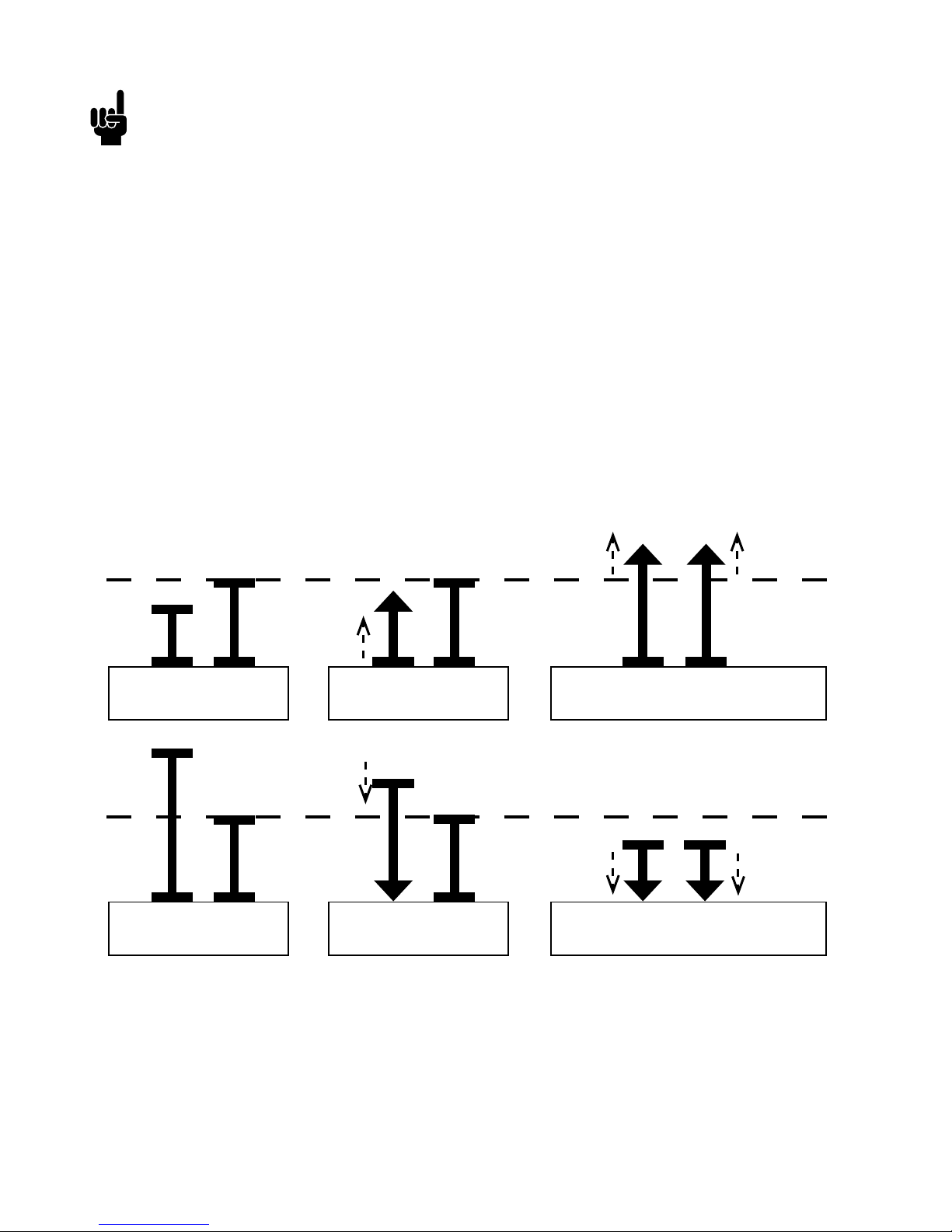
If the actuators are not in parallel when starting up, the next movement will run in the following
manner:
System Monitoring for Parallel
If one of the actuators have one of the following error conditions, the actuator will
immediately STOP:
• H-Bridge fault
• Out of the temperature range (High duty cycle protection)
• Overcurrent (Current cut-off if one or all actuators go in mechanical block)
• SMPS fault
• EOS fault switch
• Hall sensor failure
• Position lost
• Overvoltage (43V DC)
Alignment of the parallel actuator system
Start position
Running outwards
When completely aligned, the
parallel run continues outwards
Start position
Running inwards
When completely aligned, the
parallel run continues inwards
Page 52

Page 52 of 76
Troubleshooting:
Chapter 3
Symptom Possible cause Action
No motor sound or
movement of piston
rod
The actuator is not properly
connected to the power supply
Customer fuse burned
Cable damaged
IC:
Wrongly connected:
+ Brown, - Blue
Signal required for moving
outwards: + VCC -> RED Wire
Signal required for moving
inwards: + VCC -> Black Wire
• Check the connection to the
power supply or the external
control unit (if any)
To extend actuator:
Connect Brown to positive and
Blue to negative
To retract actuator:
Connect Brown to negative and
Blue to positive
• Change cable
• Check wire connection (Red/
Black) on control unit
• Please contact LINAK
Excessive electricity
Consumption
Misalignment or overload in
application
• Align or reduce load
• Try to run the actuator without
load
• Please contact LINAK
Motor runs but
spindle does not
move
Gearing system or spindle
damaged
• Please contact LINAK
Actuator cannot lift
full load
Clutch is worn
Motor is damaged
Insufficient power supply
IC: Current cut off (overload in
application)
• Align or reduce load
• Check power supply
IC (for IC advanced and Parallel
only): Connect actuator to
BusLink and check the current
parameters (inwards/outwards)
• Please contact LINAK
Page 53

Page 53 of 76
Troubleshooting:
Symptom Possible cause Action
No signal from
Feedback
Wrongly Connected:
Violet: Signal out
White: Signal GND
Yellow: Endstop In
Green: Endstop Out
Cable damaged
Bad connection
Potentiometer damaged
Hall sensor or magnet damaged
IC (for IC Advanced only):
Check Feedback option - connect
to BusLink
• Check wiring
• Change cable
IC (for IC Advanced only):
Connect actuator to BusLink and
check current parameters.
Initialise the actuator in both
directions
• Please contact LINAK
Motor runs too slowly
or does not run with
full force
Motor runs in smaller
steps
Load is higher than specified
Voltage drop in cable (Use of long
cables can negatively affect the
performance of the actuator)
Insufficient power supply
IC: Current Cut-off
• Reduce load
• Check power supply
IC: Connect actuator to BusLink
and check current parameters
(reason for last stop)
Actuator(s) cannot
hold the chosen load
Load is higher than specified • Reduce load
Page 54

Page 54 of 76
Troubleshooting for Parallel:
Symptom Possible cause Action
No actuators in
movement
Power supply • Check power supply source and
power connections:
Brown +
Blue -
Please be aware that if the
power supply is not properly
connected, you might damage
the actuator
Signal connections • Check parallel communications:
Violet = Communication
Violet cords must be connected
together
White = Signal GND
White cords must be connected
together
Signal required for moving
outwards: + VCC (Red wire)
Signal required for moving
inwards: + VCC (Black wire)
• Check wire connection (Red/
Black) on control unit
• Put power on all actuators at the same time, after everything is
connected. Then wait 10 seconds before signals for moving In/Out are
activated
Actuator(s) cannot lift
full load
Load is higher than specified • Reduce load
• Check for sufficient power
supply current
• Connect actuator via BusLink
one at the time and check
monitoring for each actuator
(reason for last stop)
Short movements
before stops
Actuator NOT connected properly
Violet = Parallel communication
White = Signal GND
• Check wire connection (Violet/
White)
• If OK - Connect actuators via
BusLink one at the time and check
monitoring for each actuator
(reason for last stop)
Page 55

Page 55 of 76
Troubleshooting for Parallel:
Symptom Possible cause Action
Signal cable damaged
or removed under
operation
All actuators stop at the same
position
• When seeing a communication
error, the system goes into
‘position lost’
• The signal and power cables
MUST be connected to all
actuators again
• Afterwards, the Parallel system
needs re-powering
• If one actuator is missing, the
system will not work, not even
after re-powering
BusLink monitoring:
Reason for last stop
H-bridge fault
SMPS fault
• Please contact your local
supplier for further instructions
Overcurrent • The Parallel system cannot
continue in the same direction
• Reactivation is needed in the
opposite direction
EOS OUT error
EOS IN error
• The Parallel system stops at
the same time. When seeing an
EOS error, the actuator goes into
‘position lost’, and the system will
need initialisation (to initialise,
move the actuators into fully
retracted position)
Hall error • The system stops at the same
position. When seeing hall error,
the actuator goes into ‘position
lost’, and the system will need
initialisation (to initialise, move
the actuators into fully retracted
position)
Out of range temperature for
ambient location
Out of range temperature at FET
location
The above can be due to high
environment temperature or high
duty cycle
• The error causes the actuators to
stop. After elimination of the error
(cooling down) and reactivation of
the movement, the actuators will
move normally
• This may not be used for stop of
the system
Page 56
Page 56 of 76
Troubleshooting for Parallel:
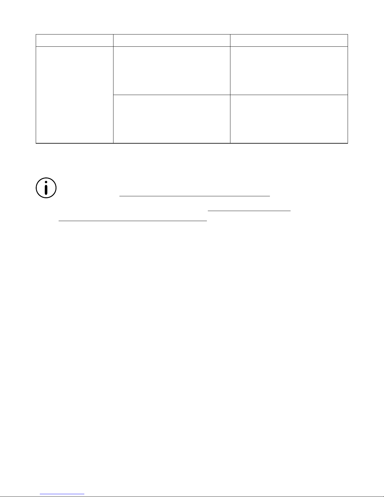
Symptom Possible cause Action
BusLink monitoring:
Reason for last stop
Overvoltage • When seeing overvoltage, the
system stops at the same time.
The system needs re-powering
and In/Out signals must be
removed before next movement
Undervoltage • When seeing undervoltage, the
system stops at the same time.
The system needs re-powering
and In/Out signals must be
removed before next movement
For more information and easy set-up of BusLink, please follow this link to view the Quick
Guide for BusLink: http://www.linak.com/techline/?id3=2356
Be aware of Modbus actuator - please see the Modbus installation guide.
http://www.linak.com/techline/?id3=2363
Page 57

Page 57 of 76
Specifications
Motor: Permanent magnet motor 12, 24, or 36V *
Cable: Motor: 2 x 14 AWG PVC cable
Control: 6 x 20 AWG PVC cable **
Gear ratio: 6 different gear ratios available in steel
(500 N, 1,700/2,600 N, 4,500 N, and 6,800/10,000 N)
Slip clutch: Mechanical overload protection through an integrated slip clutch
Brake: Integrated brake ensures a high self-locking ability.
The brake is deactivated when the actuator is powered in order to
obtain a high efficiency
Hand crank: As a standard feature the actuator can be operated manually
Housing: The housing is made of casted aluminium, coated for outdoor use and
in harsh conditions
Spindle part: Outer tube: Extruded aluminium anodised
Inner tube: Stainless steel AISi304/SS2333
Acme spindle: Trapezoidal spindle with high efficiency
Temperature range: - 30
o
C to +65o C
- 22
o
F to +150o F
Full performance +5o C to +40o C
End play: 2 mm maximum
Weather protection: Rated IP66 for outdoor use. Furthermore, the actuator can be washed
down with a high-pressure cleaner (IP69K).
Usage:
• The duty cycle at max. load is 20% on time. This means if the actuator runs continuously for
20 seconds it must remain off for 80 seconds before operating again.
NB. At 10,000 N only 5%
• Safety device regarding functional failure of the nut (Safety nut):
The LA36 has a built-in safety nut in push as an option. Actuators with safety nut in push can
only function when used in push applications. The safety nut comes into operation should the
main nut fail. Afterwards it is only possible to drive the actuator into the innermost position.
Thereafter, the actuator will not function any more and must be sent for service.
* Modbus actuators only 24V - please see the
Modbus installation guide http://www.linak.com/techline/?id3=2363
** Special control cabels for the Modbus actuator - please see the
Modbus installation guide http://www.linak.com/techline/?id3=2363
Chapter 4
Page 58
Page 58 of 76
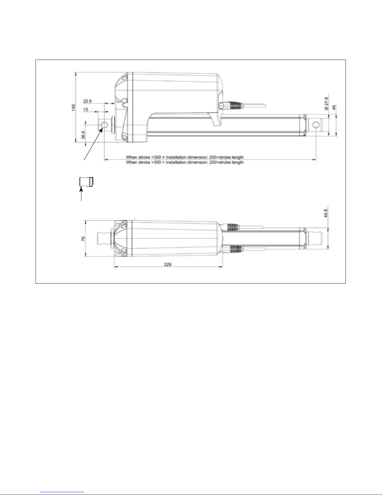
TECHLINE® LA36:
Actuator dimensions
_
02= Turned 90°
01= Standard
Page 59
Page 59 of 76
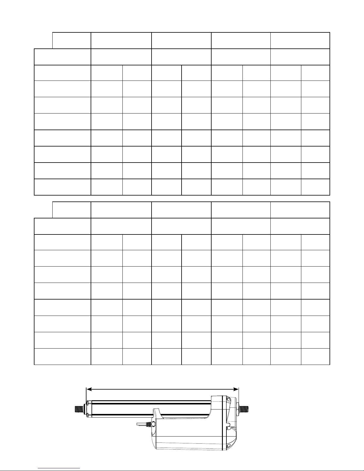
Built-in dimensions
* These built-in dimensions are measured according to the illustration below.
Built-in dimensions
Piston rod “0” /from the surface “1” / to the centre of
the hole
“2” / to the centre of
the hole
“3” / from the surface
Back fixture Stroke <=300 Stroke
> 300
Stroke <=300 Stroke
> 300
Stroke <=300 Stroke
> 300
Stroke <=300 Stroke
> 300
“0” / from the surface 189 239 194 244 194 244 181 231
“1” and “2” / to the
centre of the hole
195 245 200 250 200 250 187 237
“3” and “4” / to the
centre of the hole
195 245 200 250 200 250 187 237
“5” / from the surface 180 230 185 235 185 235 173 223
“6” / from the surface 180 230 185 235 185 235 173 223
“7” and “8” / to the
centre of the hole
195 245 200 250 200 250 187 237
“A” and “B” / to the
centre of the hole
195 245 200 250 200 250 187 237
“C” and “D” / to the
centre of the hole
195 245 200 250 200 250 187 237
Piston rod “4” /from the surface “5” / to the centre of
the hole
“C” / to the centre of
the hole
“D” / from the surface
Back fixture Stroke <=300 Stroke
> 300
Stroke <=300 Stroke
> 300
Stroke <=300 Stroke
> 300
Stroke <=300 Stroke
> 300
“0” / from the surface 181 231 194 244 209 259 209 259
“1” and “2” / to the
centre of the hole
187 237 200 250 215 265 215 265
“3” and “4” / to the
centre of the hole
187 237 200 250 215 265 215 265
“5” / from the surface 172 222 185 235 200 250 200 250
“6” / from the surface 172* 222* 185 235 200 250 200 250
“7” and “8” / to the
centre of the hole
187 237 200 250 215 265 215 265
“A” and “B” / to the
centre of the hole
187 237 200 250 215 265 215 265
“C” and “D” / to the
centre of the hole
187 237 200 250 215 265 215 265
Page 60
Page 60 of 76
Manual Hand Crank
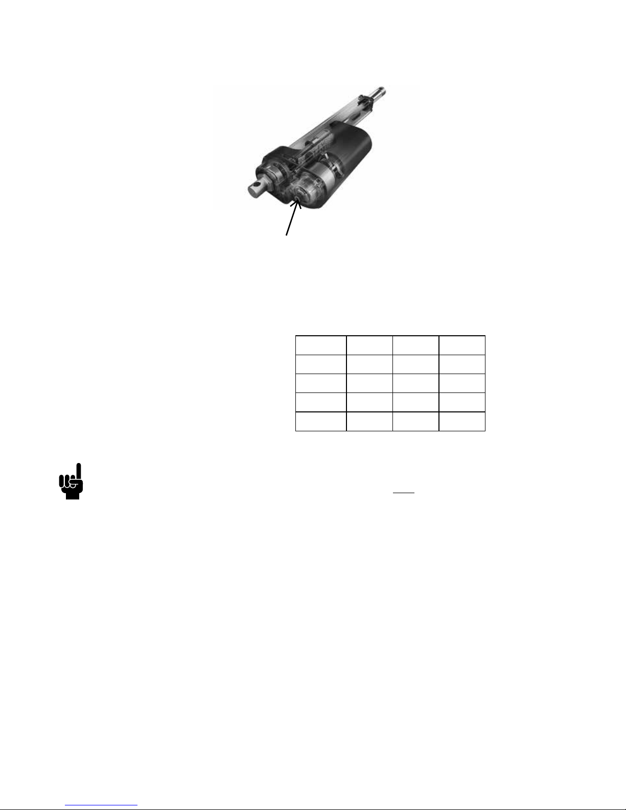
The cover over the Allen key socket must be unscrewed before the Allen key can be
inserted and the hand crank operated.
Hand Crank Torque: 6 - 8 Nm
Piston rod movement per turn, app.:
The manual hand crank can be used in the case of power failure.
• The power supply has to be disconnected during manual operation
• If the actuator is operated as a Hand crank, it must only be operated by hand,
otherwise there is a potential risk of overloading and hereby damaging the actuator.
6 mm Allen key
8 mm 12 mm 20 mm
Gear A - 11 mm 18 mm
Gear B - 6 mm 10 mm
Gear C 3 mm 4 mm 7 mm
Gear F - - 27 mm
Page 61
Page 61 of 76
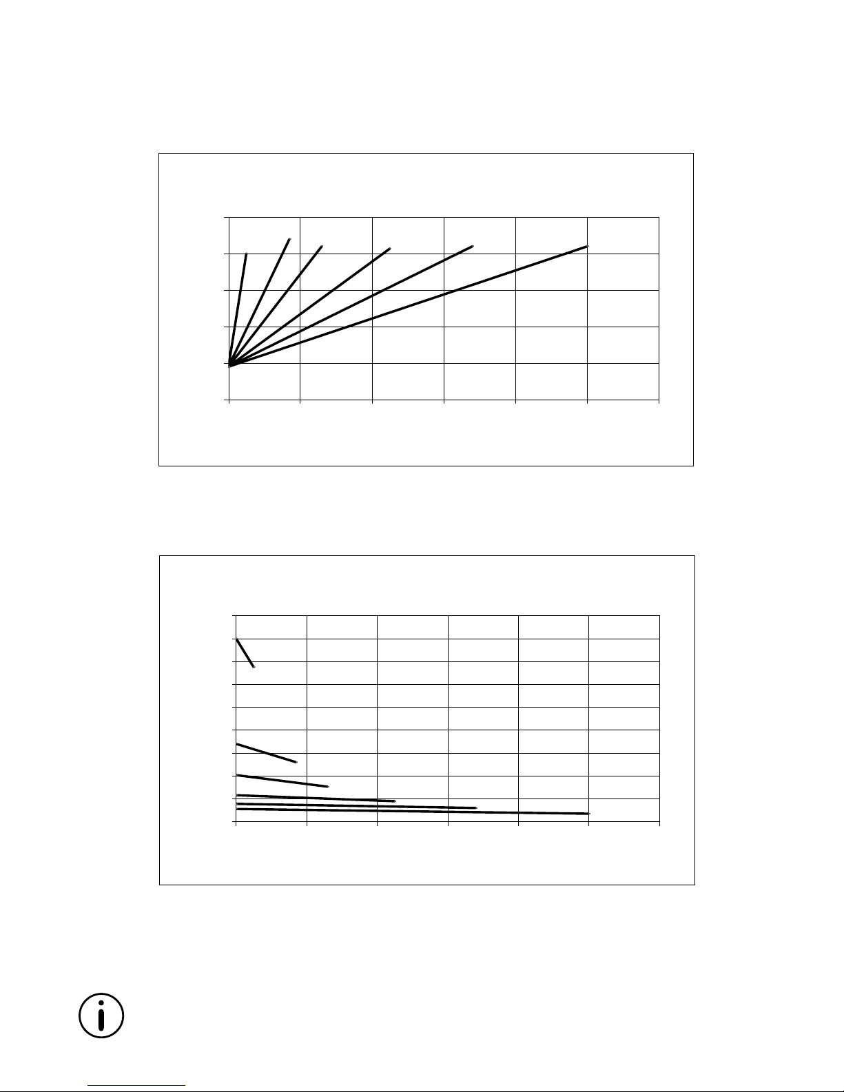
Speed and current curves - 12V motor
0
5
10
15
20
25
0 2000 4000 6000 8000 10000 12000
Ampere
Load (N)
LA36 12V motor current vs. load
8mm/
H gear
12mm/
G gear
12mm/
H gear
20mm/
F gear
12mm/
F gear
20mm/
E gear
0
20
40
60
80
100
120
140
160
180
0 2000 4000 6000 8000 10000 12000
Speed (mm/s)
Load (N)
LA36 12V motor speed vs. load
12mm/
F gear
12mm/
G gear
12mm/
H gear
20mm/
F gear
20mm/
E gear
8mm/
H gear
All measurements above describe the spindle pitch (e.g. 20mm) and the gear type
(e.g. E gear) of the actuator.
Speed and current are based on a nominal power supply of 12, 24, 36VDC.
The values below are typical values and made with a stable power supply and an ambient temperature of 20˚C.
Page 62
Page 62 of 76
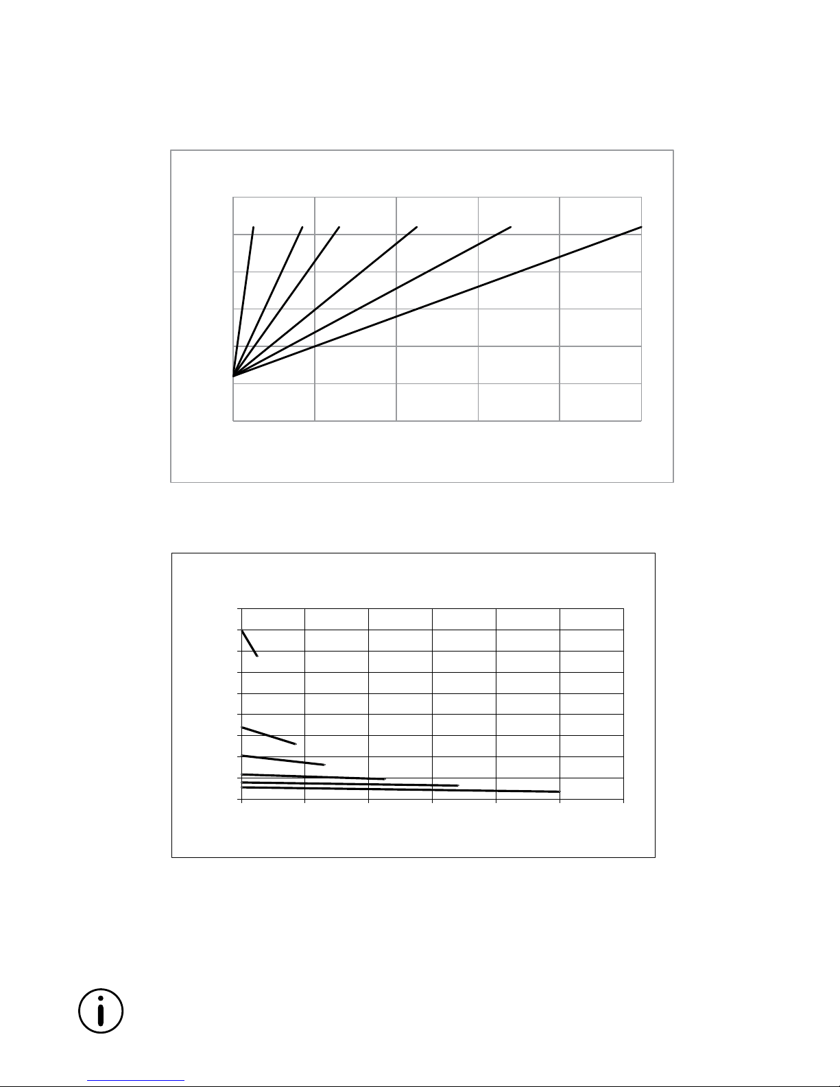
Speed and current curves - 24V motor
All measurements above describe the spindle pitch (e.g. 20mm) and the gear type
(e.g. E gear) of the actuator.
Speed and current are based on a nominal power supply of 12, 24, 36VDC.
The values below are typical values and made with a stable power supply and an ambient temperature of 20˚C.
0
20
40
60
80
100
120
140
160
180
0 2000 4000 6000 8000 10000 12000
Speed (mm/s)
Load (N)
LA36 24V motor speed vs. load
12mm/
F gear
12mm/
G gear
12mm/
H gear
20mm/
F gear
20mm/
E gear
8mm/
H gear
0
2
4
6
8
10
12
0 2000 4000 6000 8000 10000
Ampere
Load (N)
LA36 24V motor current vs. load
8mm/
H gear
12mm/
H gear
12mm/
G gear
12mm/
F gear
20mm/
F gear
20mm
E gear
Page 63
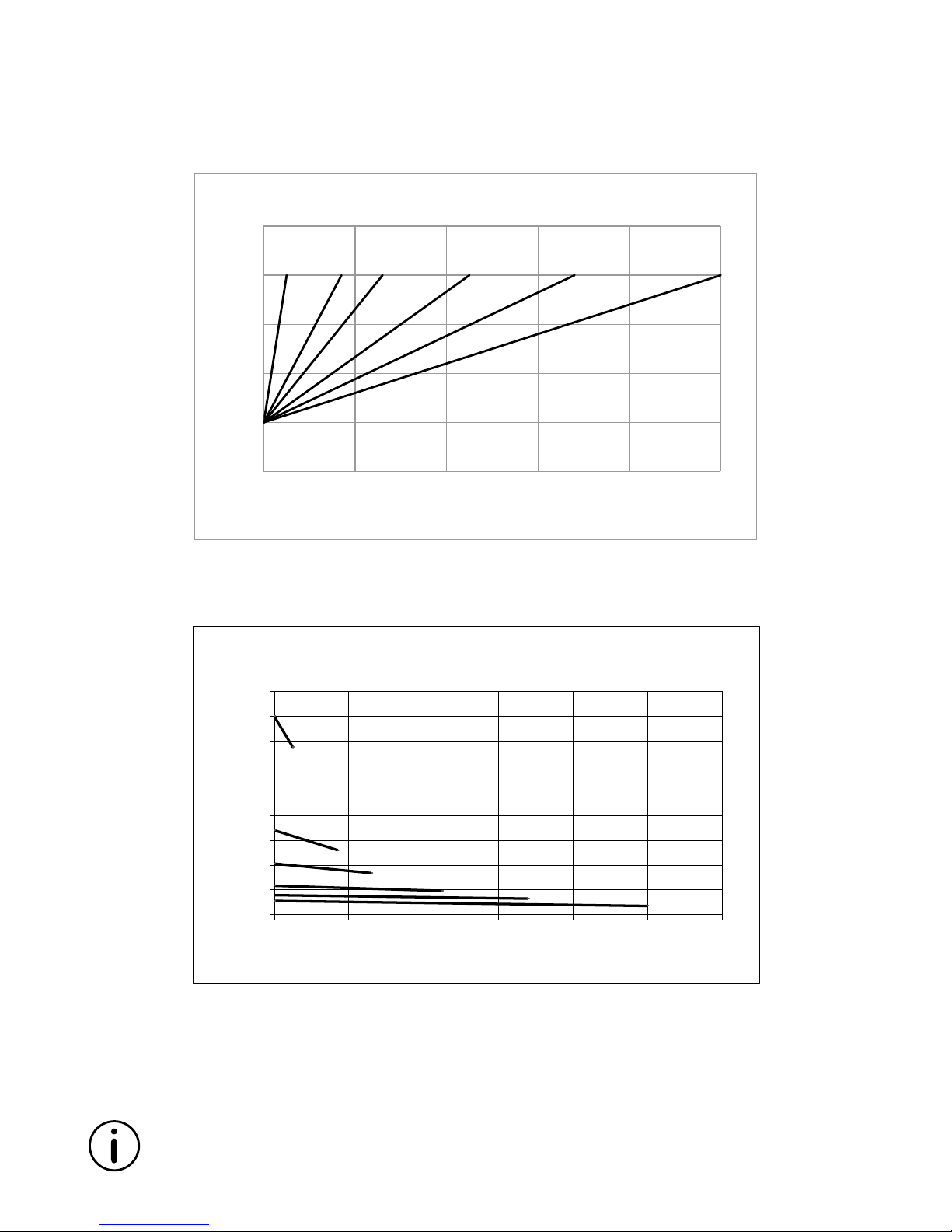
Page 63 of 76
Speed and current curves - 36V motor
All measurements above describe the spindle pitch (e.g. 20mm) and the gear type
(e.g. E gear) of the actuator.
Speed and current are based on a nominal power supply of 12, 24, 36VDC.
The values below are typical values and made with a stable power supply and an ambient temperature of 20˚C.
0
2
4
6
8
10
0 2000 4000 6000 8000 10000
Ampere
Load (N)
LA36 36V motor current vs. load
8mm/
H gear
12mm/
H gear
12mm/
G gear
12mm/
F gear
20mm/
F gear
20mm/
E gear
0
20
40
60
80
100
120
140
160
180
0 2000 4000 6000 8000 10000 12000
Speed (mm/s)
Load (N)
LA36 36V motor speed vs. load
12mm/
F gear
12mm/
G gear
12mm/
H gear
20mm/
F gear
20mm/
E gear
8mm/
H gear
Page 64
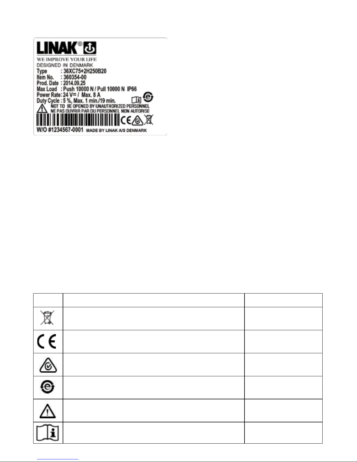
Page 64 of 76
Key to symbols:
The following symbols are used on the LA36 label:
Symbol Norms Approvals
WEEE Directive 2002/96/EC Wheelie bin
Compliance to all relevant EC directives CE
C-Tick 2002: The Australian EMC C-Tick
China Pollution control mark (also indicates recyclability) China RoHS legislation
ISO 7000- 0434A: Caution
Operating instructions
Label for LA36
4. Max Load.: Push 10000N / Pull 10000N IP66
Describes the maximum load that the product can be exposed to in compression and tension.
This line also contains a reference to the product’s IP protection degree
5. Power Rate.: 24VDC / Max. 8 Amp
Input voltage for the product and maximum current consumption
6. Duty Cycle.: 5%, Max. 1 min./19 min.
The duty cycle defines the maximum period during operation without interruption. After
operation, a pause must be observed. It is important that the operator follows the instructions
of the duty cycle; otherwise, a possible overload may result in reduced product life/errors
7. W/O #1234567-0001
The LINAK work order followed by a unique sequential identification number
1. Type.: 36XC75+2H250B20
Describes the basic functionality of the
product
2. Item no.: 360354-00
Sales and ordering code
3. Prod. Date.: YYYY.MM.DD
Production date describes when the
product has been produced. This date is
the reference for warranty claims
Page 65
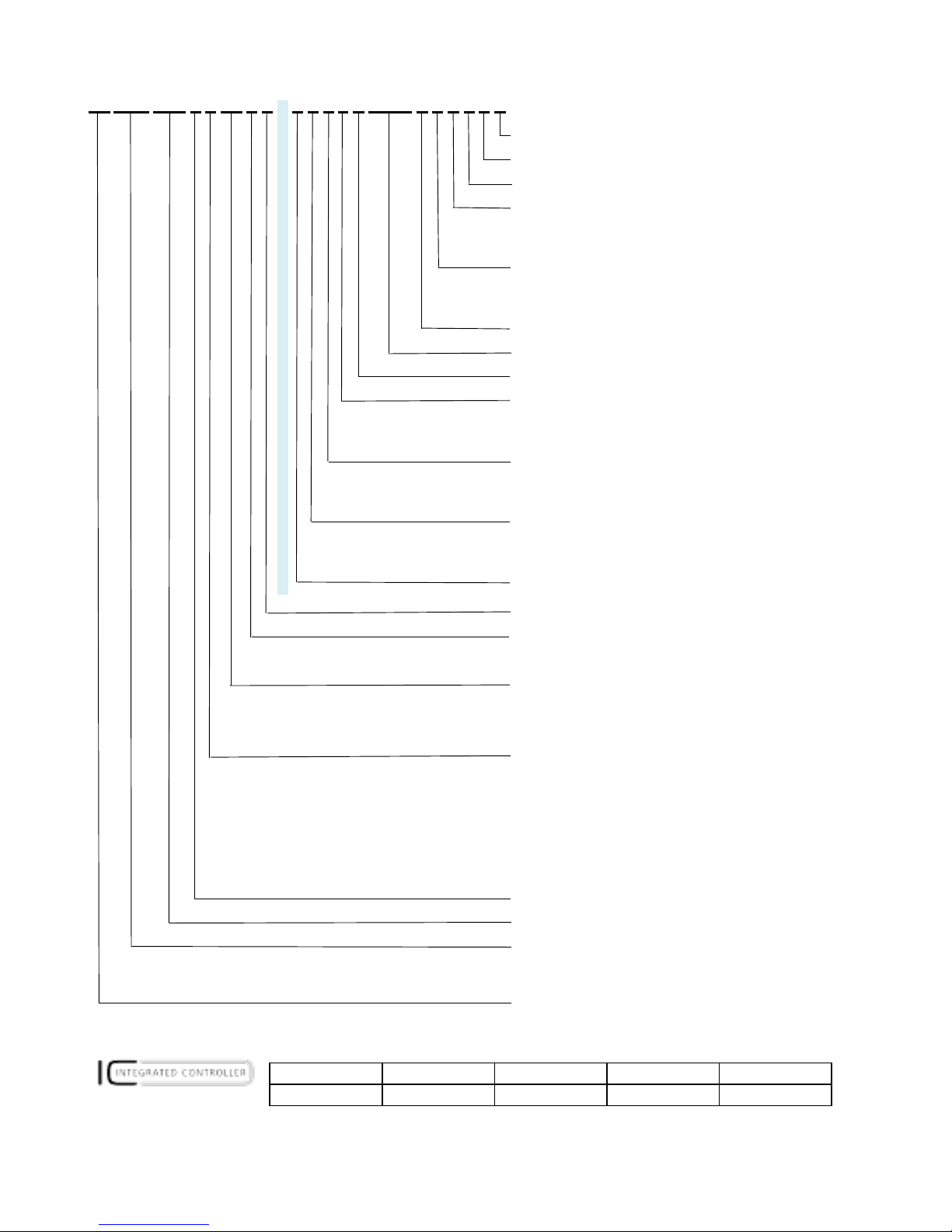
Page 65 of 76
*
LA36
Ordering example Econ
IC options: IC LINbus Modbus Parallel
LA36 actuator:
� � � �
3 6 0 0 1 0 0 0 A P 0 0 0 0 - 6 0 1 0 0 0 2 8 8 2 1 S 0 0 0
Not used 0
Not used 0
Not used
0
Cable: 0 = None
S = Straight
Y = Y-Cable
X = Special
Plug Type:
C = Flying leads
J = Deutsch (DT)
X = Special
Not used: 0
Install. Dim.: XXXX = mm
Brake:
3 = Brake (push/pull)
Option Position: E = Gear ratio 1:7
F = Gear ratio 1:18
G = Gear ratio 1:31
H = Gear ratio 1:46
Piston Rod Eye: 1 = With slot 4 = Outer thread
2 = Solid
5 = Inner thread
6 = Ball eye
X = Special
Back fixture: 1 = 0 degrees 4 = Outer thread
2 = 90 degrees 5 = Inner thread
6 = Rotated (interval 30° )
X = Special
Colour:
6 = Dark Olivish Grey NCS S7000-N
X = Special
IP:
A = IP66
Motor Type: A = 12VDC. Normal 1 = 12VDC. With dummy clutch
B = 24VDC. Normal 2 = 24VDC. With dummy clutch
C = 36VDC. Normal 3 = 36VDC. With dummy clutch
*Platform: 00 = Standard (None)
03 = IC integrated control
04 = MODBUS
06 = LINBUS
XX = Special
Feedback: 0 = None
A = Hall Potentiometer (only IC)
B = Analogue 0-10V (only standard)
C = Analogue 0.5-4.5V (only standard)
D = MODBUS (only IC)
F = PWM
H = Dual Hall (only Standard)
K = Single Hall
P = Potmeter (only standard)
Z = Hall and potentiometer (only standard and special items)
X = Special
Safety : A = Safety nut
Stroke Length:
XXX = mm.
Spindle Pitch: 080 = 8 mm
120 = 12 mm
200 = 20 mm
Actuator Type:
36 = LA36
H = AMP
Page 66
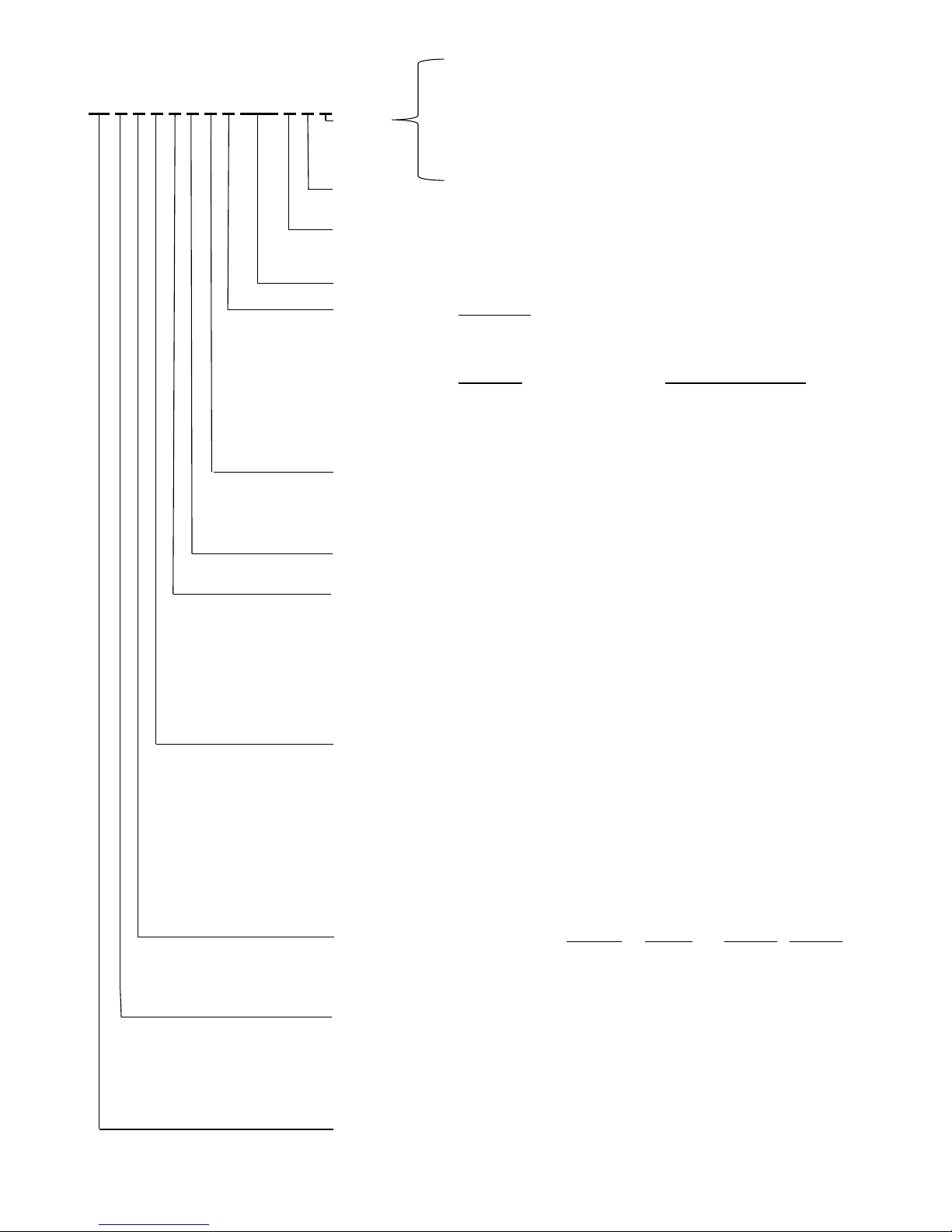
Page 66 of 76
0 = No cable
COMBINATION CODE NOS. LA36
1 = 1.5 m power cable (0367046-1500)
2 = 5 m power cable (0367046-5000)
36 0 0 0 0 + 0 0 0 0 0 0 0 0
3 = 0.2 m power cable with AMP connector (0367006)
CABLE:
4 = 1.5 m power and 1,5 signal (0367046-1500+0367049-1500)
5 = 5 m power and 5 m signal (0367046-5000+0367049-5000)
6 = 1.5 m Y-cable, power and signal in one (0367020)
7 = 5 m power Cable + Data cable M12x1 (Bus)
IP-DEGREE:
2 = Standard (IP66)
8 = IP66 ATEX / IECEx approved
MOTOR TYPE:
A = 12 V DC with clutch
1 = 12 V DC with dummy clutch (as standard only with IC)
B = 24 V DC with clutch
2 = 24 V DC with dummy clutch (as standard only with IC)
C = 36 V DC with clutch
STROKE LENGTH:
XXX = mm Acme spindle: 100, 150....999 mm
FEEDBACK:
Standard and IC:
0 = Standard (No feedback)
5 = PWM 10-90%
6 = PWM 20-80%
Only standard:
Only IC:
B = Analogue feedback 0 - 10V D = Bus
C = Analogue feedback 0.5 - 4.5V
1 = Single Hall
H = Dual Hall
2 = Analogue feedback 0-10V
P = Potentiometer 3 = Analogue feedback 0.5-4.5V
K = Single hall 4 = Analogue feedback 4-20 mA
END STOP:
0 = With out limt switches 7 = IC Basic
1 = With limt switches
8 = IC Advanced
2 = With limt switches and end-stop signals
9 = Parallel
A = Modbus (Special article number only)
B = LINBUS
SAFETY NUT
+ = Standard
S = With safety nut - only in push
PISTON ROD EYE:
0 = M20 X 1 female adapter 0361016
1 = ø 12.9 mm hole, for 1/2" pin 0361018-B
2 = ø 12.2 mm hole, for 12 mm pin 0361109-B
3 = M12 X 1.75 male adapter 0361224
4 = M16 X 1.5 male adapter 0361135
5 = ø 12.2 hole with slot (Like LA34) 0361138
A = ø 12.2 hole with slot AISI 304 0361260
B = ø 12.9 hole with slot AISI 304 0361275
C = ø 12 H7 Ball Eye AISI 304 0361350
D = ø 16 H7 Ball Eye AISI 304 0361351
BACK FIXTURE:
0 = M20 X 1 female adapter 0361128
1 = ø 12.9 mm hole, for 1/2" pin 0361129
2 = ø 12.9 mm hole turned 90°, for 1/2" pin 0361129
3 = ø 12.2 mm hole, for 12 mm pin 0361119
4 = ø 12.2 mm hole turned 90°, for 12 mm pin 0361119
5 = M12 X 1.75 male adapter 0361126
6 = M16 X 1.5 male adapter 0361247
7 = ø 12.3 hole with slot (Like LA34) 0361140
8 = ø 12.3 hole with slot ( LA34) turned 90° 0361140
A = ø 12.2 hole with slot AISI 304 0361261
B = ø 12.2 hole with slot AISI 304 turned 90° 0361261
C = ø 12.9 hole with slot AISI 304 0361276
D = ø 12.9 hole with slot AISI 304 turned 90° 0361276
GEARBOX:
2.5 mm pitch
8 mm pitch 12 mm pitch 20 mm pitch
A = Gear ratio 1 : 18 N.A. N.A. 2.600 N 1.700 N
B = Gear ratio 1 : 31 N.A. N.A. 4.500 N N.A.
C = Gear ratio 1 : 46 10.000 N 10.000 N 6.800 N N.A.
F = Gear ratio 1 : 7 N.A. N.A. N.A. 500N
SPINDLE TYPE:
1 = 1-threaded acme spindle (2.5 mm pitch)
2 = 2-threaded acme spindle (8 mm pitch)
3 = 3-threaded acme spindle (12 mm pitch)
5 = 5-threaded acme spindle (20 mm pitch)
A = 2 + adjustable reed limit switches (on outer tube)
C = 3 + adjustable reed limit switches (on outer tube)
E = 5 + adjustable reed limit switches (on outer tube)
ACTUATOR TYPE:
36 = LA36
When ordering standard stroke length with endstop 1, 2, 3 or 4 the stroke length will be up to 4 mm shorter.
LA36
Ordering example
Page 67

Page 67 of 76
Maintenance
• The actuator must be cleaned at regular intervals to remove dust and dirt and inspected for
mechanical damages or wear.
• Inspect attachment points, wires, piston rod, cabinet, and plug, as well as check that the
actuator functions correctly.
• To ensure that the pregreased inner tube remains lubricated, the actuator
must only be washed
down when the piston rod is fully retracted.
• The actuator is a closed unit and therefore requires no internal maintenance.
• In order to maintain a proper performance of the spherical eyes and to increase the resistance
against environmental wear, we strongly recommend that the spherical eyes (ball bearings)
mounted on actuators from LINAK are greased with anticorrosive grease or similar.
Repair and spare parts
Repair
Only an authorised LINAK
®
service centre should repair LINAK actuator systems. Systems to be
repaired under warranty must be sent to an authorised LINAK service centre.
In order to avoid the risk of malfunction, all actuator repairs must only be carried out by an
authorised LINAK Service shop or repairer, as special tools and parts must be used.
If a system is opened by unauthorised personel there is a risk that it may malfunction at a later date.
Spare parts
LINAK can supply spindle parts and motor parts as spare parts. Please indicate the designation from
the label when ordering spare parts from your nearest authorised LINAK dealer.
Main groups of disposal
LINAK’s products may be disposed of, possibly by dividing them into different waste groups for
recycling or combustion.
We recommend that our product is disassembled as much as possible at the disposal and that you
try to recycle it.
Chapter 5
Product Metal scrap Cable scrap Electronic scrap Plastic recycling
or combustion
LA36 X X X X
Page 68

Page 68 of 76
Warranty
There is an 18 months’ warranty on TECHLINE products against manufacturing faults calculated from
the production date of the individual products (see label). LINAK’s warranty is only valid in so far as the
equipment has been used and maintained correctly and has not been tampered with. Furthermore, the
actuator must not be exposed to violent treatment. In the event of this, the warranty will be ineffective/
invalid. For further details, please see standard terms of sale and delivery for LINAK A/S.
Note:
Only an authorised LINAK
®
service centre should repair LINAK actuator systems. Systems to be
repaired under warranty must be sent to an authorised LINAK service centre.
In order to avoid the risk of malfunction, all actuator repairs must only be carried out by an
authorised LINAK Service shop or repairer, as special tools and parts must be used.
If a system is opened by unauthorised personel there is a risk that it may malfunction at a later date.
The actuator is
not to be opened by unauthorised personnel. In case the actuator is opened, the warranty
will be invalid.
Page 69
Page 69 of 76
Declaration of conformity
DECLARATION OF CONFORMITY
LINAK A/S
Smedevænget 8
DK - 6430 Nordborg
hereby declares that
LINAK Actuator 36xxxxx0xxxxxx, 36xxxxx1xxxxxx, 36xxxxx2xxxxxx, 36xxxxx5xxxxxx
complies with the EMC Directive: 2014/30/EU according to following standards:
EN 55016-2-1:2009, EN 55016-2-3:2010+A1+AC, EN 55022:2011+AC Class B, EN 55025:2008
EN 61000-4-2:2009, ISO 10605:2008, EN 61000-4-3:2006+A1, ISO 11452-2:2004, EN 61000-4-5:2006,
ISO 7637-2:2004,
complies with RoHS2 Directive 2011/65/EU according to the standard:
EN 50581:2012
Additional information:
The system does also comply with the standard:
EN 55025:2008 Vehicles, boats and internal combustion engines - Radio disturbance characteristics - Limits and
methods of measurement for the protection of on-board receivers: Radiated disturbance
Nordborg, 2014-06-23
LINAK A/S
John Kling, B.Sc.E.E.
Certification and Regulatory Affairs
Authorized to compile the relevant technical documentation
Original Declaration
Page 70

Page 70 of 76
DECLARATION OF CONFORMITY
LINAK A/S
Smedevænget 8
DK - 6430 Nordborg
hereby declares that
Actuator 36xxxxxADxxxBxx (LA36 BUS)
complies with the EMC Directive: 2014/30/EU according to following standards:
EN 61000-6-1:2007, EN 61000-6-2:2005, EN 61000-6-3:2007, EN 61000-6-4:2007
complies with RoHS2 Directive 2011/65/EU according to the standard:
EN 50581:2012
Additional information:
The system does also comply with the standard:
DS/EN ISO 14982:1998 Agricultural and forestry machines - Electromagnetic compatibility - Test methods and
acceptance criteria
DS/EN 13309:2001 Construction machinery - Electromagnetic compatibility of machines with internal power supply
ISO 13766:2006 Earth-moving machinery - Electromagnetic compatibility
and EMC requirements of:
DS/EN 60204-1:2006 Safety of machinery - Electrical equipment of machines - Part 1: General requirements
DS/EN 60204-32:2008 Safety of machinery - Electrical equipment of machines - Part 32: Requirements for hoisting
machines
Nordborg, 2014-06-23
LIN AK A/S
John Kling, B.Sc.E.E.
Certification and Regulatory Affairs
Authorized to compile the relevant technical documentation
Original Declaration
Page 71

Page 71 of 76
DECLARATION OF CONFORMITY
LINAK A/S
Smedevænget 8
DK - 6430 Nordborg
Hereby declares that
Actuator LA36IC (36xxxxx7xxxxxxx, 36xxxxx8xxxxxxx,
36xxxxx9xxxxxxx, 36xxxxxBxxxxxxx)
LA36IC (36xxxxxxxx03xxxxxxxxxxxxxxxxxx)
complies with the EMC Directive 2014/30/EU according to following harmonized standards:
EN 61000-4-2:2009, EN 61000-4-3:2006+A1+A2, EN 61000-4-4:2012, EN 61000-4-5:2014, EN 61000-4-6:2014, EN
61000-4-8:2010, EN 55016-2-3:2010+A1, EN 55016-2-1:2014, EN 55025:2008
complies with RoHS2 Directive 2011/65/EU according to the standard:
EN 50581:2012
Additional information:
The device does comply with the standards:
EN 61000-6-1:2007, Electromagnetic compatibility (EMC) - Part 6-1: Generic standards - Immunity for residential,
commercial and light-industrial environments
EN 61000-6-3:2007, Electromagnetic compatibility (EMC) - Part 6-3: Generic standards - Emission standard for
residential, commercial and light-industrial environments
EN 61000-6-2:2005, Electromagnetic compatibility (EMC) - Part 6-2: Generic standards - Immunity for industrial
environments
EN 61000-6-4:2007, Electromagnetic compatibility (EMC) - Part 6-4: Generic standards - Emission standard for
industrial environments
The device does also comply with the standards:
ISO 10605:2008, Road vehicles -- Test methods for electrical disturbances from electrostatic discharge
ISO 11452-4:2005, Road vehicles -- Component test methods for electrical disturbances from narrowband radiated
electromagnetic energy -- Part 4: Harness excitation methods
ISO 11452-2:2004, Road vehicles -- Component test methods for electrical disturbances from narrowband radiated
electromagnetic energy -- Part 2: Absorber-lined shielded enclosure
ISO 7637-2:2004, Road vehicles -- Electrical disturbances from conduction and coupling -- Part 2: Electrical
transient conduction along supply lines only
Nordborg, 2014-11-06
LINAK A/S
John Kling, B.Sc.E.E.
Certification and Regulatory Affairs
Authorized to compile the relevant technical documentation
Original declaration
Page 72

Page 72 of 76
DECLARATION OF INCORPORATION OF PARTLY COMPLETED MACHINERY
LINAK A/S
Smedevænget 8
DK - 6430 Nordborg
Herewith declares that LINAK TECHLINE ® products
as characterized by the following models and types:
Linear Actuators LA12, LA14, LA22, LA23, LA25, LA30, LA35, LA36, LA37
comply with the following parts of the Machinery Directive 2006/42/EC, ANNEX I, Essential health and
safety requirements relating to the design and construction of machinery:
1.5.1 Electricity supply
The relevant technical documentation is compiled in accordance with part B of Annex VII and that this
documentation or part hereof will be transmitted by post or electronically to a reasoned request by the
national authorities.
This partly completed machinery must not be put into service until the final machinery into
which it is to be incorporated has been declared in conformity with the provisions of the
Machinery Directive 2006/42/EC where appropriate.
Nordborg, 2014-10-20
LINAK A/S
John Kling, B.Sc.E.E.
Certification and Regulatory Affairs
Authorized to compile the relevant technical documentation
Original Declaration
Page 73

Page 73 of 76
Page 74

Page 74 of 76
Page 75

Page 75 of 76
Page 76

Copyright
©
LINAK
.
2015.06
.
MA-M9-02-139-T
.
LINAK A/S reserves the right to make technical alterations
Terms of use
The user is responsible for determining the suitability of LINAK products
for specific application. LINAK takes great care in providing accurate and
up-to-date information on its products.
However, due to continuous development in order to improve its products,
LINAK products are subject to frequent modifications and changes
without prior notice. Therefore, LINAK cannot guarantee the correct and
actual status of said information on its products.
While LINAK uses its best efforts to fulfil orders, LINAK cannot, for the
same reasons as mentioned above, guarantee the availability of any
particular product. Therefore, LINAK reserves the right to discontinue the
sale of any product displayed on its website or listed in its catalogues or
other written material drawn up by LINAK.
All sales are subject to the Standard Terms of Sale and Delivery for LINAK.
For a copy hereof, please contact LINAK.
FACTORIES
CHINA
LINAK (Shenzhen) Actuator Systems, Ltd.
Phone: +86 755 8610 6656
Fax: +86 755 8610 6990
E-mail: [email protected]
www.linak.cn
SUBSIDIARIES
AUSTRALIA
LINAK Australia Pty. Ltd
Phone: +61 3 8796 9777
Fax: +61 3 8796 9778
E-mail: [email protected]
www.linak.com.au
AUSTRIA
LINAK Repräsentanz Österreich (Wien)
Phone: +43 (1) 890 7446
Fax: +43 (1) 890 744615
E-mail: [email protected]
www.linak.at
BELGIUM & LUXEMBOURG
LINAK Actuator-Systems NV/SA
Phone: +32 (0)9 230 01 09
Fax: +32 (0)9 230 88 80
E-mail: [email protected]
www.linak.be
BRAZIL
LINAK Do Brasil Comércio De Atuadores Ltda.
Phone: +55 (11) 2832 – 7070
Fax: +55 (11) 2832 – 7060
E-mail: [email protected]
www.linak.com.br
CANADA
LINAK Canada Inc.
Phone: +1 502 253 5595
Fax: +1 416-255-7720
E-mail: [email protected]
www.linak-us.com
CZECH REPUBLIC
LINAK C&S S.R.O.
Phone: +420581741814
Fax: +420581702452
E-mail: [email protected]
www.linak.cz
DISTRIBUTORS
ARGENTINA
Novotec Argentina SRL
Phone: 011-4303-8989/8900
Fax: 011-4032-0184
E-mail: [email protected]
www.novotecargentina.com
AUSTRALIA
Ballarat Industrial Supplies
www.ballind.com.au
BL Shipways & Co
www.blshipway.com.au
Gas Strut Marine and Industrial
www.gasstrutmarine.com.au
Prime Motion & Control
www.primehyd.com.au
West Vic Industrial Supplies
www.westvicindustrial.com.au
COLOMBIA
MEM Ltda
Phone: +[57] (1) 334-7666
Fax: +[57] (1) 282-1684
E-mail: [email protected]
www.memltda.com.co
INDIA
Mechatronics Control Equipments India Pvt Ltd
Phone: +91-44-28558484/85,
E-mail: [email protected]
www.mechatronicscontrol.com
DENMARK
LINAK A/S - Group Headquarters, Guderup
Phone: +45 73 15 15 15
Fax: +45 74 45 80 48
Fax: +45 73 15 16 13 (Sales)
E-mail: [email protected]
www.linak.com
SLOVAKIA
LINAK Slovakia s.r.o.
Phone: +421 51 75 63 414
Fax: +421 51 75 63 410
E-mail: [email protected]
www.linak.com
USA
LINAK U.S. Inc.
North and South American Headquarters
Phone: +1 502 253 5595
Fax: +1 502 253 5596
E-mail: [email protected]
www.linak-us.com
DENMARK
LINAK Danmark A/S
Phone: +45 86 80 36 11
Fax: +45 86 82 90 51
E-mail: [email protected]
www.linak.dk
FINLAND
LINAK OY
Phone: +358 10 841 8700
Fax: +358 10 841 8729
E-mail: [email protected]
www.linak.fi
FRANCE
LINAK France E.U.R.L
Phone: +33 (0) 2 41 36 34 34
Fax: +33 (0) 2 41 36 35 00
E-mail: [email protected]
www.linak.fr
GERMANY
LINAK GmbH
Phone: +49 6043 9655 0
Fax: +49 6043 9655 60
E-mail: [email protected]
www.linak.de
INDIA
LINAK A/S India Liaison Office
Phone: +91 120 4393335
Fax: +91 120 4273708
E-mail: [email protected]
www.linak.in
IRELAND
LINAK UK Limited - Ireland
Phone: +44 (0)121 544 2211
Fax: +44 (0)121 544 2552
+44 (0)796 855 1606 (UK Mobile)
+35 387 634 6554 (Republic Of Ireland Mobile)
E-mail: [email protected]
www.linak.co.uk
ITALY
LINAK Italia S.r.l.
Phone: +39 02 48 46 33 66
Fax: +39 02 48 46 82 52
E-mail: [email protected]
www.linak.it
JAPAN
LINAK K.K.
Phone: 81-45-533-0802
Fax: 81-45-533-0803
E-mail: [email protected]
www.linak.jp
MALAYSIA
LINAK Actuators Sdn. Bhd.
Phone: +60 4 210 6500
Fax: +60 4 226 8901
E-mail: [email protected]
www.linak.my
NETHERLANDS
LINAK Actuator-Systems B.V.
Phone: +31 76 5 42 44 40
Fax: +31 76 5 42 61 10
E-mail: [email protected]
www.linak.nl
NEW ZEALAND
LINAK New Zealand Ltd.
Phone: +64 9580 2071
Fax: +64 9580 2072
E-mail: [email protected]
www.linak.co.nz
NORWAY
LINAK Norge AS
Phone: +47 32 82 90 90
Fax: +47 32 82 90 98
E-mail: [email protected]
www.linak.no
POLAND
LINAK Polska
Phone: +48 (22) 500 28 74
Fax: +48 (22) 500 28 75
E-mail: [email protected]
www.linak.pl
REPUBLIC OF KOREA
LINAK Korea Ltd.
Phone: +82-(0)2-6231-1515
Fax: +82-(0)2-6231-1516
E-mail: [email protected]
www.linak.kr
RUSSIAN FEDERATION
000 LINAK
Phone: +7 495 280 14 26
Fax: +7 495 687 14 26
E-mail: [email protected]
www.linak.ru
SPAIN
LINAK Actuadores, S.L.u
Phone: +34 93 588 27 77
Fax: +34 93 588 27 85
E-mail: [email protected]
www.linak.es
SWEDEN
LINAK Scandinavia AB
Phone: +46 8 732 20 00
Fax: +46 8 732 20 50
E-mail: [email protected]
www.linak.se
SWITZERLAND
LINAK AG
Phone: +41 43 388 31 88
Fax: +41 43 388 31 87
E-mail: [email protected]
www.linak.ch
TAIWAN
LINAK A/S Taiwan Representative Office
Phone: +886 2 27290068
Fax: +886 2 27290096
Mobile: +886 989292100
E-mail: [email protected]
www.linak.com.tw
TURKEY
LINAK İth. İhr. San. ve Tic. A.Ş.
Phone: + 90 312 4726338
Fax: + 90 312 4726635
E-mail: [email protected]
www.linak.com.tr
UNITED KINGDOM
LINAK UK Limited
Phone: +44 (0)121 544 2211
Fax: +44 (0)121 544 2552
E-mail: [email protected]
www.linak.co.uk
INDONESIA
Pt. Himalaya Everest Jaya
Phone: +6 221 544 8956/8965,
Fax: +6 221 619 4658/1925
E-mail: [email protected]
www.hej.co.id
IRAN
Bod Inc.
Phone: +98 2188998635-6
Fax: +98 2188954481
E-mail: [email protected]
www.bod.ir
RUSSIAN FEDERATION
000 FAM
Phone: +7 812 3319333
Fax: +7 812 3271454
E-mail: [email protected]
www.fam-drive.ru
SINGAPORE
Servo Dynamics Pte. Ltd.
Phone: +65 6844 0288
Fax: +65 6844 0070
E-mail: [email protected]
www.servo.com.sg
SOUTH AFRICA
Industrial Specialised Applications CC
Phone: +27 11 312 2292 or
+27 11 2077600 (Switch Board)
Fax: +27 11 315 6999
E-mail: [email protected]
www.isaza.co.za
UNITED ARAB EMIRATES
Mechatronics
Phone: +971 4 267 4311
Fax: +971 4 267 4312
E-mail: [email protected]
www.mechatronics.ae
For contact details on other countries
please visit www.linak.com or contact:
LINAK INTERNATIONAL
Phone: +45 73 15 15 15
Fax: +45 74 45 90 10
Fax: +45 73 15 16 13 (Sales)
E-mail: [email protected]
www.linak.com
 Loading...