

Page 1
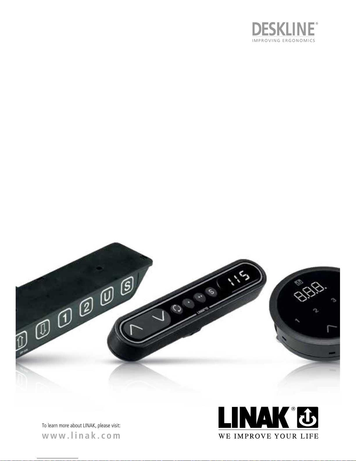
Page 1 of 44
To learn more about LINAK, please visit:
www.linak.com
USER MANUAL
Controls/Handsets
Page 2

Page 2 of 44
Page 3

Page 3 of 44
Contents
Preface..................................................................................................................................................4
Safety instructions .............................................................................................................................. 5
Repairs ..................................................................................................................................................7
Manufacturer’s declaration................................................................................................................7
Misc. on the DESKLINE
®
system ........................................................................................................ 8
Warranty..........................................................................................................................................8
Maintenance....................................................................................................................................8
ETL-marking ......................................................................................................................................... 8
Overview of the DESKLINE Controls product range .................................................................... 10
Mounting guidelines for DPA/DPB ................................................................................................. 11
Mounting guidelines for DPH ......................................................................................................... 11
Operation of the DP1........................................................................................................................11
Operation of the simple desk panels .............................................................................................12
Operation of the DP1C ..................................................................................................................... 13
Operation of the DP1CS ................................................................................................................... 15
Remote control HB10RF / HB20IR ................................................................................................... 17
Activating the learning mode .........................................................................................................18
Operation of the DPF ........................................................................................................................ 19
K-version ....................................................................................................................................... 19
2K- and 3K-version ........................................................................................................................ 19
M-version ...................................................................................................................................... 19
Operation of the DPF1C “one reference” ...................................................................................... 20
Operation of the DPF1D ................................................................................................................... 21
Operation of the DPF4T “multiple references” .............................................................................22
Other functions common for DPF1C and DPF4T .............................................................................. 23
Mounting of all DPF versions ..........................................................................................................24
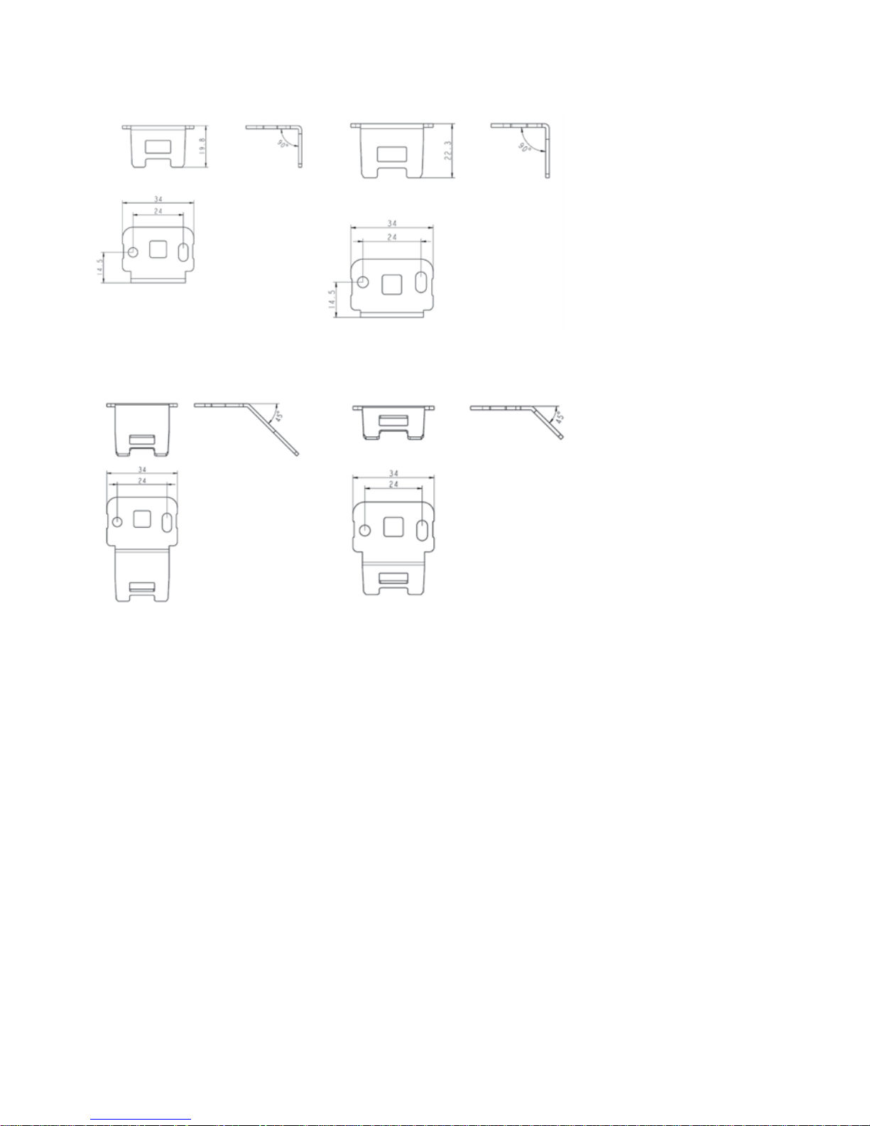
Drawings of the mounting brackets ................................................................................................25
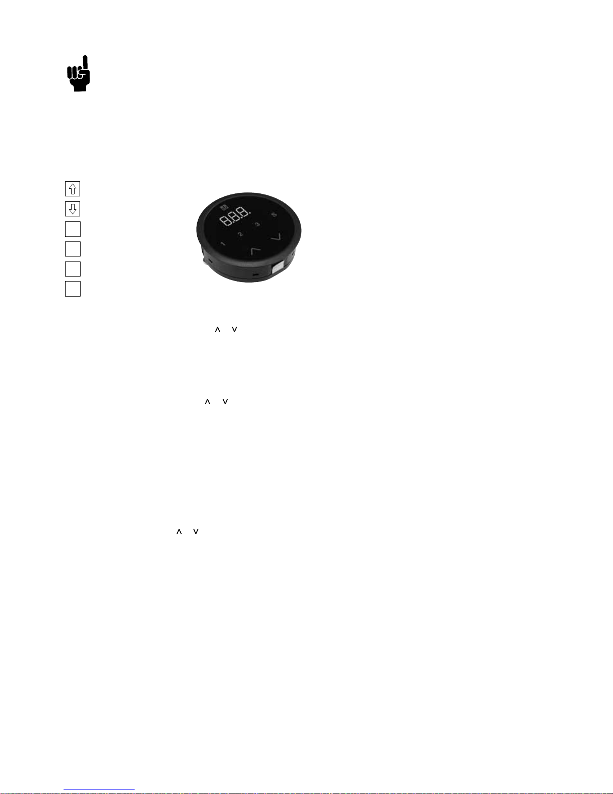
Operation of the DPT ........................................................................................................................26
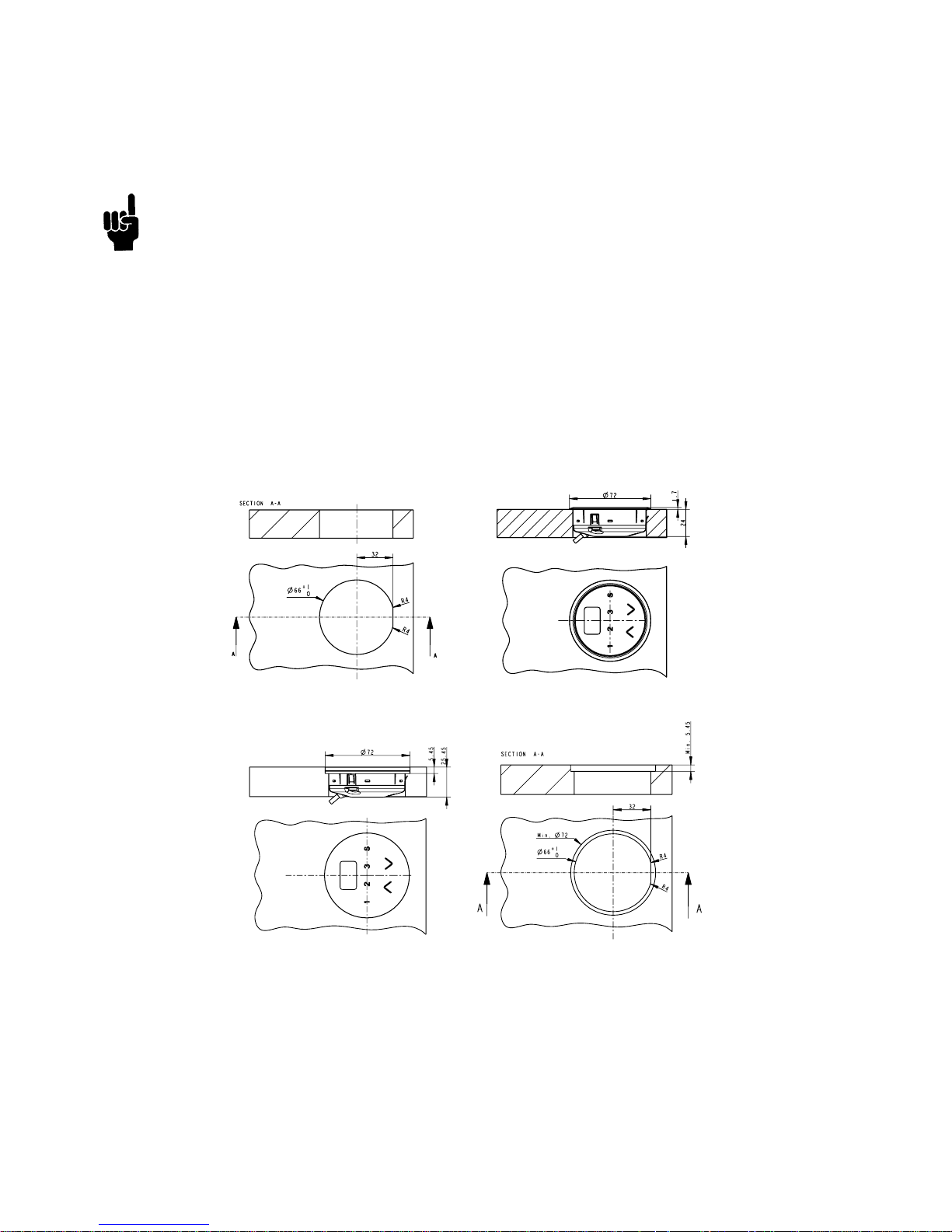
Mounting of the DPT ........................................................................................................................ 28
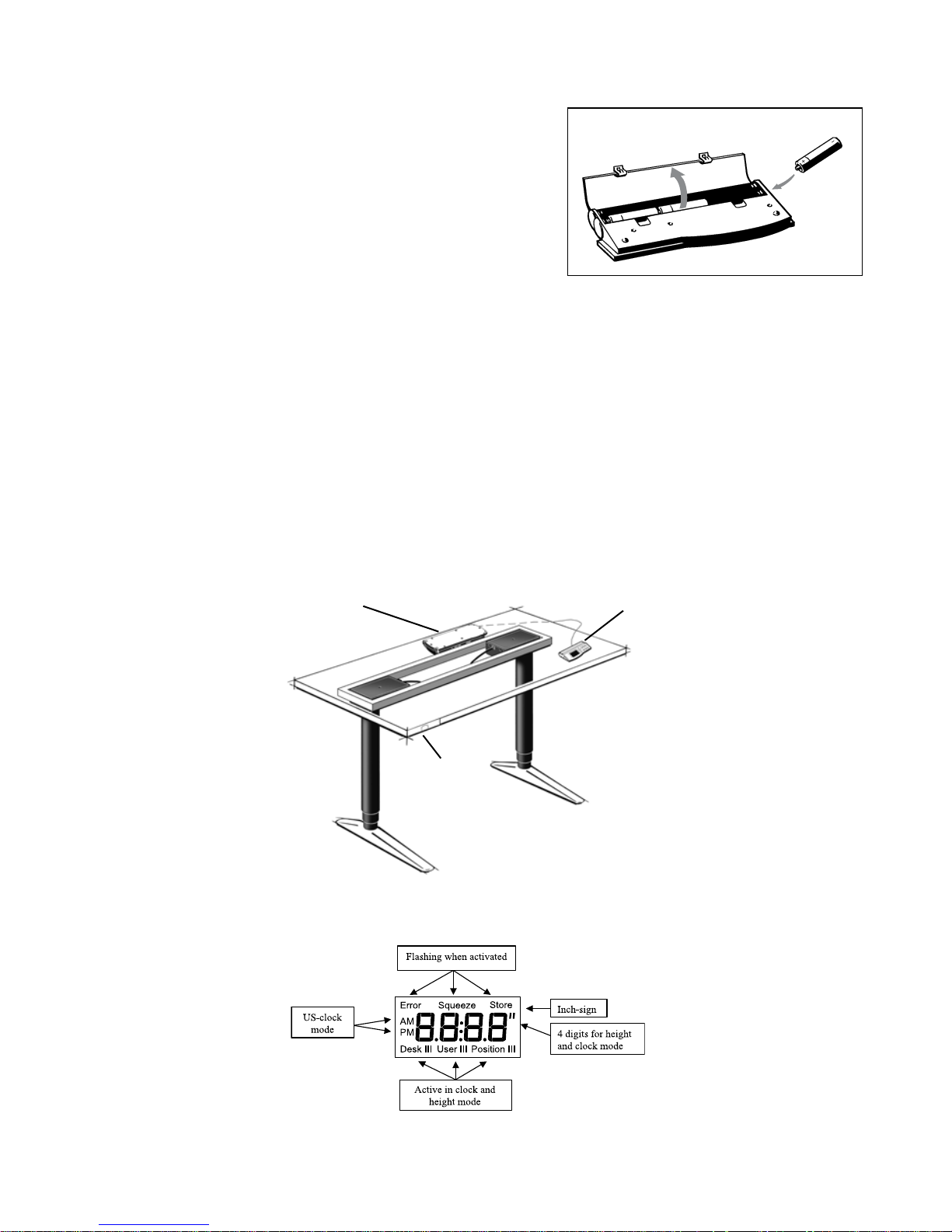
Operation of the WDPL .....................................................................................................................29
Calibrating the WDPL ..................................................................................................................... 30
Adjusting the clock ........................................................................................................................ 31
Troubleshooting ............................................................................................................................. 31
Store a memory position ................................................................................................................ 32
Switch to a stored memory position ................................................................................................ 33
Disposal of LINAK’s products .........................................................................................................34
Disposal of batteries ........................................................................................................................34
Labels ................................................................................................................................................35
Drawing appendix ............................................................................................................................. 36
Addresses ........................................................................................................................................... 44
Page 4

Page 4 of 44
Preface
Dear User,
We are delighted that you have chosen a product from LINAK
®
.
LINAK systems are high-tech products based on many years of experience in the manufacture and development of
actuators, electric control boxes, controls and chargers.
This User Manual does not address the end-user. It is intended as a source of information for the manufacturer
of the equipment or system only, and it will tell you how to install, use and maintain your LINAK electronics. It
is the responsibility of the manufacturer of the end-use product to provide a User Manual where relevant safety
information from this manual is passed on to the end-user.
We are sure that your LINAK product will give you many years of problem-free operation.
Before our products leave the factory they undergo full function and quality testing. Should you nevertheless
experience problems with your systems, you are always welcome to contact your local dealer.
LINAK subsidiaries and some distributors situated all over the world have authorised service centres, which are
always ready to help you.
LINAK provides a warranty on all its products. This warranty, however, is subject to correct use in accordance with
the specifications, maintenance being done correctly and any repairs being carried out at a service centre, which is
authorised to repair LINAK products.
Changes in installation and use of LINAK systems can affect their operation and durability. The products are not to
be opened by unauthorised personnel.
The User Manual has been written based on of our present technical knowledge. We are constantly working on
updating the information and we therefore reserve the right to carry out technical modifications.
LINAK A/S
Page 5
Page 5 of 44
Safety instruction
General
Important information
Important information on LINAK
®
products can be found under the following
headings:
Warning!
Failure to comply with these instructions may result in accidents involving
serious personal injury.
Failing to follow these instructions can result in the product being damaged
or being destroyed.
Safe use of the system is possible only when the operating instructions are read
completely and the instructions contained are strictly observed.
Failure to comply with instructions marked with the ”NOTE” symbol may result in
serious damage to the system or one of its components.
It is important for everyone who is to connect, install, or use the systems to
have the necessary information and access to this User Manual. Follow the
instructions for mounting – risk of injury if these instructions are not followed.
The appliance is not intended for use by young children or infirm persons
without supervision.
If there is visible damage on the product it must not be installed.
Note that during construction of applications, in which the actuator is to
be fitted, there must be no possibility of personal injury, for example the
squeezing of fingers or arms.
Assure free space for movement of application in both directions to avoid
blockade.
Page 6
Page 6 of 44
Only for EU markets
This appliance can be used by children aged from 8 years and above and
persons with reduced physical, sensory or mental capabilities or lack of
experience and knowledge if they have given supervision or instruction
concerning use of the appliance in a safe way and understand the hazards
involved.
Children shall not play with the appliance. Cleaning and user maintenance
shall not be made by children without supervision.
Only for Non EU markets
Persons who do not have the necessary experience or knowledge of the
product/products must not use the product/products. Besides, persons with
reduced physical, sensory or mental abilities must not use the product/products,
unless they are under surveillance or they have been thoroughly instructed in
the use of the apparatus by a person who is responsible for the safety of these
persons.
Moreover, children must be under surveillance to ensure that they do not
play with the product.
Misuse
Do not overload the actuators – this can cause danger of personal injury and
damage to the system.
Do not use the actuator system for lifting persons. Do not sit or stand on a
table while operating – risk of personal injury.
Do not use the system in environments other than the intended indoor use
Page 7
Page 7 of 44
Repairs
In order to avoid the risk of malfunction, all DESKLINE® repairs must only be carried out by authorised LINAK® workshops or
repairers, as special tools must be used and special gaskets must be fitted. Lifting units under warranty must also be returned
to authorised LINAK workshops.
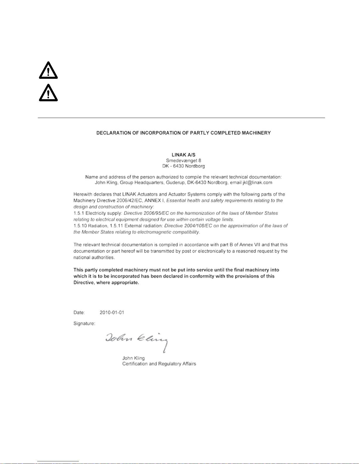
Warning!
If any of the DESKLINE
®
products are opened, there will be a risk of subsequent malfunction.
Warning!
The DESKLINE® systems are not resistant to cutting oil.
Page 8

Page 8 of 44
Misc. on the DESKLINE® system
Warranty - 60 months on DESKLINE® (NEW)
This will be valid for all DESKLINE
®
products produced after the 1st of May 2015.
Products produced before 1
st
of May 2015 will still be covered by 36 months.
Products used in DESKLINE application: If these products are used in another application, they will be covered by 18 months
warranty.
If there is any doubt that returned products are within the warranty period it is to be treated as if they are covered by the
warranty. We recommend that you use the date of the Control box or actuator as reference if possible. We will have our
purchase no. printed on the label.
Maintenance
Clean dust and dirt on the outside of the system at appropriate intervals and inspect for damage and breaks.
Inspect the connections, cables, and plugs and check for correct functioning as well as fixing points.
The cleaners and disinfectants must not be highly alkaline or acidic (pH value 6-8).
ETL-marking
Due to space limitations, the complete ETL-marking demands are not represented on the marking plates.
The full ETL Recognized Component markings are shown here.
C/N 120690
Conforms to ANSI/AAMI Std. ES60601-1
Cert. to CSA Std. C22.2 No. 60601-1
ETL Recognized Component mark for Canada and United States
C/N 4008003
Conforms to ANSI/AAMI Std. ES60601-1
Cert. to CSA Std. C22.2 No. 60601-1
ETL Recognized Component mark for Canada and United States
C/N 4008004
Conforms to ANSI/AAMI Std. ES60601-1
Cert. to CSA Std. C22.2 No. 60601-1
ETL Recognized Component mark for Canada and United States
C/N 4008005
Conforms to ANSI/AAMI Std. ES60601-1
Cert. to CSA Std. C22.2 No. 60601-1
ETL Recognized Component mark for Canada and United States
C/N 4008623
Conforms to ANSI/AAMI Std. ES60601-1
Cert. to CSA Std. C22.2 No. 60601-1
ETL Recognized Component mark for Canada and United States
Page 9

Page 9 of 44
C/N 4008671
Conforms to UL962
Cert. to CSA Std. C22.2 No. 68-09
ETL Recognized Component mark for Canada and United States
C/N 4008838
Conforms to ANSI/AAMI Std. ES60601-1
Cert. to CSA Std. C22.2 No. 60601-1
ETL Recognized Component mark for Canada and United States
C/N 4009507
Conforms to UL962
Cert. to CSA Std. C22.2 No. 68-09
ETL Recognized Component mark for Canada and United States
C/N 9901916
Conforms to ANSI/AAMI Std. ES60601-1
Cert. to CSA Std. C22.2 No. 60601-1
ETL Recognized Component mark for Canada and United States
Page 10
Page 10 of 44
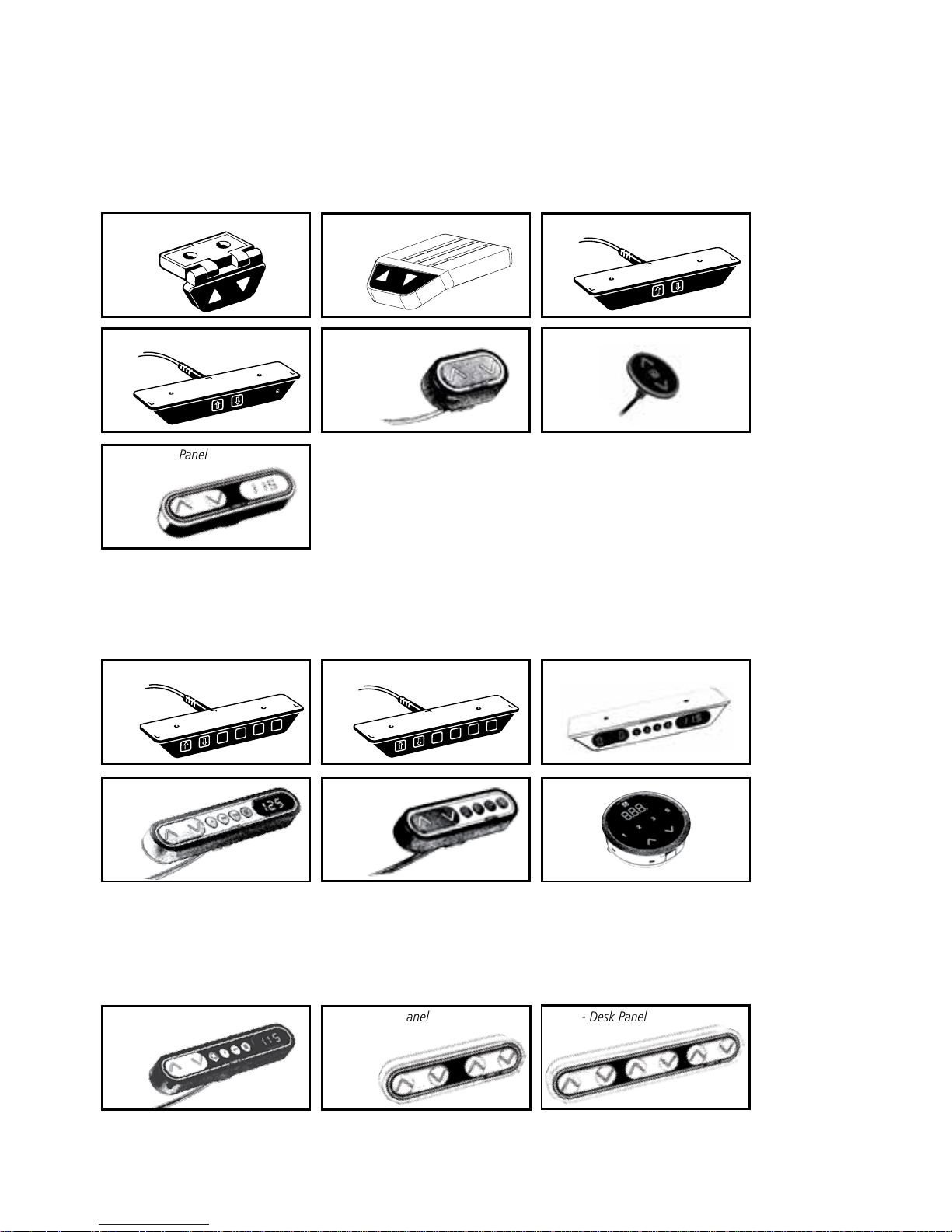
Overview of the DESKLINE Controls product range
The desk panel is used to operate the DESKLINE system. The desk panel product range consists of number of desk panels with
different functions:
For single/parallel drive without memory: DPA, DPB, DP1K, DP1V, DPF1K, DPH and DPF1D
For drive of more references: DPF4T, DPF2K and DPF3K
DPF2K - Desk Panel
DPF3K - Desk Panel
DPF4T - Desk Panel
For single/parallel drive with memory: DP1N, DP1U, DP1CS, DPF1C, DPF1M and DPT
DP1U - Desk Panel
2
1
3
S
2
1
U
S
DP1N - Desk Panel
DP1CS - Desk Panel
DPF1M - Desk Panel
DPF1C - Desk Panel
DPT
DPA - Desk Panel
DP1K - Desk Panel
DPB - Desk Panel
DP1V - Desk Panel
DP-025
DPH - Desk PanelDPF1K - Desk Panel
DPF1D - Desk Panel
Page 11
Page 11 of 44
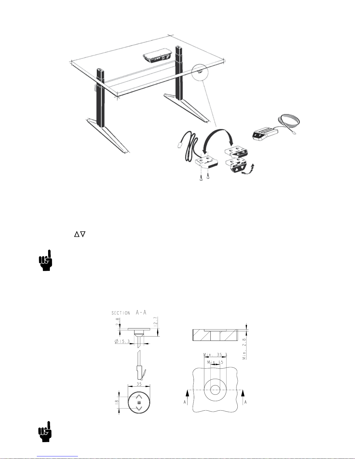
Mounting guidelines for DPA/DPB
The DPA/DPB can be mounted on the desktop so that the keys are either facing upwards or outwards. Alternatively the DPA
can be mounted flat under the desktop with the keys facing downwards.
Operation of the DPA/DPB in connection with DESKLINE® systems (not CBD2N)
The Desk Panel is used to operate the DESKLINE system. The two arrow buttons are used for parallel drive.
Parallel drive ( )
The arrow buttons start parallel drive. The function is only activated when holding the button down.
The mounting screws on the DP, DPA, or DPB must be fastened with a max. torque of 1 Nm.
Mounting guidelines for DPH
The hole in the tabletop must be in accordance with this drawing.
Page 12
Page 12 of 44
Desk up
Desk down
Store memory
User memory
Memory 1
Memory 2
Memory 3
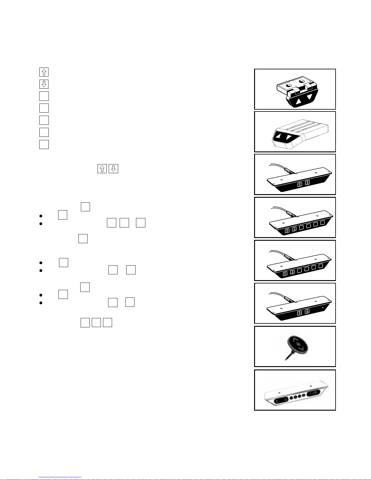
Operation of the simple desk panels
Here you find the guide on how to operate the DPA, DPB, DP1K, DP1N, DP1U, DP1V, DPH and DP1CS
Single/parallel drive
The arrow buttons start the DESKLINE lifting column.
The function is only activated when holding down the button.
S
U
1
2
3
DP1U - Desk Panel
2
1
3
S
DPA - Desk Panel
DP1K - Desk Panel
DPB - Desk Panel
DP1V - Desk Panel
DP-025
2
1
U
S
DP1N - Desk Panel
DPH - Desk Panel
Store memory
Push
Within two sec. push either , or
1
2
3
S
S
Choice of user (only DP1N)
Two persons can store 2 memory positions each.
Select user 1 or user 2.
Push
Within two sec. push either or
Store memory
Push
Within two sec. push either or
S
U
U
1 2
S
1
2
Memory drive
Memory 1, 2, and 3 start a memory drive, the channel(s)
drive to a preprogrammed position.
1 2 3
DP1CS - Desk Panel
Page 13
Page 13 of 44
Description
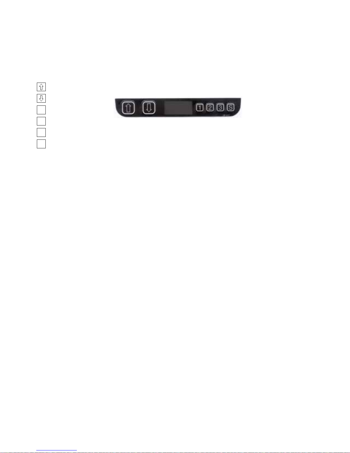
The DP1C is equipped with display and memory and is compatible with CBD4 (Advanced, software 077402 ver. 1.66 or later).
The DP1 is only available as a 1-channel version for operation of the parallel channels up and down. The actual height of the
desk is shown in the display. The display is of the LED type with a yellow light and 10 mm high digits.
Normal operation:
To run the desk up or down, press the UP or DOWN button, and keep it pressed until the desk reaches the desired height. The
display will count up or down while running, and after stop it will continually show the current height of the desk.
Changing between cm and inches:
Keep the S button pressed for approx. 4 sec. and the reading will change from the current setting.
The default setting depends on the type chosen.
Store a memory position:
When pressing the “store” button, the display will flash “S” for 3 sec. Within the 3 sec. press memory button 1, 2 or 3. The
display will acknowledge by showing S1, S2 or S3 for 1 sec. To abort a store sequence, press the UP or DOWN button while
the “S” is flashing, or wait the 3 sec. until the display automatically returns to show the height of the desk.
Drive to a stored position:
Version with “GO-memory”
Press memory button 1, 2, or 3. The display will flash “GO1”, “GO2” or “GO3” for 3 sec. Within the 3 sec. press the UP or
DOWN button and keep it pressed until the desk stops in the stored position. Both the Up and the Down button will activate
memory drive. Although e.g. the memory position is higher than the actual height, it will drive upwards when you press the
Down button. While running to a memory position the display will show GO1, GO2 or GO3, and when it stops in the stored
position, the height of the desk will be shown. Releasing the UP or DOWN button will abort the memory drive. The display will
show the height of the desk.
Version with “standard memory”
Press memory button 1, 2, or 3 and the system will start driving to the wanted memory position. Keep the button pressed until
the position is reached. The display will show the actual height during the memory run.
Adjust the display to show the correct height:
It may be necessary to adjust the display due to different thicknesses of desktops etc, when the DP is delivered from the
factory. The DP will show 68 cm or 24.5 inches (default setting) height of the desk. At the same time press the “Store” button
and step UP or DOWN, until the display shows the correct height.
Adjusting the light intensity of the LED display
Possible light settings are: 0 = off, 25 = 25%, 50 = 50%, 75 = 75%, 100 = 100%.
Adjustment procedure
Press the “1” button and at the same time either “desk up” or “desk down” this will adjust the light intensity. Initial press will
show the current setting. Keep the “1” button pressed during the whole sequence while adjusting up or down. Keep a button
pressed for more than 800 msec then the button will auto repeat every 100 msec. Releasing all buttons stores the new setting.
Adjusting the light timeout
Possible light timeouts are: 0-15 sec and off
Adjustment procedure
Press the “3” button and at the same time either “desk up” or “desk down” - this will adjust the light timeout. Initial press
Operation of the DP1C
The DP1C cannot be used on the CBD4 with mains cut-off.
Desk up
Desk down
Store memory
Memory 1
Memory 2
Memory 3
S
1
2
3
Page 14

Page 14 of 44
Error no. Description
E01 The desk has an unknown position and needs to be initialised.
E02 Overload upwards has occurred.
E03 Overload downwards has occurred.
E16 Illegal keys pressed.
will show the current setting. Keep the “3” button pressed during the whole sequence while adjusting up or down. Keep a
button pressed for more than 800 msec, then the button will auto repeat every 100 msec. Releasing all buttons stores the new
setting.
Errors
Below please find the possible errors that can be displayed. The errors will only be displayed when a button is pressed. The
display blinks while showing the error. E16 overrules any other error as the detection is registered only in the display and no
message is sent to the control box.
Diagnostic errors
The CBD4 (version 1.86 or later) can send up to 6 different diagnostic error codes at the same time.
The diagnostic error codes will overrule error states (except E16). Diagnostic errors will only appear as long as the button is
pressed. The display will blink EXX and will toggle through the diagnostic errors and send them to the LINBUS in the CBD. For
detailed error description and codes, please see the appropriate CBD software description.
(Only working with DP1C from production date 1 february 2006 and onwards)
Page 15
Page 15 of 44
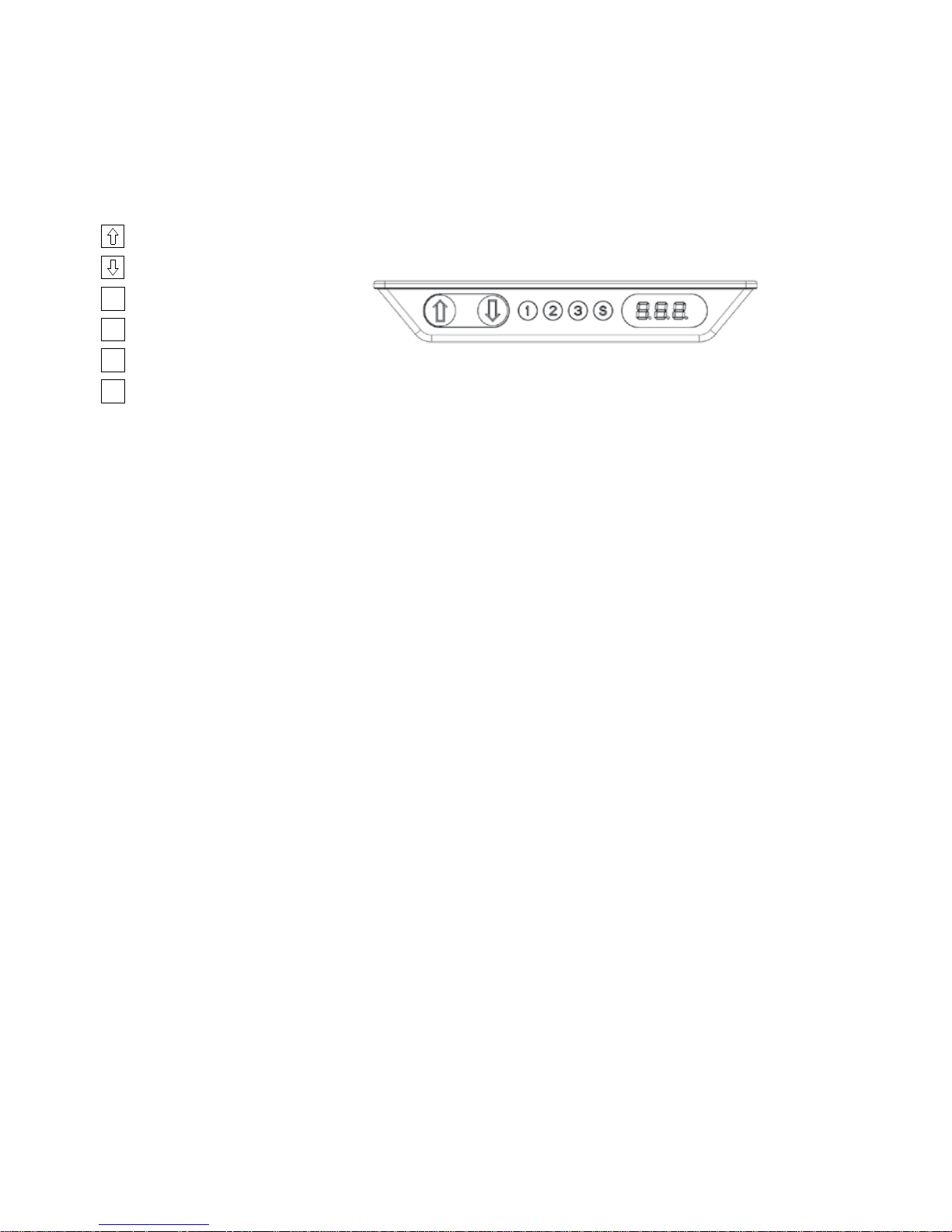
Description
The DP1CS is equipped with display and memory and is compatible with DESKLINE control boxes. The DP1CS is available as a
1-channel version for operation of the parallel channels up and down. The actual height of the desk is shown in the display.
The display is of the LED type with a yellow light and 10 mm high digits.
Up and down (
^
V):
You just either have to activate the up or down button for parallel drive and the system will drive until releasing the button
again or when the system reaches end position.
Memory:
The four small buttons are used for memory drive/storing memory.
Store memory
• Press S – button, the display will flash “S” for 2 seconds
• Within these two seconds press one of the small buttons with numbers “1”, “2” or “3” and the position
will be stored at this button.
• The panel will acknowledge by showing “1”, “2” or “3” in the display depending on the chosen position
Memory drive
Press one of the memory buttons and the system will start driving to the pre-programmed memory position. Keep the button
pressed until the position is reached.
Display function
Shows the actual height in either cm or inch and can display error codes.
Operation of the DP1CS
Parallel up
Parallel down
Memory 1
Memory 2
Memory 3
Store memory
S
1
2
3
Page 16

Page 16 of 44
Error no. Description
E01 The desk has an unknown position and needs to be initialised.
E02 Overload in upward direction has occurred.
E03 Overload in downward direction has occurred
E16 Illegal keys are pressed.
Other functions:
Adjusting initial height:
It may be necessary to adjust the displayed height due to different thicknesses of desktops etc. The DP1CS will as standard
show either 68cm or 24.5 inch as the default desk height.
Procedure:
Press /\ and \/ keys at the same time and keep them pressed for 5 seconds. This allows the initial height to be adjusted. Until
the initial height can be adjusted, the display will show three minuses (---) - hereafter the display will revert to showing the
height. The height can then be adjusted by either /\ or \/ until the desired height has been reached. The system will return to
normal operation (and give a short blink) after 5 seconds of inactivity on the keys.
The feature can be disabled via configuration in which case pressing the /\ and \/ keys at the same time will be considered an
illegal keypress.
Switch between cm and inch:
Switching between cm and inch can only be done via the DPF configurator
Adjusting the light intensity of the LED display:
Possible settings are Off, 6%, 12%, 19%, 25%, 37%, 50%, 75% and 100%.
The adjustment can only be done via the DPF configurator.
Adjusting the light timeout:
Possible settings are 0-15 seconds and Off.
The adjustment can only be done via the DPF configurator.
Error codes
Below please find the possible error codes that can be displayed. The error codes will only be displayed when a button is
pressed. The display will blink while showing the error code. The E16 error will overrule any other errors as the detection is
registered only in the display and no message is send to the control box.
Page 17
Page 17 of 44
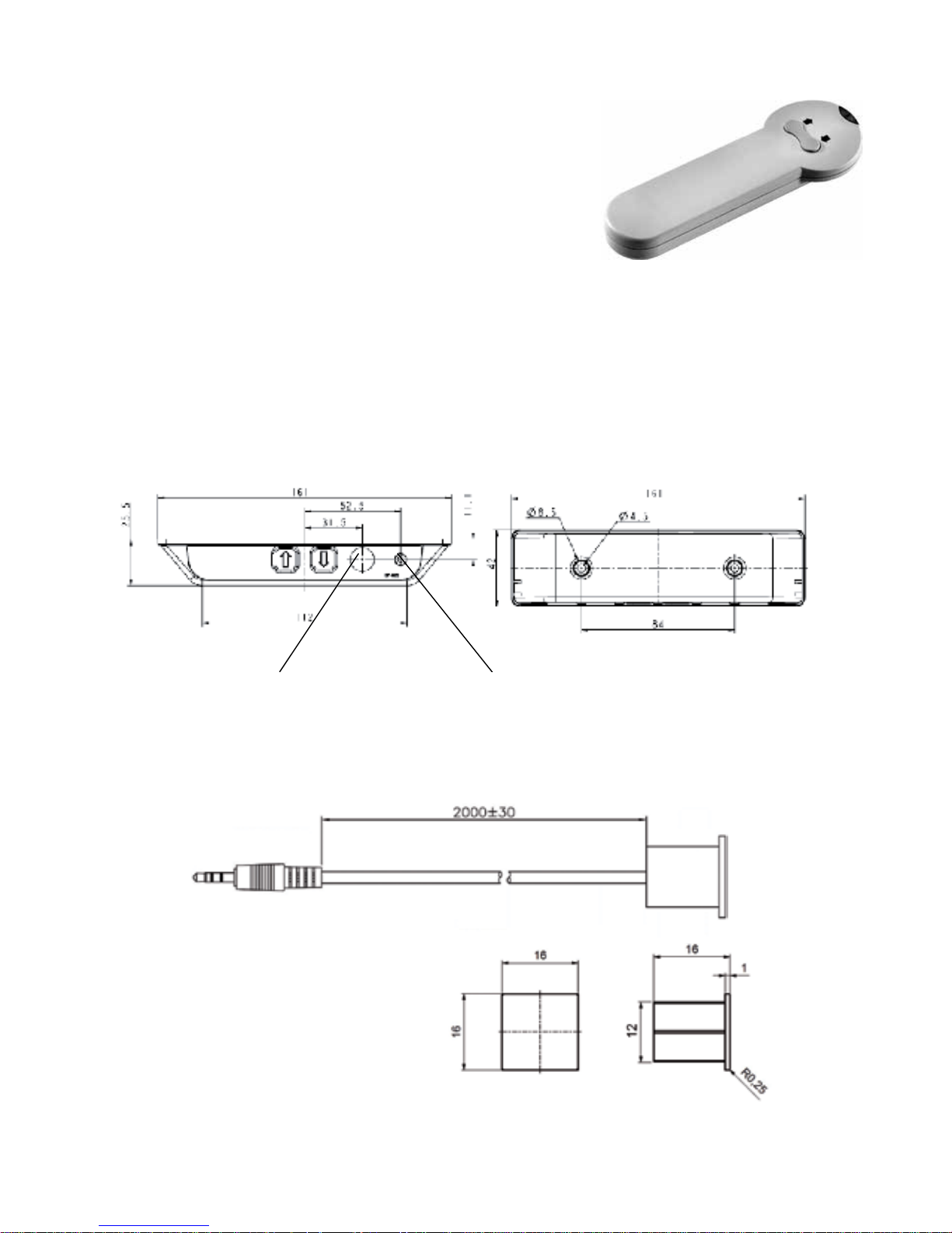
Position of the internal eye
Connector for extension eye
Remote control HB10RF / HB20IR
Operation of the system:
The HB21 IR transmitter is a simple up/down control with a button for the up
activation and a button for the down activation of 1 reference on the CBD.
The HB22 is a two-channel controller, for controlling two references on the CBD.
For activation of the control box point with the HB20 at the DP1V or the extension eye: Press the button up or down.
The operation range for the HB20 is approx. 6 m.
Drawings:
DP1V
IR extension eye article number 0964571
The IR extension eye is for mounting in a 12 mm hole. The eye has a 2000 mm cable with a mini Jack plug, which is to be
plugged into the DP1V.
Page 18
Page 18 of 44
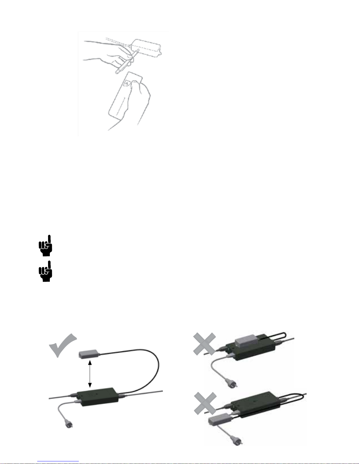
Activating the learning mode:
Activate the reset key on the RFR by using a pen or similar to keep the button pressed.
• Keeping the reset key activated; the RF handset must be activated by pressing a random key on the RF handset.
The RF handset IDs are stored in the memory and at the same time, previous RF handset IDs are erased.
• After having activated the RF handset keys the reset key must be released.
• If no RF handset keys are activated during the matching procedure; no changes are made in the ID memory.
• Please be aware that other equipments (as e.g. doorbells), which use the 433 MHz can disturb the RF signal.
Every RF handset has its own 32 bit unique address and the RF protocol contains a check sum which ensures that only
the handset that has been activated during the learning process can activate the system. No noise signal from other RF
equipment can activate the system, but might prevent it from running depending on the signal strength of the noise signal.
The operation range for the HB10 is approx. 6 m, but depending on the surroundings where it is mounted it can be less. E.g.
if the receiver is mounted in a cabinet along with other equipment.
To avoid signals getting disturbed, do not use more than two RFRL boxes in one room.
The RF uses the frequency 433 MHz
How to place the RFRL box
The RFRL box must be mounted minimum 30 cm from the CBD and conductive mains cables.
Correct placement Wrong placements
Min. 30 cm
Page 19
Page 19 of 44
Operation of the DPF
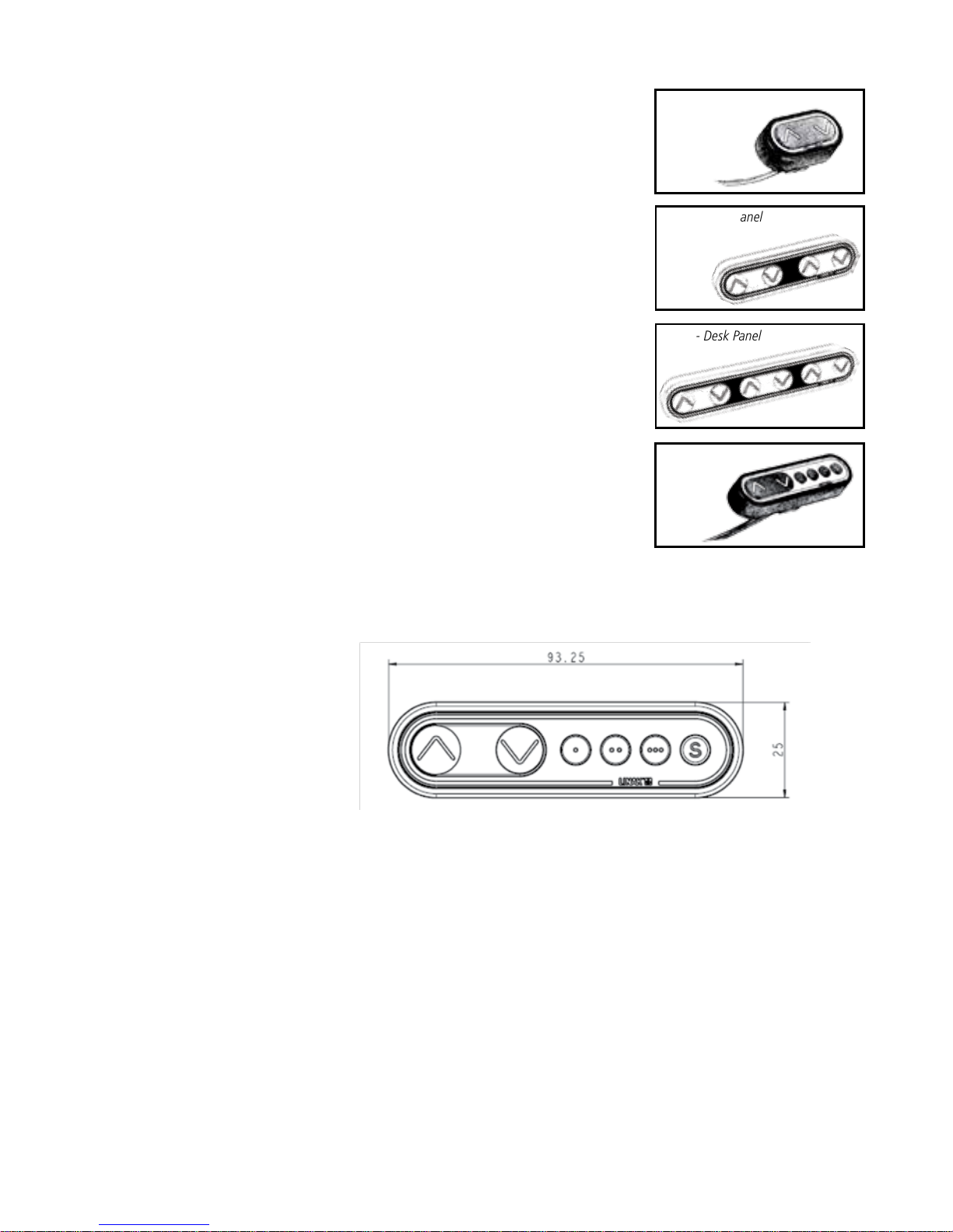
= Parallel up
V = Parallel down
S = Store memory
• = Memory 1
•• = Memory 2
••• = Memory 3
Parallel drive ( V)
The arrow buttons start parallel drive. The function is only activated when holding the button down.
Store memory
• Press S – button
• Within two seconds press one of the small buttons with dots and the position will be stored at this button.
Memory drive (small buttons with dots)
Press one of the memory buttons and the system will start driving to the pre-programed memory position.
Keep the button pressed until the position is reached.
DPF1K - Desk Panel
DPF1M - Desk Panel
K-version:
Just activate either the up or down button for parallel drive and the system will
drive until the button is released again or the system reaches end position.
2K-version:
Just activate either the up or down button and the system will drive until the
button is released again or the system reaches end position. Each set of up/down
buttons refers to a reference. You can only drive one reference at a time. The desk
panel can have up to 2 references.
3K-version:
Just activate either the up or down button and the system will drive until the
button is released again or the system reaches end position. Each set of up/down
buttons refers to a reference. You can only drive one reference at a time. The desk
panel can have up to 3 references.
M-version:
The DPF is divided into parallel and memory drive. The two arrow buttons are
used for parallel drive and the last four buttons for memory drive/storing memory.
V
V
DPF2K - Desk Panel
DPF3K - Desk Panel
Page 20
Page 20 of 44
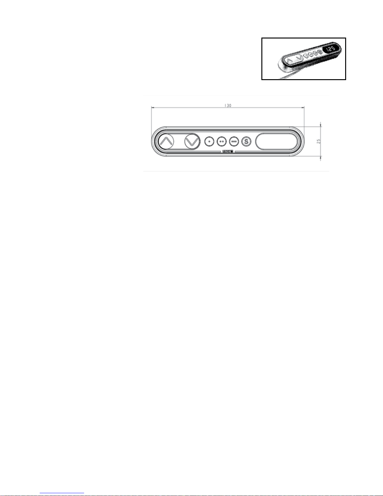
DPF1C - Desk Panel
Operation of the DPF1C “one reference”
Up and down (
V):
Just activate either the up or down button for parallel drive and the system will drive until the button is released again or the
system reaches end position.
Memory:
The four small buttons are used for memory drive/storing memory.
Store memory
• Press S – button, the display will flash for 2 seconds
• Within these two seconds press one of the small buttons with dots and the position will be stored at this button.
• The panel will acknowledge by showing “1”, “2” or “3” in the display depending on chosen position
Memory drive (small buttons with dots)
Press one of the memory buttons and the system will start driving to the pre-programmed memory position.
Keep the button pressed until the position is reached.
Display function
Shows the actual height in either cm or inch.
= Parallel up
V = Parallel down
S = Store memory
• = Memory 1
•• = Memory 2
••• = Memory 3
V
V
Page 21
Page 21 of 44
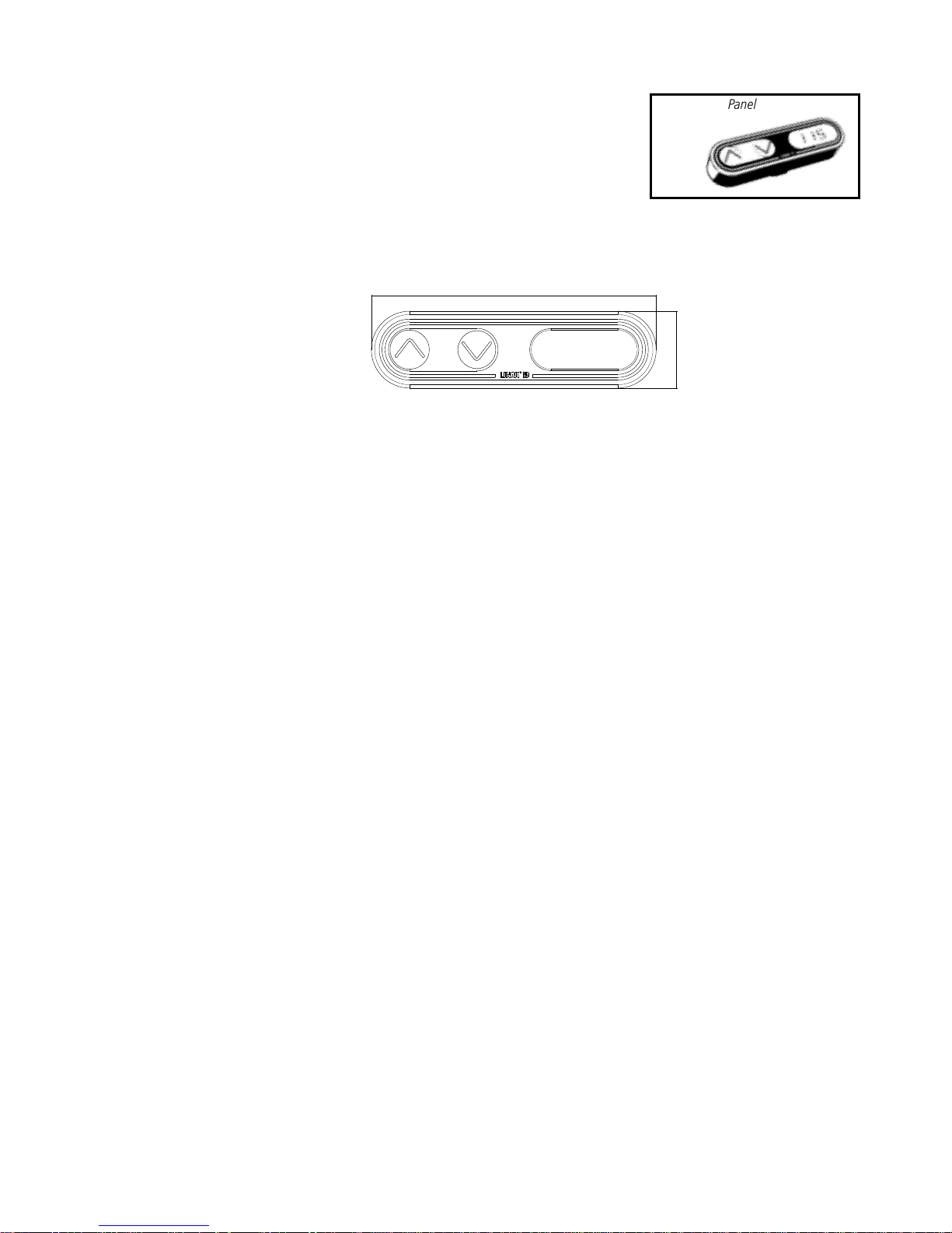
Operation of the DPF1D (Display and up/down drive)
Function:
Compared to a standard DPF1C the DPF1D has no memory positions. The panel is a simple one that will show the height when
adjusting and error codes when needed.
Up and down (^V):
You just either have to activate the up or down button for parallel drive and the system will drive until releasing the button
again or when the system reaches end position.
Display function:
Shows the actual height in either cm or inch and can display error codes
= Parallel up
V = Parallel down
V
93.5
18.5
25.5
DPF1D - Desk Panel
Page 22
Page 22 of 44
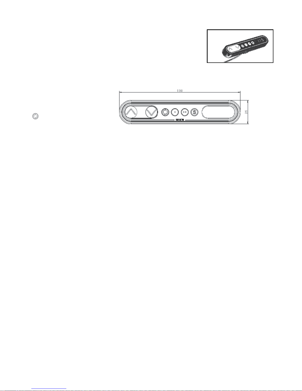
DPF4T - Desk Panel
Operation of the DPF4T “multiple references”
Function:
Compared to a standard DPF1C the first memory button on the DPF4T is replaced by a toggle button, i.e. that the panel has 2
memory buttons instead of 3 (memory 1 and memory 2).Besides the toggle button the DPF4T works like the DPF1C.
Up and down (
V):
You just either have to activate the up or down button for parallel drive and the system will drive until releasing the button
again or when the system reaches end position.
Memory:
The four small buttons are used for toggle function, memory drive and storing memory.
Store memory
• Press S – button, the display will flash for 2 seconds
• Within these two seconds press one of the small buttons with dots and the position will be stored at this
button 1A.
• The panel will acknowledge by showing “1”or “2” in the display depending on the chosen position
Memory drive (small buttons with dots)
Press one of the memory buttons and the system will start driving to the pre-programmed memory position.
Keep the button pressed until the position is reached.
Display function
Shows the actual height in either cm or inch.
= Parallel up
V = Parallel down
S = Store memory
= Toggle button
•• = Memory 1
•• = Memory 2
V
V
Page 23

Page 23 of 44
Toggle function (Operation):
Press the “Toggle” button to toggle through all reference choices and make a selection to which reference you would like
to use. For example, the display may show 123 – press one more time and 234 is shown*. Since 3 is the bolded number, you
have now selected reference 3 and the up down buttons are running reference 3 up-down.
When activating the up down button it first displays the reference number shortly for ½ sec then the actual height.
Reference setup is set in the CBD4 using the configuration software.
The DPF will automatically find out how the system is configured; One, two, three or four references.
* If only two references exist 121 // 212 is shown in the display.
Important notes:
All actuator ports must be used.
If you create a 2 reference system (2 parallel + singles) and only use three ports on a 4-channel control box, the desk panel
will show “123”. You will be able to select reference three even through it is not connected.
The multi controller must not be used in combination with CBD4 software with the impulse drive feature. There is a risk that
the used software initiate impulse movement, toggle to the next reference and therefore cannot stop the movement until it is
back at the reference with impulse.
Memory positions:
1A The memory position will be for all references. When using memory one or two, reference one will first drive to its memory
position followed by reference two and so on.
Other functions common for DPF1C and DPF4T
Adjusting initial height
It may be necessary to adjust the displayed height due to different thicknesses of desktops etc. The DPF1C will as standard
either show 68 cm or 24.5 inch as the default desk height.
Procedure:
Press /\ and \/ keys at the same time and keep them pressed for 5 seconds. This allows the initial height to be adjusted. Until
the initial height can be adjusted, the display will show three minuses (---) hereafter the display will revert to showing the
height. The height can then be adjusted by either /\ or \/ until til desired height has been reached. The system will return to
normal operation (and give a short blink) after 5 seconds of inactivity on the keys.
The feature can be disabled via configuration in which case pressing the /\ and \/ keys at the same time will be considered an
illegal keypress.
Switch between cm and inch.
Switching between cm and inch can only be done via the DPF1C configurator.
Adjusting the light intensity of the LED display
Possible settings are Off, 6%, 12%, 19%, 25%, 37%, 50%, 75% and 100%.
The adjustment can only be done via the DPF1C configurator.
Adjusting the light timeout
Possible settings are 0-15 seconds and Off.
The adjustment can only be done via the DPF1C configurator.
Page 24
Page 24 of 44
Error codes
Below please find the possible error codes, which can be displayed. The error codes will only be displayed when a button is
pressed. The display will blink while showing the error code. The E16 error will overrule any other errors as the detection is
registered only in the display and no message is send to the control box.
Error code Description
E01 The desk has a unknown position and needs to be initialised.
E02 Overload in upwards direction has occurred.
E03 Overload in downwards direction has occurred.
E16 Illegal keys are pressed
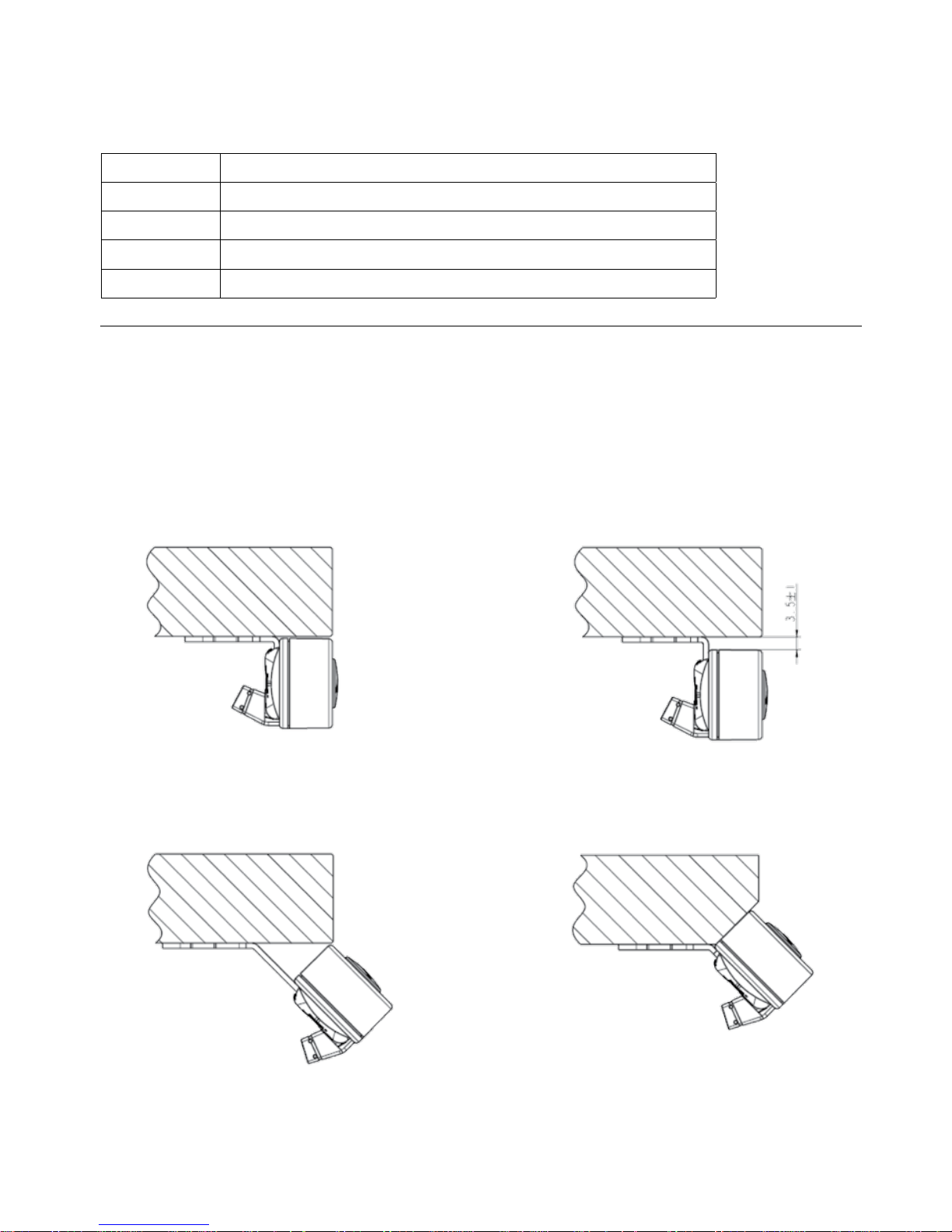
Mounting of all DPF versions
The DPF must be mounted via a mounting bracket. The mounting bracket comes in 4 different versions depending on how the
panel should be mounted. Below are some examples on ways to mount:
To mount the panel:
Just click the panel into the bracket and it is fixed.
Example 1: (Article number 914759)
The panel is mounted with a 90° bracket and
placed close to the tabletop
Example 2: (Article number: 914757)
The panel is mounted with a 90° bracket and
place with a distance to the tabletop
Example 3: (Article number 914760)
The panel is mounted with a 45° bracket and
placed at the edge of the tabletop
Example 4: (Article number 914785)
The panel is mounted with a 45° bracket and
placed on a tabletop with angled front
Page 25
Page 25 of 44
Drawings of the mounting brackets:
Article number 914759 Article number 914757
Article number 914760 Article number 914785
Page 26
Page 26 of 44
For safety reasons the DPT has a locking function.
If the DPT is locked, only a bar is lightning in the display. To unlock the control press ¨S¨ for 1 sec. When the DPT is
unlocked, the height will be shown in the display. Now the DPT is active for 2.5 seconds. When pressing one of the
keys you can do your adjustment. Hereafter the DPT will be active for 5 seconds but when there are no activations
made within the mentioned time slot, the DPT will go in to locking mode again. Also, if you press ¨S¨ for unlocking too
long, the DPT will unlock but immediately lock again.
The Touch Desk Panel is used to operate the DESKLINE® systems. The DPT is divided into parallel and memory drive. The two
arrow buttons are used for parallel drive and the last four buttons for memory drive.
Normal operation:
To run the desk up or down, press the or button, and keep it pressed until the desk reaches the desired height.
The display will count the height as the table is moving and will continually show the height of the desk after stopping.
Storing a memory position:
Touch the “S” button and the display will flash “S” for 3 sec. While the ¨S¨ is displayed, touch the memory button 1, 2 or 3.
The display will acknowledge by showing S1, S2 or S3 for 1 sec.
To abort a store sequence press the or button while the “S” is flashing, or wait the 3 seconds until the display
automatically returns to show the height of the desk.
Drive to a stored position:
Press memory button 1, 2 or 3 and the system will start driving to the desired memory position. Keep the button activated until
the position is reached. The display will count the height as it is driving to the memory position.
Customising the DPT digital display
Adjust the display to show the correct height:
The DPT will show 68 cm or 24.5 inches as the height of the desk as the default setting. It may be necessary to adjust the
displayed height due to different thicknesses of desktops etc. when the DPT is delivered from the factory. To adjust the display
touch the ¨S¨ button and the or button at the same time until the display shows the actual height of the desk.
Changing between cm and inches:
Keep the S button pressed for approx. 5 sec. and the reading will change from the current setting.
The default setting depends on the type chosen. Switching between cm and inch can also be done via the DPF1C configurator.
Operation of the DPT
Desk up
Desk down
Store memory
Memory 1
Memory 2
Memory 3
S
1
2
3
Page 27

Page 27 of 44
Error Codes
The DPT has capability of displaying error codes for diagnostic feedback. Below are possible feedback errors, which can be
displayed by the DPT. The error codes will only be displayed when a button is touched in unlocked mode. The display will blink
while showing the error. E16 overrules any other error since the detection is registered only in the display and no message is
sent to the control box. For detailed error description and codes, please see the appropriate CBD software description.
Error no. Description
E01 The desk has an unknown position and needs to be initialised.
E02 Overload in upwards direction has occurred.
E03 Overload in downwards direction has occurred.
E16 Illegal keys are pressed.
Page 28
Page 28 of 44
Frame:
Countersink:
Mounting of the DPT:
The hole in the tabletop has to be made according to the drawing. The DPT is mounted in the hole and the two screws on the
backside are fastened with a maximum torque of 40 Ncm. If you do not have a torque screw driver, please tighten gently and
not more until you can feel a slight resistance. Do not use electrical tool!
Please note:
1. Mounting the DPT into the tabletop should be done at the end-user, so the product will not be exposed to any
stress, which can destroy the product when transported.
2. For countersink versions the technician must ensure that the acrylic plate is not put under pressure, which will push
the acrylic plate out of place.
3. The screws which are delivered with the product must be used. If they have gone lost there should not be chosen
new screws which are longer than 12 mm, otherwise top and bottom will disconnect.
4. If the product has visible damages it should not be mounted.
5. The product is IP30; the customers can be sure that fluids / dust will not enter the product.
The front itself is closed by the acrylic plate’s adhesive foil.
6. Cable release is specified for max. 5 kg
7. Remember to remove the protection foil.
Page 29
Page 29 of 44
Operation of the WDPL
The batteries:
Wired WDPL: Install 3 x 1.5 V batteries type AA.
The batteries are used as a backup of the clock
function if the CBD is disconnected from the
mains.
Figure 9
WDPL
+
+
-
-
When the batteries are mounted, the display will show the clock function in hh: mm. The clock has to be adjusted.
See adjusting the clock on page 22.
Low battery:
Change batteries at weak contrast in the display or when the display shows strange symbols/misinformation.
This does not influence the function of the WDPL - it is exclusively a sign that the batteries are to be replaced.
The WDPL will also work without batteries because it will be powered by the control box.
The WDPL will also work on a CBD4/CBD5 with mains cut-off. The clock will only be shown if you have battery backup.
Control box
Wired WDPL
WDP fitting
for desk
The cable from the WDPL is connected to the control box under your table:
Figure 11
Display layout - WDPL:
Page 30
Page 30 of 44
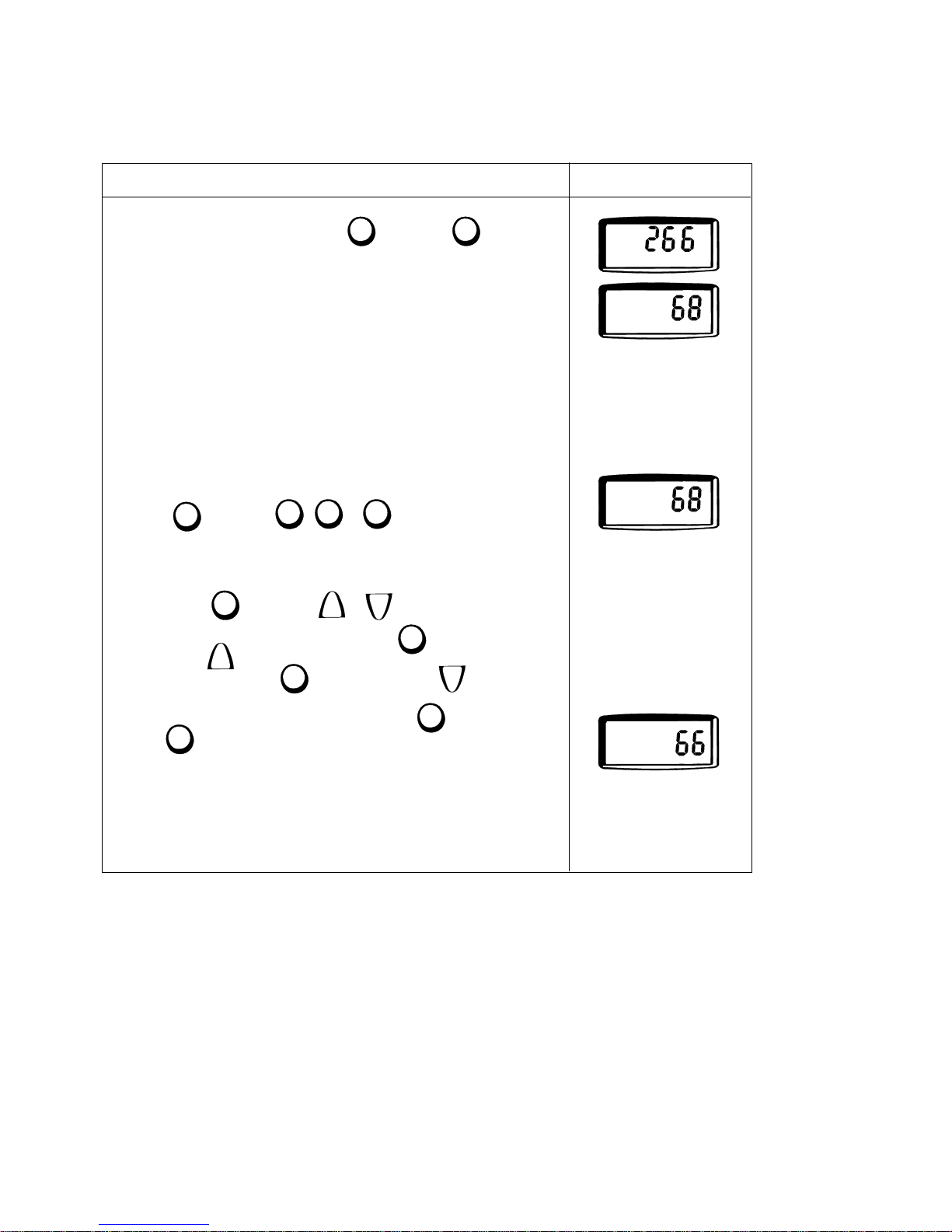
Calibrating the WDPL
For the WDPL to function correctly you have to calibrate your system. This has to be done before using the WDPL.
You only have to do this once.
If the buttons are not activated for 15 sec., the clock function will appear in the display.
It is not necessary to repeat the calibration when changing batteries.
2. Measure the height from desk to floor.
If only one desk is connected, - go to point 4.
3. Press and then press , or to select desk.
If only one desk is connected it is not possible to select Desk ll or lll.
4. Press and hold and then press or to adjust the height in the display.
Example:
The display will switch from e.g. 68 to 69, 70, 71 etc. when is pressed and
held and then is pressed.
and e.g. 68 to 67, 66 etc. when is pressed and held and then is pressed.
5. When the wanted height is shown in the display, press and hold and
then . The reference height of the desk will now be stored in the control box.
When the reference height is stored, the digits will be switched off for 1 sec. and
back on again.
Display view:
Action:
1. Switch between [cm] and [inch]. Press and hold and then press
Desk IUser
I
.
"
Desk
I
User
I
Desk
I
User
I
Store
Store
User
Desk
l
ll
lll
Store
v
v
Store
v
Store
v
Store
Desk
Desk
I
User
I
Page 31
Page 31 of 44
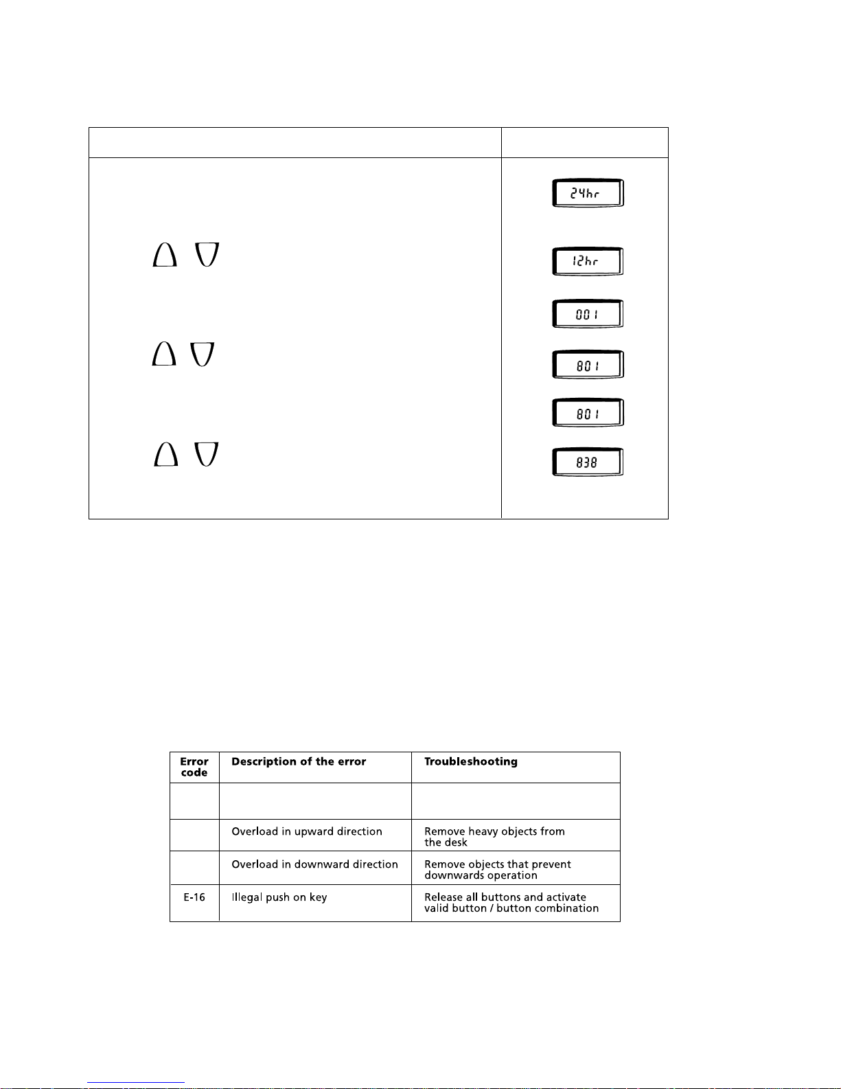
Adjusting the clock
The clock is now activated.
1. Press the “clock button” using a ball pen.
24hr mode (European time mode) is default - can be changed to 12hr mode
(US time mode)
Changing time mode:
Press or
(Press the “clock button” again to confirm “time mode” using a ball pen)
2. Press or to adjust “hh”
3. Press the “clock button” again to confirm “hh”.
4. Press or to adjust “mm”
5. Press the clock button again to confirm “mm”
Display view:
Action:
Flashing
Flashing
hh is flashing
Switches to PM if hh > 11
mm is flashing
Example:
AM
PM
.
.
AM
.
PM
.
.
PM
.
.
PM
.
v
v
v
v
v
v
Troubleshooting (WDPL):
If errors occur the error code appears in the display - The “error” segment flashes (1 Hz).
E-02
E-03
E-01
Position lost
Initialise
Page 32
Page 32 of 44
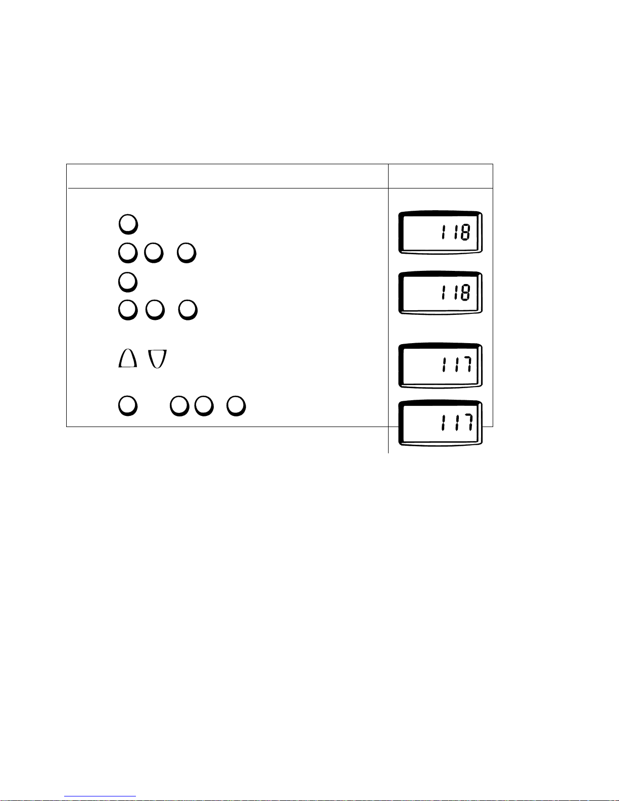
Store a memory position
3 users can store 3 memory posistions each. The connected desks (max. 3) are to be adjusted individually - one at a time.
Quick setup:
On the back of the WDP you will find a quick guide for storing a memory position.
The position is now stored in the control box.
To store a new memory position on the same desk, go through points 3 to 6 again.
If the buttons are not activated for 15 sec., the clock function will appear in the display.
If only one desk is connected, - go to point 4.
1. Press
2. Press , or until the wanted desk is shown in the display.
3. Press
4. Press , or until the wanted user is shown in the display
5. Press or until the wanted height is obtained.
6. Press and then , or
Display view:
Action:
Flashing
Flashing
Example:
lll
ll
l
Store
v
v
lll
ll
l
User
lll
ll
l
Desk
DeskIUserIPosition
II
Store
DeskIUser
I
DeskIUser
I
DeskIUser
I
Page 33
Page 33 of 44
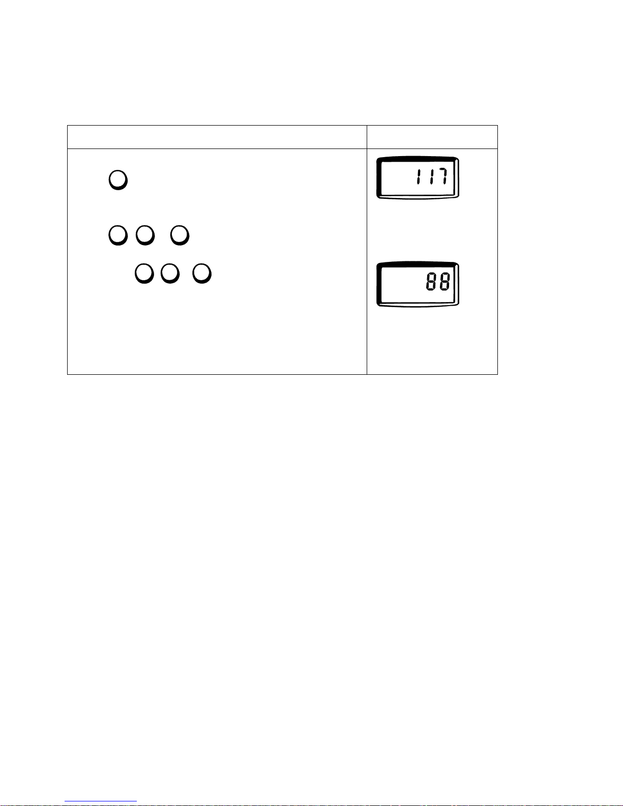
Switch to a stored memory position
Quick setup:
On the back of the WDP you will find a quick guide for storing a memory position.
1. Press
2. Press , or until the wanted user is shown in the display
3. Press and hold , or until all desks have reached their memory position.
The display will show the height of the moving desk for about 15. sec.
Display view:
Action:
Position l is flashing digits counting from
117 to 88. When the desk
has reached the new height
position l it will stop flashing.
Example:
User
l
ll
lll
l
ll
lll
DeskIUser
III
DeskIUser
III
Position
I
Flashing
If the buttons are not activated for 15 sec., the clock function will appear in the display.
Page 34

Page 34 of 44
Disposal of LINAK’s products
As LINAK’s customers often ask us how our products can be disposed of or scrapped we have prepared this guidance that
enables a classification to different waste fractions for recycling or combustion.
Guidance
We recommend that our products be disassembled as much as possible and divided into different waste groups for recycling or
combustion.
For example, waste can be sorted into metals, plastics, cable scrap, combustible material and recoverable resources.
Some of these main groups can be further divided into subgroups; e.g. metal can be divided into steel/aluminium/copper and
plastic can be divided into ABS/PA/PE/PP.
As an example, the table below breaks down the different components in LINAK products to various recycling groups:
Product Components Recycling group
Handset/Control: Plastic housing
Cable
PCB board
Plastic recycling or combustion
Cable scrap or combustion
Electronics scrap
By now, almost all our casted plastic parts are supplied with an interior code for plastic type and fibre contents, if any.
Main groups of disposal
Product main
groups
Metal
Scrap
Cable
scrap
Electronics
scrap
Plastic recycling or
combustion
Comments
DPXX X X X
WDPL X X X
Disposal of batteries
"Details regarding safe disposal of used and leaking batteries:
Batteries should be disposed in accordance with appropriate federal, state and local regulations. LINAK recommends that
used or leaking batteries are disposed through local recycling system. Please do not throw used or leaking batteries in normal
household waste or in nature. This will cause damage to the enviroment.
How to deal with leaking batteries
Leaking batteries should be disposed as described above.
If leaking batteries are discovered in the product, the batteries must be removed at once to minimise damage to the product.
If leaking batteries are left in the product, it become defective.
It is recommended to use plastic gloves when handling leaking batteries. The contents of a leaking batteries can cause
chemical burns and respiratory irritation.
If exposed to the contents of a leaking battery, please wash with soap and water. If irritation persists, please seek medical
attention. In case of eye contact, please flush eyes thoroughly with water for 15 minutes and seek medical attention."
Page 35
Page 35 of 44
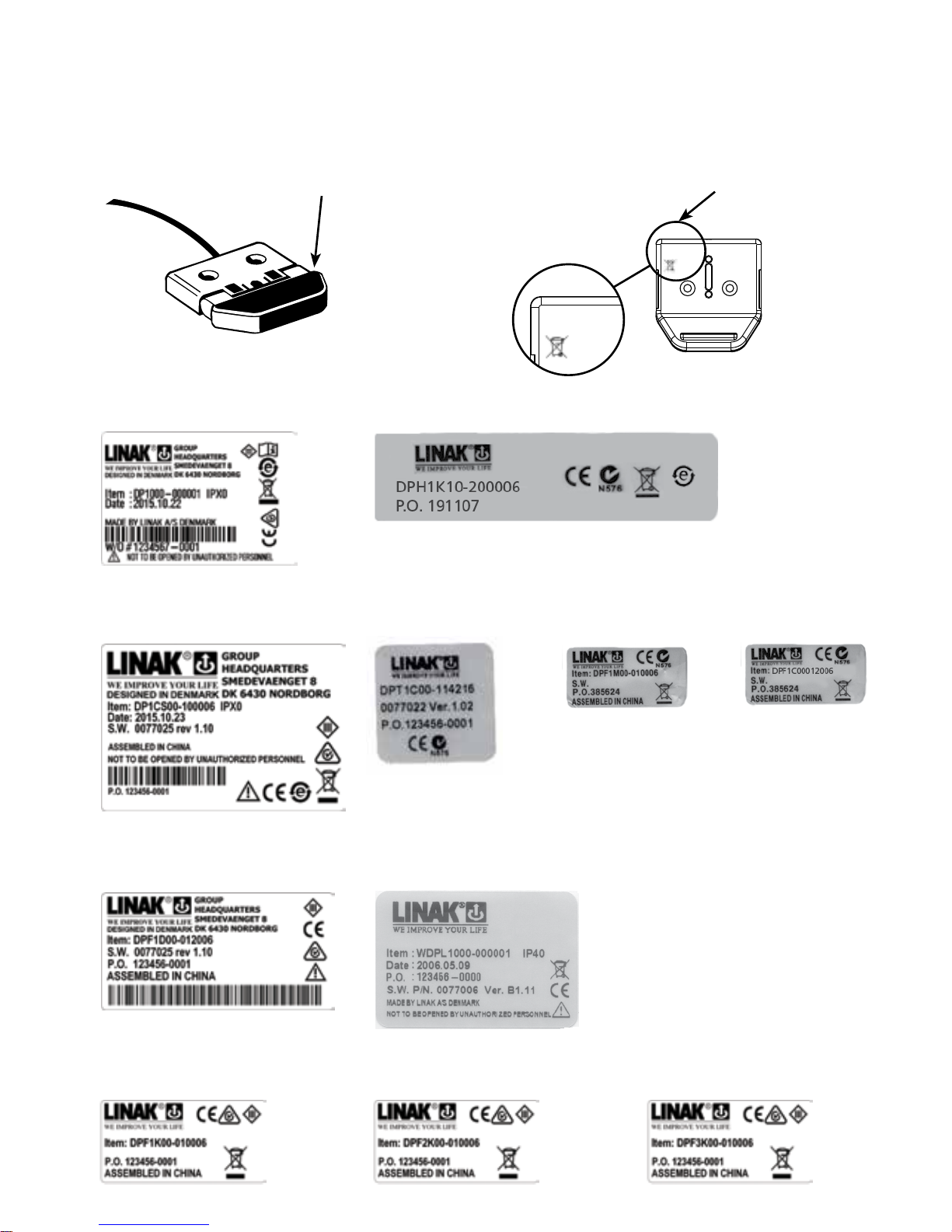
Labels
Label DPA
DPAK06 -B
02 0 6 03
The label is printed
directly on the DPA
Label for DPB
DPBK06
P.O.: 299218
DPBK06
P.O.: 299218
The label is printed
directly on the DPB
Label for WDPL
Label for DPF
Label for DPF1C
Label for DPT
Label for DPH
Label for DP1CS
Label for DPF1D
Label for DPF1K
Label for DPF2K
Label for DPF3K
Label for DP
Page 36
Page 36 of 44
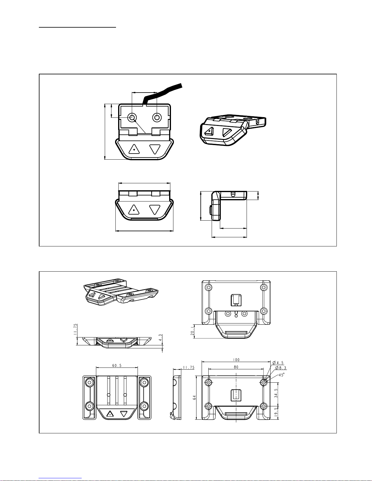
DESKLINE®
DRAWING APPENDIX
DPB with drawer
DPA
55.5
49.6
33.5
25.5
8
28
Ø4.4
24
53.4
13
157.5°
135°
112.5°
Page 37
Page 37 of 44
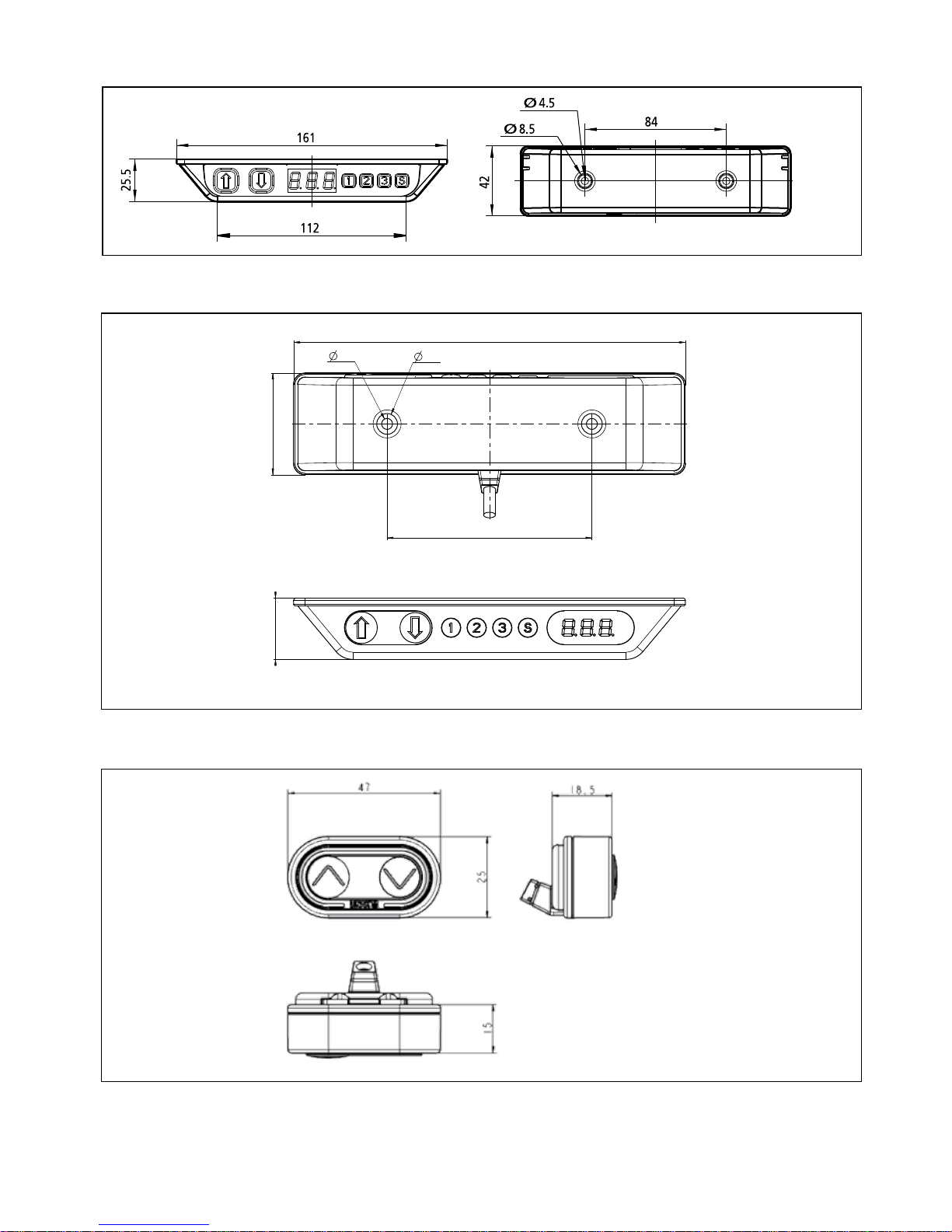
DP1C Desk Panel
DPF1K Desk Panel
DP1CS Desk Panel
161
84
42
8.5
4.5
25.5
Page 38
Page 38 of 44
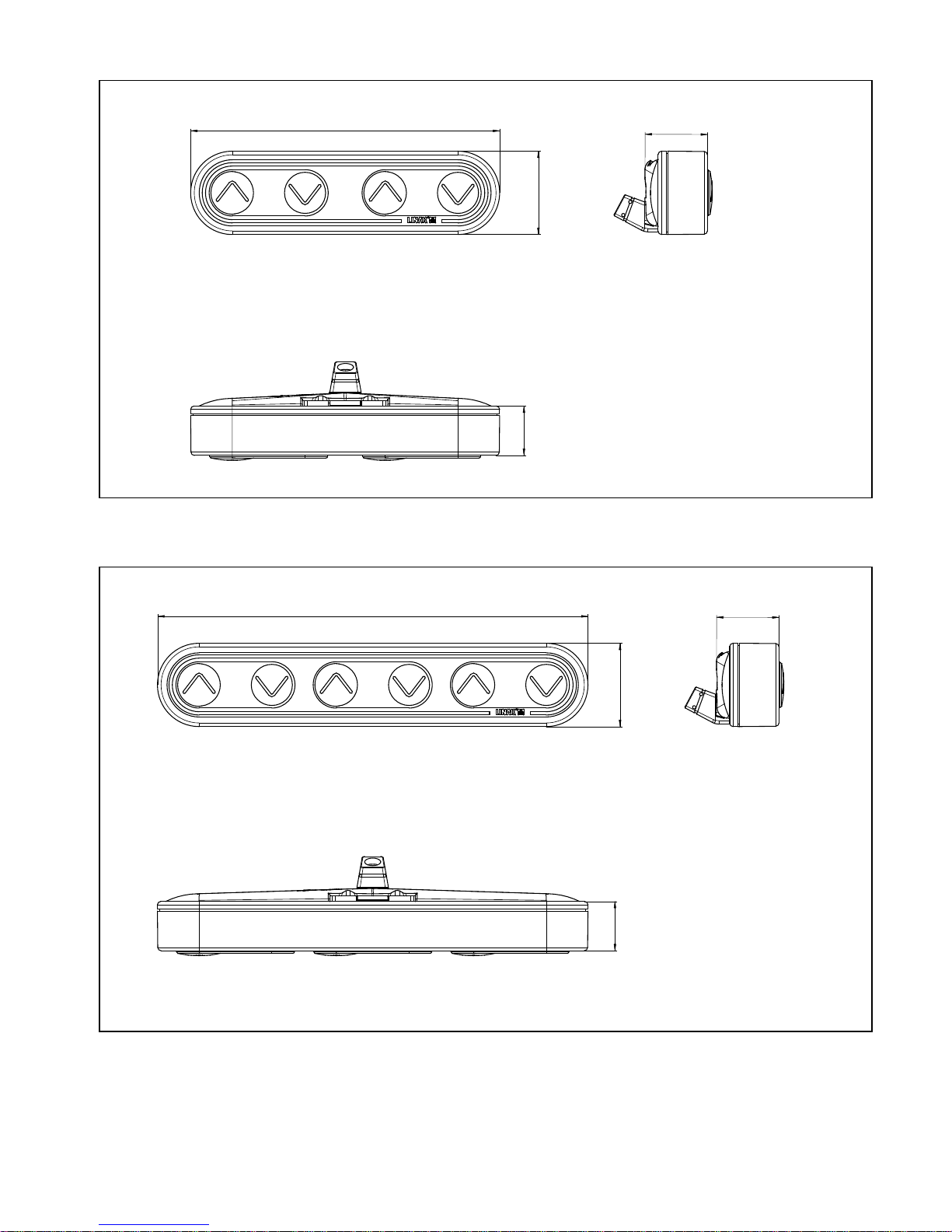
DPF3K Desk Panel
130
25.5
18.5
15
DPF2K Desk Panel
93.5
25.5
18.5
15
Page 39
Page 39 of 44
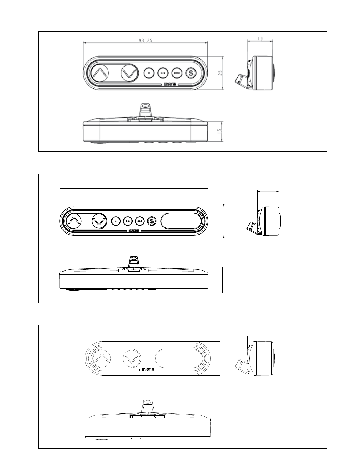
DPF1C Desk Panel with display
130
25
19
15
DPF1D Desk Panel
DPF1M Desk Panel
93.5
18.5
15
25.5
Page 40
Page 40 of 44
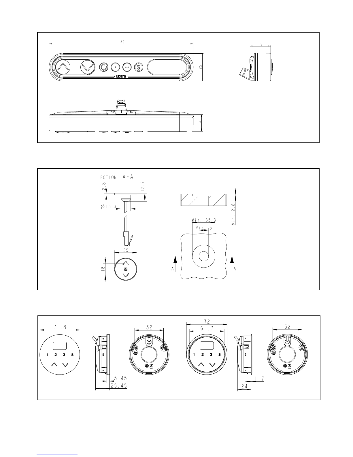
DPH Desk Panel
DPT Desk Panel
DPF4T Desk Panel
Page 41
Page 41 of 44
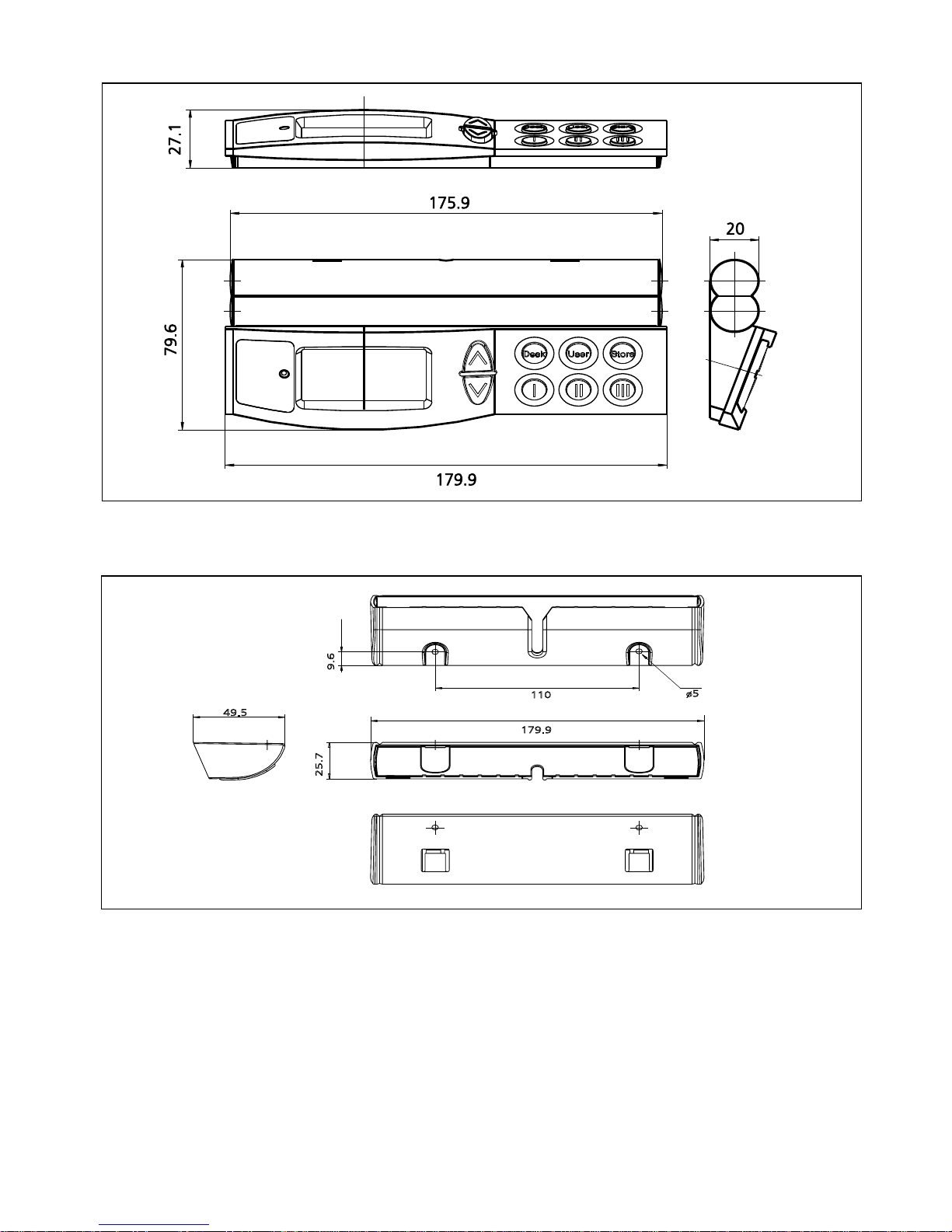
WDP fitting for desk
110
179.9
49.5
ø5
9.6
25.7
WDP
Page 42
Page 42 of 44
Page 43

Page 43 of 44
LINAK APPLICATION POLICY
The purpose of the application policy is to define areas of responsibilities in relation to applying a LINAK product defined as
hardware, software, technical advice, etc. related to an existing or new customer application.
LINAK products as defined above are applicable for a wide range of applications within the Medical, Furniture, Desk and
Industry areas. Yet, LINAK cannot know all the conditions under which LINAK products will be installed, used, and operated, as
each individual application is unique.
The suitability and functionality of the LINAK product and its performance under varying conditions (application, vibration,
load, humidity, temperature, frequency, etc.) can only be verified by testing, and shall ultimately be the responsibility of the
LINAK customer using any LINAK product.
LINAK shall be responsible solely that the LINAK products comply with the specifications set out by LINAK and it shall be the
responsibility of the LINAK customer to ensure that the specific LINAK product can be used for the application in question.
Page 44

Page 44 of 44
Copyright
©
LINAK 2017.06 . MA-M9-02-350-i LINAK A/S reserve the right to make technical alterations
Terms of use
The user is responsible for determining the suitability of LINAK products for specific application. LINAK takes great care in providing accurate and up-todate information on its products.
However, due to continuous development in order to improve its products, LINAK products are subject to frequent modifications and changes without
prior notice. Therefore, LINAK cannot guarantee the correct and actual status of said information on its products.
While LINAK uses its best efforts to fulfil orders, LINAK cannot, for the same reasons as mentioned above, guarantee the availability of any particular
product. Therefore, LINAK reserves the right to discontinue the sale of any product displayed on its website or listed in its catalogues or other written
material drawn up by LINAK.
All sales are subject to the Standard Terms of Sale and Delivery for LINAK. For a copy hereof, please contact LINAK.
FACTORIES
CHINA
LINAK (Shenzhen) Actuator Systems, Ltd.
Phone: +86 755 8610 6656
Fax: +86 755 8610 6990
E-mail: [email protected] . www.linak.cn
DENMARK - Group Headquarters
LINAK A/S, Guderup
Phone: +45 73 15 15 15
Fax: +45 74 45 80 48
Fax: +45 73 15 16 13 (Sales)
E-mail: [email protected] . www.linak.com
SUBSIDIARIES
AUSTRALIA
LINAK Australia Pty. Ltd
Phone: +61 3 8796 9777
Fax: +61 3 8796 9778
E-mail: [email protected] . www.linak.com.au
AUSTRIA
LINAK Repräsentanz Österreich (Wien)
Phone: +43 (1) 890 7446
Fax: +43 (1) 890 744615
E-mail: [email protected] . www.linak.at
BELGIUM & LUXEMBOURG
LINAK Actuator-Systems NV/SA
Phone: +32 (0)9 230 01 09
Fax: +32 (0)9 230 88 80
E-mail: [email protected] . www.linak.be
BRAZIL
LINAK Do Brasil Comércio De
Atuadores Ltda.
Phone: +55 (11) 2832 – 7070
Fax: +55 (11) 2832 – 7060
E-mail: [email protected] . www.linak.com.br
CANADA
LINAK Canada Inc.
Phone: +1 502 253 5595
Fax: +1 416-255-7720
E-mail: [email protected] . www.linak-us.com
CZECH REPUBLIC
LINAK C&S S.R.O.
Phone: +420581741814
Fax: +420581702452
E-mail: [email protected] . www.linak.cz
DENMARK - Sales
LINAK Danmark A/S
Phone: +45 86 80 36 11
Fax: +45 86 82 90 51
E-mail: [email protected] . www.linak.dk
SLOVAKIA
LINAK Slovakia s.r.o.
Phone: +421 51 75 63 414
Fax: +421 51 75 63 410
E-mail: [email protected] . www.linak.com
USA
LINAK U.S. Inc.
North and South American Headquarters
Phone: +1 502 253 5595
Fax: +1 502 253 5596
E-mail: [email protected] . www.linak-us.com
FINLAND
LINAK OY
Phone: +358 10 841 8700
E-mail: [email protected] . www.linak.fi
FRANCE
LINAK France E.U.R.L
Phone: +33 (0) 2 41 36 34 34
Fax: +33 (0) 2 41 36 35 00
E-mail: [email protected] . www.linak.fr
GERMANY
LINAK GmbH
Phone: +49 6043 9655 0
Fax: +49 6043 9655 60
E-mail: [email protected] . www.linak.de
INDIA
LINAK A/S India Liaison Office
Phone: +91 120 4734613
Fax: +91 120 4786428
E-mail: [email protected] . www.linak.in
IRELAND
LINAK UK Limited - Ireland
Phone: +44 (0)121 544 2211
Fax: +44 (0)121 544 2552
+44 (0)796 855 1606 (UK Mobile)
+35 387 634 6554 (Republic Of
Ireland Mobile)
E-mail: [email protected] . www.linak.co.uk
ITALY
LINAK Italia S.r.l.
Phone: +39 02 48 46 33 66
Fax: +39 02 48 46 82 52
E-mail: [email protected] . www.linak.it
JAPAN
LINAK K.K.
Phone: 81-45-533-0802
Fax: 81-45-533-0803
E-mail: [email protected] . www.linak.jp
MALAYSIA
LINAK Actuators Sdn. Bhd.
Phone: +60 4 210 6500
Fax: +60 4 226 8901
E-mail: [email protected] . www.linak.my
NETHERLANDS
LINAK Actuator-Systems B.V.
Phone: +31 76 5 42 44 40
Fax: +31 76 5 42 61 10
E-mail: [email protected] . www.linak.nl
NEW ZEALAND
LINAK New Zealand Ltd.
Phone: +64 9580 2071
Fax: +64 9580 2072
E-mail: [email protected]
www.linak.com.au
NORWAY
LINAK Norge AS
Phone: +47 32 82 90 90
Fax: +47 32 82 90 98
E-mail: [email protected] . www.linak.no
POLAND
LINAK Polska
Phone: +48 22 295 09 70
E-mail: [email protected] . www.linak.pl
REPUBLIC OF KOREA
LINAK Korea Ltd.
Phone: +82-(0)2-6231-1515
Fax: +82-(0)2-6231-1516
E-mail: [email protected] . www.linak.kr
RUSSIAN FEDERATION
000 LINAK
Phone: +7 495 280 14 26
Fax: +7 495 687 14 26
E-mail: [email protected] . www.linak.ru
SPAIN
LINAK Actuadores, S.L.u
Phone: +34 93 588 27 77
Fax: +34 93 588 27 85
E-mail: [email protected] . www.linak.es
SWEDEN
LINAK Scandinavia AB
Phone: +46 8 732 20 00
Fax: +46 8 732 20 50
E-mail: [email protected] . www.linak.se
SWITZERLAND
LINAK AG
Phone: +41 43 388 31 88
Fax: +41 43 388 31 87
E-mail: [email protected] . www.linak.ch
TAIWAN
LINAK (Shenzhen) Actuator systems Ltd.
Taiwan Representative
Phone: +886 2 27290068
Fax: +886 2 27290096
Mobile: +886 989292100
E-mail: [email protected] . www.linak.com.tw
TURKEY
LINAK İth. İhr. San. ve Tic. A.Ş.
Phone: + 90 312 4726338
Fax: + 90 312 4726635
E-mail: [email protected] . www.linak.com.tr
UNITED KINGDOM
LINAK UK Limited
Phone: +44 (0)121 544 2211
Fax: +44 (0)121 544 2552
E-mail: [email protected] . www.linak.co.uk
DISTRIBUTORS
ARGENTINA
Novotec Argentina SRL
Phone: 011-4303-8989/8900
Fax: 011-4032-0184
E-mail: [email protected]
www.novotecargentina.com
COLOMBIA
MEM Ltda
Phone: +[57] (1) 334-7666
Fax: +[57] (1) 282-1684
E-mail: [email protected]
www.mem.net.co
INDIA
Mechatronics Control Equipments
India Pvt Ltd
Phone: +91-44-28558484/85
E-mail: [email protected]
www.mechatronicscontrol.com
INDONESIA
Pt. Himalaya Everest Jaya
Phone: +6 221 544 8956/8965
Fax: +6 221 619 4658/1925
E-mail: [email protected]
www.hej.co.id
IRAN
Bod Inc.
Phone: +98 2188998635-6
Fax: +98 2188954481
E-mail: [email protected] . www.bod.ir
RUSSIAN FEDERATION
000 FAM
Phone: +7 812 3319333
Fax: +7 812 3271454
E-mail: [email protected] . www.fam-drive.ru
SINGAPORE
Servo Dynamics Pte. Ltd.
Phone: +65 6844 0288
Fax: +65 6844 0070
E-mail: [email protected]
www.servo.com.sg
SOUTH AFRICA
Industrial Specialised Applications CC
Phone: +27 11 312 2292 or
+27 11 2077600 (Switch Board)
Fax: +27 11 315 6999
E-mail: [email protected]
www.isaza.co.za
UNITED ARAB EMIRATES
Mechatronics
Phone: +971 4 267 4311
Fax: +971 4 267 4312
E-mail: [email protected]
For contact details on other countries
please visit www.linak.com or contact:
LINAK INTERNATIONAL
Phone: +45 73 15 15 15
Fax: +45 74 45 90 10
Fax: +45 73 15 16 13 (Sales)
E-mail: [email protected] . www.linak.com
 Loading...