

Page 1

WTR Series 330-15000
Revision A
October 2002
Installation & Maintenance for
WTR-3 through WTR-575
Page 2

Page 3
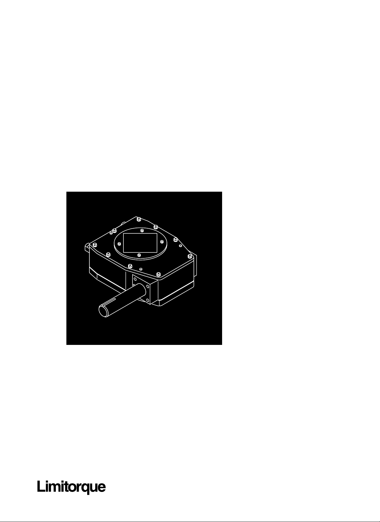
Installation & Maintenance for
WTR-3 through WTR-575
WTR Series
Page 4

Disclaimer
WTR Installation & Maintenance Manual 330-15000 • Revision A • August
WTR Series Installation & Maintenance Manual
for WTR-3 through WTR-575
©1999 Copyright Limitorque Corporation. All rights reserved.
Printed in the United States of America.
Disclaimer
No part of this book shall be reproduced, stored in a retrieval system, or transmitted by any
means, electronic, mechanical, photocopying, recording, or otherwise without the written
permission of Limitorque. While every precaution has been taken in the preparation of this
book, the publisher assumes no responsibility for errors or omissions. Neither is any liability
assumed for damages resulting from the use of the information contained herein.
This document is the proprietary information of Limitorque Corporation, furnished for
customer use ONLY. No other uses are authorized without written permission from
Limitorque Corporation.
Limitorque Corporation reserves the right to make changes, without notice, to this document and the products it describes. Limitorque Corporation shall not be liable for technical
or editorial errors or omissions made herein; nor for incidental or consequential damages
resulting from the furnishing, performance or use of this document.
This manual contains information that is correct to the best of Limitorque’s knowledge. It
is intended to be a guide and should not be considered as a sole source of technical
instruction, replacing good technical judgment, since all possible situations cannot be anticipated. If there is any doubt as to exact installation, configuration, and/or use, call Limitorque
Corporation‚ at (804) 528-4400.
The choice of system components is the responsibility of the buyer, and how they are used
cannot be the liability of Limitorque Corporation. However, Limitorque’s sales team and
application engineers are always available to assist you in making your decision. The latest
revisions to this document are available online at http://www.limitorque.com
IV
Page 5

WTR Series
Table of Contents
WTR Installation & Maintenance Manual 330-15000 • Revision A • August
Table of Contents
1 Introduction 1-1
1.1 Purpose 1-1
1.2 User Safety 1-1
2 Product Capabilities and Features 2-1
2.1 Initial Inspection and Storage Instructions 2-1
2.2 Product Identification 2-2
2.3 Inspection and Recording 2-2
2.4 Storage Procedure 2-3
3 Unit Weights 3-1
4 Installation Instructions 4-1
4.1 Safety Precautions 4-1
4.2 Safety Practices 4-1
4.3 Prepare Actuator 4-2
4.4 Installing WTR-3 through 150 4-4
4.5 Installing WTR-430 through 575 4-5
4.5.1 Two-Piece Drive Sleeve 4-5
4.5.2 One-Piece Drive Sleeve 4-5
4.6 Setting the Mechanical Stops on the WTR 4-6
5 Maintenance 5-1
5.1 Lubrication 5-1
5.1.1 Lubrication Inspection 5-1
5.1.2 Factory Lubricant 5-1
5.2 Minimum Lubricant Qualities Required 5-2
5.3 Disassemble and Reassemble 5-2
5.3.1 Disassemble WTR-3 through 150 5-3
5.3.2 Reassemble WTR-3 through 150 5-3
5.3.3 Disassemble SGA for WTR-15 through 150 5-3
5.3.4 Reassemble SGA for WTR-15 through 150 5-3
5.3.5 Disassemble WTR-430 through 575 5-4
5.3.5.1 Disassemble SGA 5-4
5.3.5.2 Disassemble WTR 5-4
5.3.6 Reassemble WTR-430 through 575 5-4
6 Parts Breakdown 6-1
7 How to Order Parts 7-1
V
Page 6

Figures / Tables
WTR Installation & Maintenance Manual 330-15000 • Revision A • August
Figures
Figure 2.1 – WTR gearbox 2-2
Figure 2.2 – WTR nameplates 2-2
Figure 4.1 – WTR Splined Adapter removal 4-2
Figure 4.2 – Worm gear quadrant adjusted to contact with mechanical
stops to set mechanical stop screw position 4-6
Figure 6.1 – WTR with SGA parts breakdown (3 through 150) 6-1, 6-2
Figure 6.2 – WTR with SGA parts breakdown (430 through 575) 6-3, 6-4
Tables
Table 3.1 – Unit weights 3-1
Table 4.1 – Splined Adapter custom bore and keyway sizes 4-3
Table 4.2 – WTR mounting base tap sizes (3 through 150) 4-4
Table 4.3 – WTR mounting base tap sizes (430 through 575) 4-5
Table 5.1 – Alternate Factory Lubricants 5-1
Table 5.2 – Lubricant Quantities 5-2
VI
Page 7

WTR Series
Introduction
WTR Installation & Maintenance Manual 330-15000 • Revision A • August
1 Introduction
1.1 Purpose
This Installation and Maintenance Manual explains how to install and maintain the WTR
actuator. Information on installation, disassembly, lubrication, and spare parts is provided.
1.2 User Safety
Safety notices in this manual detail precautions the user must take to reduce the risk of
personal injury and damage to the equipment. The user must read and be familiar with these
instructions before attempting installation, operation, or maintenance. Failure to observe
these precautions could result in serious bodily injury, damage to the equipment, void of the
warranty, or operational difficulty.
Safety notices are presented in this manual in three forms:
a WARNING: Refers to personal safety. Alerts the user to potential danger. Failure to follow
warning notices could result in personal injury or death.
CAUTION: Directs the user’s attention to general precautions that, if not followed, could
result in personal injury and/or equipment damage.
NOTE: Highlights information critical to the user’s understanding of the actuator’s installa-
tion and operation.
1-1
Page 8

WTR Installation & Maintenance Manual 330-15000 • Revision A • August
This page is intentionally blank.
1-2
Page 9

WTR Series
Product Capabilities and Features
WTR Installation & Maintenance Manual 330-15000 • Revision A • August
2 Product Capabilities and Features
Designed to operate 90° applications WTR series worm gear actuators are designed to operate
valves or other applications that require 90° operation such as butterfly, ball, and plug valves.
Can be hand-operated with a handwheel or 2" nut, or electrically operated with an added
motorized actuator.
Designed for use in Commercial service and AWWA C504-87 and 540-93 standards The
Commercial service series uses a ductile iron worm gear with a hardened steel worm. The
AWWA service series uses an alloy bronze worm gear and hardened steel worm.
The WTR has flexibility built into its design
Removable Splined Adapter to accommodate simple installation The actuator has a drop-in
splined adapter to allow easy incremental adjustments when aligning the valve stem keyway
and the actuator positions.
Removable/Interchangeable Mounting Base for easy input shaft position and mounting base
changes for Units WTR-3 through 150
The handwheel/input shaft assembly position is
changed by unbolting the housing cover and baseplate from the WTR main housing,
inverting the housing 180°, and bolting the cover and the baseplate back to the WTR main
housing.
a WARNING: Always isolate valve before reversing assembly position.
The WTR accommodates other components such as spur gear attachments and electric actua-
tors. For WTR-3 through 150, combinations of these components can be added without
removing the input shaft assembly.
O-ring sealed and permanently lubricated for reduced maintenance.
2.1 Initial Inspection and Storage Instructions
a WARNING: Read this Installation and Maintenance Manual carefully and
completely before attempting to store the actuator. If an electric actuator is attached
to the WTR manual actuator, be aware of the electrical hazards.
2-1
Page 10
Product Capabilities and Features
WTR Installation & Maintenance Manual 330-15000 • Revision A • August
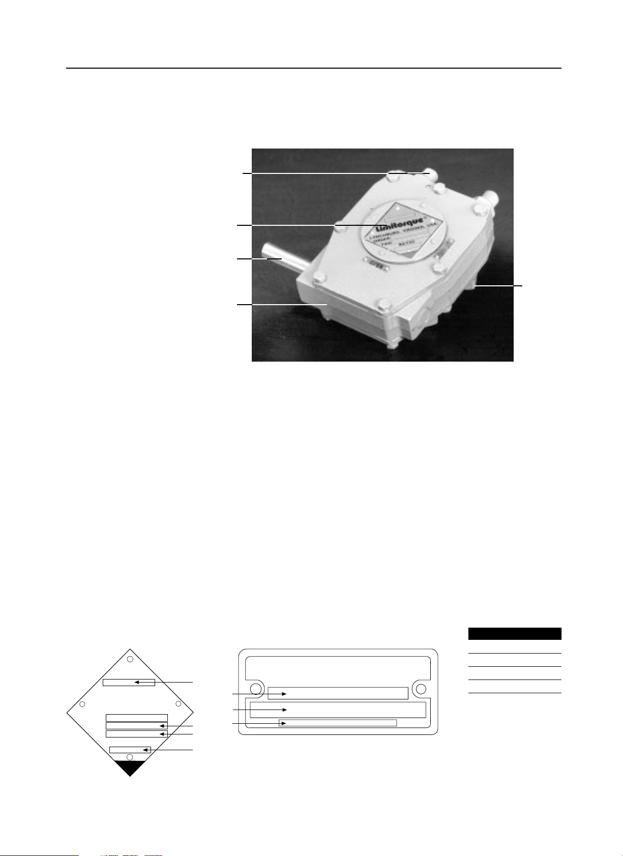
2.2 Product Identification
Figure 2.1 – WTR gearbox
2.3 Inspection and Recording
Upon receipt of the actuator, inspect the condition of the equipment and record nameplate
information as follows:
1. Carefully remove actuator from shipping carton or skid. Thoroughly examine the
equipment for any physical damage that may have occurred during shipment. If damaged,
immediately report the damage to the transport company.
2. A nameplate is attached to each actuator with the following information:
• Unit Size
• Limitorque Order Number
• Customer Tagging
• Unit Ratio (includes WTR SGA if attached to unit - does not include motorized actuator
ratios)
Record this information for future reference, i.e., ordering parts, obtaining further
information.
Figure 2.2 – WTR nameplates
2-2
Mechanical
Stop Screw
Nameplate
Input Shaft
Mounting
Base
Housing
WTR-3 through 150 WTR-430 through 575
WTR
LIMITORQUE
LYNCHBURG, VIRGINIA, USA
SERIAL
ORDER
TAG
RATIO
1
2
3
2
3
4
1
LIMITORQUE
Piece Description
1 Unit Size
2 Order Number
3 Customer Tag
4 Unit Ratio
Page 11

WTR Series
Product Capabilities and Features
WTR Installation & Maintenance Manual 330-15000 • Revision A • August
2.4 Storage Procedure
NOTE: The following is our recommended storage procedure to retain maximum product
integrity during storage. Failure to comply with recommended procedure will void the
warranty.
Storage (less than 1 year)
Store actuators on wooden skids to protect the machined mounting flange. Place the wooden
skids containing the actuators in a clean, dry, protected warehouse. If the actuators must be
stored outside, they must be covered in polyethylene protection with silica gel crystals to
absorb moisture. If an electric actuator is attached to the WTR actuator, refer to the storage
procedures in its respective manual for appropriate storage procedures. Rotate input shafts
every three months to mix the lubricant.
2-3
Page 12

WTR Installation & Maintenance Manual 330-15000 • Revision A • August
This page is intentionally blank.
2-4
Page 13

WTR Series
Unit Weights
WTR Installation & Maintenance Manual 330-15000 • Revision A • August
3 Unit Weights
The approximate weights of the WTR actuators, with and without Spur Gear Attachments
(SGA), are provided below.
Table 3.1 – Unit weights
Commercial Unit Size/SGA AWWA Unit Size/SGA Lbs Kg
WTRC-3 N/A 14 7
WTRC-5 N/A 14 7
WTRC-10 WTRA-12 34 15
WTRC-15 WTRA-21 59 27
WTRC-15/S1.7 WTRA-21/S1.7 75 34
WTRC-28 WTRA-36 78 35
WTRC-28/S3.0 WTRA-36/S3.0 108 49
WTRC-40 WTRA-48 126 57
WTRC-40/S3.7 WTRA-48/S3.7 157 71
WTRC-60 WTRA-72 194 88
WTRC-60/S4.6 WTRA-72/S4.6 224 102
WTRC-150 WTRA-130 290 132
WTRC-150/S8.25 WTRA-130/S8.25 360 163
WTRC-430 WTRA-430 340 154
WTRC-450 WTRA-450 413 187
WTRC-500 WTRA-500 518 235
WTRC-575 WTRA-575 1262 572
3-1
Page 14

WTR Installation & Maintenance Manual 330-15000 • Revision A • August
This page is intentionally blank.
3-2
Page 15

4 Installation Instructions
4.1 Safety Precautions
a WARNING: Read this Installation and Maintenance Manual carefully and
completely before attempting to install, operate, or troubleshoot the Limitorque
WTR actuator. Be aware of electrical hazards if an electric actuator is attached to the
WTR manual actuator. Be aware of high-pressure hazards associated with the
attached valve or other actuated device when installing or performing maintenance
on your WTR actuator.
a WARNING: Do not overtorque the WTR actuator or operate the actuator with
devices other than installed operating equipment such as the handwheel, chainwheel,
2" AWWA nut or other factory-installed equipment. Using force beyond the ratings
of the unit and/or using additive force devices such as cheater bars, wheel wrenches,
pipe wrenches or other devices on the actuator handwheel may cause serious personal
injury and/or damage to the actuator or valve.
a WARNING: Do not overtorque the WTR actuator when using a Power-Take-Off
Drive (PTO) to operate the 2" AWWA nut. Using force beyond the ratings of the unit
may cause serious personal injury and/or damage to the actuator or valve.
a WARNING: Potential HIGH-PRESSURE vessel - Before installing the WTR on a
valve that is in service, ensure that the valve or other actuated device is isolated from
operation and the associated pipeline is not under pressure.
a WARNING: Do not attempt to remove the WTR from a valve on a pressurized line.
The WTR has self-locking gears that will stabilize the valve until pressure on the line
is under control or removed.
4.2 Safety Practices
The following check points should be performed to maintain safe operation of the WTR
actuator:
• Set up a periodic operating schedule on infrequently used valves.
• Verify that the pointer cap has been replaced after the gear operator is installed.
• Verify that the “end-of-travel” stop screws are correctly adjusted.
• Verify that the limit and/or torque switches on any electric actuator fitted to the WTR are
correctly and appropriately adjusted.
WTR Series
Installation Instructions
WTR Installation & Maintenance Manual 330-15000 • Revision A • August4-1
Page 16
Installation Instructions
WTR Installation & Maintenance Manual 330-15000 • Revision A • August
4.3 Prepare Actuator
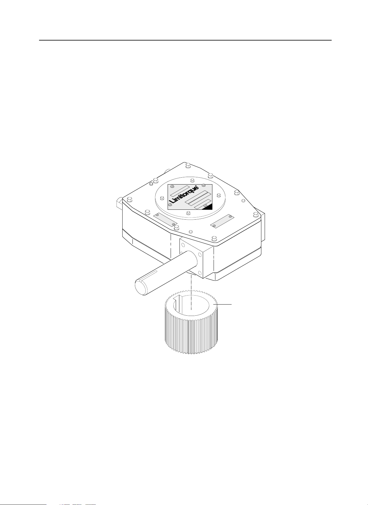
1. Remove the S plined Adapter from the bottom of the actuator. (See Figure 4.1 below.)
NOTE: The valve manufacturer is responsible for assuring that the Splined Adapter is
retained within the WTR actuator. Retaining the Splined Adapter is accomplished by
ensuring the Valve/Actuator Mounting Flange is sized to retain the Splined Adapter or by
using the Setscrew that is threaded through the Splined Adapter. Setscrews are provided
only if the Splined Adapter has been bored and keyed at the factory.
NOTE: A Splined Adapter is equivalent to a two-piece drive sleeve.
Figure 4.1 – WTR Splined Adapter removal
4-2
USA.
LYNCHBURG, VIRGINIA,
ORDER
OPEN
RATIO
TAG
SHUT
Splined Adapter
Page 17

WTR Series
Installation Instructions
WTR Installation & Maintenance Manual 330-15000 • Revision A • August
2. If the Splined Adapter has been bored and keyed by Limitorque, verify dimensions to
ensure proper compatibility with the valve stem.
NOTE: If Splined Adapter is not factory-machined, the customer assumes responsibility
for securing the adapter to the valve stem so it will not disengage from the shaft.
3. If the Splined Adapter has not been bored and keyed by Limitorque, it is provided solid or
with a minimum pilot bore. Custom bore and key to the maximum permissible sizes as
listed in Table 4.1.
Table 4.1 – Splined Adapter custom bore and keyway sizes
Commercial AWWA Key size in max bore Key size in max bore
Unit size Unit size Max bore (in) Rect. key Sq. key Max bore (mm) Metric key
WTRC-3 N/A 1.25 1/4 x 3/16 0.250 28 8 x 7
WTRC-5 N/A 1.50 3/8 x 1/4 5/16 38 10 x 8
WTRC-10 WTRA-12 2.25 1/2 x 3/8 3/8 58 16 x 10
WTRC-15 WTRA-21 2.75 3/4 x 1/2 5/8 70 20 x 12
WTRC-28 WTRA-36 3.25 7/8 x 5/8 3/4 82 22 x 14
WTRC-40 WTRA-48 3.75 7/8 x 5/8 3/4 96 28 x 16
WTRC-60 WTRA-72 4.00 1 x 3/4 7/8 102 28 x 16
WTRC-150 WTRA-130 5.00 1-1/4 x 7/8 1 127 32 x 18
Drive sleeve 1 pc 2 pc 1 pc 2 pc 1 pc 2 pc 1 pc 2 pc 1 pc 2 pc
WTRC-430 WTRA-430 5.50 4.438 1.25 x 0.875 1 x 0.75 1.25 1.0 140 N/A 36 x 20 N/A
WTRC-450 WTRA-450 6.00 4.50 1.5 x 1 1.00 x 0.75 1.50 1.0 152 N/A 40 x 22 N/A
WTRC-500 WTRA-500 7.00 5.938 1.75 x 1.50 1.50 x 1.00 1.75 1.25 178 N/A 45 x 25 N/A
WTRC-575 WTRA-575 8.00 6.50 2.00 x 1.50 1.50 x 1.00 1.75 1.5 203 N/A 50 x 28 N/A
4-3
Page 18

Installation Instructions
WTR Installation & Maintenance Manual 330-15000 • Revision A • August
4.4 Installing WTR-3 through 150
CAUTION: If your actuator is already mounted to a valve from the manufacturer, verify
that the actuator is mounted according to the following instructions. Failure to follow
the installation procedures could result in personal injury or improper operation and
could damage the equipment.
Install actuator as follows:
NOTE: Piece numbers correspond to piece numbers listed in Figure 6.1.
1. Place valve in MID-TRAVEL position.
2. Install the Splined Adapter (piece #24) on the valve shaft and insert the Key to secure the
Splined Adapter. If the Splined Adapter has been factory-machined, insert and tighten the
Setscrew into the Splined Adapter tapped hole to secure it to the valve stem.
3. Remove Pointer Cap (piece #5) to view the Worm Gear (Drive Sleeve - piece #4) and the
Splined Adapter while mounting onto the valve flange and setting Mechanical Stop
Screws (piece #13) and Jam Nut (piece #14).
4. Adjust the WTR Worm Gear to approximate MID-TRAVEL position. Figure 4.2 shows
gear in closed position.
5. Align and mount the WTR on the installed Splined Adapter. Once the unit is properly
aligned on the valve Mounting Flange, secure the unit with the required number of
mounting bolts. High strength (minimum SAE-Grade 5) hex head or socket head cap
screws with lockwashers are recommended. The quantity and thread size of the actuator
mounting taps are listed in Table 4.2.
Table 4.2 – WTR mounting base tap sizes (3 through 150)
Commercial AWWA Tap size and quantity Standard Flange
Unit size/SGA Unit size/SGA MSS ISO MSS ISO
WTRC-3 N/A N/A (4) M8-1.25 x 12 deep N/A F07
70.00 B.C.
WTRC-5 N/A (4) 3/8-16 x .56 deep (4) M10-1.50 x 15 deep FA10 F10
4.000 B.C. 102.00 B.C.
WTRC-10 WTRA-12 (4) 1/2-13 x .750 deep (4) M12-1.75 x 18 deep FA12 F12
4.950 B.C. 125.00 B.C.
WTRC-15 WTRA-21 (4) 5/8-11 x .9 deep (4) M16-2 x 25 deep FA14 F14
WTRC-15/S1.7 WTRA-21/S1.7 5.500 B.C. 140.00 B.C.
WTRC-28 WTRA-36 (4) 3/4-10 x 1.12 deep (4) M20-2.5 x 30 deep FA16 F16
WTRC-28/S3.0 WTRA-36/S3.0 6.500 B.C. 165.00 B.C.
WTRC-40 WTRA-48 (8) 5/8-11 x .9 deep (4) M20-2.5 x 24 deep FA19 F16
WTRC-40/S3.7 WTRA-48/S3.7 7.500 B.C. 165.00 B.C.
WTRC-60 WTRA-72 (8) 5/8-11 x .9 deep (8) M16-2 x 24 deep FA25 F25
WTRC-60/S4.6 WTRA-72/S4.6 10.00 B.C. 254.00 B.C.
WTRC-150 WTRA-130 (8) 3/4-10 x 1.1 deep (8) M20-2.5 x 32 deep FA30 F30
WTRC-150/S8.3 WTRA-130/S8.3 11.750 B.C. 298.00 B.C.
4-4
Page 19

WTR Series
Installation Instructions
WTR Installation & Maintenance Manual 330-15000 • Revision A • August
4.5 Installing WTR-430 through 575
CAUTION: If the actuator is already mounted to a valve from the manufacturer, verify
that the actuator is mounted according to the following instructions. Failure to follow
the installation procedures could result in personal injury or improper operation and
could damage the equipment.
4.5.1 Two-Piece Drive Sleeve
Install actuator as follows:
NOTE: Piece numbers correspond to piece numbers listed in Figure 6.2.
1. Place valve in MID-TRAVEL position.
2. Place WTR in MID-TRAVEL position. Pointer Cap (piece #7) should be halfway
between open and close position.
3. Install the Splined Adapter (piece #32) on the valve shaft and insert the Key to secure the
Splined Adapter. If the Splined Adapter has been factory-machined, insert and tighten the
Setscrew into the Splined Adapter tapped hole to secure it to the valve stem.
4. Remove Pointer Cap (piece #7) to view the Worm Gear (Drive Sleeve - piece #5) and the
Splined Adapter while mounting onto the valve flange and setting Mechanical Stop
Screws (piece #22) and Nut (piece #24).
5. Align and mount the WTR on the installed Splined Adapter. Once the unit is properly
aligned on the valve Mounting Flange, secure the unit with the required number of
mounting bolts. High strength (minimum SAE-Grade 5) hex head or socket head cap
screws with lockwashers are recommended. The quantity and thread size of the actuator
mounting taps are listed in Table 4.3.
4.5.2 One-Piece Drive Sleeve
Install as follows:
NOTE: Piece numbers correspond to piece numbers listed in Figure 6.2.
1. Place valve in closed position.
2. Remove the Pointer Cap (piece #7) from the actuator.
3. Turn operator input shaft until gear unit is in fully closed position (verify correct rotation).
4. Mount the WTR on the valve Mounting Flange, locating the valve Shaft Key in the
keyway of the operator drive sleeve.
5. Bolt the WTR securely to the Mounting Flange. The quantity and thread size of the
actuator mounting taps are listed in Table 4.3.
Table 4.3 – WTR mounting base tap sizes (430 through 575)
Commercial AWWA Tap size and quantity Standard Flange
Unit size/SGA Unit size/SGA MSS ISO MSS ISO
WTRC-430 WTRA-430 (8) 1 - 8 x 1.3 deep, 14.02 B.C. (8) M30 - 3.5 x 34 deep, 356.00 B.C. FA35 F35
WTRA-450 WTRA-450 (8) 1 - 8 x 1.8 deep, 14.02 B.C. (8) M30 - 3.5 x 34 deep, 356.00 B.C. FA35 F35
WTRA-500 WTRA-500 (8) 1.25 - 7 x 1.97 deep, 16.00 B.C. (8) M36 - 4 x 50 deep, 406.00 B.C. FA40 F40
WTRC-575 WTRA-575 (12) 1.25 - 7 x 2.05 deep, 19.02 B.C. (8) M36 - 4 x 52 deep, 483.00 B.C. FA48 F48
4-5
Page 20
WTR Series
Installation Instructions
WTR Installation & Maintenance Manual 330-15000 • Revision A • August
4.6 Setting the Mechanical Stops on the WTR
• If the WTR is shipped already installed on the valve, the Mechanical Stops should be set.
• If the WTR is not installed on the valve, the Mechanical Stops must be set after mounting.
The following instructions for setting the Mechanical Stops are based on the typical orientation (Position B) for most actuator applications: turn handwheel Clockwise to CL OSE and
Counterclockwise to OPEN.
Set or reset the stops as follows:
NOTE: Piece numbers correspond to piece numbers listed on Figure 6.1 or 6.2.
1. Set CLOSE Mechanical Stop Screw (piece #13/#22): loosen the Locking Nut (piece
#14/#23) and back off the Mechanical Stop Screw (piece #13/#22) to allow the valve to
travel to the fully CLOSED position.
2. Using the Handwheel, turn the valve to the CLOSE position. The valve must be fully
seated before setting the CLOSE mechanical stop.
NOTE: If the actuator is motor-operated, engage the Declutch Lever to put the electric
actuator in the manual mode. Use the electric actuator Handwheel for manual operation.
3. Rotate the Mechanical Stop Screw (piece #13/#22) in the clockwise direction until
contact is made with the Drive Sleeve (piece #4/#5).
CAUTION: When using an electric actuator, do not allow mechanical stops to be used
to torque against. Use the limit switch.
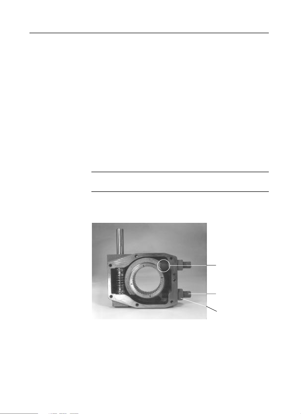
Figure 4.2 – Worm gear quadrant adjusted to contact with mechanical stops to set mechanical stop
screw position
4-6
Mechanical Stop Set
Screw & Worm Gear
adjusted for typical CLOSE
position
#13 Mechanical Stop
Screw
#14 Locking Nut
Page 21

Installation Instructions
WTR Installation & Maintenance Manual 330-15000 • Revision A • August
4. Re-tighten Locking Nut (piece #14/#23) to secure the Mechanical Stop Screw.
Set OPEN Mechanical Stop:
1. Setscrew (piece #13/#22): loosen the Locking Nut (piece #14/#22, 23); back off the
Mechanical Stop Setscrew (piece #13/#22) to allow the valve to travel to the fully OPEN
position.
2. Using the Handwheel, turn the valve to the OPEN position. The valve must be fully
seated in the OPEN position before setting the OPEN mechanical stop.
NOTE: If the actuator is motor-operated, engage the Declutch Lever to put the electric
actuator in the manual mode. Use the electric actuator Handwheel for manual operation.
3. Rotate the Mechanical Stop Setscrew (piece #13/#22) in the clockwise direction until
contact is made with the Worm Gear Quadrant.
4. Retighten Locking Nut (piece #14/#23) to secure the Mechanical Stop Screw.
4-7
Page 22

WTR Series
WTR Installation & Maintenance Manual 330-15000 • Revision A • August
This page is intentionally blank.
4-8
Page 23

Maintenance
WTR Installation & Maintenance Manual 330-15000 • Revision A • August
WTR Series
5-1
5 Maintenance
5.1 Lubrication
The WTR series actuators have a totally sealed gear case, factory-lubricated with grease. No
seal can remain absolutely tight at all times. Therefore, it is not unusual to find a very small
amount of weeping around shaft seals—especially during long periods of idleness such as
storage. Using grease minimizes this condition as much as possible. If a small amount is
weeping at start-up, remove it with a clean cloth. Once the equipment is operating on a
regular basis, the weeping should stop.
5.1.1 Lubrication Inspection
Inspect Limitorque WTR actuators for correct lubrication prior to operating—particularly
following a long storage period.
Under normal usage and environmental conditions, adding or replacing the grease should
not be necessary. Limitorque suggests that during an overhaul program, the actuators should
be checked for leakage.
Each application has its own effect on the actuator and the frequency of these inspections
should be based on the application and the operating experience.
5.1.2 Factory Lubricant
The WTR-3 through 150 series operator gear case is factory-lubricated with EP-00
calcium complex base grease, suitable for temperatures from -20F (-29C) to +250F (+121C).
The WTR-430 through 575 series operator gear case is factory-lubricated with EP-2
calcium complex base grease, suitable for temperatures from 0F (-18C) to +150F (+66C).
Page 24

Maintenance
WTR Installation & Maintenance Manual 330-15000 • Revision A • August5-2
Table 5.2 – Lubricant Quantities
Amount of Lubricant Unit with SGA
Lbs Kg Lbs Kg
WTR-3 .75 .3 .5 .25
WTR-5 .75 .3 .5 .25
WTR-10/12 1.1 .5 .5 .25
WTR-15/21 1.3 .6 .5 .25
WTR-28/36 1.5 .7 .5 .25
WTR-40/48 1.7 .8 .5 .25
WTR-60/72 2.2 1 .5 .25
WTR-130/150 4 1.8 .5 .25
WTR-430 7.0 3.2 8.0 3.6
WTR-450 9.5 4.3 11.0 5.0
WTR-500 10.0 4.5 12.5 5.6
WTR-575 11.0 5.0 13.0 5.9
5.2 Minimum Lubricant Qualities Required
The standard lubricants used by Limitorque have been proven to be extremely reliable over
years of service. Limitorque does not recommend a particular lubricant substitute for the
standard lubricants; however, Limitorque does require the following lubricant qualities as a
minimum.
The lubricant must
• Contain an “EP” additive.
• Be suitable for the temperature range intended.
• Be water and heat resistant and non-separating.
• Not create more than 8% swell in Buna N or Viton.
• Not contain any grit, abrasive, or fillers.
• Be slump-resistant; prefer NLGI-0 grade.
• Not be corrosive to steel gears, ball, or roller bearings.
• Have a dropping point above 316°F for temperature ranges of -20°F to +150°F (-28°C
to 65°C).
5.3 Disassemble and Reassemble
a WARNING: Possible Hazardous Voltage. If WTR is mounted on an electric actuator,
turn power OFF before disassembling the WTR to prevent accidental start-up while
disassembling.
a WARNING: Potential High Pressure Vessel. Before removing or disassembling your
actuator, ensure that the valve or other actuated device is isolated and is not under
pressure.
Page 25

WTR Series
Maintenance
WTR Installation & Maintenance Manual 330-15000 • Revision A • August
5.3.1 Disassemble WTR-3 through 150
Piece numbers refer to the Illustrated Parts Breakdown of Figure 6.1.
Remove the Drive Sleeve
1. Remove Hex Head Cap Screws (piece #19) and Spring Washers (piece #20); lift Pointer
Cap (piece #5) from Drive Sleeve (piece #4).
2. Remove Hex Head Cap Screws (piece #15) and Spring Washers (piece #16) from the
WTR Housing Cover (piece #3) and Housing Base (piece #2); remove the Housing
Cover.
3. Back the Stop Screws (piece #13) and Jam Nut (piece #14) out of the WTR to provide
extra space for removing the Drive Sleeve (piece #4).
4. Slide the WTR Housing Assembly away from the Drive Sleeve (piece #4); once
disengaged from the Worm Shaft Assembly, lift the Drive Sleeve out of the WTR
Housing Base (piece #2).
Remove the Worm Shaft Assembly
5. Tap the two Spiral Pins (piece #8) out of the Wor m (piece #7) and slide the Input Shaft
(piece #6) out of the actuator.
6. Remove the loose Worm Shaft Assembly parts: O-ring (piece #21), Thrust Bearings
(piece #9) and Shim Washers (piece #28).
5.3.2 Reassemble WTR-3 through 150
Perform Steps 1 through 6 listed above in the reverse order to reassemble the WTR.
5.3.3 Disassemble SGA for WTR-15 through 150
Piece numbers refer to the Illustrated Parts Breakdown of Figure 6.1.
The WTR Spur Gear Attachments are modular and can be assembled directly to the WTR
housing without special modifications. To disassemble the SGA:
1. Remove Key (piece #15) for Input Pinion (piece #3).
2. Remove Mounting Adapter (piece #19) if supplied by removing Hex Head Cap Screws
(piece #21) and Lockwashers (piece #20).
3. Remove Hex Head Cap Screws (piece #11) and Lockwashers (piece #12) and slide
Housing Cover (piece #2) off the Input Shaft (piece #3).
4. Remove the Input Shaft (piece #3), Idler Gear (piece #5), and Output Spur Gear
(piece #4).
5. Remove Socket Head Cap Screws (piece #13) and Lockwasher (piece #14) and slide Spur
Gear Housing (piece #1) off the WTR’s input shaft.
6. Remove Spur Gear Attachment Register (piece #17).
5.3.4 Reassemble SGA for WTR-15 through 150
Perform Steps 1 through 6 listed above in the reverse order to reassemble the WTR.
5-3
Page 26

WTR Series
Maintenance
WTR Installation & Maintenance Manual 330-15000 • Revision A • August
5.3.5 Disassemble WTR-430 through 575
5.3.5.1 Disassemble SGA
Piece numbers refer to Figure 6.2.
1. Remove the Key (piece #11) from the Input Pinion (piece #23).
2. Remove the Housing Cover (piece #21) by removing the Cap Screws (piece #15).
3. Remove the Input Pinion (piece #23) and the Output Gear (piece #22).
4. Remove the small Housing (piece #20) by removing the Cap Screws (piece #30).
5. Remove the Key (piece #24) from the Pinion Gear (piece #5).
If not Double Reduction SGA, go to Step No. 8.
6. Remove the Key (piece #11) from the Input Gear (piece #5).
7. Remove the End Cover (piece #17) by removing the Cap Screws (piece #16).
8. On the WTR-575 only, remove the Packer (piece #8).
9. Remove the top Cover (piece #2) by removing the Cap Screws (piece #16).
10. Remove the Input Gear (piece #5) including the Bearings (piece #6) and the Shim
(piece #19).
11. Remove the Gear Sub-Assembly (piece #18) and the final Output Gear (piece #4).
12. Remove the main SGA Housing (piece #1).
5.3.5.2 Disassemble WTR
Piece numbers refer to Figure 6.2.
If the units are for use in buried service applications:
• The Pointer Cap (piece #7) is replaced with a non-rotating sealed cap.
• The input shaft will be sealed with extra O-rings, a bronze sealing ring and a soil pipe
support.
1. Remove Pointer Cap (piece #7), Housing Cover (piece #2), and Motor Adapters (if
supplied).
NOTE: Three jack screw holes are provided in the housing cover to aid in removal.
2. Remove End Caps (piece #8 and #8A).
3. Withdraw Wormshaft assembly (piece #3) complete with Thrust Bearings (piece #10) and
Shims (piece #16).
NOTE: Note the number and position of any shims that are present. Gasket compound
must be used on all metal/metal faces.
4. Remove Drive Sleeve (piece #5) from Housing (piece #1).
5.3.6 Reassemble WTR-430 through 575
1. Perform Steps 1 through 4 listed in Disassemble WTR in the reverse order to reassemble
the WTR.
2. Reassemble the SGA by reversing the order of the disassembly steps shown above.
NOTE: Note the number and position of any shims that are present. Gasket compound
must be used on all metal/metal faces.
5-4
Page 27
WTR Series
Parts Breakdown
WTR Installation & Maintenance Manual 330-15000 • Revision A • August
6 Parts Breakdown
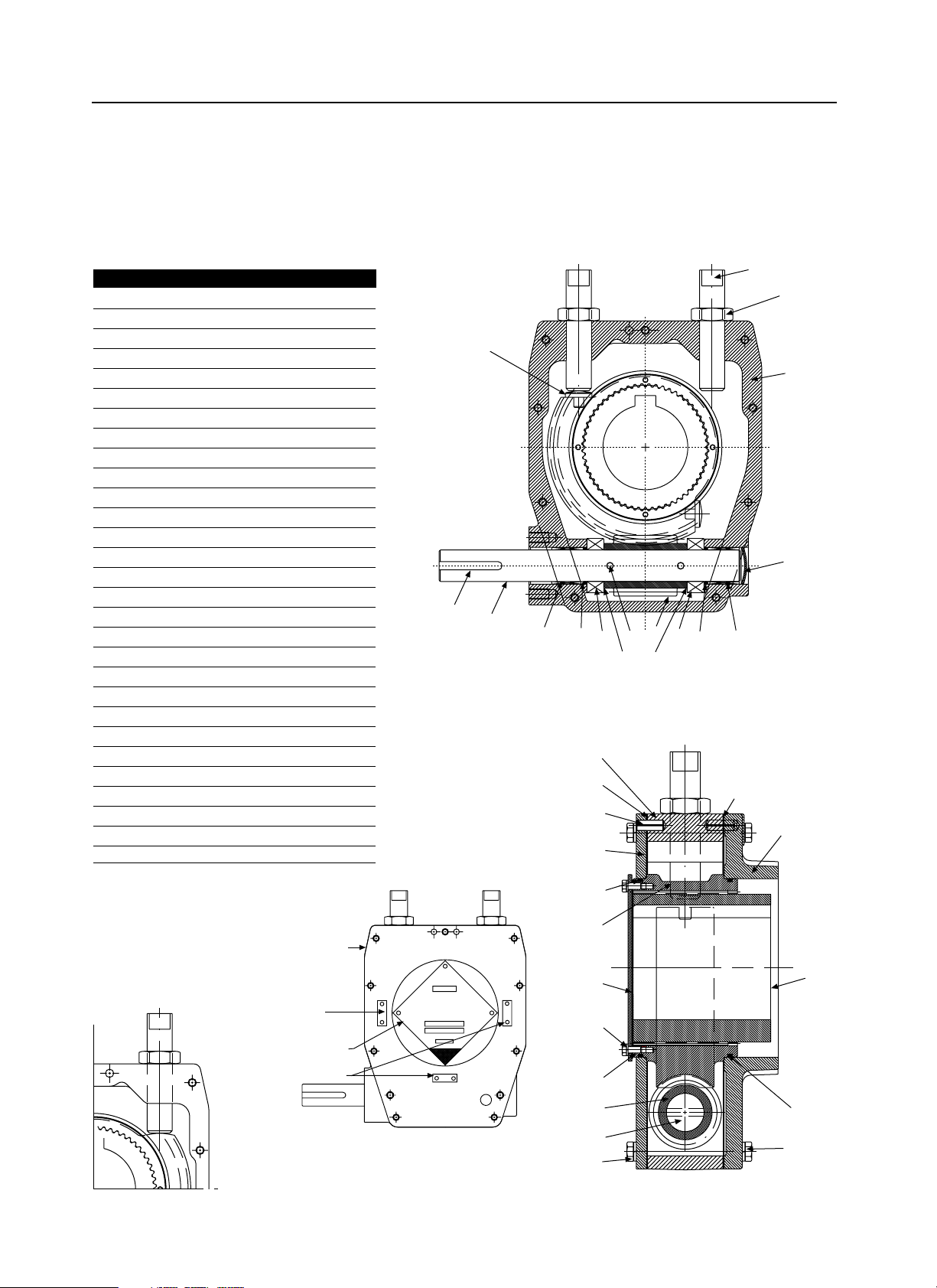
Figure 6.1 (1 of 2) – WTR with SGA parts breakdown (3 through 150)
6-1
Ductile iron
Assembly only
(No stop pins)
Piece Description Quantity
1 WTR Housing 1
2 WTR Housing Base 1
3 WTR Housing Cover 1
4 Drive Sleeve 1
5 Pointer Cap 1
6 Input Shaft 1
7 Worm 1
8 Spiral Pin 2
9 Thrust Bearing 2
10 Bushing 2
11 Key 1
12 Core Plug 1
13 Mechanical Stop Screw 2
14 Jam Nut 2
15 Hex Head Cap Screw A/R
16 Spring Washer A/R
18 Housing Gasket 2
19 Hex Head Cap Screw 4
20 Spring Washer 4
21 O-Ring 2
22 Pointer Gasket 1
23 Dowel Pin 5
24 Splined Adapter 1
25 O-Ring 2
26 Stop Pin (with bronze worm only) 2
28 Shim Washer 2
29 Label Kit 1
30 Nameplate 1
31 Drive Screw 4
15, 16
18
2
25
1
18
23
3
25
4
5
19, 20
22
6
24
15, 16
7
13
14
1
12
10
21
9
8
9
21
10
26
6
28
28
7
Use only with
Bronze gear
11
29
30, 31
Shown assy B (R/H)
Clockwise to close
Limitorque
J
Shut label
Location
Assy A (L/H)
Counter
Clockwise
To close
Page 28
WTR Series
Parts Breakdown
WTR Installation & Maintenance Manual 330-15000 • Revision A • August
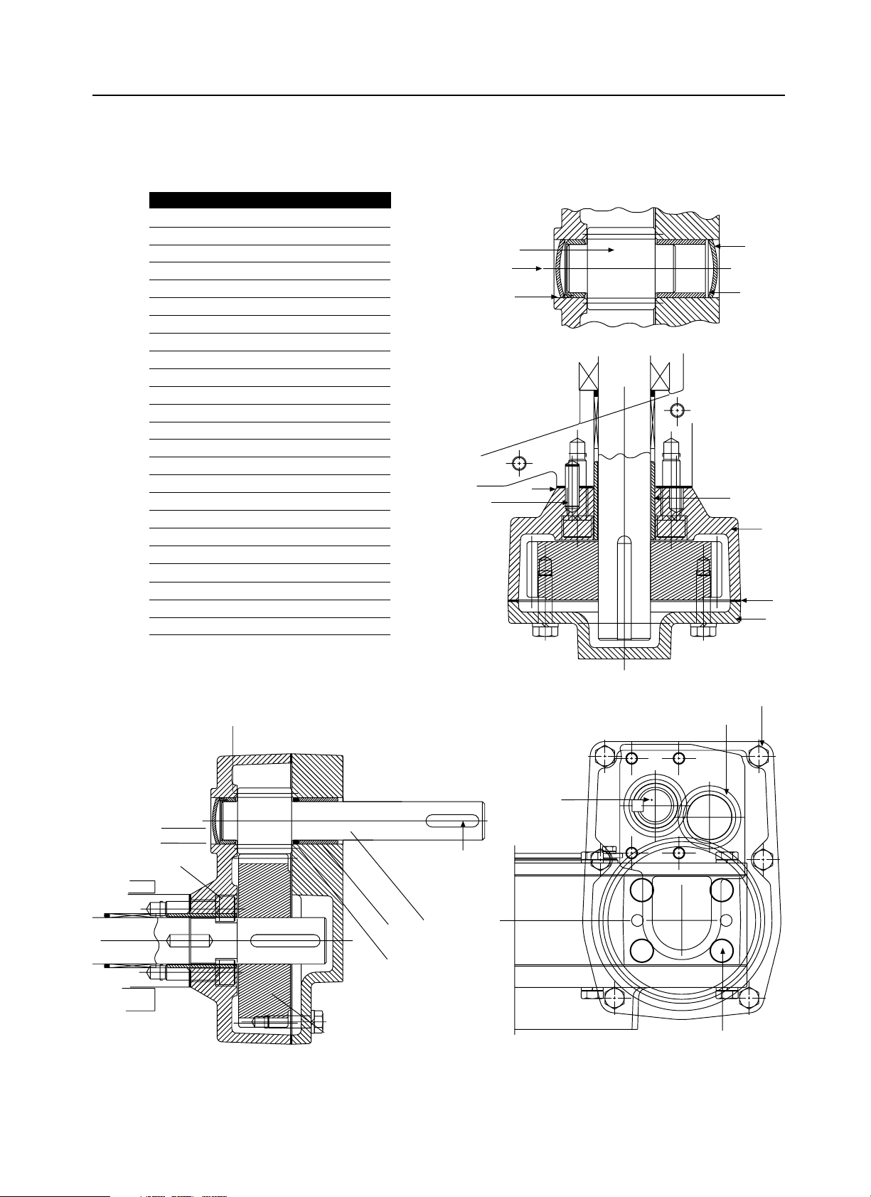
Figure 6.1 (2 of 2) – WTR with SGA parts breakdown (3 through 150)
6-2
Piece Quantity Description
1 1 Spur Gear Housing
2 1 Housing Cover
3 1 Input Shaft & Pinion
4 1 Output Spur Gear
5 1 Idler Gear
6 2 Idler Bushing
7 1 Cover Gasket
8 1 Housing Gasket
9 2 Bushing
10 1 O-Ring
11 6 Hex Head Cap Screw
12 6 Lockwasher
13 4 Socket Head Cap Screw
14 4 Lockwasher
15 1 Key
16 1 Dowel Pin
17 1 Register
18 3 Welsh Plug
19 1 Mounting Adapter
20 4 Lockwasher
21 4 Hex Head Cap Screw
22 4 Hex Head Cap Screw
23 4 Lockwasher
24 1 Bushing
6
18
13, 14
9
10
3
15
4
9
11, 12
13, 14
16
3
5
2
1
17
8
16
7
5
18
6
18
9
Page 29
WTR Series
Parts Breakdown
WTR Installation & Maintenance Manual 330-15000 • Revision A • August
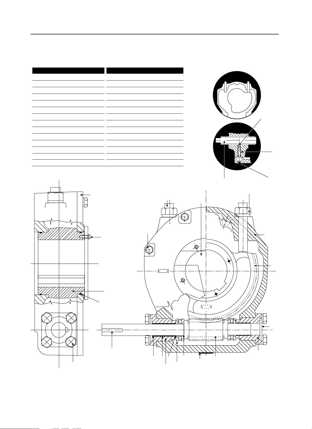
Figure 6.2 (1 of 2) – WTR with SGA parts breakdown (430 through 575)
6-3
Piece Quantity Description
1 1 Housing
2 1 Housing Cover
3 1 Wormshaft
5 1 Drive Sleeve
7 1 Pointer Cap
8 1 Closed Endcap
8A 1 Open Endcap
10 2 Thrust Bearing
11 1 O-Ring
12 2 O-Ring
13 2 Bushing
16 A/R Shims
18* 1 Blanking Plate
20 1 Nameplate
Piece Quantity Description
21 1 Key
22 2 Stop Screw
23*** 2 Hex Nut
23A** 2 Pad
24*** 2 Seal Washer
25 A/R Cap Screw
26 A/R Lockwasher
27 4 Cap Screw
28 4 Lockwasher
29** 2 Setscrew
29B** 2 Plug**
30 8 Cap Screw
31 8 Lockwasher
32**** 1 Splined Adapter
* Only on WTR-430 *** Not on WTR-575
** Only on WTR-575 **** Not Shown
29
23A
29B
22
Side
WTR-575
Stop Arrangement
To p
8A
21
OPEN
SHUT
1
5
23, 24
7
22
25, 26
18*
8
3
16
20
10
11
13A
13
30,31
12
27, 28
2
5
Page 30
WTR Series
Parts Breakdown
WTR Installation & Maintenance Manual 330-15000 • Revision A • August
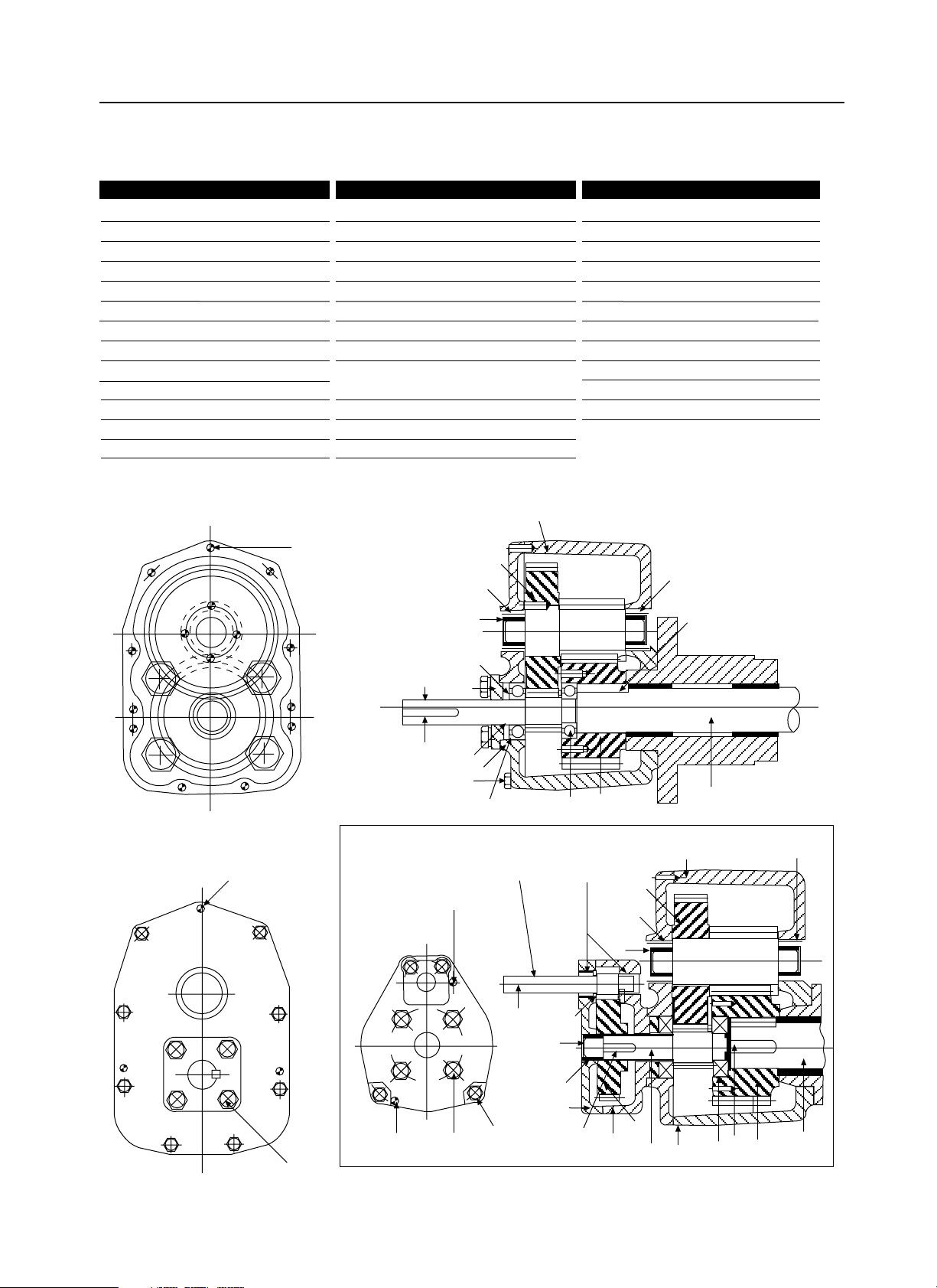
Figure 6.2 (2 of 2) – WTR with SGA parts breakdown (430 through 575)
6-4
Piece Quantity Description
1 1 Housing
2 1 Cover
3 1 Wormshaft
4 1 Output Gear
5 1 Input Gear
6 2 Bearing
6A 1 Bushing
6B 1 Bushing
7* 1 O-Ring
8 1 Packer
9 A/R Dowel Pin
10 2 Core Plug Qu
11 1 Key
Piece Quantity Description
12 A/R Key
13 A/R Lockwasher
13A 4 Lockwasher
14 4 Lockwasher
15 4 Cap Screw
16 A/R Cap Screw
16A 4 Cap Screw
17 1 End Cover
18 1 Intermediate
Gear Sub-Assy
19 A/R Shim
20 1 Housing
21 1 Housing Cover
Piece Quantity Description
22 1 Output Gear
23 1 Input Pinion
24 1 Key
25 2 Bushing
26 1 Bushing
27 1 Plug
28 1 Roll Pin
29 1 Dowel Pin
30 4 Cap Screw
31 4 Lockwasher
32 1 Oil Seal
* WTR-575 Only
9
16A, 13A
28
Double Reduction SGA
19
6
1
6A
12
18
10
17
8
5
11
7
2
13, 16
4
3
6B
27
20
21
22
23
25
32
26
1
6A
18
10
8
5
4
3
6B
12
6
2
11
24
Triple Reduction SGA
28
29
30, 31
14, 15
Page 31

WTR Series
How to Order Parts
WTR Installation & Maintenance Manual 330-15000 • Revision A • August
7 How to Order Parts
To order parts or obtain further information for your Limitorque WTR actuators, contact
your local Limitorque distributor, sales office, or:
Limitorque Corporation
5114 W oodall Road
P.O. Box 11318
Lynchburg, VA 24506-1318
Attn: Parts Department
Phone (804) 528-4400
Fax (804) 845-9736
http://www.limitorque.com
All inquiries or orders must be accompanied by the following information:
1. Unit size
2. Limitorque order number
3. Limitorque serial number
NOTE: Limitorque WTR actuators, under normal operating conditions, are virtually
maintenance-free. No recommended spare parts are suggested by Limitorque.
7-1
Page 32

Page 33

Page 34

Page 35

Page 36

Australian Distributor for Limitorque
Acrodyne Pty Ltd
14/11 Havelock Road
Bayswater, Victoria 3153
Australia
Phone 03-8727-7800
Fax 03-9729-8699
 Loading...