

Page 1
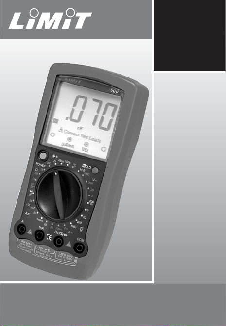
Operating manual
500
Digital Multimeter
Page 2
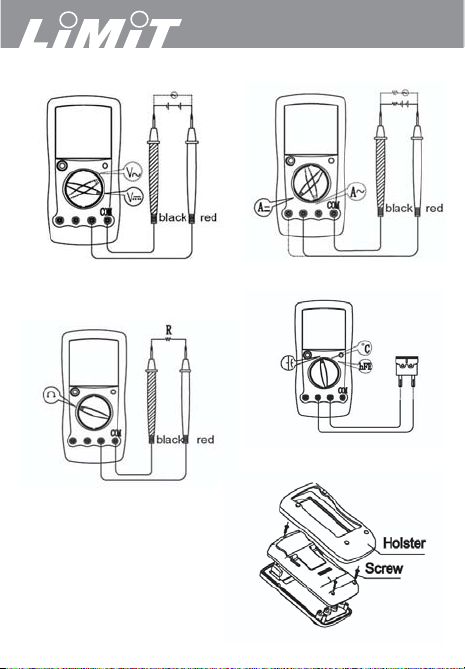
Fig 1. Voltage measurement
DC and AC
Fig 2. Current measurement AC
Fig 3. Diode test
Continuity test
Resistance
Fig 4. Replacing battery
Fig 5. Replacing battery
500
Page 3
Illustrations & Tables
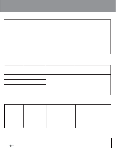
1
DC Voltage
Range Resolution Accuracy Overload
Protection
200mV 0.1mV 250V AC
2V 1mV ±(0,5%+1)
20V 10mV 1000V AC
200V 100mV
1000V 1V ±(0,8%+2)
AC Voltage
Range Resolution Accuracy Overload
Protection
2V 10mV
20V 10V ±(0.8%+3) 1000V AC
200V 100V
1000V 1V ±(1.2%+3)
DC Current
Range Resolution Accuracy Overload
Protection
2mA 1μA ±(0.8%+1) CE Version:Fuse 0.5A,
200mA 0.1mA ±(1.5%+1)
250V, fast type, 5x20mm
20mA 10mA ±(2%+5) Un-Fused
Diodes Test
Range Resolution Overload Protection
1mV 250V AC
Page 4
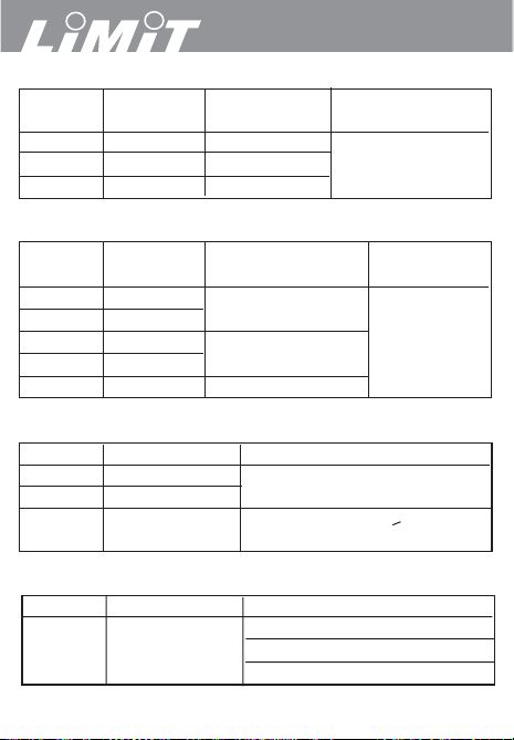
AC Current
Range Resolution Accuracy Overload
Protection
2mA 1μA ±(1.0%+3)
CE Version: Fuse 0.5A,
200mA 0.1mA ±(1.8%+3)
250V, fast type, 5x20mm
20mA 10mA ±(3.0%+5)
Resistance
Range Resolution Accuracy Overload
Protection
200Ω 0.1Ω ±(0.8%+3) + Test Lead
2Ω 1Ω Short Circuit Resistence 250V AC
20kΩ 10Ω ±(0.8%+1)
2kΩ 1kΩ
20MΩ 10MΩ ±(1.0%+2)
Capacitance
Range Resolution Accuracy
2nF 1pF ±(4.0%+3)
200nF 0.1nF
100μF 0.1μF ±(5.0%+4) When it is > 40μF: the
obtained reading is only for reference
Temperature
Range Resolution Accuracy
-40°~0°C ± (3%+3)
°C 1°C 0~400°C ± (1%+3)
400~1000°C ± 2.5%
500
2
Page 5
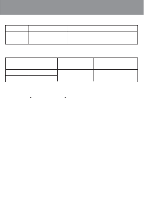
Transistor Test
Range Resolution Accuracy ±(a%reading + b digits)
hFE 1ß Vce≈3V Ibo≈10μA 1000ßMAX
Frequency (UT58C only)
Range Resolution Accuracy Overload
Protection
2kHz 1Hz
20Hz 10Hz ± (1.5%+5) 250V AC
Remarks
• 100mVrms < input amplitude < 30Vrms
3
Tabels
Page 6

500
Language Contents
Language page
English . . . . . . . . . . . . . . . . . . . . . . . . . . . . . . . .5-12
Svenska . . . . . . . . . . . . . . . . . . . . . . . . . . . . . .13-19
Norsk . . . . . . . . . . . . . . . . . . . . . . . . . . . . . . . .20-26
Dansk . . . . . . . . . . . . . . . . . . . . . . . . . . . . . . . .27-34
Suomi . . . . . . . . . . . . . . . . . . . . . . . . . . . . . . . .35-41
Deutsch . . . . . . . . . . . . . . . . . . . . . . . . . . . . . . .42-50
Nederlands . . . . . . . . . . . . . . . . . . . . . . . . . . . .51-58
Français
Italiano . . . . . . . . . . . . . . . . . . . . . . . . . . . . . . .67-74
Español
Português
Polska . . . . . . . . . . . . . . . . . . . . . . . . . . . . . . . .91-98
Eesti . . . . . . . . . . . . . . . . . . . . . . . . . . . . . . . .99-104
Latviski . . . . . . . . . . . . . . . . . . . . . . . . . . . . .105-112
LietuviŠkai . . . . . . . . . . . . . . . . . . . . . . . .
P
yФФНЛМ . . . . . . . . . . . . . . . . . . . . . . . . . . . .121-127
. . . . . . . . . . . . . . . . . . . . . . . . . . . . . .59-66
. . . . . . . . . . . . . . . . . . . . . . . . . . . . . .75-82
. . . . . . . . . . . . . . . . . . . . . . . . . . . .83-90
113-120
4
Page 7

5
English
Overview
General specification
Safety information
Voltage DC and AC
Current DC and AC
Resistance
Temperature
Diodes test
Continuity test
Capacitance
Transistor test
Frequency
Battery
Fuses
Contents
Page 8

Overview
This Operating Manual covers information on safety and cautions.
Please read the relevant information carefully and observe all the
Warnings and Notes strictly.
Limit 500 are 3 1/2 digits instrument for professional use. Display
have large digits and also shows correct test leads terminals and
rotary switch position, makes this instrument easy to handle for the user.
General Specifications
Measuring range and accuracy see page 1-3.
• Fused Protection for VΩmA Input Terminal: 0,5A, 250V fast type,
5x20 mm.
• 20A Terminal: Un-fused.
• Range: Manual ranging
• Maximum Display: Display: 1999 or 31/2 digits.
• Measurement Speed: Updates 2-3 times /second.
• Temperature: Operating: 0°C~40°C (32°F~104°F).
Storage: -10°C~50°C (14°F~122°F).
•
Battery Type: One piece of 9V Battery NEDA 1604 or 6F22 or 006P.
• Safety/Compliances: IEC61010 CAT II 1000V, CAT III 600 V over
voltage and double insulation standard.
• Certification:
Safety Information
This Meter complies with the standards IEC61010: in pollution
degree 2, over voltage category (CAT II 1000V, CAT III 600V) and
double insulation.
Warning
To avoid possible electric shock or personal injury, and to
avoid possible damage to the Meter or to the equipment under
test, adhere to the following rules:
6
500
Page 9

7
English
• Before using the Meter inspect the case. Do not use the Meter if it
is damaged or the case (or part of the case) is removed. Look for
cracks or missing plastics. Pay attention to the insulation around
the connectors.
• Inspect the test leads for damages insulation or exposed metal.
Check the test leads for continuity.
• Do not apply more than the rated voltage, as marked on the
Meter, between the terminals or between any terminal and the
grounding.
• The rotary switch should be placed in the right position and no
any changeover of range shall be made during measurement is
conducted to prevent damage of the Meter.
• When the Meter working at an effective voltage over 60V in DC or
42V rms in AC, special care should be taken for there is danger of
electric shock.
• Do not use or store the Meter in an environment of high tempera-
ture; humidity, explosive, inflammable and strong magnetic fields.
The performance of the Meter may deteriorate after dampened.
•
When using the test leads, keep your fingers behind the finger guards.
• Disconnect circuit power and discharge all high-voltage capacitors
before testing resistance, continuity, diodes and current.
• Before measuring current, check the Meter fuses and turn off
power to circuit before connecting the Meter to the circuit.
• Replace the battery as soon as the battery indicator appears. Whit
to low battery, the Meter might produce false readings that can
lead to electric shock and personal injury.
Functional buttons
Hold • ON/OFF switch.
• ON/OFF for hold function.
Blue • H shows on the display when value is hold.
Page 10

8
500
Voltage measurement DC and AC (see fig 1)
1. Insert the red test lead into the HzVΩ terminal and the black test
lead into the COM terminal.
2. Set the rotary switch to an appropriate measurement position in
V--range for DC or V~ for AC. When the value is unknown always
start from the max range 1000 V.
3. Connect the test leads across with the object being measured.
The measured value shows on the display.
Note
• Displays 1 selected range is overload; it is required to select a
higher range in order to obtain a correct reading.
•
In each range, the Meter has an input impedance of approx.10MΩ.
This loading effect can cause measurement errors in high impe
dance circuits. If the circuit impedance is less than or equal to
10kΩ, the error is negligible (0.1% or less).
Current measurement DC and AC (see fig 2)
Warning
Never attempt an in-circuit current measurement where the voltage
between terminals and ground is greater than 250 V.
If the fuse burns out during measurement, the Meter may be damaged or the operator himself may be hurt. Use proper terminals, function, and range for the measurement.
When the testing leads are connect-ed to the current terminals, do
not parallel them across any circuit.
Measuring time for current should be less than 10 sec and interval
between measurement should be at least 15 minutes.
To measure current, connect as follows:
1.
Turn off power to the circuit. Discharge all high-voltage capacitors.
2. Insert the red test lead into the A or mA terminal and the black
test lead into the COM terminal.
Page 11

9
English
3. Set the rotary switch to an appropriate measurement position A
... range for DC or A~ for AC. When the value is unknown
always start from the max range 20 A.
4. Break the current path to be tested. Connect the red test lead to
the more positive side of the break and the black test lead to the
more negative side of the break.
5. Turn on power to the circuit. The measured value shows on the
display.
Note
• Displays 1 selected range is overload, it is required to select a
higher range in order to obtain a correct reading.
Resistance measurement
1. Insert the red test lead into the HzVΩ terminal and the black test
lead into the COM terminal.
2. Set the rotary switch to an appropriate measurement position in
Ω range.
3. Connect the test leads across with the object being measured.
The measured value shows on the display.
Note
•
The test leads can add 0.1Ω to 0.3Ω of error to resistance measurement. To obtain precision readings in low-resistance measurement, that is the range of 200Ω, short-circuit the input terminals
beforehand and record the reading obtained. This is the additional resistance from the test lead.
Temperature measurement (see fig 4)
1. Insert the multi socket into the mA and HzVΩ terminals.
2. Set the rotary switch to the °C position.
3. Insert the temperature probe to the multi socket.
4. Place the temperature probe to the object being measured.
Page 12

10
The measured value shows on the display.
Note
• The included point contact temperature probe can only be used
up to 230 °C.
•
The temperature function is type K. For measuring higher temperatures other probes of type K can be used.
Diode test (see fig 3)
Use the diode test to check diodes, transistors, and other semiconductor devices. The diode test sends a current through the semiconductor junction, and then measures the voltage drop across the
junction. A good silicon junction drops between 0.5V and 0.8V.
To test a diode out of a circuit, connect as follows:
1. Insert the red test lead into the HzVΩ terminal and the black test
lead into the COM terminal.
2. Set the rotary switch to diode position.
3. For forward voltage drop readings on any semiconductor compo-
nent, place the red test lead on the component’s anode and
place the black test lead on the component’s cathode.
The measured value shows on the display.
Continuity test (See fig 3)
To test for continuity, connect as follows:
1. Insert the red test lead into the HzVΩ terminal and the black test
lead into the COM terminal.
2. Set the rotary switch to continuity position.
3. Connect the test leads across with the object being measured.
The buzzer sounds if the resistance of a circuit under test is less
than 70 Ω.
Capacitance measurement (See fig 4)
500
Page 13

11
1. Insert the multi socket into the mA and HzVΩ terminals.
2.
Set the rotary switch to an appropriate measurement position in F range.
3. Connect the capacitor to be tested into the multi socket. The
measured value shows on the display.
Note
• When 1 displays the capacitor is short-circuit or the selected
range is to low.
•
To minimize the measuring error caused by the distributed capacitor, the testing lead should be short as possible.
Transistor test (See fig 4)
1. Insert the multi socket into the mA and HzVΩ terminals.
2. Set the rotary switch to the hFE position.
3. Connect the NPN or PNP type transistor to be tested into the
multi socket. The measured value shows on the display.
Frequency
1. Insert the red test lead into the HzVΩ terminal and the black test
lead into the COM terminal.
2. Set the rotary switch to an appropriate measurement position in
Hz range.
3. Connect the test leads across with the object being measured.
The measured value shows on the display.
Replacing the Battery (see figure 5)
1. Disconnect the connection between the testing leads and the cir-
cuit under test when battery indicator appears on the display.
2. Turn the Meter to OFF position.
3.
Remove the screw, and separate the case bottom from the case top.
4. Replace the battery with a new 9V battery (NEDA 1604 or 6F22
or 006P).
5. Rejoin the case bottom and case top, and reinstall the screw.
English
Page 14

12
500
Replace the fuse (see figure 5)
1. Disconnect the connection between the testing leads and the cir-
cuit under test.
2. Turn the Meter to OFF position.
3.
Remove the screw and separate the case bottom from the case top.
4. Remove the fuse by gently prying one end loose, and then take
out the fuse from its bracket.
5. Replace only fuses with the identical type and specification as
follows. 0,5A 250V, fast type, 5x20mm.
6. Rejoin the case bottom and case top, and reinstall the screw.
Replacement of the fuses is seldom required. Burning of a fuse
always results from improper operation.
 Loading...