

Page 1

ZL-6250A EElleeccttrroonniicc TThheerrmmoossttaatt
IInnssttrruuccttiioonn MMaannuuaall
1. Feature
ZL-6250A is cooling/heating thermostat, dedicated to control the cold storage, seafood
machine, poultry production, water heaters, etc. Front panel water-proof level is IP65. The
small case size is same as those on the market.
2. Main Function
● Temperature regulation: switch between cooling and heating automatically
● Temperature display
● Temperature calibration
● Output delay protection
● Buzzer alarm output
● External warning input
● Max high-temperature or min low-temperature exceed warning.
● Sensor failure warning
3. Size Specification
1. Front panel dimension: 78* 34.5mm
2. Drilling template: 71* 29mm
3. Whole machines dimension: 78* 34.5* 71mm
4. Length of sensor(s): 3m (including the sensor probe)
4. Technical Specification
● Temperature Sensor: NTC
● Setting Range: -40~120℃
● Display Range: -40~130℃
● Working Temperature: -10~45℃
● Storage Temperature: -30~70℃
● Humidity: 5~85%RH (without dewing)
● Power Supply: AC185~245V, 50HZ
● Terminal Wire: <= 2 * 1.5mm2 or 1 * 2.5mm2
● Load Current: 7A 250Vac(Resistive load)
● Case: PC + ABS Fire Proof
● Protection Degree: IP65 (front panel)
5. Display Indication
Page 2

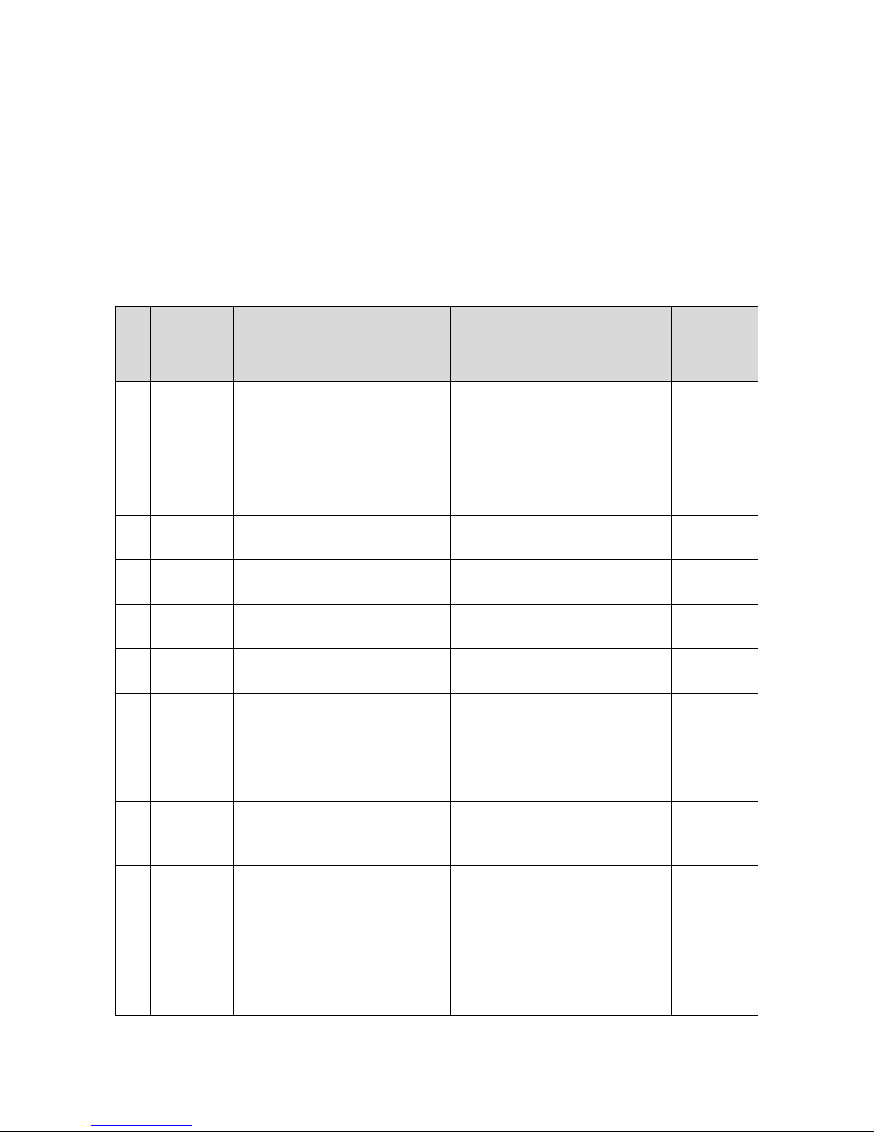
Display Sign Description
Icon Function On Off Blinking
Temp. Set ---- ---- Setting Temp.
Cool Control In cool mode Not in cool mode
Compressor power on delaying
Heat Control In heat mode Not in heat mode
Heat output power on delaying
Repair ---- No fault Be faulty
Warning ---- No warning Be warning
On/Off Offline Online ----
Panel Digit Indication
Four red digits display the measured temperature and warning code.
No. Display Code Warning Information
1 E01
Room temperature sensor fault
( short circuit or open circuit )
2 Hi Temperature exceeds the MAX value
3 Lo Temperature exceeds the MIN value
4 EE Data access error
5 Err Password error
6 iA External warning
7 UnL Restore the default parameters
6. Keypad Operation
6. 1 Set Cool/heating Temperature
Keeping 【S】 pressed for 3 seconds to enter temperature setting mode. The temperature set
indicator is blinking, and the digital shows the set temperature. Press key 【▲】 or 【▼】
to change the set temperature ( Keeping 【▲】 or 【▼】 pressed, it will be adjusted quickly).
Press 【S】, the set temperature will be saved and leave the setting mode. Or do not press any
keys for 30 seconds; the device will leave the set mode without saving the set data.
6. 2 Set System Parameters
Enter Into System Parameter Setting Mode
Use the password to enter into the parameter setting mode, the factory password is “1111”.
Keep 【P】 pressed for 3 seconds to enter the mode. The digital displays 『---0』, then press
【▼】 to the digit of the password, press 【▲】 to the value of the digit(0-9), press 【S】
Page 3
to confirm. If the password is wrong, it will shows 『Err』, and returns to the measuring
temperature states after the buzzer beeping 3 times. If the password is right, the buzzer
beeps once and enters into the mode. Digital will display a parameter code. Press 【▲】 or
【▼】 to select the parameter code. Press 【S】 to show its value. Press 【▲】 or 【▼】
to set the value. Press【S】 to return parameter code display status.
Exit the Mode
Keep depressing 【P】 for 3 seconds, the set parameters will be saved, the mode exits.
If do not press any key for 30 seconds, the mode will exit without saving all the set data.
ZL-6250A:
No
Parameter
code
Function Range Note
Factory
setting
1 U10 Compressor power on delay time
0~100min
3
2 U11 Comp. MIN continuous work time
0~100min
3
3 U15 Heat output power on delay time 0~300s 0
4 U16 Heat output continuous work time 0~300s 0
5 U20
Room temperature sensor
calibration
-9.9~+9.9
0
6 U22 Temperature difference
0.1~+10.0℃
The hysteresis
of control
1.0
7 U52
Over-temperature warning delay
time
1~180min
30
8 U53
First over-temperature warning
delay time after power supply
0~180 hour 0: Disable 2
9 U54
High-temperature warning
deviation value to Max Temp
Temperature
difference~60 ;℃
OFF
OFF(>60.0℃):
Disable
OFF
10
U55
Low-temperature warning
deviation value to Min Temp
Temperature
difference~60 ;℃
OFF
OFF(>60.0℃):
Disable
OFF
11
U60 External input warning mode 0~4
0:Warning off
1:On, Lock
2:On, Unlock
3:Off, Lock
4:Off, Unlock
0
12
U61
External warning input delay
0~120min 0
Page 4
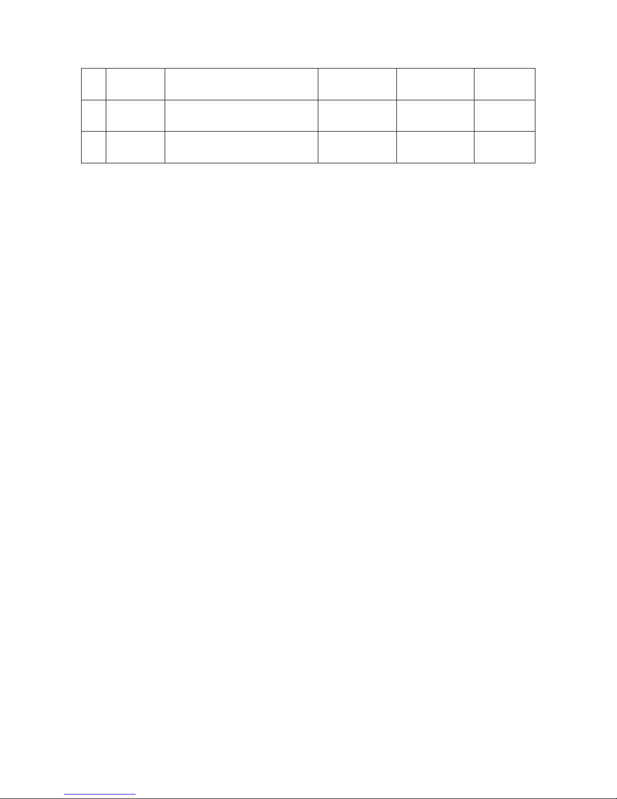
13
U62 Buzzer warning 0~1
0:Warning off
1:Warning on
0
14
U91 On/Off 0~1
0:Disable
1:Enable
0
15
U99 Password 0000~9999 1111
7. Control Function Description
7.1 Cool Control Instruction
7.1.1 Cool control
● When the temperature “Set temperature”+”U22”, and the ≧ compressor has stopped for
“U10”, the compressor starts.
● When the temperature “Set temperature”≦ -”U22”, and the compressor has run for “U11”,
the compressor stops.
7.1.2 Compressor delay protection
● After power supply, the compressor is able to start only after the time (U10) has passed.
● After the compressor stops, it is able to restart again only after the time (U10) has passed.
● After the compressor starts, it is able to stop only after the time (U11) has passed.
7.2 Heat Control Instruction
7.2.1 Heat control
● When the temperature “Set temperature”≦ -”U22”, and the heat output has run for “U10”,
the heat output starts.
● When the temperature “Set temperature”+”U22”, and the ≧ heat output has stopped for
“U11”, the heat output stops.
7.2.2 Heat output delay protection
● After power supply, the heat output is able to start only after the time (U10) has passed.
● After the heat output stops, it is able to restart again only after the time (U10) has passed.
● After the heat output starts, it is able to stop only after the time (U11) has passed.
7.3 On/Off line function
◇If U91 is set to 1, the thermostat works in “On/Off line mode”.
When offline, depress 〖▼〗for 3 seconds, it will switch to online, and start to regulate temp.
When online, depress 〖▼〗for 3 seconds, it will switch to offline, and stop to regulate temp.
The thermostat has auto restart function.
If U91 ◇ is set to 0, the thermostat will always regulate the temp. after power supplied.
7.4 Buzzer Function
Buzzer sounds shortly for every key press. When confirming the parameter setting, it sounds
longer. 3 short beeps means invalid. When the system comes wrong or external alarm input,
the buzzer alarm function will be off if U62=0, or the buzzer continuous alarming if U62=1.
After the system problem solved and disappears, press 【P】 key to stop warning.
Page 5
7.5 High-temperature and Low-temperature Warning
● When the room temperature ≥ “set temperature”+ “U54”, and the time reaches to “U52 or
U53”, high temperature warning starts.
● When the test temperature ≦ “set temperature”+ “U55”, and the time reaches to “U52 or
U53”, low temperature warning starts.
Note: High/low temperature warning has no influence in the state of defrost output and
control output.
7.6 External Input Warning
There are following ways for the external warning input, when the condition meets, the
device will warn:
Normal On: If close, warning starts.
Normal Off: If open, warning starts.
Lock: when the external warning input signal disappears, system keeps warning, until
pressing the【P】key to stop the warning.
Unlock: when the external warning input signal disappears, warning stops.
Note: When external warning starts, output control will be emergent closed.
7.7 Temperature Calibration Function
When there is tolerance between the measured temperature and real temperature, set
parameter U20 to calibrate. The calibration range is ±9.9℃. When setting the parameter, the
step is 0.1℃ for every key press. Keep the key pressed, the set data will increase/decrease
continuously and quickly.
7. 8 Restoring the Default Parameters and Password
Keep【P】and 【▲】keys pressed for 5 seconds, buzzer sounds and the device displays “UnL”,
press【▼ 】 twice, buzzer sounds, system auto restores the default parameters and
password“1111”.
8. Controller Installation
8.1 Warning
Avoid installing the device in the following environment:
● Relative humidity is greater than 90%, or possibly dewing.
● Strong vibration.
● Possibility be dropped, or within fog.
● Exposed to eroding and polluting gases (such as: air containing sulfur and ammonia, salty
fog, smoky mist) to prevent erosion and oxidation.
● Ambient containing explosive or inflammable materials/gases.
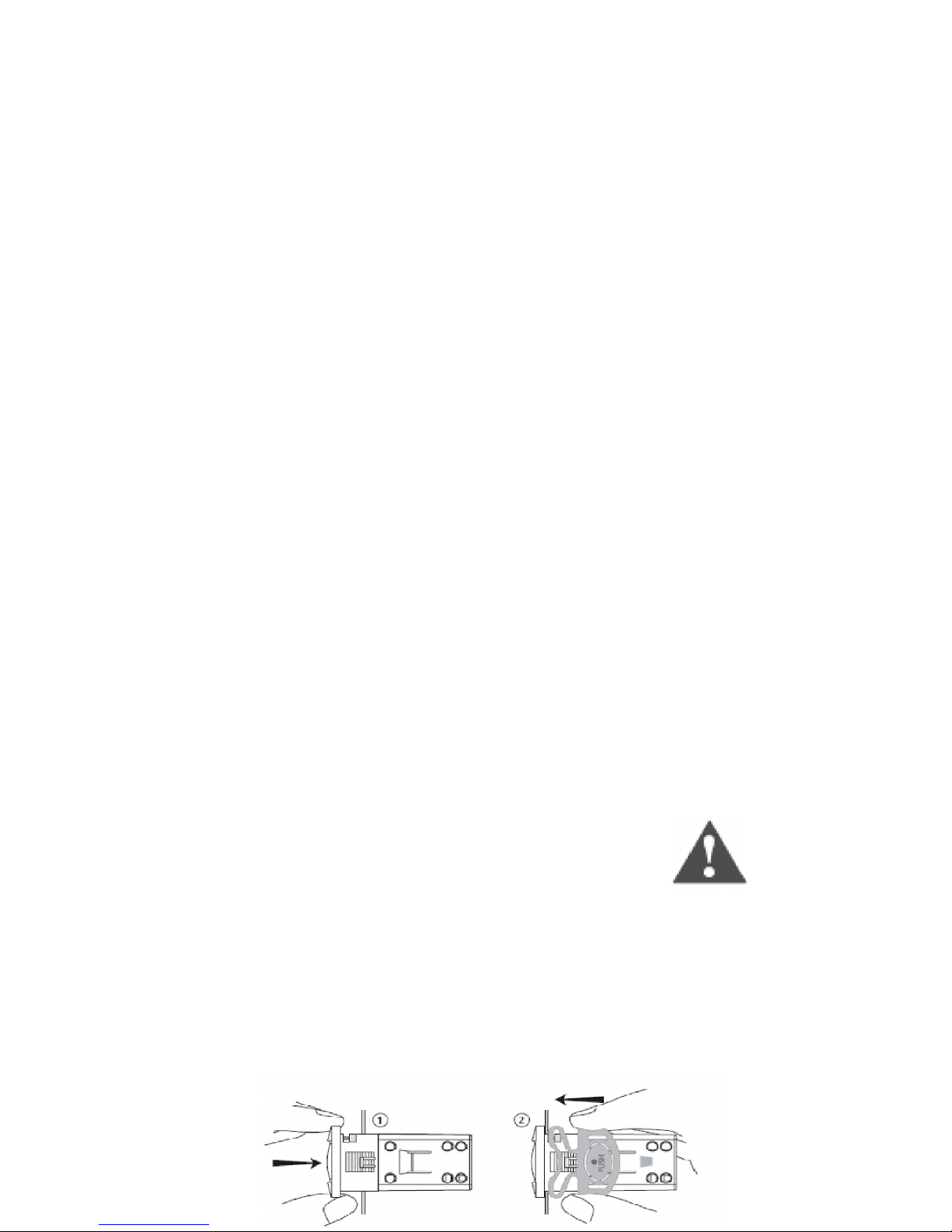
8.2 Installation Procedure
Insert the controller into hole (step one) Slide the bracket to fix the device (step two)
Page 6
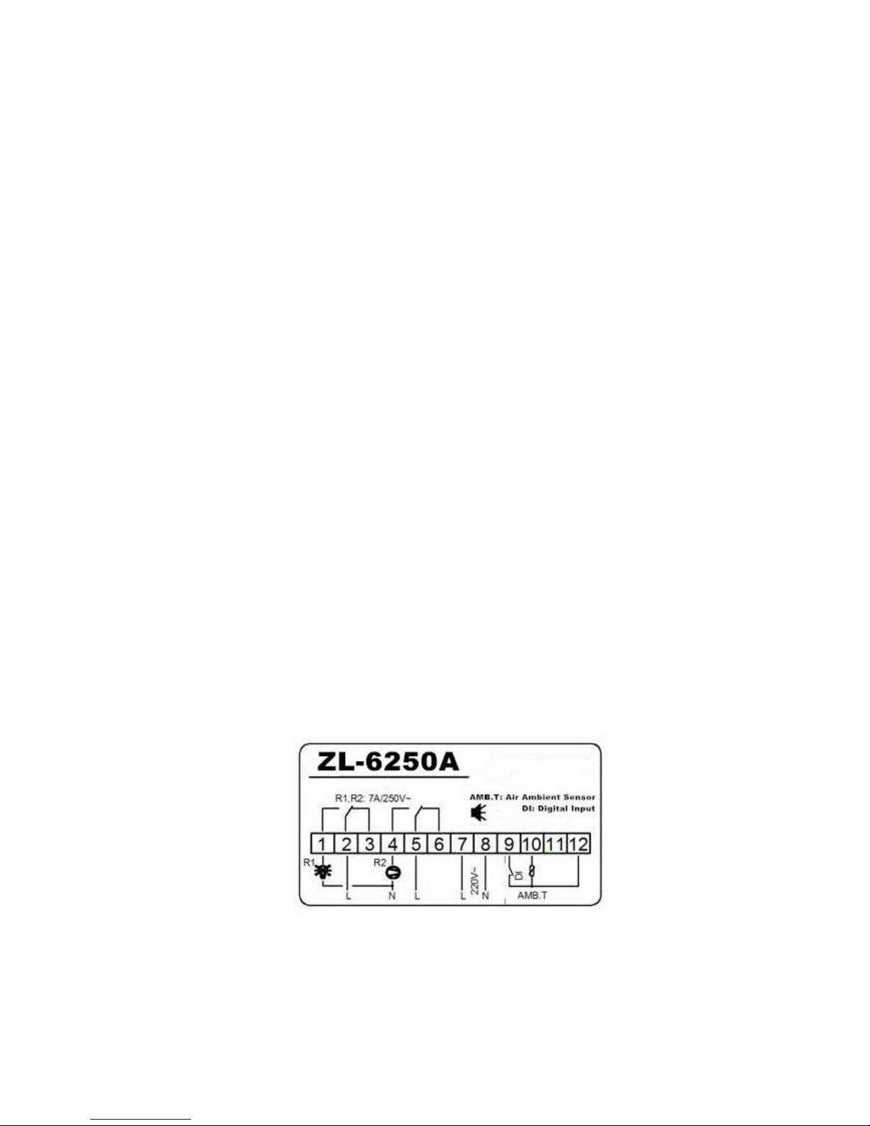
9. Electrical Connection
Warning
● Electrical wiring must be manipulated by certified electrician.
● Wrong power supply may damage the device and system seriously.
● Try with effort to layout the sensors and switches line apart from inductive load lines and
power supply lines. The sensors and switches lines are not allowed go with the power supply
lines and inductive load lines in a same pipeline, and are not allowed to pass near the
contactor, breaker and the similar.
● Reduce the length of sensors’ wiring as possible, avoid forming a spiral shape near the
power devices.
● Avoid direct contact with the internal electronic components.
● After finish and check the electrical wiring layout, before connect them to the device,
please follow this instruction: Pay attention the “electrical wiring diagram” below, wrong
connection possibly damages the device and the system, and may be dangerous to the user.
All security and protecting device for the equipments are necessary. They are very important
to protect the equipments, and the user’s safety.
Electrical wiring diagram:
 Loading...