

Page 1
Suzhou Lily Tech. Co., Ltd.
www.suzhoulily.com.cn/en Page 1, Total 2 Pages
ZL-6200A Temperature Controller
Instruction Manual A1.0
Introduction
ZL-6200A is for cooling, heating or warning control. Front panel water proof level IP65, control resolution 0.1℃, keypad password
protection. It is suitable to control or audit cold storage, aquarium, water heater, and so on.
Main Function
Cooling, heating or auditing
Over temperature warning
Sensor failure warning
Temperature control
Temp. output energized/de-energized periodically when
sensor fails
Specification
Power supply: 185 ~ 245Vac, 50/60Hz
Sensor: NTC, 1.5 meters long
Display range: -50 ~ 120℃
Setting range: -50 ~ 120℃
Resolution: 0.1℃
Absolute accuracy: 1% at 25℃
Accuracy after calibration: 0.1℃
Temp. output, R1: 7A, 250Vac (pure resistance load)
Warning: Buzzing
(When in warning mode, temp. output as warning output)
Working: -10 ~ 45℃, 5 ~ 90%RH without dew
Dimension: W78 x H34.5 x D71 (mm)
Installation drilling: W71 x H29 (mm)
Case materials: PC + ABS fire proof
Protection level: IP65 (Front side only)
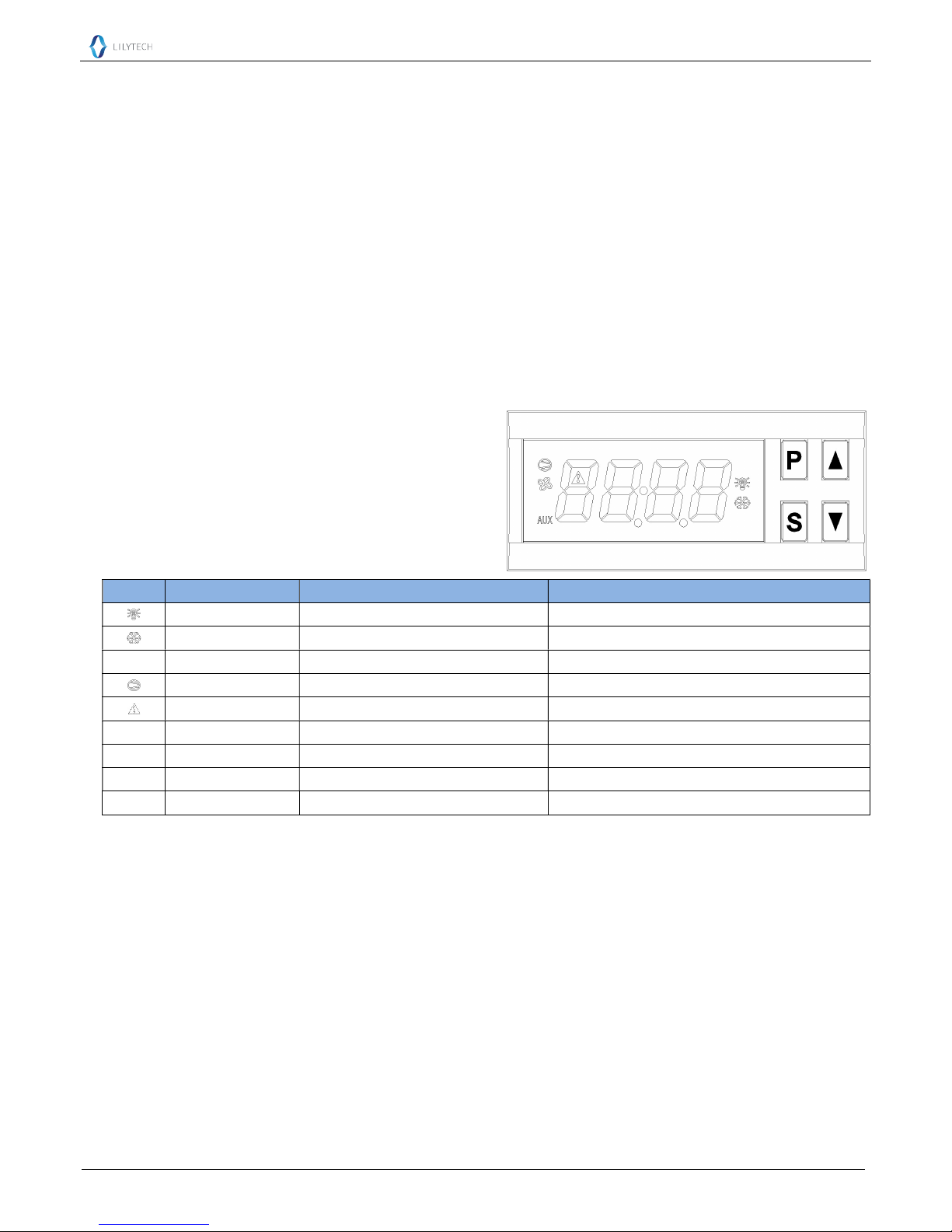
Keypad and Display
Display
Function On Blinking
Heating mode Heating mode Setting set-point
Cooling mode Cooling mode Setting set-point
AUX Warning mode Warning mode Setting set-point
Temp. output, R1 R1 energized Delay protecting
Warning ---- Warning
E1 Warning ---- Sensor open
E2 Warning ---- Sensor short
HH Warning ---- Over high temperature limit
LL Warning ---- Bellow low temperature limit
Operation
On/off: Keep〖S〗depressed for 3 seconds to switch on/off.
Check settings: Press〖▲〗 to check the set-point; Press〖▼〗 to check the hysteresis.
Set Set-Point
Keep〖S〗depressed for 3 seconds to enter into the set status. The current set-point value displays.
Press〖▲〗or〖▼〗 to set the value (keeping depressed can fast set).
Keep〖S〗depressed for 3 seconds to exit, and save the settings.
The status will exit, and the setting will be saved, if no key operation within 30 seconds.
Set System Parameters
Keep〖P〗depressed for 3 seconds: If the password is not “0000”, digits show “---0”, else enter into parameter setting status.
Press〖▼〗to select the digit of the password, press〖▲〗to set the value of the digit.
Press〖S〗 to confirm:
If the password is correct, enter into the parameter setting status, else exit.
Set in parameter setting status:
Press〖▲〗or〖▼〗to select the parameter code (see parameter code table below).
Press〖S〗 to display the value of the code.
Page 2

Suzhou Lily Tech. Co., Ltd.
www.suzhoulily.com.cn/en Page 2, Total 2 Pages
Press〖▲〗or〖▼〗to set the value.
Press〖S〗to return to parameter code selection.
Keep〖P〗depressed for 3 seconds to exit, and save the settings.
The status will exit, and the settings will be saved, if no key operation for 30 seconds.
Parameter Code Table
Code
Function Range Remark Factory set
F0 Hysteresis
0.1 ~ 15.0℃
3.0
F1 Minimum time for R1 to keep de-energized 0 ~ 9 minute 3
F2 Up limit for set-point
-50.0℃~ 120.0℃
-20.0℃
F3 Low limit for set-point
-50.0℃~ 120.0℃
20.0℃
F4 Working mode 1 ~ 3 1: cooling; 2: heating; 3: warning 1
F5 Sensor calibration
-5.0 ~ +5.0℃
0.0℃
F6 Password 0000 ~ 9999 0000: disable password 0000
Control
Cooling Control (F4 = 1)
If Troom ≥ Set-point + F0, and R1 has been de-energized for F1, then R1 energized;
If Troom ≤ Set-point, then R1 de-energized.
Protecting Run When Sensor Fails: R1 will be energized for 15 minutes, and de-energized for 15 minutes, periodically.
Heating Control (F4 = 2)
If Troom ≤ Set-point, and R1 has been de-energized for F1, then R1 energized;
If Troom ≥ Set-point + F0, then R1 de-energized.
Warning Control (F4 = 3)
If Troom ≥ Set-point + F0, or Troom ≤ Set-point, and R1 has been de-energized for F1, then R1 energized;
Temp. Output Load Delay Protection
After power supplied, R1 could be energized after F1 time;
After R1 de-energized, it could be energized again after F1.
Installation
1st: Insert into drilling hole; 2nd: Clamp
Attention
Wiring work should be manipulated by certified technicians.
Wrong connection could damage the controller, and the loads. Power supply to terminal 7 and 8 to check the controller. If there is a
multimeter, check the outputs, as well as input, by the help of settings.
Sensor and input signal wires should not be laid together with power supply wire, and even in same pipe.
Sensor wire is better as short as possible. Not wind the redundant length wire to electrical noise equipment.
The loads should be within the specification of the controller output driving ability. If using ac/dc module as load, or tungsten lamp,
or motor, following the below requirements to avoid surging current damaging or shorten the life time of the controller outputs:
For ac/dc module as load, the rated current should be no more 1/10th of output specification under pure resistance.
For tungsten lamp as load, the rated current should be no more 1/15th of output specification under pure resistance.
For motor, the rate current should be no more 1/5th of output specification under pure resistance.
For example: if drive a 1500W tungsten lamp with 7A
(pure resistance spec.) relay, the relay contactor will
be burnt immediately.
Don’t touch inside components;
Avoid installing controller in the following
environment:
More wet than 90%RH, or easily dew; Vibrating, or will
be shocked; Possible sprayed; Under erosive air; Under
explosive air.
Electrical Wiring
 Loading...