

Page 1
Suzhou Lily Tech. Co., Ltd.
ZL-6290A (ZL-1000) Temperature Controller
Instruction Manual A1.3
Introduction
ZL-6290A (ZL-1000) has two outputs, one for cooling, one for heating, to regulate temperature to a set-point.
It will judge heating or cooling mode automatically.
Main Specification
Sensor: NTC
R
= 10K, B
25
℃
Setting range: -50.0 ~ 99.0℃, or -58.0 ~ 210.2℉
Display range: -50.0 ~ 99.9℃, or -58.0 ~ 211.8℉
Terminal: 2*1.5mm2 or 1*2.5mm2
Outputs: 10A * 2, 250Vac (under pure resistance load)
25/85
= 3435K; R
℃
25
= 5K, B
℃
25/50
= 3470K
℃
Working: -10~45℃, 5~85%RH without dew
Case materials: PC + ABS fire proof
Protection level: IP65 (Front side only)
Dimension: W78 x H34.5 x D71 (mm)
Installation drilling: W71 x H29 (mm)
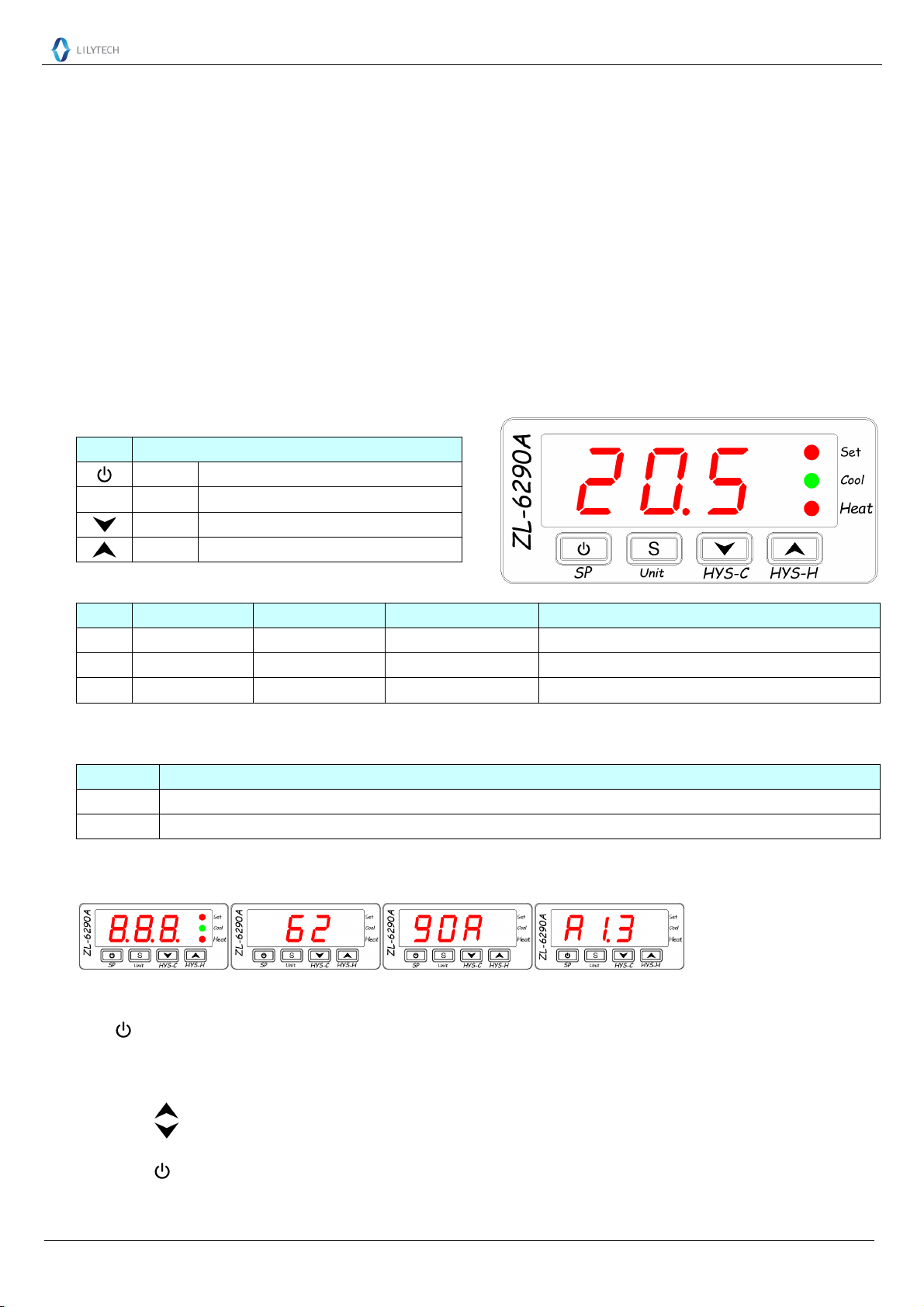
Keypad and Display
Key
Key
S
On/off Fast check Set-point
Set Fast check Temperature Unit
Down Fast check Hysteresis for Cooling
Up Fast check Hysteresis for Heating
Function
LED lamp
LED
Set
Cool
Heat
Function On Off Blinking
Set parameter Setting status
Display fast check result
SP, Unit, Hysteresis
(
Cooling R1 is energized R1 is de-energized Delay protection for R1 (keep de-energized)
Heating R2 is energized R2 is de-energized
LED digit
Display the information, 2Hz blinking.
Warning
Remark
E1 Sensor failure (Short or open)
HH
Power up (reset) display
Display the following information consecutively: all LED units, model name, software version
Temperature over the sensing up limit (
99.9℃ or 211.8℉)
Operation
On/off line
Keep key depressed for 5 seconds to switch online/offline.
Fast check parameters
When not in parameter setting status:
Short press to display heating hysteresis (HYS-H) for 2 seconds, and the Set LED blinks in 2 Hz.
Short press to display cooling hysteresis (HYS-C) for 2 seconds, and the Set LED blinks in 2 Hz.
S
Short press “
Short press to display set-point (SP) for 2 seconds, and the Set LED blinks in 2 Hz.
” key to display temperature Unit (Fahrenheit or Celsius) for 2 seconds, and the Set LED blinks in 2 Hz.
)
Page 1, Total 3 Pages
Page 2
Suzhou Lily Tech. Co., Ltd.
Set parameters
Keep “S” key depressed for 5 seconds to enter into set status: Set LED is on, and the 1st parameter code displayed.
Press or to select parameter. Press “S” key to show the value of the parameter.
Press or to set the value of the parameter. Keeping up/down key depressed can fast set *.
After all are set, keep “S” depressed for 3 seconds to save the settings, and exit the set status.
The set status will exit, and the settings will not be saved, if no key operation for 30 seconds.
Celsius parameter table
Code
F1 Set point
F2 Heating hysteresis (
F3 Cooling hysteresis (
F4 Protection time for cooling
F5 Sensor calibration
Celsius / Fahrenheit (
CF
SE Sensor Selection
Function Range Default
(SP)
HYS-H)
HYS-C)
-50.0 ~ 99.0℃ 10.0℃ * Resolution is 0.1℃
0.1 ~ 15.0℃ 1.0℃
0.1 ~ 15.0℃ 1.0℃
0 ~ 10 min 3 min After power supplied, there is protection time
-9.0 ~ 9.9℃ 0.0℃ * Resolution is 0.1℃
Unit
)
C/F C C: Celsius, F: Fahrenheit
10/5 10
“10”: R
“ 5”: R
= 10K ohm, B
25
℃
= 5K ohm, B
25
℃
25/85
25/50
Remark
= 3435K
℃
= 3470K
℃
Fahrenheit parameter table
Code
SP Set point
dH Heating hysteresis (
dC Cooling hysteresis (
Function Range Default
(SP)
HYS-H)
HYS-C)
-58.0 ~ 210.2
0.2 ~ 27℉ 1.8℉
0.2 ~ 27℉ 1.8℉
℉
50.0
Resolution is 0.1℉
*
℉
Remark
Pt Protection time for cooling 0 ~ 10 min 3 min After power supplied, there is protection time
CA Sensor calibration
CF Celsius / Fahrenheit (
Unit)
-17.8 ~ 17.8
C/F C
SE Sensor Selection 10/5 10
0.0℉ * Resolution is 0.1℉
℉
C: Celsius, F: Fahrenheit
“10”: R
“ 5”: R
= 10K ohm, B
25
℃
= 5K ohm, B
25
℃
25/50
25/85
℃
= 3435K
℃
= 3470K
*: During parameter setting, or fast checking temperature Unit, If the value is bigger than 99.9, or less than -9.9, the 1/10th digit and
temperature Unit will be displayed.
Examples:
-49.2℉, display as “9.2F”. Keep display for 2 seconds, then display “-49.” if the key released;
-10.1℉, display as “0.1F”. Keep display for 2 seconds, then display “-10.” if the key released;
-10.0℉, display as “0.0F”. Keep display for 2 seconds, then display “-10.” if the key released;
-9.9℉, display as “-9.9”;
99.9℉, display as “99.9”;
100.0℉, display as “0.0F”. Keep display for 2 seconds, then display “100.” if the key released;
100.1℉, display as “0.1F”. Keep display for 2 seconds, then display “100.” if the key released;
123.9℉, display as “3.9F”. Keep display for 2 seconds, then display “123.” if the key released;
124.0℉, display as “4.0F”. Keep display for 2 seconds, then display “124.” if the key released.
Control
The controller will judge heating and cooling automatically.
If Troom ≥ Set-point (SP) + HYS-C, and R1 has been de-energized for protection time, then R1 energized. Cool LED is on.
During protection time, R1 keeps de-energized, and the Cool LED is blinking.
If If Troom ≤ Set-point (SP), R1 is de-energized, and the Cool LED is off.
If Troom ≤ Set-point (SP) – HYS-H, then R2 energized. Heat LED is on.
If Troom ≥ Set-point (SP), R2 is de-energized, and the Heat LED is off.
Page 2, Total 3 Pages
Page 3
Suzhou Lily Tech. Co., Ltd.
Sensor Failure
When the sensor fails, the display will show “E1” in 2Hz, and the outputs will be de-energized.
Over temperature
When Troom ≥ 100℃ or 211.9℉, the display will show “HH” in 2Hz.
When the Troom falls below the 100℃ or 211.9℉, restore to normal display.
Restore to Default Settings
Keep the “S” and depressed simultaneously for 5 seconds. Display “UnL”.
Press 2 times.
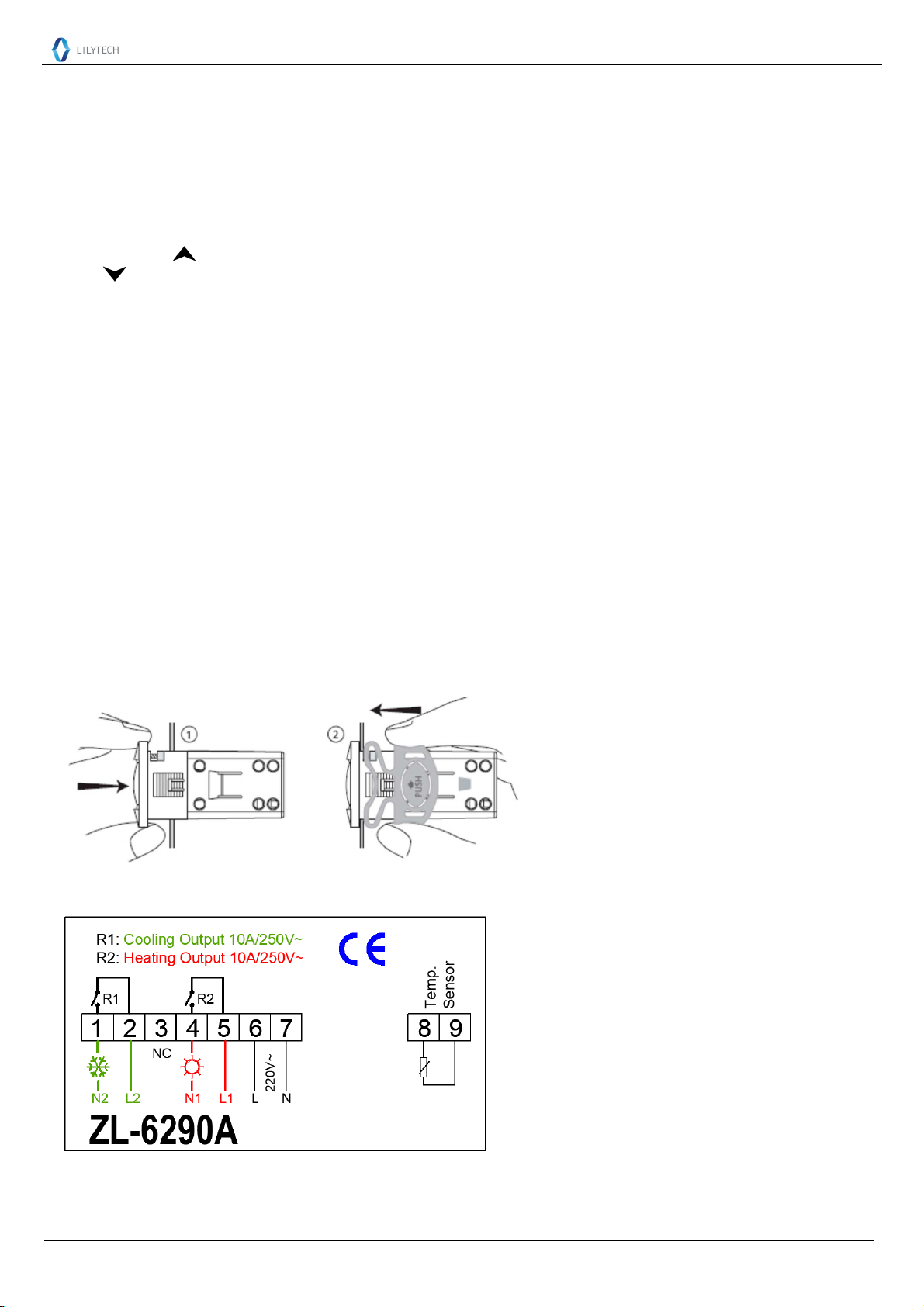
Installation
Attention
Wiring work should be manipulated by certified technicians.
Wrong connection could damage the controller, and the loads. Power supply to terminal 7 and 8 to check the controller. If there is a
multimeter, check the outputs, as well as input, by the help of settings.
Sensor and input signal wires should not be laid together with power supply wire, and even in same pipe.
Sensor wire is better as short as possible. Not wind the redundant length wire to electrical noise equipment.
The loads should be within the specification of the controller output driving ability. If using ac/dc module as load, or tungsten lamp,
or motor, following the below requirements to avoid surging current damaging or shorten the life time of the controller outputs:
For ac/dc module as load, the rated current should be no more 1/10th of output specification under pure resistance.
For tungsten lamp as load, the rated current should be no more 1/15th of output specification under pure resistance.
For motor, the rate current should be no more 1/5th of output specification under pure resistance.
For example: if drive a 1500W tungsten lamp with 7A (pure resistance spec.) relay, the relay contactor will be burnt immediately.
Don’t touch inside components;
Avoid installing controller in the following environment:
More wet than 90%RH, or easily dew; Vibrating, or will be shocked; Possible sprayed; Under erosive air; Under explosive air.
Step
1st: Insert into drilling hole 2nd: Clamp
Electrical Wiring
Page 3, Total 3 Pages
 Loading...