

Page 1
Page 2
1
1
Contents
Important Safety Instructions: ........................................................................................... 2
Precaution: ........................................................................................................................ 2
1. Main Features ............................................................................................................... 3
2. Production Description .................................................................................................. 4
2.1 Front Panel ................................................................................................................ 4
2.2 Rear Panel .................................................................................................................. 5
3. Menu Setting ................................................................................................................. 8
3.1 Shortcut keys ............................................................................................................. 8
3.2 MENU Operations ...................................................................................................... 9
4. Product Parameters ..................................................................................................... 26
5. Accessories .................................................................................................................. 26
6. Trouble Shooting ......................................................................................................... 27
Appendix 1: 3D LUT Loading ............................................................................................ 28
Appendix 2: Remote Terminal Instructions ...................................................................... 30
Page 3
2
2
Important Safety Instructions:
Please read User Guide before using this product.
Please keep User Guide for future reference.
Please read the precaution to prevent possible danger and loss of property.
Precaution:
Please do not place the display screen towards the ground.
Please avoid heavy impact or drop onto the ground.
Please do not use chemical solutions to clean this product. Please wipe with a clean soft cloth to
maintain the brightness of the surface.
Please do not block any vent hole.
Please follow the instructions and trouble-shootings to adjust the product. Other improper adjustment
may result in damage. Any further adjustment must be performed or conducted by a qualified technician.
Please unplug the power and remove the battery if long-term no-use, or thunder weather.
Page 4
3
3
1. Main Features
Support standard 12G-SDI input interface (x4), and support Single-Link, Dual-Link and Quad-Link signals.
Support HDMI 2.0/ 1.4 inputs and loop outputs.
Support SFP input, optical module for optional.
Support Quad Split Multiview
Input & loop out Quad-Link signals support up to 7680x4320 60, 59.94, 50, 48, 47.95, 30, 29.97, 25, 24,
23.98p and 8192x4320 60, 59.94, 50, 48, 47.95, 30,29.97, 25,24, 23.98p.
Input & loop out Single-Link support up to 3840x2160 60, 59.94, 50, 48, 47.95, 30, 29.97, 25, 24, 23.98p
and 4096x2160 60, 59.94, 50, 48, 47.95, 30, 29.97, 25, 24, 23.98p.
12 bits data processing and 12 bits data buffering
Monitor control via GPI/ RS422/ LAN.
Customized Menu Knob.
Support customized various waveform mode: Waveform/ Vector/ Histogram/ Audio Vector/ Level Meter.
HDR (High Dynamic Range) display supporting ST 2084/ Hybrid Log Gamma.
Gamma selection: 1.8-2.8.
Custom 3D LUT file load through USB.
The Color Gamut can support up to SMPTE-C/ Rec709/ EBU/ DCI-P3/ BT2020.
Color Space/ HDR/Gamma / Camera Log comparison with original (side by side).
Color Temperature: 3200K/ 5500K/ 6500K/ 7500K/ 9300K/ User.
False Color: Default/ Spectrum/ ARRI/ RED.
Aspect Marker (16:9/ 1.85:1/ 2.35:1/ 4:3/ 3:2/ 2.0X/ 2.0X MAG/ Grid/ User).
Aspect (Full/ 16:9/ 1.85:1/ 2.35:1/ 4:3/ 3:2/ 2.0X/ 2.0X MAG).
Audio: supporting Audio Vector, Level Meter, (HDMI supporting 8 channels / SDI supporting 16 channels).
Time Code: LTC/ VITC.
UMD display: White/ Red/ Green/ Blue/ Yellow/ Cyan/ Magenta text color for optional.
Color Bar Mode: Rec601/ Rec709/ BT2020.
Check Field: Red/ Green/ Blue/ Mono.
Zoom at any position and at different scale.
Peaking (Red/ Green/ Blue/ White/ Black).
Tally (Red/ Green/ Yellow).
Page 5
4
4
2. Production Description
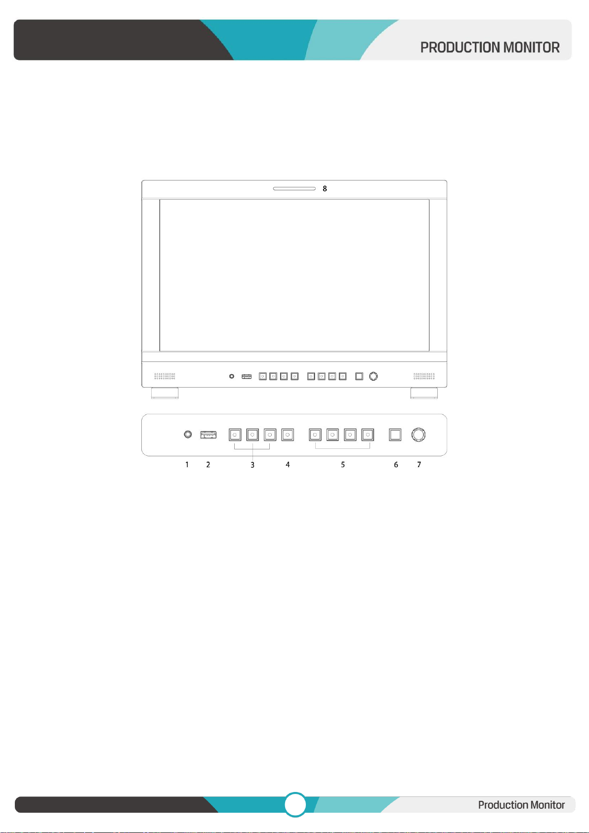
2.1 Front Panel
1) Earphone Jack
2) USB (For 3D LUT load and software update)
3) SDI Buttons
- Single Button/ Lamp: SDI1/ SDI2/ SDI3/ SDI4/ SFP signal input.
-MV1 Input Button (Quad Mode): SDI1/SDI2/SDI3/SDI4/SFP/HDMI signal input.
- 2SI Button/ Lamp
-MV2 Input Button (Quad Mode):SDI1/SDI2/SDI3/SDI4/SFP/HDMI signal input.
- Square Button/ Lamp
-MV3 Input Button (Quad Mode):SDI1/SDI2/SDI3/SDI4/SFP/HDMI signal input
4) HDMI Button/ Lamp
-MV4 Input Button (Quad Mode):SDI1/SDI2/SDI3/SDI4/SFP/HDMI signal input
5) F1/ F2/ F3/ F4 Button and Lamp
Assigned function by factory as follow:
Page 6

5
5
- [F1]: Peaking - [F3]: Waveform
- [F2]: Level Meter - [F4]: Color Space
6) Exit Button
Under Quad Mode: Display the signal input status
7) Menu Knob
8) TALLY (indicator light)
2.2 Rear Panel
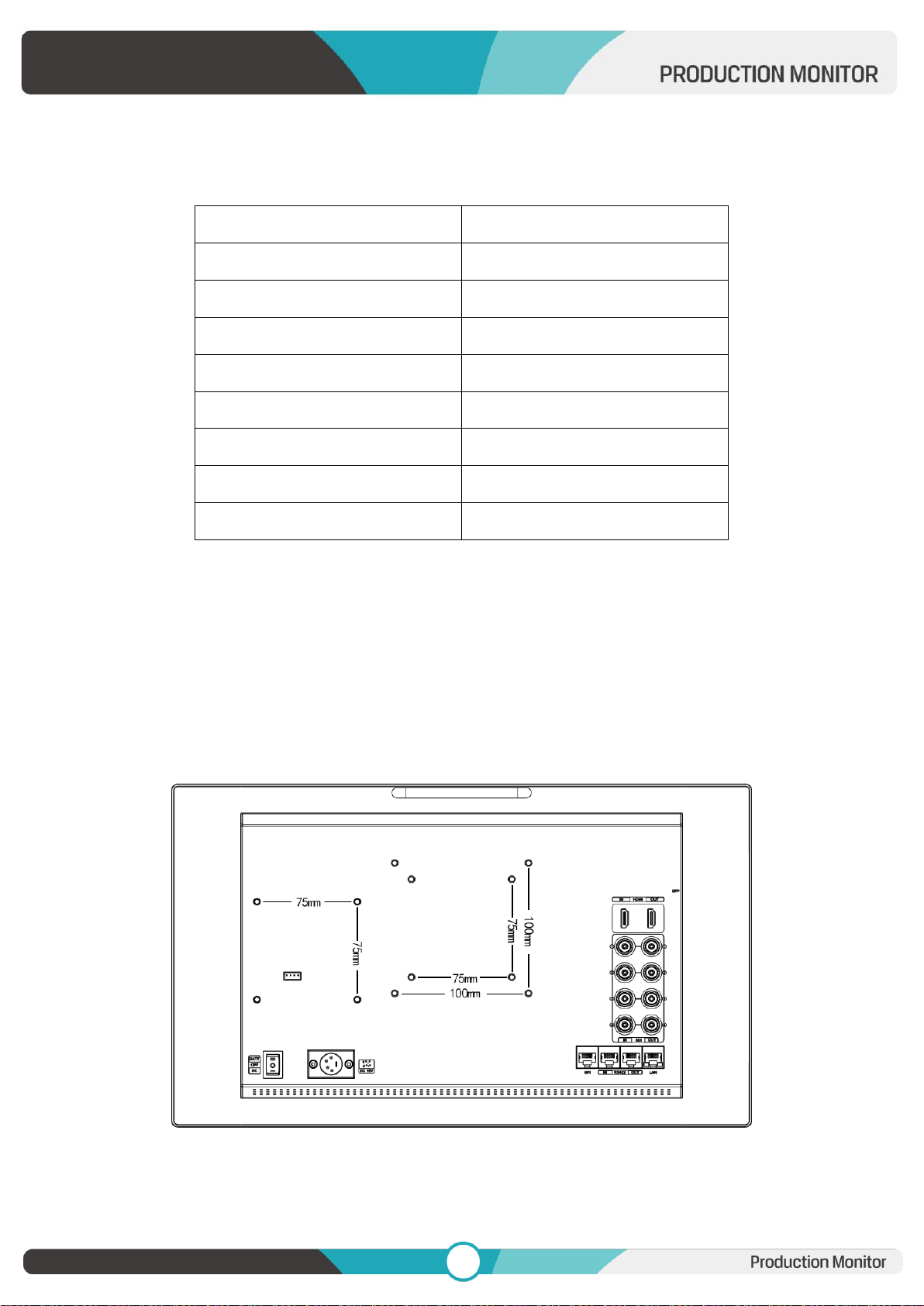
2.2.1 Interfaces
1) 4pin power input for V-mount/ Anton Bauer mount battery plate.
2) Power Switch: “O” is power off, “II” is battery power supply, “I” is DC power supply.
3) Power IN: 4-pin XLR DC.
4) SFP Input
5) HDMI 2.0 Input
6) HDMI 2.0 Output
7) SDI Input
- 12G-SDI Input *4
8) SDI Output
- 12G-SDI Output *4
9) GPI Input (RJ45, 8-pin): See Page 22 GPI 1-8.
Page 7
6
6
PIN Number
Instruction
PIN 1
Y
PIN 2
Z
PIN 3
A
PIN 4
NC
PIN 5
NC
PIN 6
B
PIN 7
NC
PIN 8
GND
10) RS422 Input (RJ45, 8-pin): Supporting the default and TSL V3.1 protocols to control Monitor.
Follow this instructions about this port.
11) RS422 Output (RJ45, 8-pin): Supporting the default and TSL V3.1 protocols to control Monitor. The
instructions about the port is as above.
12) LAN (10/ 100) Input (RJ45): Supporting the default protocol to control Monitor.
Note: The "RemoteTerminal.exe" as default protocol to control Monitor.
2.2.2 Standard VESA
Standard 75mm*75mm is used for external battery (V-mount/ Anton Bauer mount battery).
Standard 75mm*75mm and 100mm*100mm, can be used for external hanging bracket.
Page 8
7
7
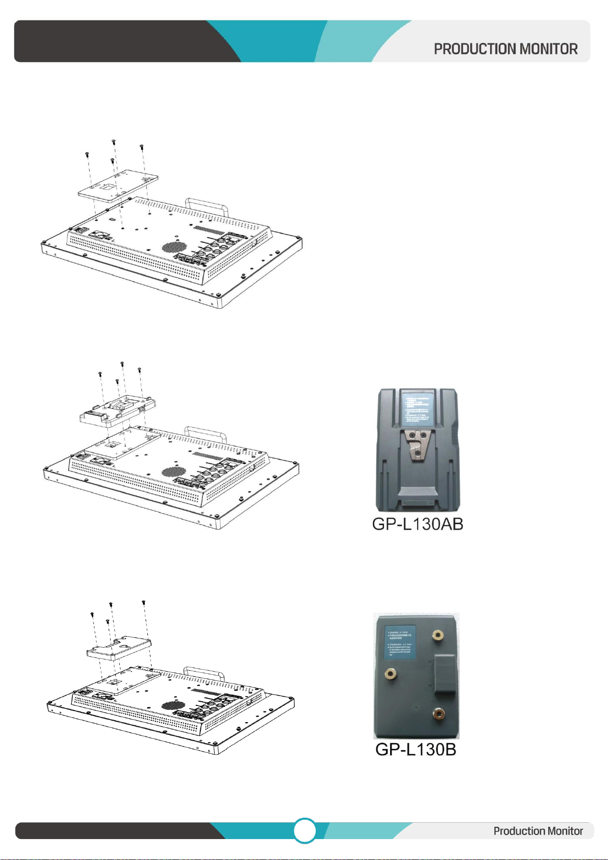
Process of Installing Battery Plate:
- Install the plate base before installing the battery plate.
- Standard with V-mount battery plate: Referring to the following pictures for installation process and GPL130AB type battery.
- Optional Anton Bauer battery plate. Referring to the following pictures for installation process and GPL130B type battery.
Page 9
8
8
3. Menu Setting
Before setting the functions, please make sure the device is connected correctly.
3.1 Shortcut keys
3.1.1 Menu Knob
Power on the monitor, press Menu Knob to display OSD, and select options as the following sequence
via rotating it: PICTURE/ MARKER/ FUNCTION/ WAVEFORM/ AUDIO/ REMOTE/ SYSTEM.
Press Menu Knob to enter the desired function, rotate it to change the value/ option, and press Menu
Knob or Exit again to confirm the changes.
Functions of Menu Knob can be customized: [Back Light], [Brightness], [Contrast], [Saturation], [Tint],
[Sharpness], [Volume], [Peaking Level]. After setting the Knob’s customized function, rotating it can
display the function, and rotating it again can adjust the value. Press it to switch to the next option in
turn. Default option: [Volume].
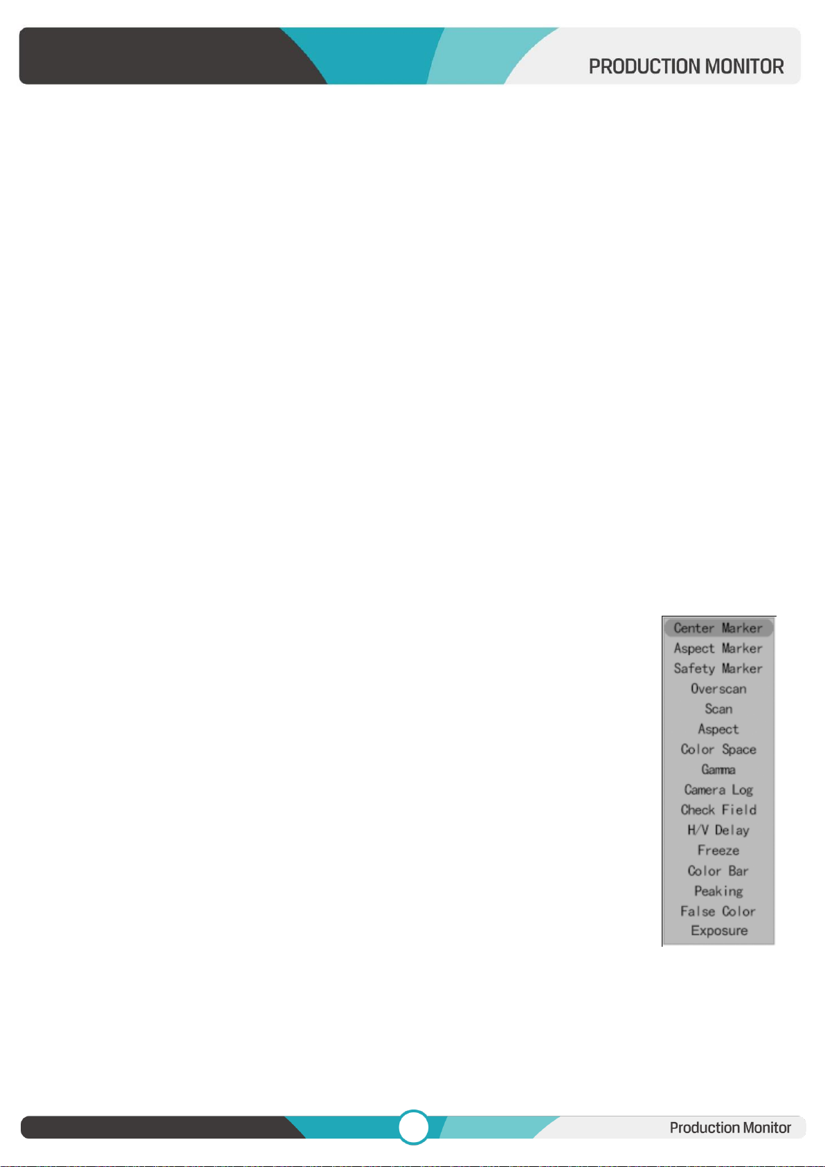
3.1.2 F1-F2-F3-F4 Buttons:
Long press any F1-F2-F3-F4 buttons for 3-5 seconds to pop up shortcut menu on the
screen. As shown in Figure. Select option via rotating the Menu Knob, and set it as
default via pressing the Knob, then press Exit button to exit shortcut setting menu.
The customized function will be remembered by F1/F2 buttons.
Functions of F1-F2-F3-F4 buttons can also be customized: [Center Marker], [Aspect
Marker], [Safety Marker], [Overscan], [Scan], [Aspect], [Color Space], [Gamma],
[Camera Log], [Check Field], [H/V Delay], [Freeze], [Color Bar], [Peaking], [False
Color], [Exposure], [Histogram], [Waveform], [Vector], [Time Code], [Mute], [Level
Meter], [ Audio Vector] and [MV Mode] .
Default function: F1: [Peaking] F2: [Waveform].
F3: [Level Meter] F4: [Color Space].
Page 10
9
9
3.2 MENU Operations
3.2.1 PICTURE
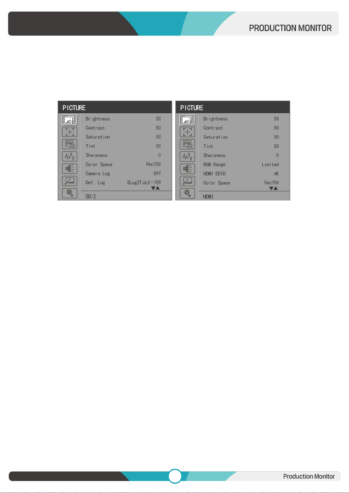
SDI Mode HDMI Mode
Brightness
Control the degree of brightness between 0-100.
Contrast
Control contrast ratio between 0-100.
Saturation
Adjust the color intensity between 0-100.
Tint
Adjust tint between 0-100.
Sharpness
Control sharpness of the image between 0-100.
RGB Range
Use this item to choose the RGB range of the HDMI input: [Full], [Limited].
HDMI EDID
Select the HDMI EDID from between [4K] and [2K]. This item enables PC or other devices to recognize
the property of this monitor and makes the images look excellent on the screen.
Color Space
Select the display gamut from among [Native], [SMPTE-C], [Rec709], [EBU], [DCI-P3], [BT2020].
Note: for the 17.3inch and 31.5 inch monitor, the gamut can be selected among of [DCI-P3], [Native], [SMPTE-
Page 11
10
10
C], [Rec709], [EBU] and [BT2020].
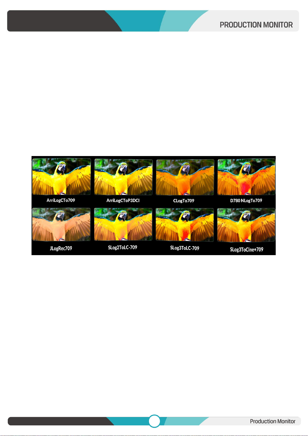
Camera Log
Use this item to choose one of the camera Log modes:
- [Off]: Turn off Camera Log.
- [Def. Log]: Use this item to choose one of the Camera Log modes as the following sequence:
[SLog2ToLC-709], [SLog2ToLC-709TA], [SLog2ToSLog2-709], [SLog2ToCine+709], [SLog3ToLC-709],
[SLog3ToLC-709TA], [SLog3ToSLog2-709], [SLog3ToCine+709],[ArriLogCTo709], [ArriLogCToP3DCI],
[CLogToV709], [VLogToV709], [JLog To709], [JLogTo709HLG], [JLogTo709PQ], [Z7 NLogTo709], [D780
NLog To709].
- [User Log]: Use this item to choose one of the User Log modes (1-6). Please install the User Log as
following steps:
The User Log must be named with. cube in the suffix. Please note: the device only supports the format
of User Log: 17x17x17 / 33x33x33; Data order is BGR; Table order is BGR. If the format does not meet
the requirement, please use tool “Lut Tool.exe” to transform it. Naming the User Log as User1-
User6.cube, then copy the user Log into USB flash disk. Insert the USB flash disk to the device, the
User Log is saved to the device automatically at the first time. If the User Log is not loaded for the first
time, the device will pop up a prompt message, please choose whether to update or not.
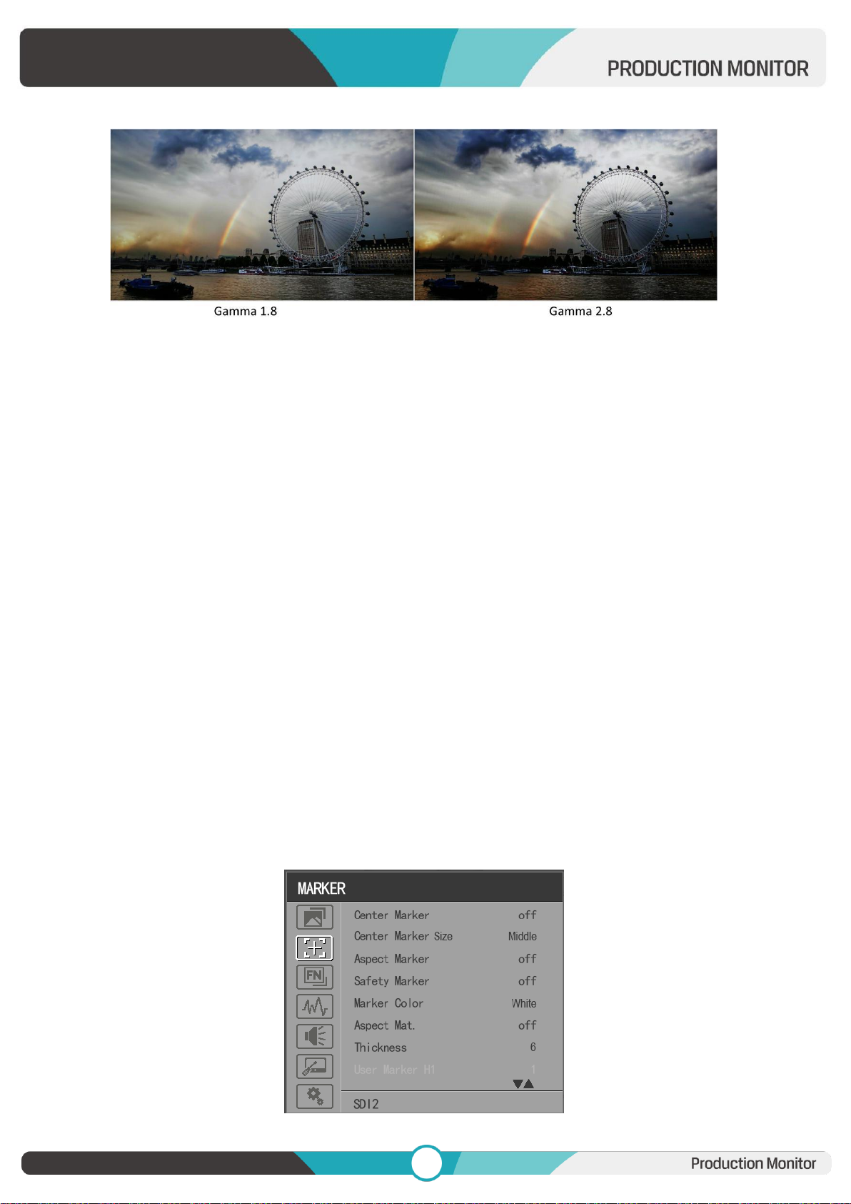
Gamma
Use this item to choose the display Gamma: [Off], [1.8], [2.0], [2.2], [2.35], [2.4], [2.6], [2.8].
Page 12
11
11
Note: Gamma mode can be only activated while HDR function closed.
HDR
Use this item to choose one of the HDR presets: [Off], [ST 2084 300], [ST 2084 1000], [ST 2084 10000],
[HLG].
Back Light Mode
Adjust the level of the back light from 0 to 100.
Color Temp.
Use this item to choose one of the color temperature presets: [3200K], [5500K], [6500K], [7500K],
[9300K], [User].
Note: Only available under [User] mode to adjust R/G/B Gain and Offset.
R/G/B Gain
Adjust the R/G/B Gain of the current Color Temperature from 0 to 255. Default value: 128.
R/G/B Offset
Adjust the R/G/B Offset of the current Color Temperature from 0 to 511. Default value: 256.
3.2.2 MARKER
Page 13
12
12
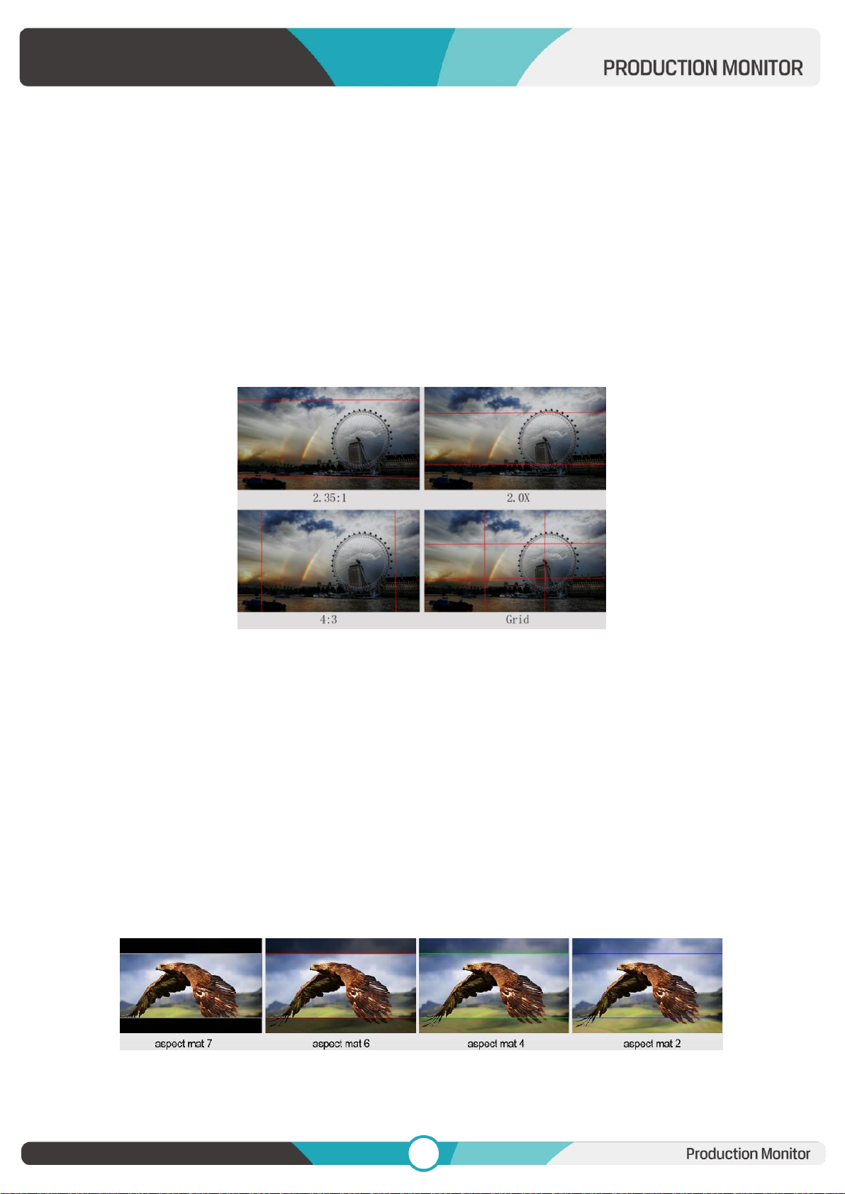
Center Marker
Select [On] to display the center marker “+” and [Off] not to display it.
Center Marker Size
When [Center Marker] is activated, its size can be selected. [Small], [Middle] and [Large] are for option
al. Default option: [Middle].
Aspect Marker
Select the aspect ratio of the marker: [Off], [16:9], [1.85:1], [2.35:1], [4:3], [3:2], [2.0X], [2.0X MAG],
[Grid], [User].
Safety Marker
- Select [Off] not to display the safety marker. When this item is used with the aspect marker, it is only
in aspect marker. When [Aspect Marker] is selected as [User], the safety marker does not be changed.
- Select the size of the safety markers: [95%], [93%], [90%], [88%], [85%], [80%].
Note: When [Aspect Marker] is selected as [Grid], the safety marker cannot be displayed.
Marker Color
Select the color of marker displayed on the screen: [Red], [Green], [Blue], [White], [Black].
Aspect Mat.
When activated, it can be selected from 1-7 (Step value is 1).
Page 14
13
13
Thickness
Adjust the thickness of all the marker lines from 1-15 (Step value is 1).
User Marker
H1/H2: Adjust the position of vertical markers from 1 to 3840 (Step value is 1).
V1/V2: Adjust the position of horizontal markers from 1 to 2160 (Step value is 1).
Note: User maker only in [Aspect Maker]- [User] mode available.
Note: The Marker function is not available in Quad Mode.
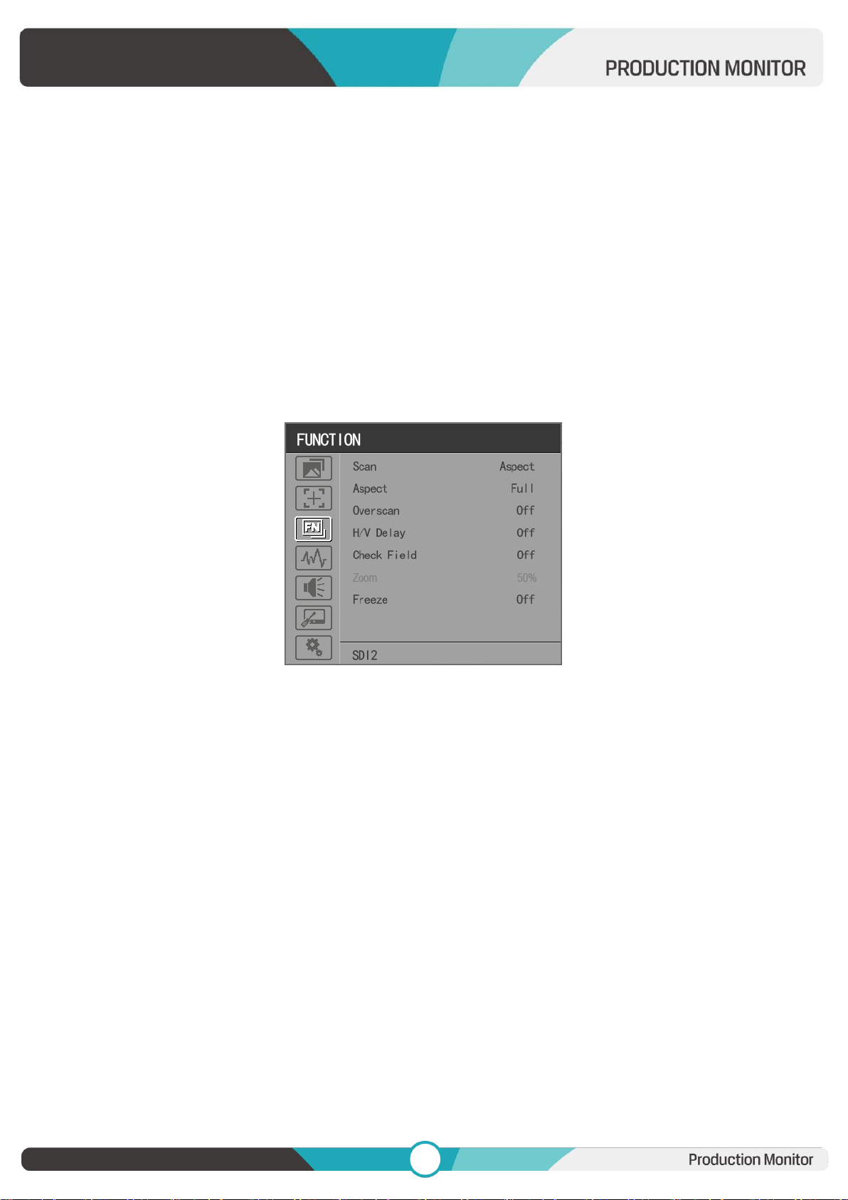
3.2.3 FUNCTION
MV Mode:Off, Quad
MV1 Source: SDI1/SDI2/SDI3/SDI4/SFP/HDMI signal input
MV2 Source: SDI1/SDI2/SDI3/SDI4/SFP/HDMI signal input
MV3 Source: SDI1/SDI2/SDI3/SDI4/SFP/HDMI signal input
MV4 Source: SDI1/SDI2/SDI3/SDI4/SFP/HDMI signal input
Frame Line Color: Off, 2, 4, 6, 8, 10, 12, 14
MV1 Frame Line Color: White, Red, Green, Blue, Yellow, Cyan, Magenta
MV2 Frame Line Color: White, Red, Green, Blue, Yellow, Cyan, Magenta
MV3 Frame Line Color: White, Red, Green, Blue, Yellow, Cyan, Magenta
MV4 Frame Line Color: White, Red, Green, Blue, Yellow, Cyan, Magenta
Scan
Adjust the scan mode among [Aspect], [Pixel To Pixel], [Zoom].
Note: Aspect and overscan functions only can be adjusted only under [Aspect] mode. Both of them cannot
Page 15
14
14
be adjusted in [Zoom] and [Pixel To Pixel] modes.
Note: The Scan function is not available in Quad Mode.
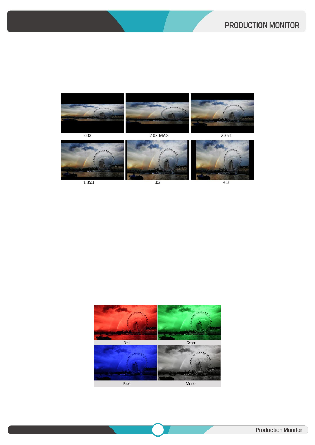
Aspect
Select the aspect of the image among [Full], [16:9], [1.85:1], [2.35:1], [4:3], [3:2], [2.0X], [2.0X MAG].
Note: The Aspect function is not available in Quad Mode.
Overscan
Use this item to activate or deactivate overscan.
Note: The Overscan function is not available in Quad Mode.
H/V Delay
Select one of the H/V modes: [OFF], [H], [V], [H/V]. When H/V Delay on, the blanking portions of the
input signal will be displayed horizontally and vertically.
Note: The H/V Delay function is not available in Quad Mode.
Check Field
Select one of check field modes: [Off], [Red], [Green], [Blue], [Mono].
Zoom
Page 16
15
15
Select zoom scale from 10% to 90% (Step value is 10%).
When you select [Scan] as [Zoom], any part of the enlarged image can be displayed on the screen via
the Menu Knob.
Note: The Zoom function is not available in Quad Mode.
Freeze
Choose [On] to capture one frame of current image on the screen, and choose [Off] to close freeze
function.
Note: The Freeze function is not available in Quad Mode.
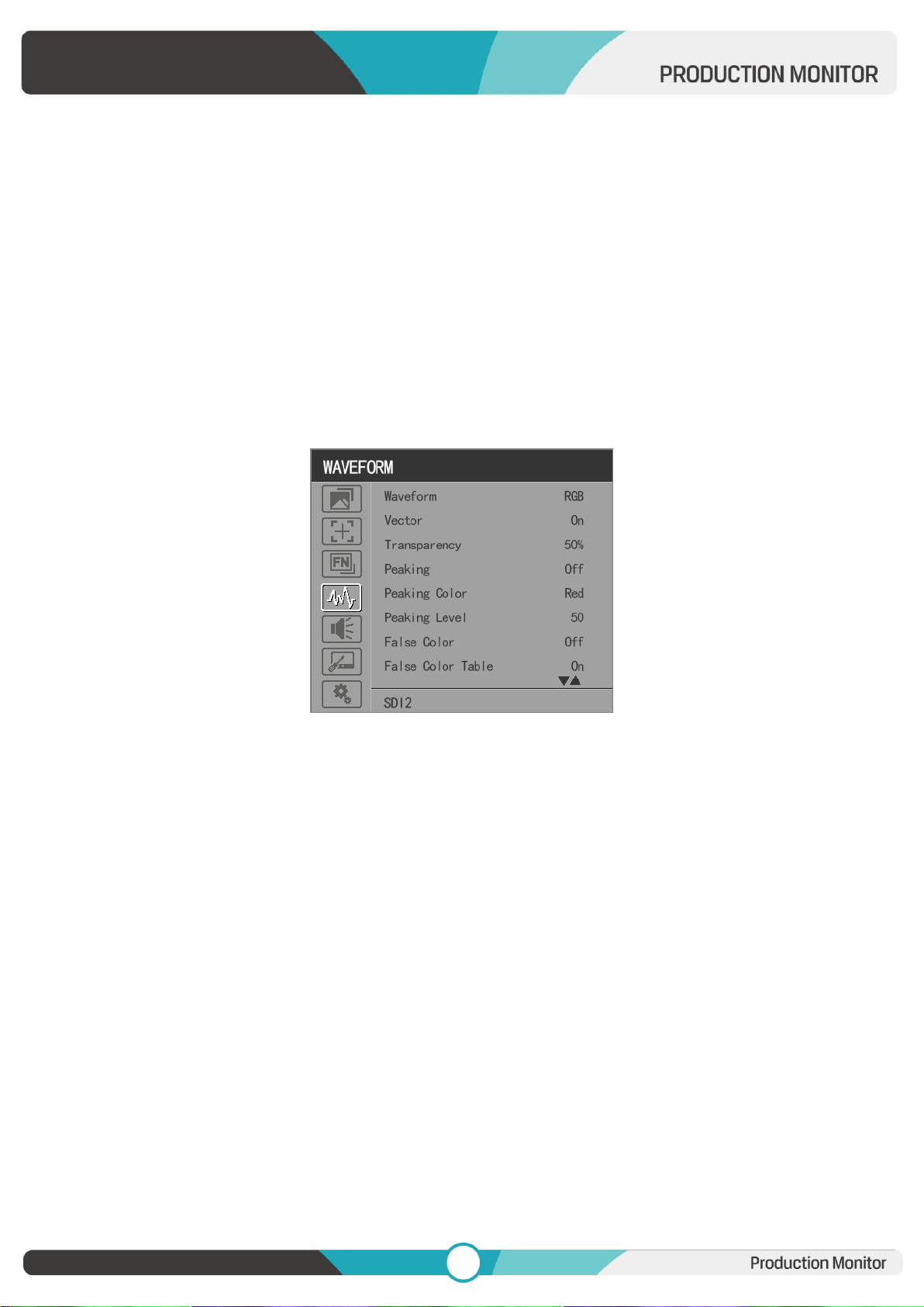
3.2.4 WAVEFORM
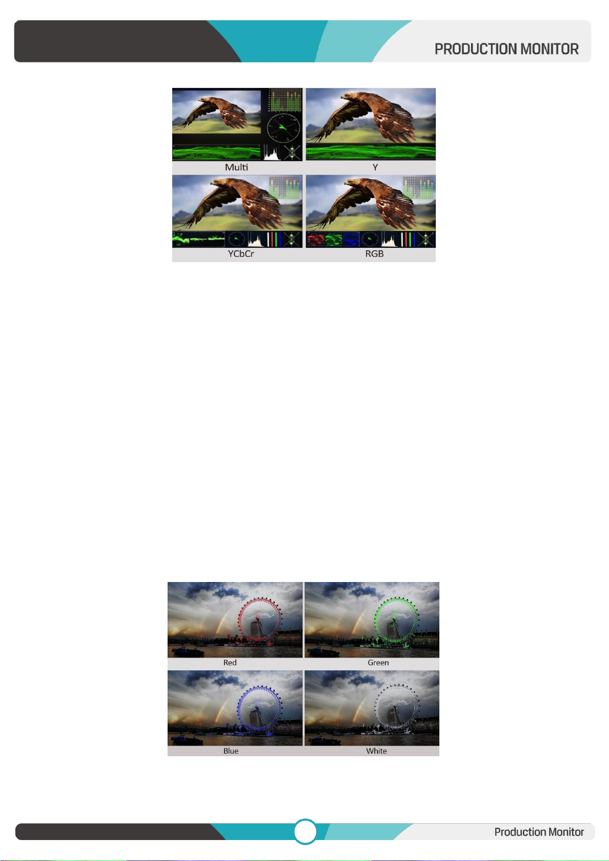
Waveform
Use this item to activate or deactivate Waveform. Select the waveform mode from among [Multi], [Y],
[YCbCr], [RGB].
- [Multi]: Display waveform, histogram, audio vector, vector, and level meter simultaneously.
- [Y]: Display Y Waveform.
- [YCbCr]: Display YCbCr Waveform.
- [RGB]: Display R/G/B Waveform.
Page 17
16
16
Note: The Waveform function is not available in Quad Mode.
Vector
Use this item to activate or deactivate Vector.
Note: The Vector function is not available in Quad Mode.
Transparency
Adjustment of transparency can support waveform, vector, histogram, audio vector, level meter.
Transparency can be selected from among [off], [25%], and [50%].
- [Off]: The background of waveform is shown at black.
- [25%]: The background of waveform is shown at 25% intensity.
- [50%]: The background of waveform is shown at 50% intensity.
Peaking
Use this item to activate or deactivate the peaking function.
Peaking Color
Select one of the peaking colors: [Red], [Green], [Blue], [White], [Black].
Peaking Level
Page 18
17
17
Use this item to adjust the level of peaking from 1-100. The higher peaking level is, the more obvious
peaking effect is.
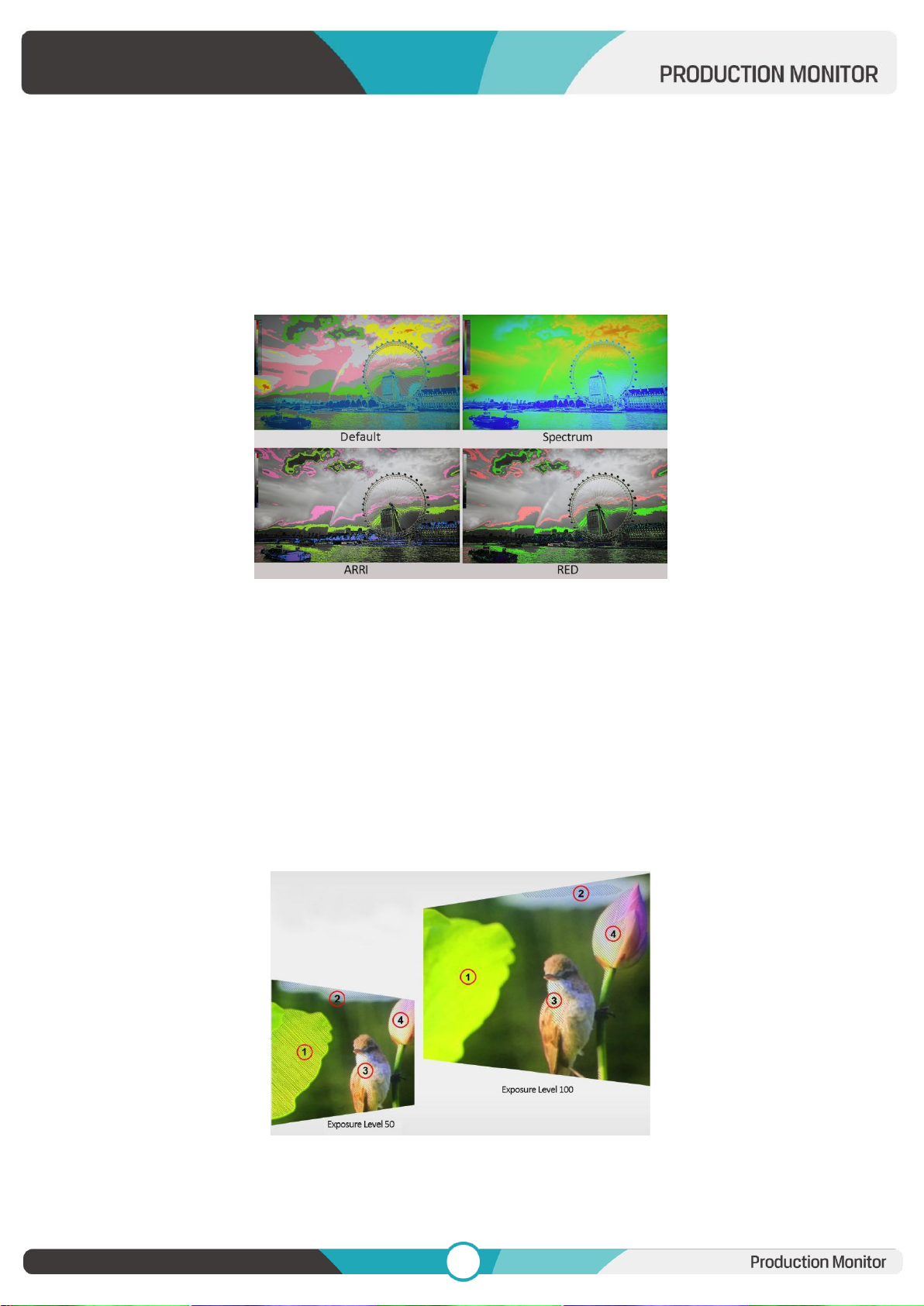
False Color
Use this item to activate or deactivate the false color function.
When activated, [Default], [Spectrum], [ARRI], [RED] are for optional.
False Color Table
Use this item to activate or deactivate the false color table. The range of the false color table is
between 0-100 IRE.
Exposure
Use this item to activate or deactivate the exposure function.
When activated, exposure works if the input signal exceeds the designated exposure level.
Exposure Level
Use this item to adjust the level of exposure between 50-100 IRE.
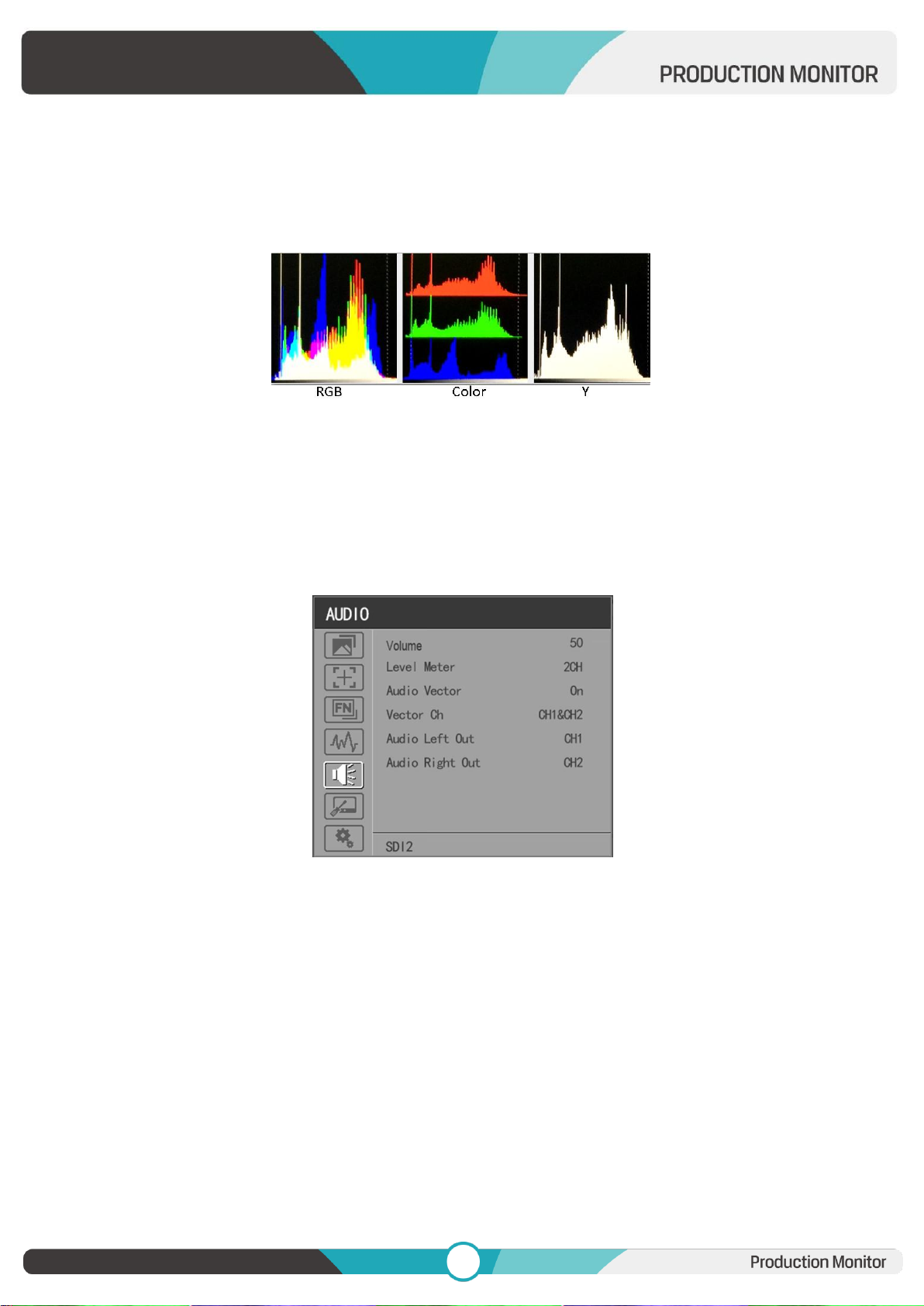
Histogram
Use this item to activate or deactivate histogram. When activated, [Y], [RGB], [Color] are for optional.
Page 19
18
18
- [Y]: Display Y histogram.
- [RGB]: Display RGB mixed histogram.
- [Color], Display RGB separated histogram.
Note: The Histogram function is not available in Quad Mode.
Time Code
Use this item to activate or deactivate the Time Code. When activated, [LTC], [VITC] are for optional.
Note: Time code is only available under SDI mode.
3.2.5 AUDIO
Volume
Adjust the volume among 0-100.
Audio Source:SDI1/SDI2/SDI3/SDI4/SFP/HDMI
Note: The Audio Source is only available under Quad mode.
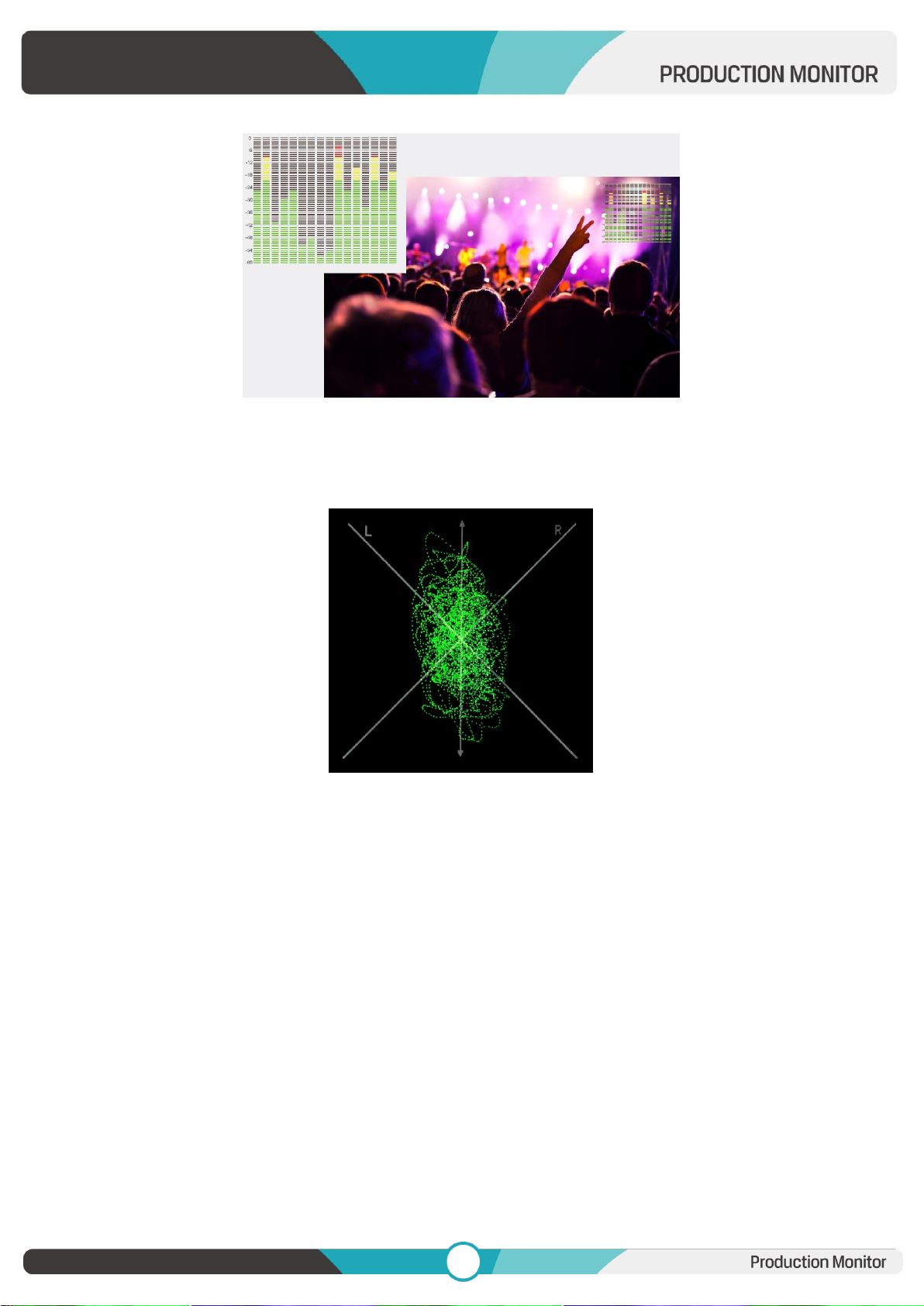
Level Meter
Option: Off, 2CH, 4CH, 8CH, 16CH.
Note: Default as on under [Waveform]-[Multi] function.
Page 20
19
19
Audio Vector
Select whether to activate or deactivate audio vector. Audio phase can be monitored by the audio
vector.
Note: The Audio Vector is not available under Quad mode.
Vector Ch.
In HDMI mode, select the vector channels from among [Ch1&Ch2], [Ch3&Ch4], [Ch5&Ch6], and
[Ch7&Ch8].
In SDI mode, select the Vector Channels from among [Ch1&Ch2], [Ch3&Ch4], [Ch5&Ch6], [Ch7&Ch8],
[Ch9&Ch10], [Ch11&Ch12], [Ch13&Ch14], and [Ch15&Ch16].
Note: The Vector Ch is not available under Quad mode.
Audio Left/Right Out
In HDMI mode, select one of the audio channel from among 1-8.
In SDI mode, select one of the audio channel from among 1-16.
Note: The Audio Left/Right Out is not available under Quad mode.
Page 21
20
20
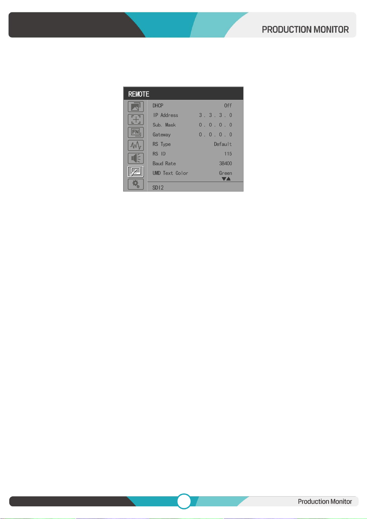
3.2.6 REMOTE
DHCP
- [On]: The monitor will automatically get an IP address from network for remote control via various
programs.
- [Off]: Manually configure IP address.
IP Address
Manually configure IP address: xxx.xxx.xxx.xxx
Note: When [DHCP] on, IP address cannot be manually set .
Sub net Mask
Manually configure Sub net Mask: xxx.xxx.xxx.xxx
Note: When [DHCP] on, Sub net Mask cannot be manually set .
Gateway
Manually configure Gateway: xxx.xxx.xxx.xxx
Note: When [DHCP] on, Gateway cannot be manually set .
RS Type
Select RS type: [Default], [TSL V3.1].
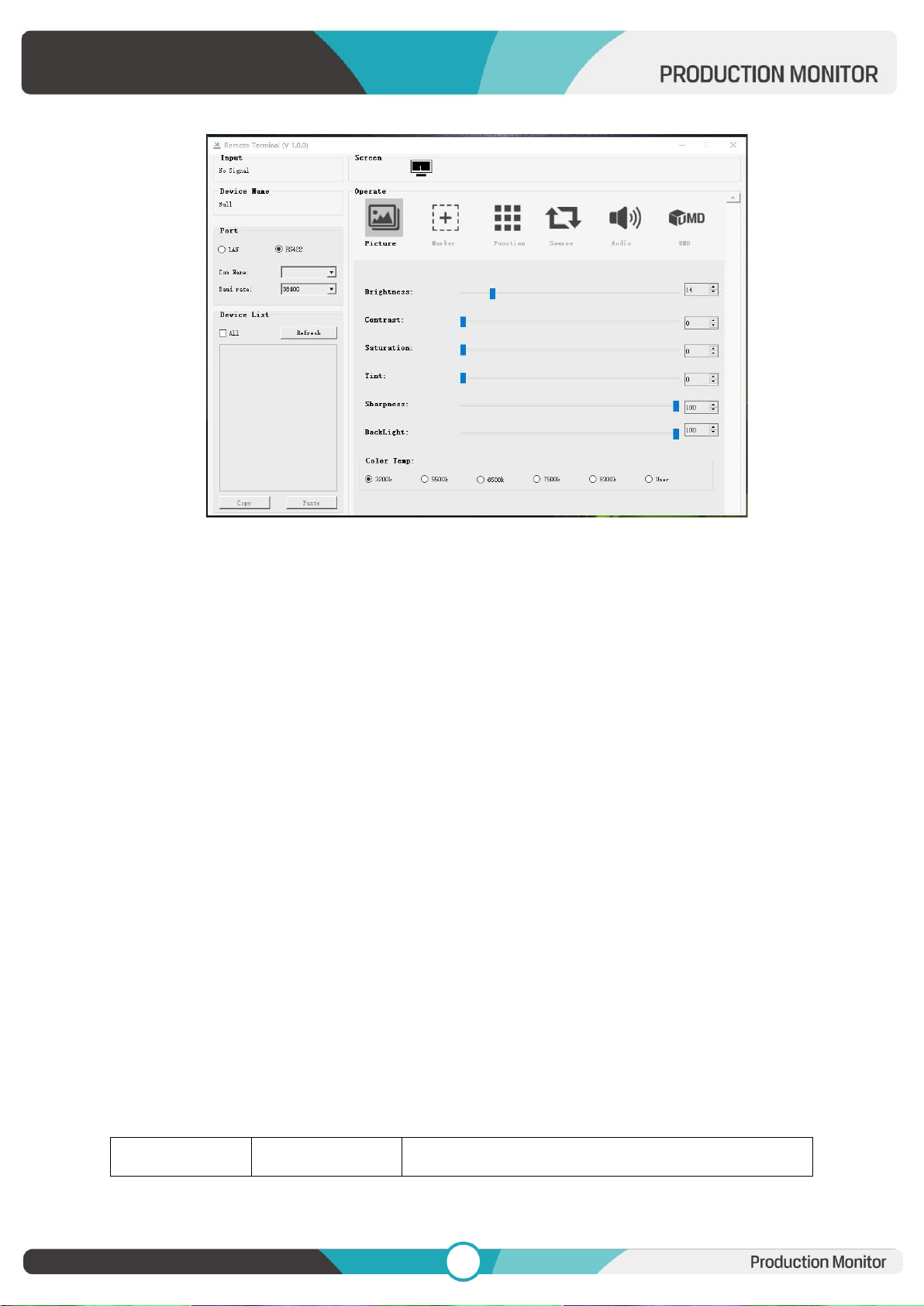
Default software connection as below,
Page 22
21
21
PIN Number
GPI
Settable Values
RS ID
Set the ID of RS422 communication. The valid address range is between 1-126.
Note: ID must be unique in a RS422 network.
Baud Rate
Select one of RS422 Baud Rate: [19200], [38400], [57600].
Note: Set the same Baud Rate in PC’s monitoring software.
Note: The Baud Rate is not available under Quad mode.
UMD
UMD 1: Off, On
UMD 1 Text Color: White, Red, Green, Blue, Yellow, Cyan, Magenta
UMD 2: Off, On
UMD 2 Text Color: White, Red, Green, Blue, Yellow, Cyan, Magenta
UMD 3: Off, On
UMD 3 Text Color: White, Red, Green, Blue, Yellow, Cyan, Magenta
UMD 4: Off, On
UMD 4 Text Color: White, Red, Green, Blue, Yellow, Cyan, Magenta
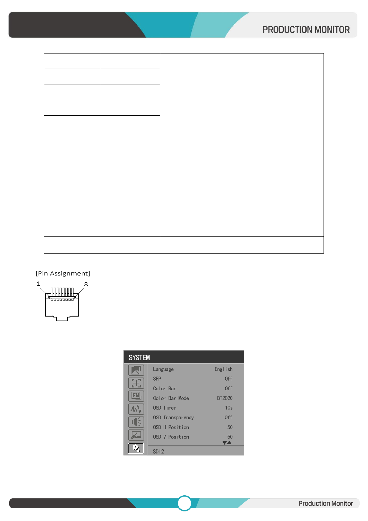
GPI 1-8
Page 23
22
22
1
1
Single/ 2SI/ SQUARE
HDMI
Center Marker
16:9 Marker/ 1.85:1 Marker/ 2.35:1 Marker/ 4:3
Marker/ 3:2 Marker/ 2.0X Marker/ 2.0X MAG
Marker/ Grid
SA 95%/ SA 93%/ SA 90%/ SA 88%/ SA 85%/ SA 80%
Pixel To Pixel
Blue Only
H/V Delay
Peaking
False Color
Exposure
Mute
Level Meter
Audio Vector
Tally Red/ Tally Green
2 2 3 3 4 4 5
5
6
6
7
7
Power
8
Gnd
GND
The GPI function is activated when the GPI pin is connected with the ground, and
closed when it is disconnected from the ground. Connect to GPI to control the
monitor remotely.
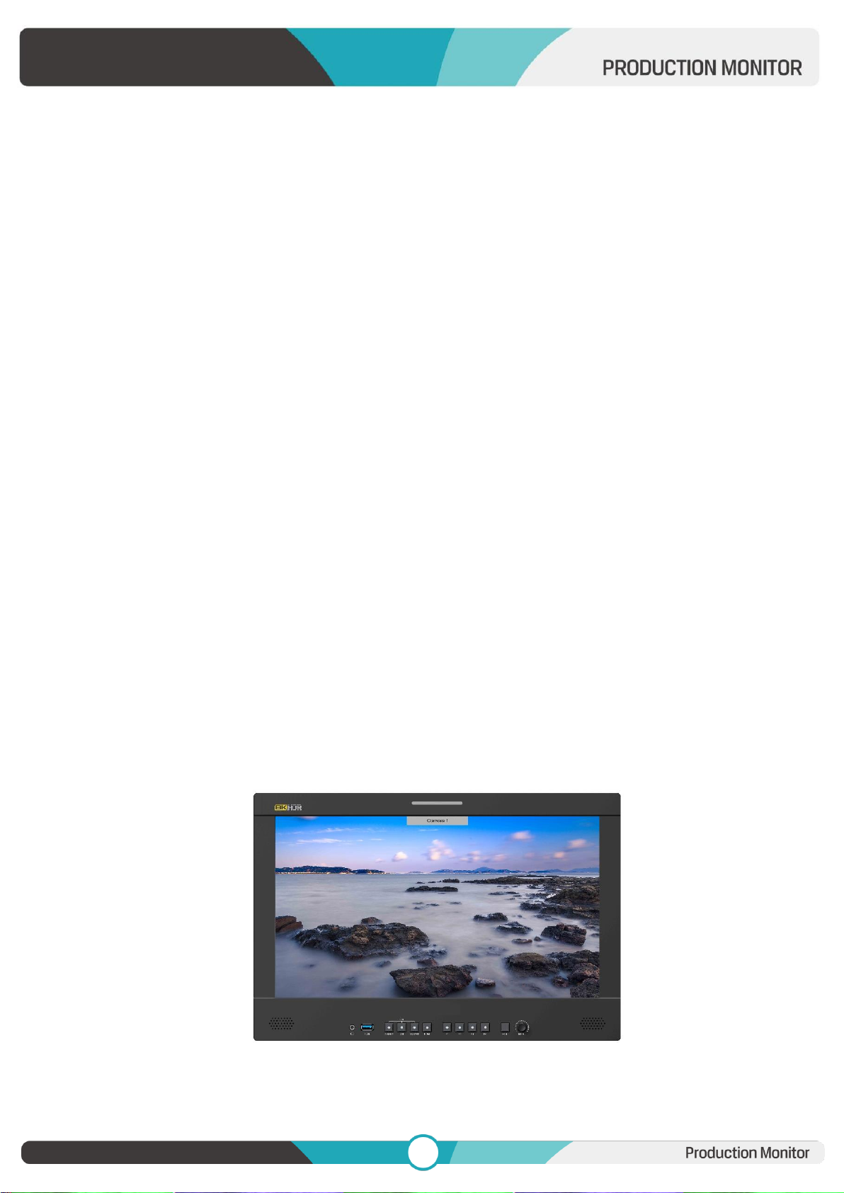
3.2.7. SYSTEM
Language
Option: [Chinese], [English].
Page 24
23
23
SFP
Option: [On], [Off].
When the SFP on, SFP signal input can be selected via SDI-Single button on the front panel.
Color Bar
Turn on/off color bar. When the color bar on, it can be selected: [100%], [75%].
Note: The Color Bar Mode is not available under Quad mode.
Color Bar Mode
Option: [Rec601], [Rec709], [BT2020] color space.
Note: The Color Bar is not available under Quad mode.
OSD Timer
Option: [10s], [20s], [30s].
OSD Transparency
Turn on/off OSD transparency. When OSD Transparency on, option: [25%], [50%].
OSD H Position
Option: 0-100. Default: 50.
OSD V Position
Option: 0-100. Default: 50.
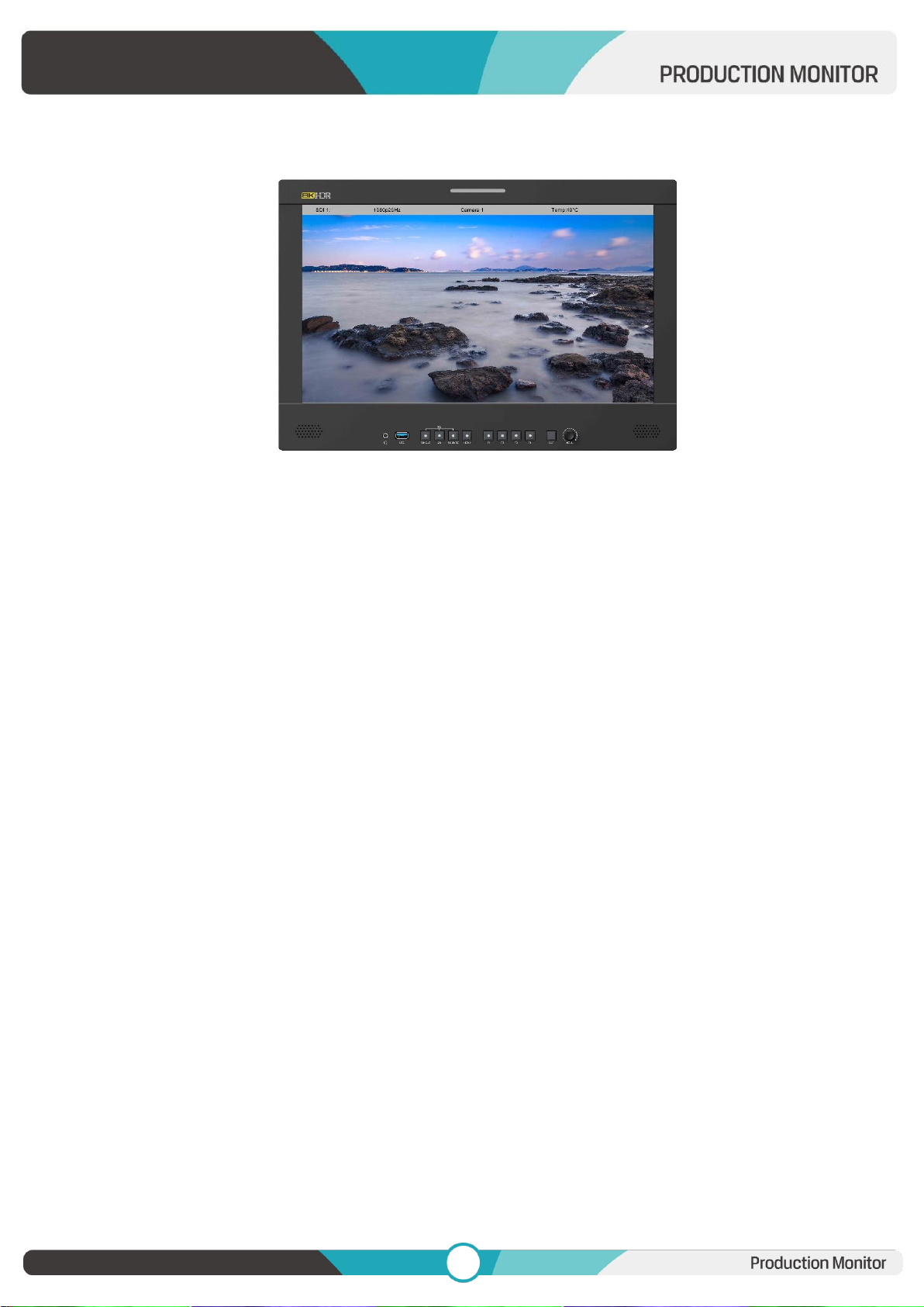
Info. Windows
Option: [Off], [Standard], [Full]. Default: [Off].
- [Standard]: It supports UMD display. As show in the picture below,
- [Full]: it can support signal input, UMD and internal temperature display. As shown in the
Page 25
24
24
following picture,
- UMD feature in the info. windows:
Support user UMD input data on screen, ASCII: 0x20~0x7e
Support display up to 16 characters that are input by TSL protocol V3.1 on the screen.
Note: The Info. Windows is not available under Quad mode.
Info. Windows transparency
Select to turn on/off info. Windows transparency, option: [Off], [25%], [50%]. Default: [Off].
Note: It is not available under Quad mode.
Info. Windows H/V Position
The option range: 0-100.
Note: When [Info. Window] is selected as [Standard], its position can be adjusted freely. When [Info.
Window] is selected as [Full], its vertical position can be adjusted freely.
Fan
Option: [Auto], [On], [Off]. Default: [Auto].
- [Auto]: The monitor will automatically turn on/off the fan according to the setting value of fan auto
temp.
Note: It is not available under Quad mode.
Knob
Customized Knob function, custom option: [Brightness], [Contrast], [Saturation], [Tint], [Sharpness],
[Volume], [Peaking Level], and [Back light]. Default: [Volume]. Please refer to 3.1.1 for Knob specific
operation instructions.
Page 26
25
25
Color Calibration
Select [On] or [Off].
If the device needs to be calibrated color, please operate as following:
Connect the device with the PC via HDMI interface.
Make sure the device and color calibration equipment to work more than 30 minutes.
After the previous step, activate the Color Calibration function of the device and color calibration
software to calibrate the color (See the document “CMS Color Calibration Process” for details).
It will generate a document “Rec709.cube” after calibrated, then copy this document to USB flash
disk.
Insert the USB flash disk to the device and save the document. This document “Rec709.cube” will
be found under Color Space Option.
Note: It is not available under Quad mode.
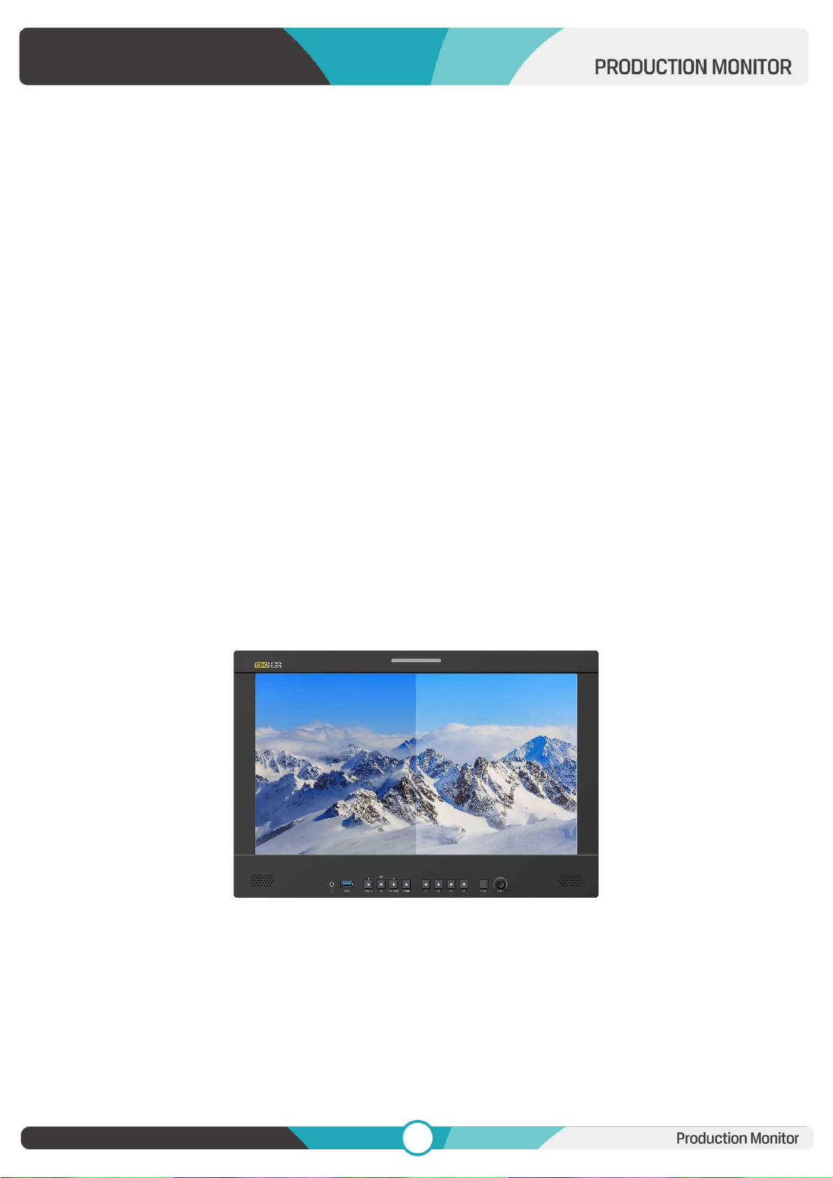
Comparison En
Use this setting to activate or deactivate the Comparison En function.
When activated, the screen displays the comparison of Original image and customized image, as
shown:
Option: [Off], [Gamma/HDR], [Color Space], [Camera Log]. Default: [Off].
Note: It is not available under Quad mode.
Reset
Select the Reset option, press the Menu knob to automatically reset.
Page 27
26
26
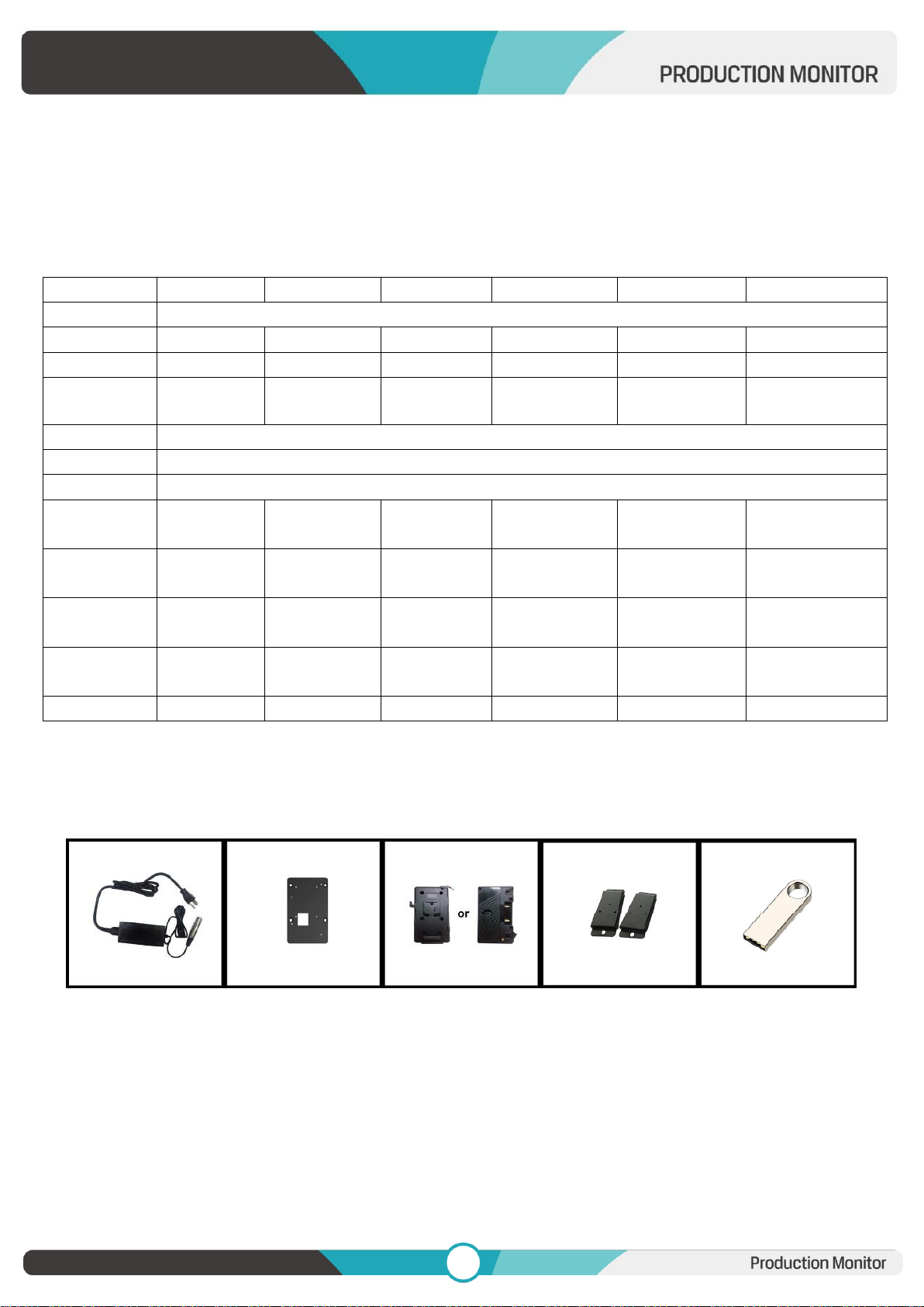
Panel
13.3”
15.6”
17.3”
23.6”
28”
31.5”
Resolution
3840×2160
Brightness
300 cd/m²
600 cd/m²
400 cd/m²
300cd/m²
300cd/m²
350cd/m²
Contrast
1000:1
1700:1
1200:1
1000:1
1000:1
1300:1
Viewing Angle
178°/178°
(H/V)
170°/170°
(H/V)
170°/170°
(H/V)
178°/178°
(H/V)
178°/178°
(H/V)
178°/178°
(H/V)
Input
12G-SDI*4, HDMI 2.0, GPI, RS422, LAN, USB,SFP
Output
12G-SDI*4, HDMI 2.0, RS422, Earphone jack
Power In
DC 12-24V
Power
Consumption
≤
36W (15V)
≤
37W (15V)
≤
40W (15V)
≤
60W (15V)
≤65W (15V)
≤79W (15V)
Operating
Temperature
0~50°C
0~40°C
0~50°C
0~40°C
0~40°C
0~40°C
Storage
Temperature
-20~60°C
-20~60°C
-20~60°C
-20~60°C
-20~60°C
-20~60°C
Dimensions
(LWD)
340×233×46
mm
393×267×51.4
mm
434×294×46
mm
567x376.4x45.7
mm
638x414.3x54.4
mm
717.5x454.7x47.4
mm
Weight
2.4KG
2.9kg
3.9kg
7.4kg
8.6kg
13.0kg
4. Product Parameters
5. Accessories
Standard:
1) 15V/4A DC Adapter 1pc
2) VESA Mount Plate Bracket 1pc
3) V-mount (or Anton Bauer Mount) 1pc
4) Base Bracket 1 pair
5) 8GB USB flash drive (User guide and software included) 1pc
Page 28
27
27
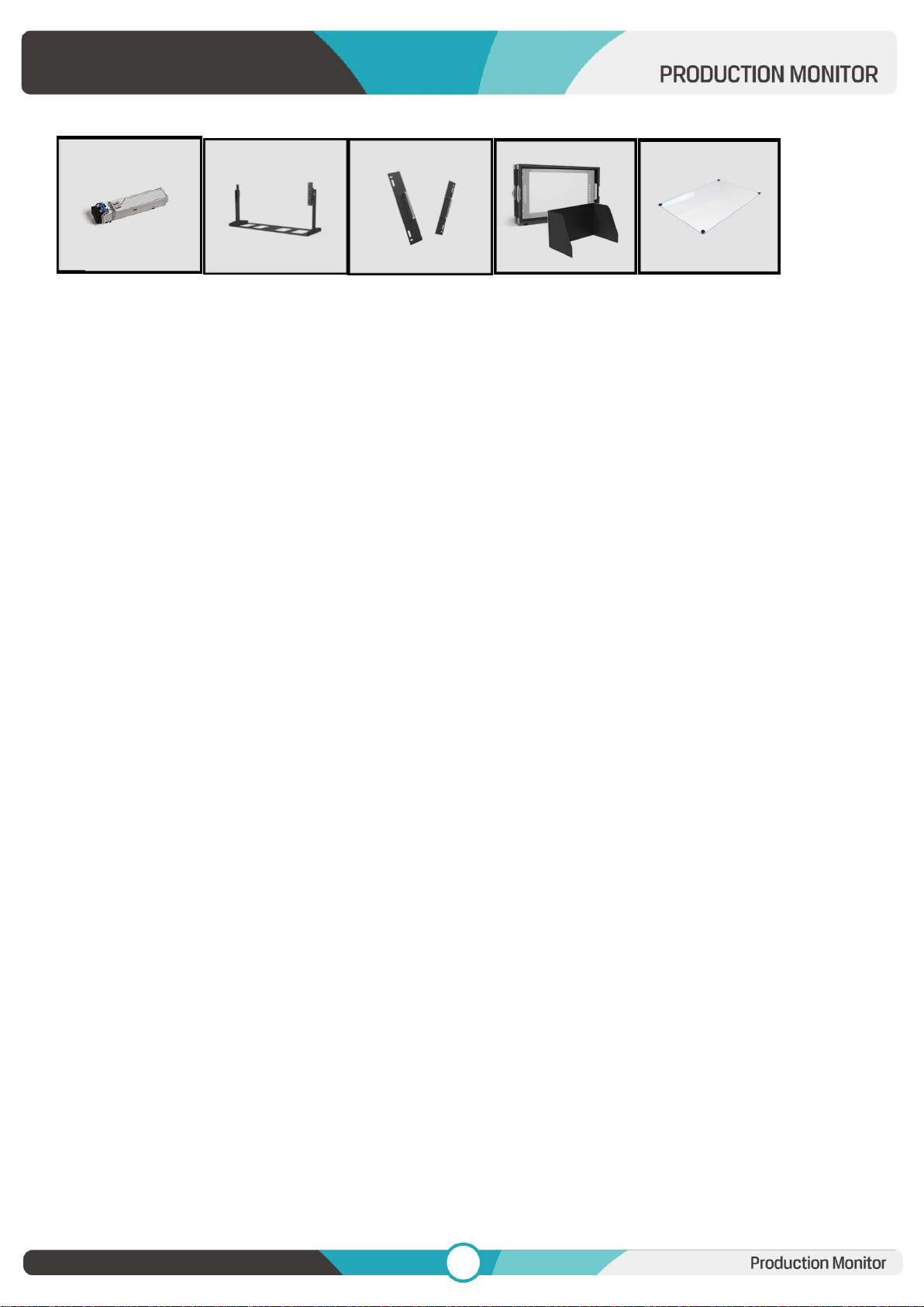
Optional:
6) SFP Optical Fiber Module 1 pc
7) Gimbal Bracket (13.3”,15.6”,17.3”) 1 pc
8) Rack Mount Bracket(13.3”,15.6”,17.3”,23.6”,28”) 1 pc
9) Carrying Case + Sunshade(15.6”,17.3”,23.6”,28”) 1 pc
10) Acrylic Screen Protector(15.6”) 1 pc
6. Trouble Shooting
1) Only black-and-white display:
Check whether the color saturation is properly setup or not.
2) Power on but no pictures:
Check whether the cables of SDI and HDMI are correctly connected or not. Please use the standard power
adapter coming with the product package. Improper power input may cause damage.
3) Wrong or abnormal colors:
Check whether the cables are correctly and properly connected or not. Broken or loose pins of the cables
may cause a bad connection.
4) When on the picture shows size error:
Press “MENU → FUNCTION → Overscan” to zoom in/out pictures automatically when receiving HDMI
signals.
5) Other problems:
Please press “MENU” button and choose “MENU→SYSTEM→ Reset →On”.
Note: Due to constant effort to improve products and product features, specifications may change without
notice.
Page 29
28
28
Appendix 1: 3D LUT Loading
3D LUT supports upload color calibration document and User Log via USB flash disk.
Format Requirement
LUT format
Type: .cube
3D Size: 17x17x17/33x33x33
Data Order: BGR
Table Order: BGR
USB flash disk version
USB: 2.0
System: FAT32
Size: <16G
LUT formatColor calibration document: Rec709. cube
User Log: User1. cube-User6.cube
LUT Format conversion
Please convert LUT format according to the following steps.
Note: For Mac users, please copy the "mac OS" file to Mac, then click and follow the steps below.
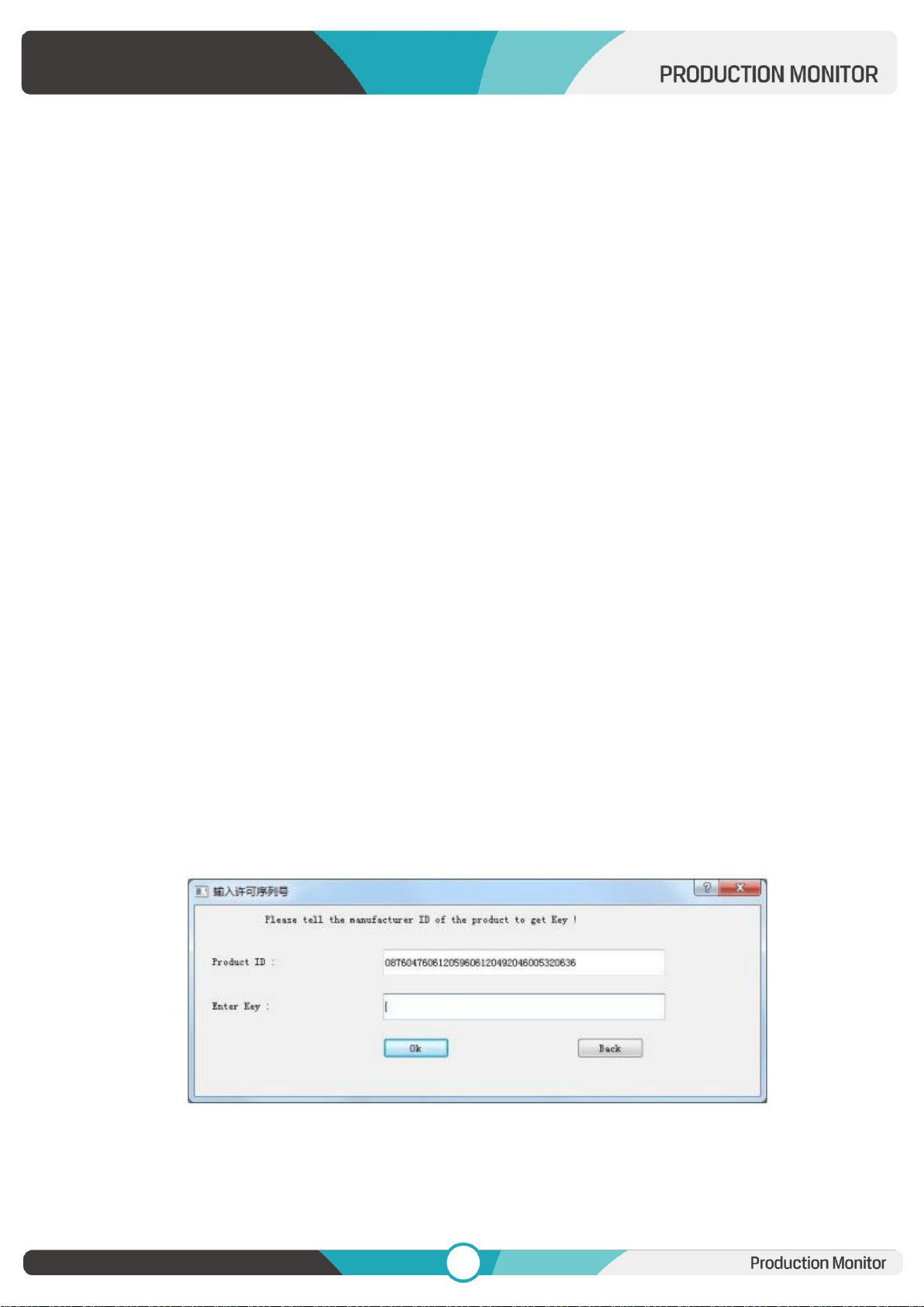
Activate Lut converter
One individual Product ID for one computer. Please send the ID number to Sales to get an Enter Key.
Then the computer gets the permission of the Lut Tool after input the Enter Key.
Page 30
29
29
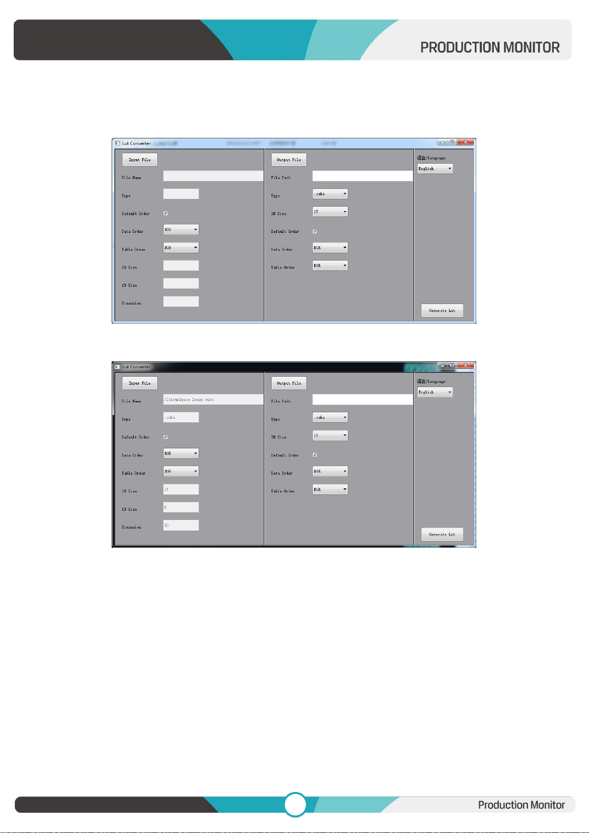
LightSpace CMS software user demo
- Activate LUT Tool.exe.
- Click Input File, then select *LUT.
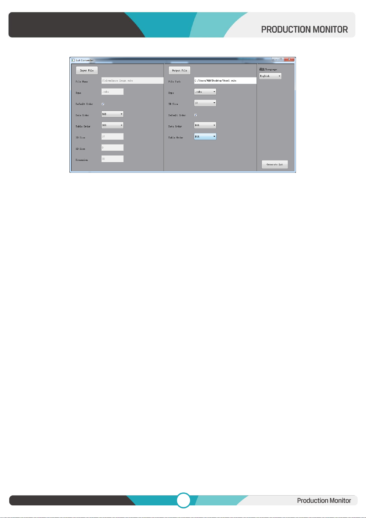
- Click Output File, choose the file name.
Page 31
30
30
- Click Generate Lut button to finish.
USB Loading
Copy the needed files to the root directory of the USB flash disk. Plug the USB flash disk into USB port of the
device after power on. Click “Yes” on the pop-up prompt window (If the device doesn’t pop-up the prompt
window, please check the LUT document name or the USB flash disk version), then press Menu button to
update automatically. It will pop-up a prompt message if the update completed.
Page 32
31
31
Appendix 2: Remote Terminal Instructions
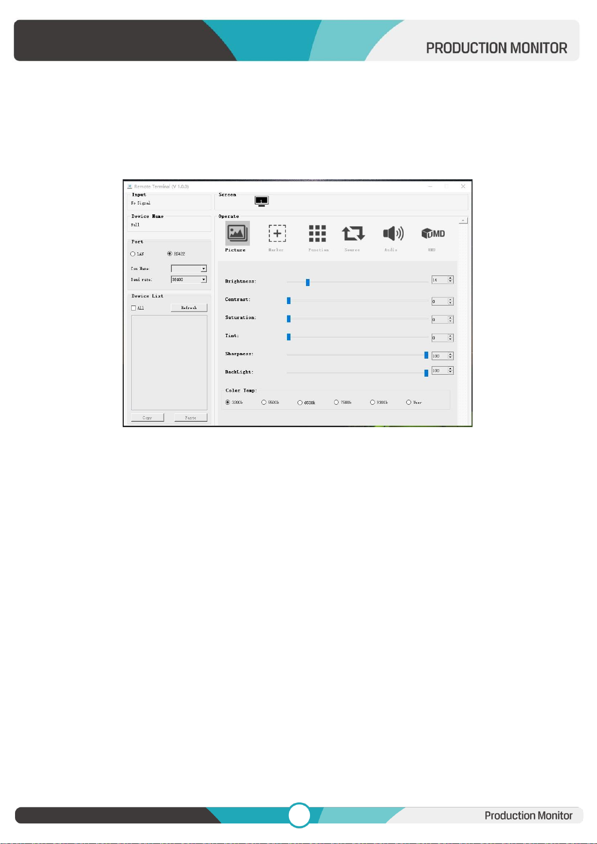
Remotely control the device by Remote Terminal application.
Home Screen
Picture: The home screen of the application
Input: Display the signal format of the connected device. For example, there is “No Signal” when
no device is connected or no signal is input.
Device Name: Display the Model No. of the connected device.
Port: Select the connection way of the port when connecting a device, and support“RS422” or
“LAN” communication protocol.
Device List: Display all of the found peripheral device.
Screen: Display the number of screens for the selected device and the current screen index.
Operate: Operate the items for the device.
Control Screen: The control rules for the device.
Function
Port Selection: Select the specific connection port according to the device interface and click
“RS422” or “LAN” to switch. When RS422 selected, it needs to further set the COM name and
baud rate. For baud rate, it needs to be adapted to the baud rate of the connected device.
Page 33
32
32
Device Search: Click “Refresh” button to search devices after configuring the port. There are all of
the found devices in the device list after a successful search.
Screen Choice: The “Screen” shows the number of the screens for the current device. For the
device with multiple screens, use left mouse button to click the screen icon to select the
corresponding screen for operation; use right mouse button to click the screen icon to copy the
screen.
Device Control: Click the icons of [Picture], [Marker], [Function], [Source], [Audio] and [UMD] to
switch the control page of the corresponding function.
Activate “All”: Simultaneously control all of the devices in the device list if there is two or more
devices with the same model after activating “All”.
Device Copy Function: If there are two or more devices with the same model in the device list,
click one of them and click “Copy” button to copy the source device, and then click the target
device and click “Paste” button to copy the configuration of the source device to the target one.
 Loading...