


BACHMANN EUROPE PLC
Betriebsanleitung
Instruction sheet
L142100-09
H0e
Schmalspur-Diesellokomotive
Bauart Gmeinder
Das LILIPUT-Modell ist die Nachbildung einer der vier von der Gmeinder Lokomotivenfabrik GmbH speziell für
die Zillertalbahn entwickelten und ab 2004 gelieferten neuen Diesellokomotiven vom Typ D 75 BB-SE, die unter
der Bezeichnung D13 bis D16 geführt werden. Zwei weitere Maschinen sind bei der SLB Pinzgauer Lokalbahn
mit der Bezeichnung Vs81 und Vs82 im Dienst. Die Lokomotiven werden vor Personen- und Güterzügen sowie
im Rangierdienst eingesetzt. Außerdem sind zwei Endführerstände sowie eine Wendezugsteuerung vorhanden.
Bei Bedarf können sie mit Meterspur- oder Regelspurdrehgestellen ausgerüstet werden. Die Leistung dieser
Loks beträgt 746 KW (1.040 PS). Die zulässige Höchstgeschwindigkeit liegt bei 80 km/h. Für den Rangierdienst
sind die Loks mit einer Funkfernsteuerungsanlage ausgestattet.
Aus den Badischen Motor-Lokomotiv-Werken hervorgegangen wurde die Gmeinder & Co. GmbH mit Sitz in
Mosbach 1925 gegründet und fertigte Feldbahnen, Normalspurlokomotiven und Grubenbahnen sowie Zahnräder und Zahnradgetriebe.
Nach 1945 wurden weiter Rangierlokomotiven produziert, die speziell an die Deutsche Bundesbahn geliefert
wurden, wie z.B. auch einige Exemplare der Baureihe V 60. Hinzu kamen schmalspurige dieselhydraulische Lokomotiven sowie Dieseltriebwagen. 1976 kam es zum Zusammenschluss von Gmeinder und Kaelble (Backnang)
zur „Kaelble-Gmeinder GmbH. Nach Konkurs dieser Gesellschaft im Jahr 1996 wurde der Gmeinder-Teil verkauft
und es entstand die Gmeinder Lokomotiven- und Maschinenfabrik GmbH. Ende 2003 wurde die Sparte Lokomotivenbau an einen Investor verkauft und firmiert seit 2004 unter Gmeinder Lokomotivenfabrik GmbH. Nach
wie vor werden in Mosbach Diesellokomotiven gebaut und gewartet.
Narrow Gauge Diesel Loco
Type Gmeinder
The LILIPUT model is a replica of one of the four new type D 75 BB-SE diesel locos developed especially for the
Ziller Valley Railway by Gmeinder Lokomotivenfabrik GmbH, of which delivery began in 2004 and which were
given the operating numbers D13 - D16. Two additional locomotives are in service with the SLB Pinzgau local
railway and bear the operating numbers Vs81 and Vs82. The locomotive has been used to pull passenger and
goods trains as well as for shunting work. It is also equipped with two driver cabs as well as a push-pull control.
If required they can be fitted with metre gauge or standard gauge bogies. The locos have a power output of 746
kilowatts (1,040 hp). The permissible maximum speed is 80 km/h. For shunting work the locos are fitted with a
remote control unit.
Gemeinder & Co. GmbH based in Mosbach emerged from the Badische Motor-Lokomotiv-Werke and was
established in 1925. It manufactured narrow gauge track systems, standard gauge locomotives and mining
railways as well as pinions and tooth and rack systems. After 1945 further shunting locomotives were produced
and specifically delivered to the Deutsche Bundesbahn, such as, for example, also some examples of the Class
V 60. These were supplemented by narrow gauge, diesel hydraulic locomotives as well as diesel locomotives.
In 1976 Gmeinder merged with Kaelble (Backnang) to form “Kaelble-Gmeinder GmbH”. After the company
went bankrupt in 1996 the Gmeinder part was sold to form the Gmeinder Lokomotiven- und Maschinenfabrik
GmbH. At the end of 2003 the locomotive construction division was sold to an investor and has traded under
the name Gmeinder Lokomotivenfabrik GmbH since 2004. Diesel locomotives continue to be manufactured and
maintained in Mosbach.
1

BACHMANN EUROPE PLC
Inbetriebnahme Ihres Modells
Nehmen Sie die Lok im Blister vorsichtig aus dem Karton und stellen ihn mit der Lok mit
dem Dach nach oben auf eine feste Unterlage. Der Blister ist mit einer Klippslasche allseitig
verschlossen. Durch hochziehen der Lasche lässt sich der Blister leicht öffnen (Abbil-
dungen 1).
Entnehmen Sie die Lok dem Blister und stellen sie auf das Gleis. Das Modell kann mit
Gleichstrom bis zu einer Spannung von 14 Volt betrieben werden. Lassen Sie die Lok bei
ca. halber Spannung ein paar Minuten vorwärts und rückwärts fahren, danach ist Ihre Lok
betriebsbereit.
Abbildungen 1 Pictures 1
Preparing to operate your model
Carefully remove the locomotive in the blister packing from the box and place it with the
roof uppermost on a firm surface. The blister packing is click sealed on all sides. The blister
packing can be easily opened by lifting the tab (Pictures 1).
Remove the locomotive from the blister packing and place it on the rails. The model can be
operated with direct current up to a voltage of 14 volts. Allow the locomotive to run backwards and forwards at about half voltage for a few minutes. The loco is then ready for use.
2

BACHMANN EUROPE PLC
Wartung und Pflege Ihres Modells
Um eine lange Lebensdauer zu gewährleisten sollte Ihr Modell in regemäßigen Abständen
gewartet werden. Für die kleine Wartung muß das Modell dazu nicht geöffnet werden.
Vielmehr genügt es , wie nach Abbildung 2, das Modell mit dem Dach nach unten auf eine
weiche Unterlage zu legen und mit einem in Spiritus getränkten Wattestäbchen die Radkontakte zu säubern. Danach reinigen Sie die Räder. Drehen Sie dabei bitte auf keinen Fall die
Räder von Hand durch. Nach dem Reinigen schmieren Sie die in Abbildung 2 bezeichneten
Lagerstellen mit einen Tropfen Maschinenöl. Verwenden Sie handelsübliche Öler mit feiner
Kanüle oder einer Stecknadel. Achtung: kein Speiseöl oder Hautcreme verwenden.
S1
Abbildung 2 Picture 2
S1
Looking after your model
In order to ensure that your model functions correctly over a prolonged period your model
should be given maintenance at regular intervals. The model need not be opened for minor
maintenance work. It is sufficient to place the model upside down on a soft surface as
shown in Picture 2 and to clean the wheel contacts using cotton buds dipped in spirits.
Then clean the wheels. However, please do not turn the wheels by hand in any circumstances. After cleaning, please use a drop of machine oil to lubricate the bearing points
shown in Picture 2. Use commercially available oils and use a fine cannula or a needle.
Caution: do not use cooking oil or hand cream.
3

BACHMANN EUROPE PLC
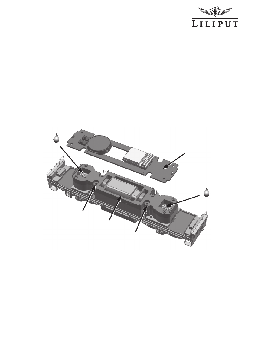
Wartungsarbeiten im Inneren Ihres Modells (Teil 1)
Zum Schmieren des Getriebes, zum Einbau eines Decoders oder zum Austauschen eines
Motores muß das Lokgehäuse demontiert werden. Dazu entfernen Sie die vier Schrauben
S1 auf der Unterseite des Fahrgestelles nach Abbildung 2. Danach können Sie das Gehäuse nach oben gemäß Abbildung 3 abziehen. Auf der Platine oben finden Sie die 21-polige
Schnittstelle DEC zur Montage eines Decoders sowie einen Halter H für einen Lautsprecher
für einen Durchmesser mit 20 mm. Links daneben ist der Multischalter MS für das Frontlichtsystem montiert. Lesen Sie dazu den Abschnitt Frontlichtsystem weiter unten.
S2
MS
H
DEC
Abbildung 3 Picture 3
PCB
K
S2
Maintenance work to the model interior ( Part 1)
The locomotive housing has to be removed to lubricate the gears, install a decoder or to
exchange a motor . To do this remove the four screws S1 on the underside of the bogie as
shown in Picture 2. You can then lift the housing off as shown in Picture 3. The 21-pin interface DEC for the fitting of a decoder is located at the top of the board. It also has a holder
H for a loud speaker for a diameter of 20 mm. To the left of this there is a multiswitch MS
for the front light system. Read the section on the front light system below.
4
BACHMANN EUROPE PLC
Wartungsarbeiten im Inneren Ihres Modells (Teil 2)
Um zum Getriebe zu gelangen demontieren Sie bitte nun die Leiterplatte PCB. Dazu sind
zwei Schrauben S2 zu entfernen und die Kontaktdrähte K von der Leiterplatte zu ziehen.
Sehen Sie dazu Abbildung 4. Nun können die beiden Getriebeschnecken geölt werden. Das
Öl verteilt sich dann später im Fahrbetrieb auf das ganze Getriebe.
Wenn einmal der Motor getauscht werden sollte, dann können Sie nach lösen der vier
Schauben S3 den oberen Motorhalter MH abnehmen und den Motor tauschen.
PCB
S3
Abbildung 4 Picture 4
MH
S3
Maintenance work to the model interior ( Part 2 )
In order to get to the gears, please now remove the circuit board PCB. To do this remove
two screws S2 and pull the contact wires K from the circuit board. See Picture 4 for details
of this. The two gear worms can now be oiled. The oil distributes itself later in the course of
operation over the whole gear system.
If you need to exchange the motor, loosen the four screws S3 and remove the top motor
holder and exchange the motor.
5
BACHMANN EUROPE PLC
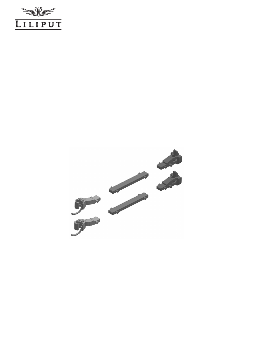
Kupplungsmöglichkeiten
Das Modell dieser Diesellok ist mit der Kupplungsaufnahme nach NEM 355 ausgestattet.
Im Blister finden Sie das Kupplungkopf-Set L42100-902-1 (Abbildung 5) bestehend aus
je zwei H0e-Standardkupplungsköpfen L949100 ohne Kupplungsbügel, zwei Mittelpufferkupplungen System Kadee L949120 und zwei Kuppelstangen L949112 für eine feste
Verbindung zwischen den Modellen untereinander. Wir schlagen vor, wenn Sie Ihre Lok in
Verbindung mit den Wagen des Pendlzuges betreiben, die Kuppelstange L949112 zwischen
Lok und Wagen montieren. Sie erhalten damit ein geschlossenes Zugbild und auch eine
störungsfreie Verbindung zwischen Lok und Wagen. Im Betrieb als Zuglok für Güterwagen
oder im Rangierdienst können Sie dann die Standardkupplung ohne Kupplungsbügel oder
die sogenannte Kadee-Kupplung montieren. Wichtiger Hinweis: durch die weit nach unten
gehende Pufferbohle ist die Funktion des Standard-Kupplungskopfes mit dem Kupplungsbügel nicht gewährleistet.
L949100
L949112
L949120
Abbildung 5 Picture 5
Coupling possibilities
The model of this diesel locomotive comes with a NEM 355 compatible coupling. The
blister pack contains the coupling head set L42100-902-1 (Picture 5) consisting of two H0e
standard coupling heads each L949100 without coupling bracket, two central buffer couplings Kadee L949120 and two coupling rods L949112 to ensure a firm connection between
the models. We suggest fitting the coupling rod L949112 between the locomotive and carriage if you wish to operate your locomotive in conjunction with the push-pull carriages. This
not only gives you a more cohesive looking train but also ensures interruption-free connection between locomotive and carriage. You can then fit the standard coupling without coupling bracket or the so-called Kadee coupling for operation as train locomotive for goods
trucks or for shunting work. Important information: The far reaching headstock means that
the function of the standard coupling head with coupling bracket is not guaranteed.
6

BACHMANN EUROPE PLC
1 2
3
ON
1 2
3
ON
1 2
3
ON
1 2
3
ON
Frontlichtsystem
Das Vorbild dieser Diesellok ist universell einsetzbar, im Strecken- oder im Rangierdienst.
Als Zuglok für Personen- oder Güterwagen. Dies erfordert je nach Verwendung auch ein
unterschiedliches Front- oder Schlußlicht. Im Verbund mit dem Wagen des Pendelzuges
soll immer nur die vom Zug abgewandte Frontseite
leuchten. Im Güterzugbetrieb nur immer die Vorderseite
der Lok mit weißem Spitzensignal. Diese verschiedenen
Möglichkeiten können Sie mit Hilfe eines eingebauten
Multischalters MS Abbildung 6 je nach Betriebsart
einstellen. Beachten Sie dazu das Schaltbild für den
Schalter in Abbildung 7. Im Auslieferungszustand hat Ihr
Modell den Lichtwechsel weiß / rot in beide Richtungen.
Zur Änderung heben Sie bitte durch Ausklippsen das
Lüfterteil L vom Lokdach ab. Nun haben Sie freien Zugang zum Multischalter.
Abbildung 6
Picture 6
MS 3 2 1
L
Grundeinstellung
Lichtwechsel weiß/rot
beidseitig
Lichtwechsel weiß/rot
Lightchanging white/red
ohne Spitzenlicht
without front light
Lichtwechsel weiß
beidseitig
Abbildung 7 Picture 7
Basic
Lightchanging white/red
both sides
ohne Spitzenlicht
without front light
Lichtwechsel weiß/rot
Lightchanging white/red
Lightchanging white
both sides
Front light system
The replica of this diesel locomotive can be universally employed for scheduled or shunting
services. As a locomotive for passenger or goods carriages a different front and rear light
are required depending on use. Only the front side facing away from the train should always
illuminate if used In conjunction with the carriage of the push-pull train. In goods train operation only the front side of the locomotive with white head light. These differing possibilities
can be set with the aid of the installed multiswitch MS Picture 6 depending on operation
type. Please pay attention to the circuit diagram for the switch in Picture 7. You model
comes with the light change white / red in both directions. To change this please remove
the locomotive top by unclicking the ventilator section L from the locomotive top. You now
have free access to the multiswitch.
7

BACHMANN EUROPE PLC
Umrüsten auf Digitalbetrieb
Bevor Sie umrüsten überzeugen Sie sich bitte, ob im analogen Gleichstrombetrieb alle
Funktionen in Ordnung sind. Die ersten Schritte zum Umrüsten wurden bereits mit Ab-
bildung 3 beschrieben. Nun können Sie den Brückenstecker entfernen und durch den
Decoder ersetzen. Beachten Sie bitte exakt die Einbauanleitung des Decoderherstellers. Zu
Fragen der Funktion und zum Einbau kontaktieren Sie bitte Ihren Lieferanten oder Hersteller
des Decoders. Wenn Sie eine Sounddecoder einbauen haben wir bereits einen Einbaurahmen H für den Lautsprecher eingebaut. Anschließen können Sie den Lausprecher mit zwei
Litzen an den mit SPK bezeichneten Pins. Sehen Sie dazu Abbildung 8.
H
SPK
DEC
SPK
Abbildung 8 Picture 8
Converting to digital operation
Before undertaking the conversion, please ensure that all functions run OK in analogue direct current operation. The first conversion steps have already been described in Picture 3.
You can now remove the jumper and replace with the decoder. Please make sure you follow
the installation instructions of the decoder manufacturer exactly. For questions regarding
function and installation, please contact your decoder supplier or manufacturer. If you wish
to install a sound decoder, we have already provided a fitting frame H for the loud speaker.
You can connect the loud speaker with two wires to the pins marked SPK. See Picture 8 for
details of this.
8

BACHMANN EUROPE PLC
R
L
N
C
1
N
C
11
NC
2
SPEAK2
1
0
N
C
3
SPEAK1
9
N
C
4
LEDF
8
N
C
5
LEDR
7
NC
6
N
C
12
N
C
1
3
AUX2
14
AUX1
1
5
LED+
1
6
NC
1
7
M
-
18
M
+
19
N
C
20
L
2
1
R
22
C
ON1
21PIN
D
2
S1
A
D
3
S1
A
R3
4
70OHM/12
10
R4
470 OHM/121
0
R2
2
20K/0805
R
1
220K/0
805
D
4
S1
A
D
1
S1
A
A
-
+
MOTOR1
L1
4.7
uH
L
2
4.7uH
C
2
0.1U
F/1
206
C
1
0.1U
F/1
206
SPEAK
ER
DI
ODE#
1011
9 x 6
L
ED8
W
R
12
1.5K/0805
C10
1
U
F/0
80
5
LED9
W
R
13
1.5K/0805
C11
1
U
F/0
80
5
L
E
D3
RED
R10
1.5
K/0
8
0
5
C
8
1UF/0805
L
ED4
R
ED
R
1
1
1.5K/
0
8
0
5
C
9
1UF/080
5
LE
D10
W
R
14
1.5K/080
5
C
1
2
1UF/
0
8
0
5
LED5
W
R
7
1
.5K/0805
C
5
1
U
F/0
80
5
LED7
W
R
6
1.5K/080
5
C
4
1UF/
0805
LE
D
1
RED
R
9
1.5K/
0
8
05
C
7
1UF/
0805
L
ED2
RE
D
R
8
1.5K/080
5
C6
1UF/
0
80
5
L
ED6
W
R
5
1.5K/
0
8
0
5
C
3
1UF/080
5
C13
0.1UF/100
V
C
14
0.1UF/100V
Q1
8550
K
1
6PI
N
R
15
1.5K/0805
R16
1.5K/0805
Q2
8550
D1
S1
A
D2
S1
A
NC
1
N
C
1
1
N
C
2
SPEAK2
10
NC
3
SPEAK
1
9
NC
4
LEDF
8
N
C
5
LEDR
7
NC
6
NC
12
NC
1
3
AUX2
14
AUX1
15
LED+
1
6
N
C
17
M-
18
M+
1
9
N
C
2
0
L
21
R
2
2
CON2
R
L
21 PinDCDummy Board
SHORTPAD
OPTIONAL
J1
J2
J
3
R1
7
1.5K/0805
D5
S1A
D
6
S1
A
1
#
2
#
3
#
R
e
ar
P
anel
LEDs
Fron
t
Pane
l
W
h
i
te
LEDs
Front
Panel
Red
LEDs
#1F
r
o
n
tAll
L
E
D
s
#2Re
ar
A
llLEDs
#
3Re
arRed LEDs
Schaltplan
Warranty Coupon
Should your LILIPUT model be faulty or not work properly or require repair, you can either
contact the dealer from whom you purchased the product or contact the customer services
department directly of one of the following addresses below.
Warranty Conditions:
This LILIPUT model has a warranty of two years from the
date of purchase on repairs and parts, as long as it was
purchased from an authorised dealer and if this certificate
has been stamped with the address of the dealership and
the date of purchase has been entered. The warranty
permits Bachmann Europe Plc either to rectify any fault or
to replace the faulty parts. Further claims are excluded.
Please note that no liability can be assumed for any parts
subsequently fitted or for any damage caused thereby.
GREAT BRITAIN
AND ALL OTHER COUNTRIES
( EXEPT GERMAN SPEAKING COUNTRIES )
9
BACHMANN EUROPE PLC
MOAT WAY, BARWELL
GB - LEICESTERSHIRE LE9 8EY
Circuit Diagramm

BACHMANN EUROPE PLC
Garantie-Schein
Sollte Ihr LILIPUT-Modell einen Mangel oder eine Störung aufweisen oder einmal reparatur-bedürftig sein, haben Sie die Möglichkeit, sich diesbezüglich entweder an den Händler,
bei dem Sie das Produkt gekauft haben oder direkt an die Kundendienstabteilung einer der
nachfolgend angegebenen Adressen zu wenden.
DEUTSCHLAND:
BACHMANN EUROPE PLC
NIEDERLASSUNG DEUTSCHLAND
AM UMSPANNWERK 5
D - 90518 ALTDORF BEI NÜRNBERG
ÖSTERREICH:
DOLISCHO MODELLSPIELWAREN
BAHNSTRASSE 4
A - 2340 MÖDLING
Garantiebedingungen:
Dieses LILIPUT-Modell hat ab Kaufdatum zwei Jahre
Garantie auf Reparaturen und Teile, sofern es bei einem
autorisierten Händler gekauft wurde und dieses Zertifikat
vom Händler abgestempelt und das Kaufdatum eingetragen worden ist. Die Garantie umfasst nach Wahl von
Bachmann Europe Plc entweder die Beseitigung eines
eventuellen Mangels oder den Ersatz schadhafter Teile.
Weitergehende Ansprüche sind ausgeschlossen.
Beachten Sie bitte, dass für nachträglich eingebaute Teile
sowie für dadurch entstandene Schäden keine Haftung
übernommen wird.
Wichtig! Wir empfehlen die Originalverpackung aufzubewahren,
sie ist der beste Schutz für Ihr Modell, wenn dieses nicht gerade
auf Ihrer Anlage unterwegs ist. Beim Betrieb der Lok auf Teppichböden kann die feine Mechanik durch Fasern zerstört werden.
Änderungen in Konstruktion und Ausführung vorbehalten. Bitte
bewahren Sie diese Beschreibung zum späteren Gebrauch auf.
Dieses Produkt wurde nach Vorschriften der europäischen Spielzeugrichtlinien (CE) hergestellt. · Important! We recommend that
you keep the original box. It is the best place to store your model,
when it is not in use. Please be aware, that carpet fibres can destroy the fine mechanism of the locomotive. Subject to changes
in design, version and technical data. Please retain these data
and instructions for further reference. This product has been manufactured according to the European toy Safety Directive (CE).
Importante! Raccomandiamo di tenere la scatola
originale. E’ il posto migliore in cui tenere il tuo modello quando non è in uso. Fibre di tappeti possono
distruggere il fine meccanismo della locomotiva.
Preghiamo di conservare questi dati ed istruzioni per
SCHWEIZ:
MODELLBAU UND
ELEKTRONIK
STETTBACHSTRASSE 193
CH - 8051 ZÜRICH
ALLE ANDEREN LÄNDER:
BACHMANN EUROPE PLC
MOAT WAY, BARWELL
GB - LEICESTERSHIRE LE9 8EY
Kaufdatum mit Händlerstempel
altre informazioni. Quest’articolo è stato prodotto in accordo con
la Direttiva Europea Sicurezza giochi (CE).
Achtung! Bei unsachmäßigem Gebrauch besteht Verletzungsgefahr durch funktionsbedingte scharfe Kanten und Spitzen • Atten-
tion! At an incorrect use there exists danger of hurting becauseof
cutting edges and tips • Attention! Il y a danger de blessure à
un emploi incorrect à cause des aiguilles et arêtes vives! • Voor-
zichtig! Bij ondoelmatig gebruik bestaat verwondigsgevaar door
scherpe zijkanten en uitsteeksels! • Attenzione! Un uso improprio
comporta pericolo di ferimenti attraverso punte e spigoli taglienti!
• Atencion! Un empleo incorrecto puede causar heridas debido a
las puntas y aristas agudas! • Atençao! Por utilizaçao incorrecta
existe o perigo de estragos, em virtude de cortes nas abas e nas
pontas! • Προξοχη! Η ακαταλληλη χρηοη εγκλειει
κινδυνουζ μκροτ ραυματιομων, εξ αιπαξ κοπτερων
ακμων και προεξοχωθν • Bemaerk! Ved ukorrekt
brug kan de funktionsbetingede skarpe kanter og
spidser forfolde skade!
BACHMANN EUROPE Plc · Moat Way · Barwell · Leicestershire · LE9 8EY England Made in China
10
1010
 Loading...