


BACHMANN EUROPE PLC
Betriebsanleitung D / GB / F
L133940 - 59
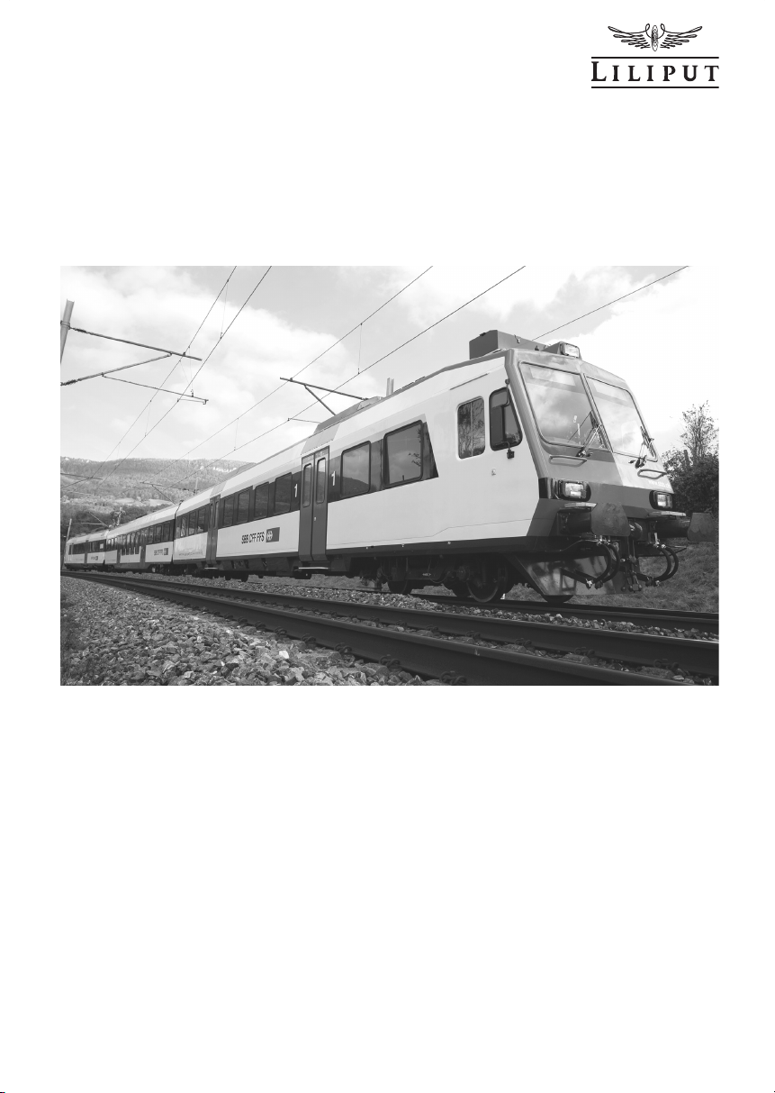
Nahverkehrs-Pendelzug, Typ DOMINO der SBB-CFF
Die heutigen NPZ (Nahverkehrs-Pendelzüge) waren seit rund 30 Jahren im Einsatz.
Sie mussten deshalb an die gestiegenen Bedürfnisse der Bahnkundinnen und
-kunden angepasst werden.
Die SBB modernisierte 120 Triebwagen (RBDe 560/561) im Industriewerk Yverdon
und 121 Steuerwagen (Bt NPZ) im Industrie
werk Olten. Die Fahrzeuge wurden
bis auf den Wagenkasten zerlegt und anschliessend wieder aufgebaut. Einzig die
alten Zwischenwagen der Typen EW I und EW II tauschte die SBB mit 140 neuen
Niederflurzwischenwagen „Inova“ der Firma Bombardier aus. Alle drei Komponenten bilden zusammen die neuen Regionalverkehrszüge „Domino“, die auf bis zu
vier Zwischenwagen erweitert werden können.
Die Züge bieten klimatisierte Fahrgasträume, Niederflureinstieg für bequemes
Ein- und Aussteigen, behindertengerechte Ausstattung, Kundeninformation via
Monitor und mehr Sicherheit durch Videoüberwachung. Die neuen Züge verkehren im neuen SBB Design, als Glarner Sprinter und als RegionAlps.

BACHMANN EUROPE PLC
2 H0 1:87
Vorbereiten Ihres Modells
Nehmen Sie bitte vorsichtig die einzelnen Einheiten aus dem Blister. Die Einheiten A und
B sind mit je einen Motor ausgestattet. Aber nur Einheit A (mit Pantograph) (Abb.1) kann
zu Testzwecken einzeln gefahren werden. Einheit B fährt nur im Verbund mit den anderen
Einheiten.
Kuppeln der Einheiten
Die Modelle sind mit stromführenden Spezialkupplungen ausgerüstet. Stellen Sie denTriebwagen Einheit A (mit Pantograph) und den Zwischenwagen Einheit C mit etwas Abstand
auf das Gleis. Achten Sie generell bei den Kuppeln zweier Einheiten immer darauf, dass
sich zwei ungleiche Kupplungsteile (mit und ohne Haltenase) (H ) nach ( Abb. 2) gegenüberstehen.
Schieben Sie nun vorsichtig die Einheiten bis zum Berühren der Kupplungen zueinander.
Wir empfehlen die beiden
Wagen-Enden leicht (ca.
2 cm) von der Schiene zu
heben und die Haltenase (H )
gemäß (Abb. 2 a ) auf einen
Finger aufliegen zu lassen.
Dadurch können die beiden
Kupplungsteile, ohne nach
unten abzuknicken, mit
leichten Druck ineinander
geschoben werden bis die
Haltenase einrastet.
Zum Kuppeln des Steuerwagens Einheit B an dem
Zwischenwagen Einheit C
wiederholen Sie sinngemäß
diesen Vorgang.
Abbildung 1
Abbildung 2
Abbildung 2a
H
H
Liliput wünscht Ihnen viel Freude mit Ihrem DOMINO-Modell
Einheit B Einheit C Einheit A

BACHMANN EUROPE PLC
H0 1:87 3
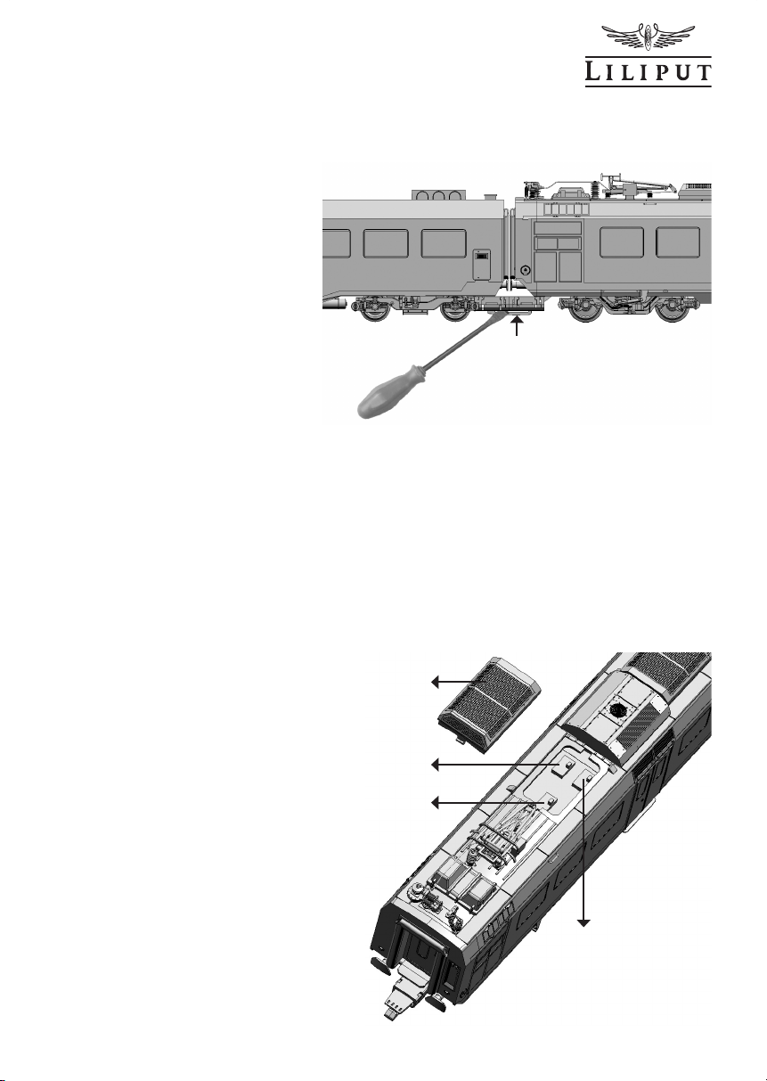
Entkuppeln der Einheiten
Zum Entkuppeln (Abb. 2b) drükken Sie bitte die Haltenase ( H )
mit einem Schraubendreher von
der Seite nach unten und ziehen
dann die Einheiten auseinander.
Das 3-teilige Grundmodell des
DOMINOS kann auch mit den
erhältlichen Zwischenwagenset
Einheiten D, E ... vorbildgerecht
zu einem mehrteiligen Triebzug
erweitert werden.
Die Anordnung der Zwischenwagen im Triebzug ist wie beim Vorbild frei wählbar. Ein vorbildwidriges Verdrehen einer
Einheit im Verband ist durch die jeweilige Kupplungspaaranordnung ausgeschlossen.
Inbetriebnahme Ihres Gleichstrom-Modells ( DC )
Wenn das Kuppeln der Einheiten
abgeschlossen ist, ist der Triebzug fahrbereit.
Das Gleichstrom-Modell ist in
der Grundeinstellung so geschaltet, dass die Stromabnahme über alle Räder der beiden
Endwagen erfolgt.
Wenn Sie an der Grundeinstellung etwas ändern möchten,
können Sie dies wie folgt tun:
Drei Schalter befinden sich
dazu auf der Hauptplatine direkt
unter dem Dach der Einheit A.
Zum Bedienen dieser Schalter
müssen Sie die kleine Widerstandsabdeckung (W ) nach
oben abziehen (Abb.3 ).
H
S1
S3
S2
W
Abbildung 2b
Abbildung 3

BACHMANN EUROPE PLC
4 H0 1:87
Wenn Sie im Blockstreckenbetrieb fahren
oder in einem Sackbahnhof automatisch
stoppen wollen, so schalten Sie bitte den
Schalter S3 (Abb. 3 a ) auf Stop-Funktion.
Mit dem Schalter S2 können Sie wahlweise über Radkontakt oder Oberleitung
die Stromabnahme wählen. Im Oberleitungsbetrieb mit dem Pantographen ist
die Stop-Funktion aber nicht möglich. Die
eingebaute LED-Innenbeleuchtung ist in
der Grundeinstellung eingeschaltet.
Mit dem Schalter S1 schalten Sie die
Innenbeleuchtung wahlweise aus oder ein.
Im Digitalbetrieb muss dieser Schalter auf
„aus“ stehen. Die Innenbeleuchtung wird
hier mit dem Decoder ein- bzw. ausgeschaltet.
Einbau eines DCC-Decoders
Das Modell des FLIRT hat eine 21 + 2-polige Decoderschnittstelle (D ). Die eingebaute Schnittstellen-Platine trägt die Schaltung
für die Stop-Funktion. Wenn Sie auf
Digitalbetrieb durch Einbau eines Decoders
umstellen, so ist die Stop-Funktion ausser
Betrieb.
Zum Einbau eines Decoders müssen Sie
das Gehäuse der Einheit A nicht demontieren. Die Schnittstelle befindet sich vor den
Einstiegstüren auf der oberen Platine direkt
unter der großen Widerstandsabdeckung
(G ). Dieses Teil wird mit zwei Schnappnasen gehalten und lässt sich nach oben
abheben ( Abb.4 ).
S3
S2
S1
DCC DC
S1
S2
S3
Abbildung 3a
Abbildung 4
G
D
BACHMANN EUROPE PLC
H0 1:87 5
Einbau eines Lautsprechers
Der Triebwagen ist bereits für den Loksoundbetrieb komplett vorbereitet. Den
Sound-Decoder können Sie auf der 21poligen Schnittstelle senkrecht aufstecken.
Dazu folgen Sie bitte der Beschreibung
unter „Einbau eines Decoders“ im Kapitel
vorher.
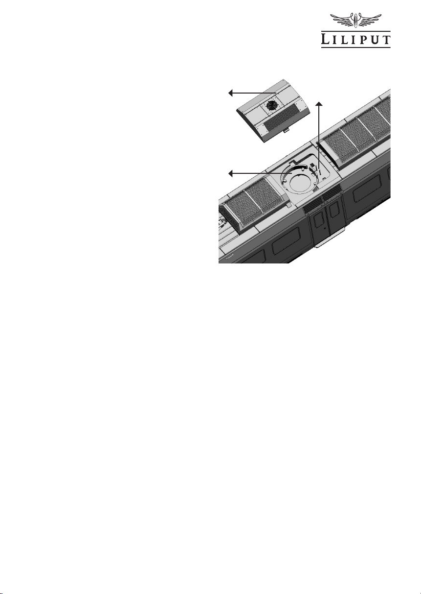
Der Einbauraum des Lautsprechers
(Abb. 5 ) ist im Dachbereich unter der
Klimagerätabdeckung ( K ) vorgesehen.
Dieses Teil ist am Dach nur leicht klemmend angesteckt. Sie können das Klimagerät leicht vom Dach lösen und senkrecht
abziehen. Der Lautsprecher (d = 16 mm)
kann in das Montageteil ( M ) eingeklipst
werden. Den Lautsprecher selbst können
Sie an zwei auf der Leiterplatte verlöteten
Stifte (V ) anschliessen.
Wartung und Pflege Ihres Modells
Um eine lange Lebensdauer zu gewährleisten sollte der Triebwagen in regelmässigen Abständen gewartet werden. Das Modell muss dazu nicht geöffnet werden. Vielmehr genügt
es wie nach ( Abb. 6 ) das Modell auf einer weichen Unterlage auf das Dach zu legen, ohne
dabei Dachaufsteckteile oder den Pantographen zu beschädigen. Mit einem in Spiritus
getränkten Wattestäbchen säubern Sie die Radkontakte, danach reinigen Sie die Räder.
Drehen Sie dabei bitte auf keinen Fall die Antriebsräder von Hand durch.
Nach dem Reinigen schmieren Sie bitte die in der Abbildung bezeichneten Lagerstellen
( L) mit einem Tropfen Maschinenöl. Sinnvoll ist es, diese Wartungsarbeiten nach ca. 30-40
Stunden Betriebszeit durchzuführen.
Abbildung 5
K
M
V
Abbildung 6 siehe nächste Seite

BACHMANN EUROPE PLC
6 H0 1:87
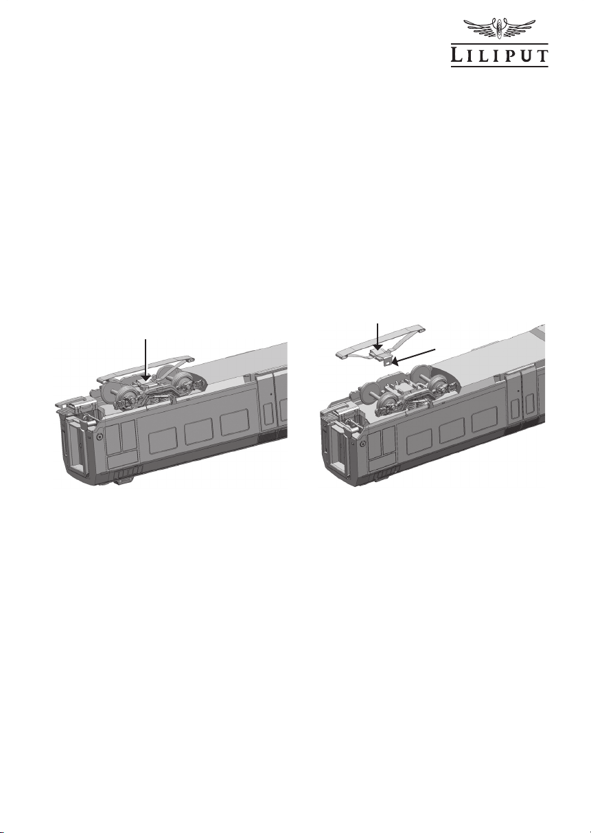
Auch zum Schmieren der Getriebeteile muss
der Triebwagen nicht geöffnet werden. Vielmehr genügt es, das Motor-Drehgestell nach
einer Seite wie in (Abb.7) dargestellt, zu verschwenken. Danach können Sie zwischen
Drehgestell und Fahrgestell hindurch auf Schnecke und Schneckenrad ( O ) sehen und mit
einer Pipette die kompletten Getriebeteile ( Z ) ölen. Fahren Sie danach mit dem Triebwagen etwas vor und zurück. So verteilt sich das Öl gleichmässig. Verwenden Sie handelsübliche Öler mit feiner Kanüle oder einer Stecknadel. Achtung, kein Speiseöl oder Hautcreme
verwenden.
Öffnen der Fahrzeuge
Das Öffnen der Fahrzeuge zum Beispiel zum Ausstatten mit Fahrgästen wird wie folgt
ausgeführt:
Ziehen Sie bitte mit beiden Daumennägeln im hinteren Türbereich (T ) gemäß ( Abb.6 ) den
Wagenkasten etwas auseinander und drücken dabei mit leichten Druck der Zeigefinger auf
die hinteren Pufferteller (P) den Wagenkasten und Fahrgestell voneinander weg.
LL
L
LL
L
L
T
Abbildung 6
P
P
T
Abbildung 7
ZZZZ Z
O
L
Z
BACHMANN EUROPE PLC
H0 1:87 7
Ihr Modell in Wechselstrom-Ausführung
Wenn Sie sich für ein LILIPUT-Modell mit Mittelleiter-Wechselstrom-System entschieden
haben, beachten Sie bitte Folgendes: Dieses Modell verfügt über einen eingebauten Digitaldecoder ( ESU-Lokpilot ), mit dem Sie wahlweise Ihr Fahrzeug analog ( 16 Volt Wechselstrom ) oder digital betreiben können. Über die Funktionsweise des Decoders informiert
Sie die beigefügte Betriebsanleitung der Firma ESU. Zur Stromaufnahme vom SchienenMittelleiter ist je ein Schleifer am Laufdrehgestell der Endeinheiten eingebaut. ( Abb.8 )
zeigt den eingebauten Schleifer, in ( Abb.9 ) sehen Sie den ausgebauten Schleifer mit dem
Haltebügel ( R ). Beim Einbau schnappt der Haltebügel einfach in zwei Haltenasen. Beim
Demontieren drücken Sie bitte den Haltearm ( S ) leicht mit einem kleinen Schraubendreher nach aussen. Selbstverständlich wurde auch das Radprofil der Radsätze dem üblicherweise verwendeten Gleissystem angepasst.
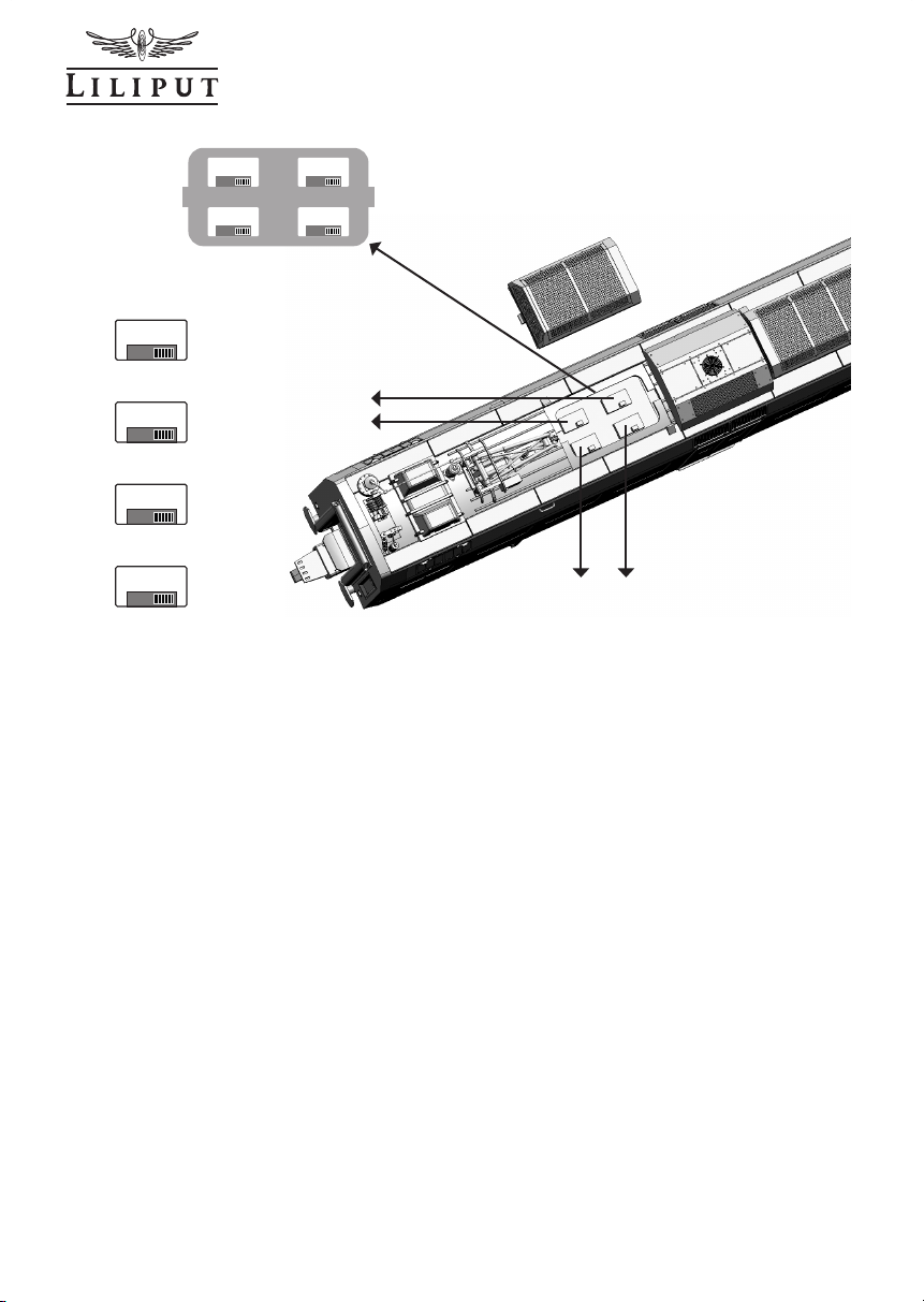
Die Wechselstrom-Ausführung hat in der Wageneinheit A im Dachbereich eine Platine
mit vier Schaltern. ( Abb.10 ) zeigt die Lage der einzelnen Schalter sowie die Stellung der
Einstellpositionen A oder B. Im Auslieferungszustand befinden sich alle vier Schalter in
Position A. Für die Stop-Funktion schieben Sie bitte Schalter S3 und S4 in Position B. Im
Oberleitungsbetrieb mit dem Pantographen ( S2 in Position B ) ist die Stop-Funktion aber
nicht möglich. Im Digitalbetrieb muss S1 auf Position B stehen. Die Innenbeleuchtung wird
hier mit dem Decoder ein- bzw. ausgeschaltet.
Abbildung 8 Abbildung 9
R
S
R
Abbildung 10 siehe nächste Seite

BACHMANN EUROPE PLC
8 H0 1:87
Beachten Sie bitte, dass die Funktionsausgänge am Decoder AUX3 und AUX4 die folgenden CV-Einstellungen haben müssen:
Decoder-Typ V3.0: CV117 = 15, CV118 = 15, CV129 = 32, CV132 = 16, CV135 = 32,
CV138 = 16
Decoder-Typ V4.0: CV013 = 009, CV049 = 017, CV052 = 016, CV266 = 032, CV282 = 016,
CV298 = 032, CV314 = 016
In dem von uns eingebauten Decoder wurden bereits diese Einstellungen vorgenommen.
Alle anderen Bedienpunkte lesen Sie bitte weiter vorn unter Kuppeln der Einheiten, Inbetriebnahme oder Wartung und Pflege Ihres Modells nach.
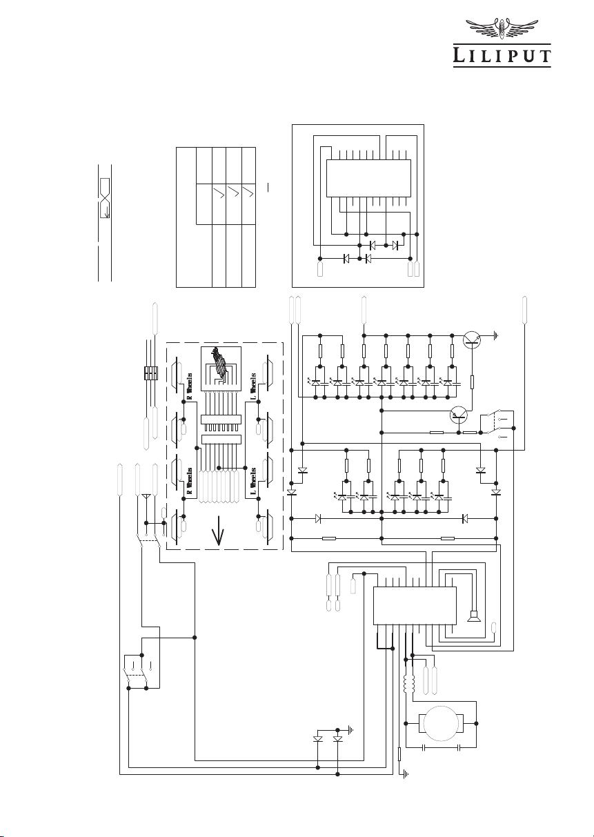
Schaltpläne
Für alle, die sich noch mehr vertiefen wollen, haben wir hier im Anschluss die kompletten
Schaltpläne für die Wageneinheiten und Stromsysteme abgebildet.
Abbildung 11 (Seite 9) zeigt das Schaltbild der Wageneinheit A in der Gleichstromversion (DC), Abbildung 12 (Seite 10) in der Wechselstromversion (AC). Das Schaltbild für
Wageneinheit B in beiden Stromsystemen (DC und AC) zeigt Abbildung 13 (Seite 11).
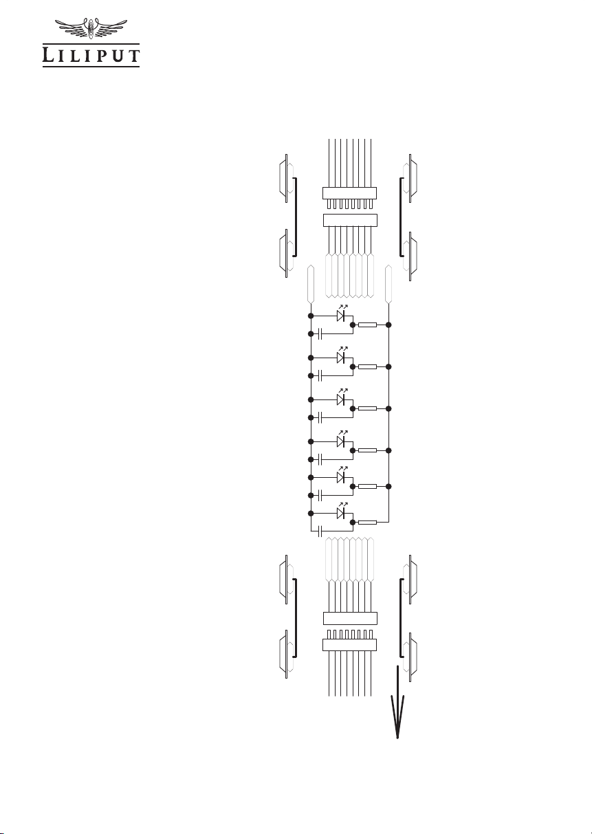
Das Schaltbild der Zwischenwageneinheiten C, D, E ... ist in allen Versionen gleich, siehe
Abbildung 14 (Seite 12).
S1
S2
S3
S4
S3
S4
B A
B A
B A
B A
S2
S1
S1
S3
S4 S2
Abbildung 10
BACHMANN EUROPE PLC
H0 1:87 9
I
n
t
e
ri
or
L
i
g
h
t
X
5
R
e
a
r
Light
X
2
F
r
o
n
t
Li
g
ht
X
2
L1
4.7uH
L2
4.7u
H
C1
0
2
10
4
C1
01
10
4
L
ED
1
R
C11
05
L
E
D2R
C210
5
R
1
2K
R22K
R
1
4
22
0
K
R1
3
220
K
SPK
1
1
2
2
MOTOR
L
ED3W
LE
D
4
W
C4105
C
31
05
R
3
2
K
R
4
2K
LE
D
6
Y
LE
D
7
Y
R
6
2
K
R
7
2K
LE
D1
1
Y
LE
D
8
Y
L
E
D9Y
LE
D
10
Y
R
8
2K
R92
K
R
10
2K
R
11
2
K
N
C
1
N
C
2
N
C
3
A
UX 4
4
N
C
5
NC
6
LEDR
7
LEDF
8
S
PEA
K
1
9
S
P
EAK
2
1
0
N
C
11
R
2
2
L
21
N
C
2
0
M
+
1
9
M
-
1
8
N
C
17
LED+
16
AU
X
1
1
5
AUX214A
U
X
3
1
3
NC
1
2
R
(3
/7
)
A
L(
4/8)
B
CO
N2
CON
N
E
#
10
4
40(23PIN)
S
ta
t
i
on
n
a
me
X
2
Ri
gh
t
Wh
eel
Rea
r P
i
ck
-u
p
Un
i
t
A
A
U
X
3
AU
X
4
A
DC
P
i
c
k u
p
S2A
2
3
P
i
n
DCC Du
m
m
y
Bo
a
r
d
N
C
1
N
C
2
N
C
3
N
C
4NC5
N
C
6
LEDR
7
L
ED
F
8
S
P
E
AK
1
9
S
P
EAK2
10NC11
R
2
2
L
2
1
N
C
2
0
M
+
19
M
-
18
N
C
1
7
LE
D
+
16
A
U
X
I
1
5
AU
X2
1
4
NC
1
3
NC
1
2
R
(
3
/
7
)
A
L(
4
/8
)
B
CON1
CO
NN
E#
10
4
4
1
(26
P
IN
)
D
2
S1
A
D1S1
A
A
L
R
C
O
N
1
-
2
2
P
I
N
C
O
N1
-
2
1
P
IN
S
W
I
T
C
HES
R
L
R
L
STOP
R
(
F
) R
(R
)
+
- -
SW3
B
B
A
A
P
I
CK
-
U
P
R
0
0O
H
M
C
6
10
5
C
7
10
5
C
8
10
5
C
9
1
0
5
C
1
010
5
C
1
110
5
LED5
W
C5
105
R52K
B
+
F
LIG
H
T
-
MOT
-
M
OT+
LD1
LD2
LD3
L
D
4
LD5
LD6
LD7
L
D8
L
D
9
L
D
10
L
D11
R
R(R)
R(F)
P
ad
A
UX
3
P
a
d
A
UX
4
1
2
3
4
5
6
7
8
C
O
N
5
C
ON
N
E
#
1
0
3
4
5
1
2
3
4
5
6
7
8
C
O
N
15
C
O
N
N
E
#
1
0
3
4
4
R W
h
eel
3
R W
h
e
e
l
3
LW
h
eel
4
LWh
e
el
4
Tr
a
c
k
Ri
g
ht
Tr
a
c
k
L
e
f
t
Fron
t
L
ight
I
nte
r
ior
l
ig
h
t
B
+
Rear
Li
gh
t
M
o
t
o
r
Output-
M
o
tor O
u
tp
u
t+
R W
h
e
e
l
1
R
Wh
ee
l
1
L
Whe
e
l
2
L
W
h
e
e
l
2
SW2
P
a
n
to
g
r
aph
F
ront Tra
c
k Rig
h
t
RearTra
ckR
ight
Tra
c
k Le
f
t
F
ront L
i
gh
t
I
n
te
r
i
o
r
l
ig
h
t
B
+
R
earL
i
gh
t
M
o
tor O
u
tp
u
t-
M
oto
r
Out
p
ut+
F
ro
n
t T
r
a
c
k Rig
h
t
P
A
N
RRear
RFront
DC
Pa
d
Fron
tT
r
ac
k
Rig
h
t
Pa
d
F
r
ontTra
c
kL
e
ft
Pad
Re
ar
T
r
a
c
k
Ri
g
h
t
Pad
Rea
r
TrackLeft
P
a
d
PAN
A
A
B
B
LE
D1
2
Y
R
12
2K
C
1
210
5
LD12
Big
L
ightX
1
Q
3
8
5
50
Q48
0
50
D7 RGL3
4A
D
9
R
GL34A
R201
0
0
K
R2
2
2
K
R
2
1
4
.7
K
D8
RGL3
4A
D10
RGL34
A
D
5
RG
L
34A
D
6
R
GL34
A
AUX1
Pad
AU
X
2
T
r
a
c
k
R
ig
h
t
3
r
dr
a
i
lt
r
a
c
kO
p
e
n
Front
T
r
a
ck
R
igh
t
Re
a
rT
r
a
c
kR
i
g
h
t
2r
a
i
l
tr
a
c
kS
h
o
r
t
T
r
ackL
e
f
t
S
HO
R
T
A
C
-
TO
-
D
C
T
r
ac
k
Ri
g
h
t
T
r
ac
k
L
e
f
t
F
r
o
n
t
T
r
ack
R
ig
h
t
SW1
D3
S1
A
D4
S1
A
A
B
B
A
ON
OFF
1
2
3
4
5
6
D
11
S
1
A
D
12
S
1
A
1
2
3
4
5
6 1
2
345
6
L
ef
t
Wh
e
els ALL
R LIGHT-
1
234
5
6
7
8
J
P
1
5
C
o
n
n
ect
or
F
LE
D
-
RLE
D
-
L
AL
L
B
+
MO
T
-
MO
T
+
I
L
E
D
-
RR
e
ar
F
LE
D
-
RL
E
D
-
L
A
L
L
B
+
M
O
T
-
MO
T
+
I
L
ED
-
RRear
S
W
2
I
n
t
er
i
o
r
L
i
gh
t
S
W
1
ST
O
P
F
u
n
c
ti
o
n
S
W
3
A
B
O
N O
F
F
P
A
N
TO
T
R
AC
K
S
witch
e
s N
o
r
m
al
s
et
t
o
A
p
o
si
t
i
o
n
S
T
O
P
C
O
N
NE
C
T
A
L
L
Wh
e
e
l
s
F
ro
nt
Powe
r
G
R
A
P
H
Abbildung 11 Figure 11 Illustration 11

BACHMANN EUROPE PLC
10 H0 1:87
In
t
er
i
o
r
L
igh
t
X
5
R
ea
r Li
g
ht
X
2
F
ro
n
t
Li
g
ht
X
2
L
1
4.7u
H
L
2
4.7u
H
C
1
02
10
4
C
10
1
10
4
LE
D
1
R
C1
1
0
5
LE
D
2
R
C
21
0
5
R
1
2KR
2
2
K
R
1
4
2
2
0K
R
13
2
2
0
K
SPK
1
1
2
2
+
MOT
OR
LE
D
3
W
L
E
D
4
W
C
4
10
5
C
31
0
5
R32KR
4
2
K
LED6
Y
L
E
D
7Y
R6
2
K
R7
2K
LE
D
11Y
L
ED8
Y
L
E
D
9Y
L
E
D
10
Y
R
8
2K
R92KR10
2KR11
2K
D16
R
G
L34
A
NC1NC2N
C
3
A
U
X
4
4
N
C
5
N
C
6
LEDR
7
L
ED
F
8
S
PEAK
1
9
S
PE
A
K2
1
0
N
C
1
1
R
2
2
L
2
1
N
C
2
0
M+
1
9
M-
1
8
N
C
1
7
LE
D
+
1
6
AU
X
1
1
5
A
U
X
2
1
4
A
U
X
3
1
3
N
C
1
2
R
(
3
/
7
)
A
L
(
4
/
8
)
B
C
ON
2
C
ON
N
E
#
10
44
0(
23
PI
N)
S
t
atio
n
n
a
me X 2
+
EC
1
10UF/35V
Unit A
V
+
A
U
X
3
A
U
X
4
D1
5
RGL34
A
R
1
8
1
0K
R
16
10
K
Q1
80
5
0
D
Q2
8
05
0
D
C
14
1
0
4
C
15
10
4
R1
5
10
0
K
R
1
7
100
K
A
U
X
3
A
U
X
4
R1
9
220
A
AC
C
1
3
104
SW3
SW4
R
0
0
O
H
M
C6
10
5
C71
0
5
C
8
105
C
9
105
C10
1
0
5
C11105
L
E
D
5
W
C
51
0
5
R
5
2
K
B
+
FL
I
GH
T
-
M
O
T
-
MO
T+
LD
1
L
D2
L
D
3
LD4
L
D5
LD6
LD7
LD8
LD9
L
D
1
0
L
D11
R
R
(R)
R(
F)
Pad
A
UX
3
P
ad
A
UX
4
SW
2
Pa
n
t
o
g
r
a
ph
F
r
o
n
t
Tr
ack
Ri
g
h
t
T
r
a
ck
R
ig
h
t
T
r
a
ck
L
ef
t
Fr
o
nt Light
I
nt
eriorl
i
ght
B
+
R
ear
L
i
gh
t
M
o
t
or O
u
t
p
u
t
-
Mo
t
or Ou
t
pu
t
+
P
AN
RR
ea
r
RFr
ont
Pad
PANTO
G
R
A
P
H
D
13
RG
L
3
4
A
D14
RGL3
4A
D
1
1
R
GL3
4
A
D
12
RGL34A
DIA
5
X7
LED12Y
R
1
2
2K
C12
1
05
LD1
2
Bi
g
Light
X
1
Q38
550
Q48
0
50
D7
R
GL34
A
D
9
RG
L
3
4
A
R20
10
0K
R
2
2
2K
R21
4.7K
D
8
RGL3
4A
D
1
0
R
GL3
4
A
D
5
RGL34
A
D
6
RG
L
3
4
A
A
UX1
P
ad
AUX2
SW
1
ON
OFF
3
2
4
8
9
7
10
6 5
1
COIL1
COIL2
K
1
ME-12-L2-12-RELAY
RLI
G
HT-
L
A
LL
ABB
A
1
2
345
6
ABB
A
1
2
3
4
5
6
A
B
B
A
1
2
3
4
5
6
A
B
B
A
1
2
345
6
Pad
Fr
on
t
T
r
ack
R
ig
h
t
Pad
F
rontTr
a
ckLe
f
t
P
ad
A
C
Tr
a
ck
1
2
3
4
5
6
7
8
CO
N1
5
CONNE#10511
1
2
3
4
5
6
7
8
CON
8
CONNE#10510
R
F
r
ont
F
L
ED
-
RL
ED
-
LA
L
L
B+
M
O
T-
MOT+
I
L
E
D
-
R
W
hee
l
3
R W
heel
3
L
Wheel
4
LWh
e
el
4
TrackRig
h
t
T
rac
k L
ef
t
F
ro
nt L
i
g
h
t
In
t
eriorlight
B
+
R
ea
r Li
g
ht
MotorOut
p
ut-
MotorOutput+
R
W
hee
l
1
R W
heel
1
L
Wheel
2
L
Wheel
2
Fr
o
n
t T
rac
k Ri
g
ht
A
C
R
Rear
Pad
R
ear
T
ra
c
k
R
ight
Pad
R
ea
rT
ra
c
k
L
ef
t
12345
6
7
8
J
P
1
5
D3
35
4
FLE
D
-
R
L
ED
-
L
AL
L
B
+
MOT
-
MOT+
I
L
ED-
RRear
SWI
T
CHES
PICK
-
UP
SW2
In
t
erior
L
ig
h
t
S
W
1
STO
P
Functi
o
n
S
W3
A
B
O
N OFF
PANTO
TRACK
S
wi
tches Nor
m
al set to A
p
o
s
ition
S
TOP
CONNE
C
T
A
LL
Wh
e
e
ls
Po
w
e
r
GR
AP
H
ST
OP
Fu
n
c
ti
o
n
S
W
4
STOP
C
ON
N
EC
T
ALL
Whe
els
R
L
R
L
ST
O
P
R(F
) R
(R
)
+
- -
Abbildung 12 Figure 12 Illustration 12

BACHMANN EUROPE PLC
H0 1:87 11
LED13
Y
R
25
2K
LED14
Y
R
26
2K
LED15
Y
R
27
2
K
LED16
Y
R
28
2K
LED3A
W
R2
9
2K
LED4A
W
R3
0
2K
LED5A
W
R3
1
4.7K
LED1A
R
R
23
2K
LED2A
R
R24
2K
LED6A
Y
R3
2
2K
LED7A
Y
R3
3
2K
C
2
3
105
C1
7
105
C27
10
5
C21
105
L1
22u
H
L2
2
2uH
C02
1
0
4
C
0
1
1
04
Rea
r L
i
g
h
t
x
2
Fr
o
n
t
Lig
h
t x 2
I
n
terio
r
Lig
h
t x 5
S
t
ati
o
n
n
ame L
E
D X
2
Rear Light
Front Light
Interior Light
Rear Light
Front Light
Un
it B (
D
C , AC )
C161
0
5
C
2
4
10
5
C
2
5
105
D
1
6
R
G
L3
4A
D
1
5
R
G
L34
A
B
+
M
- M+
C
1
8
10
5
C19
10
5
C20105
C26
105
FLED-
RLED-
B+
MOT-
MOT+
ILED-
FLED-
RLED-
Front Light
Interior light
B+
Rear Light
Motor Output-
Motor Output+
Front Light
Rear Light
S
2
A
Pa
d Fro
nt
T
ra
ckRigh
t
Pad Fr
o
nt
T
rac
kL
ef
t
P
a
d
AC
T
rack
123
4
567
8
JP
1
5
D
3
3
54
1234567
8
C
O
N
8
CO
N
N
E#
1
0
3
4
5
1234567
8
CON1
5
CO
N
N
E#
1
0
3
4
4
R
W
h
eel
7
R
W
h
eel
7
LWh
e
el
7
LW
h
eel
7
L
e
f
t Re
a
r
Wh
e
e
l
s
T
rack
R
ig
h
t
T
r
a
ck
L
ef
t
F
r
o
n
t
L
i
g
h
t
Int
er
i
o
r
l
ig
h
t
B+R
earL
i
g
h
t
M
o
to
r
Out
p
u
t
-
M
ot
o
r
O
ut
p
u
t
+
R
i
g
h
t
R
e
ar Wh
ee
l
s
R
W
h
eel
5
R
W
h
eel
5
LWheel
8
LWheel
8
L
e
ft
F
ro
nt
W
hee
l
s
R
i
gh
t
Fron
t
Wh
e
els
S
2
A
123
4
567
8
JP
1
5
D
3354
1234567
8
CON8
C
ONNE#
1
03
45
12345
6
7
8
CON15
C
ONNE
#10
3
44
R
W
h
ee
l
6
R Wheel
6
LWheel
6
LWheel
6
T
r
ack
R
ight
T
r
ackLeft
F
ro
n
t
Lig
h
t
Inter
i
orlight
B+
RearLight
MotorOutput-
MotorOu
t
pu
t
+
R Wheel
5
R
W
he
el
5
LWheel
8
L
Whee
l
8
A
C
D
C
/
D
CC
P
a
d Fr
on
t
T
r
a
ck
R
i
g
h
t
P
a
d
F
r
o
n
t
Tr
a
ck
L
e
f
t
P
ad RearT
r
a
ck
R
i
g
h
t
P
ad
Rea
r
T
r
ack
L
e
f
t
Pa
d
Rear
T
rac
k
Right
P
a
d
Rear
Tr
ac
k
L
ef
t
B+
M
OT+
LD1L
D
2
L
D
3
R
F
ron
t
1
2
3
456
J
P1A
1
2
345
6
JP1
B
+
M
O
T
+
L
D1
LD
2
LD3
RFront
1
2
345
6
C
ON9
CO
N
N
E#
1
0
3
9
0
B
+
M
OT
+
LD1
LD2
LD3
RFr
on
t
1
2
3
456
CO
N
7
C
O
N
N
E#
1
0
4
0
4
1
23456
J
P
1
A
1
23456
J
P
1
1
23456
C
O
N
1
0
C
O
NN
E#
1
0
390
1
2
345
6
C
O
N
6
C
O
N
N
E
#
1
0
4
0
4
M
OT-
L
D
4
LFront
M
O
T-
LD4L
F
r
on
t
M
O
T
-
L
D
4
LFron
t
Pa
d
M/
P
a
d
M+
LED17
Y
R
29
2
K
C22
105
Top
l
ight x 1
F
L
ED
-
RLE
D
-
LA
L
L
B+
M
O
T-MOT+
ILE
D
-
RR
e
ar
F
LED-
RLE
D
-
LA
L
L
B+
MO
T-MOT
+
IL
E
D
-
R
R
e
a
r
FLE
D
-
R
L
ED-
L
A
LL
B+
M
OT
-
MOT
+
ILED-
RRear
FLE
D
-
R
L
ED
-
LALLB+MO
T
-
MO
T
+
I
L
E
D
-
R
R
ear
1
1
2
2
+
M
2
MO
TOR
L
e
ft R
e
ar Wh
e
e
l
s
R
ig
h
t R
e
ar Wheel
s
Left
F
ront Whe
e
ls
R
i
g
ht F
r
o
n
t W
he
els
Abbildung 13 Figure 13 Illustration 13
BACHMANN EUROPE PLC
12 H0 1:87
Un
i
t C
,
D
, E
1
2
3
45678
CO
N
15
CO
N
N
E
#
1034
5
12345
678
CO
N1
6
C
O
N
NE#1
03
45
LED18
Y
R
32
2K
LED
1
9
Y
R
3
3
2
K
LED2
0
Y
R
3
4
2K
LED2
1
Y
R3
5
2K
C31
105
Int
eri
o
r
L
ig
ht
X
6
C
2
8
105
C
2
9
1
05
C
3
0
105
IL
E
D
-
B+
1
2
3
456
7
8
CO
N
13
CO
N
N
E#103
44
12345
678
CO
N
14
C
O
N
N
E#10
3
44
R
W
h
e
el
9
R
W
h
e
e
l
9
L
W
hee
l
1
0
L
W
h
e
e
l
1
0
R
W
he
e
l
11
R
W
he
e
l
1
1
L
W
h
eel
12
L
W
hee
l
1
2
In
t
e
rio
r l
i
gh
t
B+
LED22
Y
R
3
6
2K
LED23
Y
R3
7
2K
C33
105
C
3
2
105
FLE
D
-
R
L
E
D
-
L A
LL
B+
M
O
T
-
MO
T
+
I
L
E
D
-
R Rear
Trac
k
Right
T
ra
ck
Le
ft
F
ro
nt Li
gh
t
In
t
e
r
i
or
li
ght
B+
Rea
r
L
i
ght
M
o
t
or
O
u
t
put-
M
ot
o
r
O
ut
p
ut
+
F
L
ED
-
RL
E
D
-
L
ALL
B+
M
O
T
-
M
O
T
+
I
L
E
D
-
R R
e
ar
TrackRight
TrackLeft
F
ron
t
L
i
ght
In
t
e
r
ior
l
igh
t
B
+
Re
a
r
Li
gh
t
MotorOutput
-
Mot
or
Out
pu
t
+
F
LED-
RL
ED
-
L AL
L
B+M
OT
-
M
OT
+
IL
ED-
R
R
e
a
r
FLE
D
-
RL
E
D-
L ALL
B
+
M
OT-
MO
T
+
IL
E
D
-
R Re
ar
(D
C, AC)
A
L
L Whe
e
l
s D
o
N
o
t
Have
P
o
w
e
r
Pick-up
Abbildung 14 Figure 14 Illustration 14
BACHMANN EUROPE PLC
H0 1:87 13
Instruction Sheet GB
L133940 - 59
Local shuttle train, Type DOMINO of the SBB-CFF
Today‘s local shuttle trains have been in service for around 30 years. Consequently
they have had to be upgraded to meet the more discerning requirements of rail
passengers. The SBB modernised 120 rail cars (RBDe 560/561) at the Yverdon industrial works and 121 control cab cars (Bt NPZ) at the Olten industrial works. The
vehicles were stripped down to the car body and then reassembled. The SBB only
replaced the old intermediate cars of the types EW I and EW II wit 140 new „Inova“
low floor intermediate cars from the Bombardier company. All three components
taken together constitute the new regional passenger traffic trains „Domino“, which
can be enlarged by up to four intermediate cars.
The trains possess air-conditioned passenger compartments, low level access for
easy entry and exit, equipment for handicapped passengers, monitor-related customer information and more safety ensured via video surveillance. The new trains
run in the new SBB design as Glarner Sprinter and as RegionAlps.

BACHMANN EUROPE PLC
14 H0 1:87
Preparing your model
Please carefully remove the individual units out of the blister packaging. The units A and
B each come with a motor. However, only unit A (with pantograph) (Fig. 1) can be driven
individually for test purposes. Unit B only runs when connected with the other units.
Coupling the Units
The models are fitted with special electrically conducting couplings. Place the rail car unit
A (with pantograph) and intermediate car unit C at a slight distance from each other on
the rails. In general, always make sure when coupling two units that two different coupling
parts (with and without coupling hook) (H) as per (Fig.2) are facing each other.
Now carefully push the units
towards each other until the
couplings touch. We recommend slightly raising the two
ends of the cars (about 2 cm)
from the rails and to rest the
coupling hook (H) as shown
in (Fig. 2a) on a finger. This
allows the two couplings to
be gently interconnected until
the coupling hook engages without one part being
pressed downwards.
Repeat the procedure to
couple the control cab car
unit B to the intermediate car
unit C.
Figure 1
Figure 2
Figure 2a
H
H
LILIPUT hopes that your DOMINO model will give you a lot of pleasure.
Unit B Unit C Unit A
BACHMANN EUROPE PLC
H0 1:87 15
Uncoupling the units
To uncouple ( Fig. 2 b ) press the
coupling hook (H) downwards
by using a screwdriver from the
side and separate the units.
The 3-part basic model of the
DOMINO can also be expanded
by adding the intermediate car
set units D, E ... to from a realistic multiple unit.
The intermediate cars in the
multiple unit can be arranged in any fashion just like the original. The coupling arrangement
prevents units being connected contrary to a real-life situation.
Putting your DC model into operation
Once the units have been coupled, the multiple unit is ready
to run.
The DC model in its default setting has been connected so that
the power pick-up is effected via
the wheels of the two end cars.
If you like to change the default
setting it is possible as follows:
Three switches are located on
the main circuit board directly
under the roof of Unit A. To
operate these switches you must
pull the small resistor cover (W)
upwards (Fig. 3).
H
S1
S3
S2
W
Figure 2b
Figure 3

BACHMANN EUROPE PLC
16 H0 1:87
If you wish to run the car in block track
operation or have it automatically stop in a
terminus, please switch the switch S3 (Fig.
3) to the stop function. You can use Switch
S2 to select between wheel contact and
overhead line as power pick-up collector.
However, the stop function is not possible
in overhead operation with a pantograph.
The installed LED interior lighting is switched on in the default setting. Switch S1
can be used to switch the interior lighting
on or off as desired. This switch must be in
the „off“ position in digital operation. The
interior lighting is turned on and off here
with the decoder.
Installation of a DCC Decoder
The FLIRT model has a 21 + 2 pin decoder
interface ( D ). The installed interface board
contains the switching circuit for the stop
function. If you wish to convert to digital
operation by installing a decoder, the stop
function is deactivated.
To install a decoder, you do not need to
remove the housing of unit A. The interface
is located in front of the entry doors on the
top board directly underneath the large
resistor cover (G ). This part is held by two
clip-in lugs and can be lifted upwards (Fig.
4).
S3
S2
S1
DCC DC
S1
S2
S3
Figure 3a
Figure 4
G
D

BACHMANN EUROPE PLC
H0 1:87 17
Installing a loud speaker
The railcar is already completely prepared
for locomotive sound operation. You can
plug in the sound decoder vertically on the
21-pin interface. To do this, please follow
the description under decoder Installation
above.
The loudspeaker (Fig. 5 ) is intended to be
installed in the roof area under the airconditioning cover ( K ). This part is only
clicked into place on the roof. The air-conditioning unit is easy to remove from the
roof and can be pulled off vertically. The
loudspeaker (d = 16 mm) can be clipped
into the mount ( M ). You can connect the
loudspeaker itself to two pins ( V ) soldered
on the circuit board.
Looking after your model
In order to ensure that your model functions correctly over a long period the railcar should
be maintained at regular intervals. The model need not be opened to do this. It is perfectly
sufficient to turn the model over on a soft base as shown in Fig. 6. Be careful not to damage the roof parts or the pantographs. Clean the wheel contacts using cotton wool tabs
soaked in spirits and then clean the wheels. However, please do not turn the drive wheels
by hand in any circumstances. After cleaning please use a drop of machine oil to lubricate
the bearing points ( L) shown in the figure. It is advisable to carry out maintenance work
after approximately 30-40 hours of operation.
Figure 5
K
M
V
Figure 6 see next page

BACHMANN EUROPE PLC
18 H0 1:87
The railcar also need not be opened to lubricate the gear parts. It is perfectly sufficient to
swivel the motor bogie to one side as shown
in ( Fig. 7 ). Then you can look between bogie
and running gear and see the worm and worm
wheel (O) and use a pipette to oil all the gear parts ( Z ). Then run the railcar up and down
a little. This distributes the oil uniformly.
Use commercially available oils and use a fine cannula or a needle. Caution: do not use
cooking oil or hand cream.
Opening the vehicles
The vehicles can be opened, for example for the purposes of inserting passengers, in the
following manner:
Please place both thumb nails around the rear door area ( T ) as shown in ( Fig. 6 ) to pull
the car body slightly apart and at the same time apply slight pressure with the index finger
around the rear buffer plates ( P ) to remove the car body completely from the running
gear.
LL
L
LL
L
L
T
Figure 6
P
P
T
Figure 7
ZZZZ Z
O
L
Z

BACHMANN EUROPE PLC
H0 1:87 19
Your model as an AC variant
If you have decided on running your LILIPUT model using a central rail alternating current
system, please observe the following: This model has a digital decoder installed (ESU
Lokpilot) which can be used to power your vehicle either on an analogue basis ( 16 volt
AC ) or digitally. Please consult the instruction sheet supplied by ESU for details on how
the decoder works. To collect current from the rail between traction rails, a slider has been
installed on each of the articulated bogies of the end units. ( Fig. 8 ) shows the installed
slider and ( Fig. 9 ) shows the slider installed with the retaining bracket ( R ). The retaining
bracket snaps simply into two clip-in lugs. When taking apart, please press the retention
arm ( S) slightly outwards using a small screwdriver. Naturally the wheel profile of the wheel
sets has also been adapted to the track system commonly in use.
The alternating current version has a board with four switches located in the roof area of
railcar unit A. ( Fig. 10 ) shows the position of the individual switches as well as the setting
of the setting positions A or B. The model comes with all four switches in position A. For
the stop function please slide switch S3 and S4 into position B. However, please note that
the stop function is not possible in overhead operation with pantograph (S2 in position B).
S1 must be in position B for digital operation. The interior lighting is turned on and off here
with the decoder.
Figure 8 Figure 9
R
S
R
Figure 10 see next page

BACHMANN EUROPE PLC
20 H0 1:87
Please note that the function outputs on the decoder AUX3 and AUX4 must have the following CV settings:
Decoder type V3.0: CV117 = 15, CV118 = 15, CV129 = 32, CV132 = 16, CV135 = 32,
CV138 = 16
Decoder type V4.0: CV013 = 009, CV049 = 017, CV052 = 016, CV266 = 032, CV282 =
016, CV298 = 032, CV314 = 016
These settings have already been undertaken on the decoder installed by us.
For all other operating information please consult the chapters on coupling the units, putting into operation or looking after your model.
Circuit diagram
For all those desiring more information, we have enclosed the complete circuit diagram for
the car units and the power systems (see pages 9 -12).
( Fig.11 ) shows the circuit diagram of car unit A in the DC version. For the AC version
please consult ( Fig. 12 ).
The circuit diagram for car unit B in both power systems (DC + AC) is shown in ( Fig. 13 ).
The intermediate car units C, D, E ... are the same in all versions and are shown
in ( Fig. 14 ).
S3
S4
B A
B A
B A
B A
S2
S1
S1
S3
S4 S2
Figure 10
S1
S2
S3
S4

BACHMANN EUROPE PLC
H0 1:87 21
Instructions de service F
L133940 - 59
Rame Navette, type Domino des CFF
Les actuels NTN (Nouveaux trains navettes) ayant plus de 30 ans de service, il fût
nécessaire de les adapter aux besoins actuels de la clientèle. 120 automotrices
du type RBDe 560/561 fûrent transformées aux Ateliers industriels d’Yverdon et
121 voitures pilotes du type Bt NTN aux Ateliers industriels d’Olten. Seules les
anciennes voitures intermédiaires VU I et VU II fûrent remplacées par 140 nouvelles voitures intermédiaires à plancher surbaissé du type „Inova“ construites par
Bombardier. Les trois véhicules présentés forment les nouvelles rames „Domino“
qui peuvent être allongées à quatre voitures intermédiaires. Les rames disposent
de compartiments climatisés et sont surbaissées de façon à faciliter les entrées et
sorties des trains. Elles sont conçues pour l‘utilisation par des personnes à mobilité
réduite et disposent d‘un système d‘information à la clientèle et sont équipées de
caméras de surveillance et d‘un dispositif interactif d‘appels d‘urgence.

BACHMANN EUROPE PLC
22 H0 1:87
Préparation de votre rame
Sortez prudemment les éléments du blister. Les éléments A et B sont equipés d’un
moteur mais seul l’élément A (avec pantographe) peut rouler séparément (Ill.1).
L’élément B fonctionne seulement connecté aux autres éléments.
Connexion des éléments
Les éléments sont dotés d’attelages conducteurs de courant. Posez l’élément A (avec
pantographe) et la voiture intermédiaire, élément C, avec un espace entre les éléments sur
la voie. Veillez en attelant deux éléments à ce que deux attelages différents (avec et sans
fixation d’encliquetage) (H) soient face-à-face. (Ill. 2 ).
Glissez avec précaution les éléments jusqu’à ce que les attelages se touchent.
Nous conseillons de
soulever de 2 centimètres les
extrémités des éléments de
la voie et de tenir la fixation
d’encliquetage (H) selon
l’illustration 2a. Ainsi les
deux attelages peuvent être
fixés sans se plier.
Pour atteler l’élément B avec
la voiture inermédiaire C
veuillez procéder de la même
façon.
Illustration 1
Illustration 2
Illustration 2a
H
H
Liliput vous souhaite beaucoup de plaisir avec votre rame DOMINO
Elément B Elément C Elément A

BACHMANN EUROPE PLC
H0 1:87 23
Dételer les éléments
Pour dételer (Ill.2b) poussez
vers le bas la fixation (H) à l’aide
d’un tournevis.
Le modèle de base DOMINO (3
éléments) peut être agrandi avec
les coffrets supplémentaires
de voitures intermédiaires.
Eléments D., E.... Comme dans
la réalité vous pouvez choisir
la dispositon des voitures
intermédiaires dans la rame.
Grâce aux attelages différents un inversement de la voiture dans la rame est impossible.
Mise en service de votre rame en courant continu.
Lorsque le montage de la
rame est terminée la rame est
prête à rouler. Le modèle en
courant continu est livré de telle
façon que toutes les roues de
l’automotrice ainsi que de la
voiture pilote captent le courant.
Pour que la rame s’arrête dans
un block automatique ou sur
une voie en cul-de-sac, veuillez
mettre le commutateur S3 (Ill.3)
sur fonction Stop.
Avec le commutateur S2 vous
avez le choix entre la prise de
courant par rail ou par caténaire.
La fonction Stop n’est pas
activée en service caténaire.
H
S1
S3
S2
W
Illustration 2b
Illustration 3

BACHMANN EUROPE PLC
24 H0 1:87
Avec le commutateur S1 vous avez la
possibilité d’éteindre l’éclairage intérieur.
En fonction digital celui-ci doit être branché
sur „Aus“ et l’éclairage intérieur sera activé
par le décodeur.
Les trois commutateurs se trouvent sur la
platine principale directement sous le toit
de l’élément A. Afin d’acceder à ceuxci veuillez soulever le petit cache des
résistances (W).
Installation d’un décodeur DCC
Le modèle est doté d’une prise 21 + 2
pôles (D) et d’une platine avec la fonction
Stop qui lors du montage d’un décodeur
est mise hors service.
Pour installer le décodeur il n’est pas
nécessaire de démonter la caisse de
l’élément A.
La prise se trouve devant les portes
sur le toit en dessous de la cache des
résistances. (G). Cette pièce est fixée à
l’aide de deux tenons. (Ill.4).
S3
S2
S1
DCC DC
S1
S2
S3
Illustration 3a
Illustration 4
G
D

BACHMANN EUROPE PLC
H0 1:87 25
Installation d’un haut-parleur
Ce modèle peut être digitalisé avec un
décodeur son Loksound. Branchez le
décodeur dans la prise 21-pôles (voir la
rubrique précédente).
La place pour le haut-parleur (Ill.5) se
trouve sous l’imitation de la climatisation
(K) qui se retire facilement du toit. Montez
le haut-parleur (D = 16 mm) dans l’orifice
(M) prévu, puis soudez le haut-parleur aux
deux prises (V)
Entretien de votre modèle
Afin de garantir une longévité de vie à votre modèle il est nécessaire de l’entretenir
régulièrement. Pour cela il n’est pas nécessaire de séparer la caisse du châssis. Il
suffit de poser la rame sur le toit sur une surface souple en faisant attention de ne pas
endommager les pièces et le pantographe ( Ill. 6 ), puis à l’aide d’un coton-tige humidifié
d’alcool à brûler nettoyez les contacts des roues et les roues. En aucun cas tournez les
roues manuellement.
Après nettoyage graissez les points (L) avec une goutte d’huile spéciale. Nous vous
conseillons de répéter cette opération toutes les 30 à 40 heures de service.
Illustration 5
K
M
V
Illustration 6 voir page prochaine

BACHMANN EUROPE PLC
26 H0 1:87
Il n’est pas nécessaire de démonter la caisse
afin de lubrifier l’entraînement. Pour cela
tournez le bogie moteur (Ill.7) afin de voir les pièces d’entraînements (O) et à l’aide d’une
pipette lubrifiez toutes les pièces d’engrenages (Z). Pour une meilleure répartition de
l’huile faite rouler votre rame en avant et en arrière. Utilisez que de l’huile spéciale avec une
pipette ou une petite pointe.
Attention: N’utilisez jamais d’huile comestible ou de la crème pour la peau.
Démontage de la caisse
Afin de séparer la caisse du châssis, si p.e. vous souhaitez installer des personnages,
écartez la caisse à l’arrière (T) à l’aide de vos ongles selon (Ill. 6) et avec une légère
pression de l’index poussez sur les tampons (P).
LL
L
LL
L
L
T
Illustration 6
P
P
T
Illustration 7
ZZZZ Z
O
L
Z

BACHMANN EUROPE PLC
H0 1:87 27
Votre modèle en courant alternatif
Si vous avez choisi la version en courant alternatif, celle-ci est dotée d’un décodeur digital
(ESU-Lokpilot). Vous avez la possibilité de faire fonctionner votre modèle analogiquement
(16 V) ou digital. Voir le mode d’instruction de la maison ESU ci-joint. Pour la prise de
courant deux patins sont montés sur les deux bogies non motorisés de l’automotrice et
de la voiture pilote. (Ill.8) montre le patin monté. (Ill.9) montre le patin démonté avec
son support (R). Appuyez le patin dans les deux tenons pour le fixer dans le bogie. Pour
démonter le patin poussez la fixation (S) avec un petit tournevis. Naturellement les roues
de la version alternative sont aux normes CA.
La version en courant alternatif dispose dans le toit de l’élément A une platine avec 4
commutateurs. (Ill.10) montre les positions A ou B. En position initiale les 4 commutateurs
se trouvent sur A.
Pour activer la fonction Stop poussez les commutateurs S3 et S4 sur position B. Pour
activer la fonction caténaire poussez le commutateur S2 sur B.
Veuillez prendre note que la fonction Stop ne fonctionne pas sous caténaire.
L’éclairage intérieur est activé par le décodeur.
Illustration 8 Illustration 9
R
S
R
Illustration 10 voir page prochaine
BACHMANN EUROPE PLC
28 H0 1:87
Veuillez observer que les fonctions de sorties AUX3 et AUX4 doivent avoir les réglages CV
suivants.
Decodeur type V3.0: CV117 = 15, CV118 = 15, CV129 = 32, CV132 = 16, CV135 = 32,
CV138 = 16.
Decodeur type V4.0: CV013 =009, CV049 =017, CV052 = 016, CV266 = 032, CV282 = 016,
CV298 = 032, CV314 = 016
Le réglage du décodeur installé, a déjà été effectué par nos soins.
Veuillez lire les autres points de commande sous connexions des éléments et entretien de
votre modèle.
Schéma électrique
Nous avons imprimé les schémas électriques des éléments pour les différents systèmes.
Voyez pages 9 -12
(Ill.11) montre le schéma de l’élément A dans la version courant continu. (DC)
Voir (Ill. 12 ) pour courant alternatif.
(Ill.13) montre le schéma de l’élément B en courant continu et alternatif. (DC + AC)
Le schéma pour les voitures intermédiaires sont identiques. Voir (Ill.14)
S3
S4
B A
B A
B A
B A
S2
S1
S1
S3
S4 S2
Illustration 10
S1
S2
S3
S4

BACHMANN EUROPE PLC
H0 1:87 29
Should your LILIPUT model be faulty or not work properly or require repair, you can either
contact the dealer from whom you purchased the product or contact the customer services
department directly of one of the following addresses below.
Warranty Conditions:
This LILIPUT model has a warranty of two years from the date of purchase on repairs and parts, as long as it was
purchased from an authorised dealer and if this certificate has been stamped with the address of the dealership and
the date of purchase has been entered. The warranty permits Bachmann Europe Plc either to rectify any fault or to
replace the faulty parts. Further claims are excluded.
Please note that no liability can be assumed for any parts subsequently fitted or for any damage caused thereby.
GREAT BRITAIN
AND ALL OTHER COUNTRIES
( EXEPT GERMAN SPEAKING COUNTRIES )
BACHMANN EUROPE PLC
MOAT WAY, BARWELL
GB - LEICESTERSHIRE LE9 8EY
Condition de garantie:
Ce modèle Liliput a une garantie de deux ans à partir de la date d’achat (pièces et main d’œuvre), pour autant qu’il
ait été acheté chez un revendeur spécialisé et que le certificat soit dûment rempli. (Cachet du revendeur ainsi que
la date) La prestation englobe la réparation du défaut ou le remplacement des pièces défectueuses. Toutes autres
prestations sont exclues.
Veuillez noter que toutes autres dégâts provoqués par une mauvaise manipulation ou installation de pièces tierces à
pour fait une annulation de la garantie.
Si votre modèle Liliput devait être défectueux, vous avez la possibilité de le rapporter à
votre vendeur spécialisé ou de l’envoyer à notre service réparation mentionné.
Dealer’s stamp with day of purchasing
Date d’achat et cachet revendeur:
GRANDE-BRETAGNE
ET TOUS LES AUTRES PAYS:
(HORS LES PAYS DE LANGUE ALLEMANDE)
BACHMANN EUROPE PLC
MOAT WAY, BARWELL
GB - LEICESTERSHIRE LE9 8EY
Warranty Coupon GB
Bon de garantie F

BACHMANN EUROPE PLC
Garantiebedingungen:
Dieses LILIPUT-Modell hat ab Kaufdatum zwei Jahre
Garantie auf Reparaturen und Teile, sofern es bei einem
autorisierten Händler gekauft wurde und dieses Zertifikat
vom Händler abgestempelt und das Kaufdatum eingetragen worden ist. Die Garantie umfasst nach Wahl von
Bachmann Europe Plc entweder die Beseitigung eines
eventuellen Mangels oder den Ersatz schadhafter Teile.
Weitergehende Ansprüche sind ausgeschlossen.
Beachten Sie bitte, dass für nachträglich eingebaute Teile
(z.B. Decoder oder Lautsprecher) sowie für dadurch entstandene Schäden keine Haftung übernommen wird.
Kaufdatum mit Händlerstempel
DEUTSCHLAND:
BACHMANN EUROPE PLC
NIEDERLASSUNG DEUTSCHLAND
AM UMSPANNWERK 5
D - 90518 ALTDORF BEI NÜRNBERG
ÖSTERREICH:
DOLISCHO MODELLSPIELWAREN
BAHNSTRASSE 4
A - 2340 MÖDLING
SCHWEIZ:
MODELLBAU UND
ELEKTRONIK
STETTBACHSTRASSE 193
CH - 8051 ZÜRICH
ALLE ANDEREN LÄNDER:
BACHMANN EUROPE PLC
MOAT WAY, BARWELL
GB - LEICESTERSHIRE LE9 8EY
Garantie-Schein
Sollte Ihr LILIPUT-Modell einen Mangel oder eine Störung aufweisen oder einmal reparaturbedürftig sein, haben Sie die Möglichkeit, sich diesbezüglich entweder an den Händler, bei
dem Sie das Produkt gekauft haben oder direkt an die Kundendienstabteilung einer der
nachfolgend angegebenen Adressen zu wenden.
Wichtig! Wir empfehlen die Originalverpackung aufzubewahren,
sie ist der beste Schutz für Ihr Modell, wenn dieses nicht gerade
auf Ihrer Anlage unterwegs ist. Beim Betrieb der Lok auf Teppichböden kann die feine Mechanik durch Fasern zerstört werden.
Änderungen in Konstruktion und Ausführung vorbehalten. Bitte
bewahren Sie diese Beschreibung zum späteren Gebrauch auf.
Dieses Produkt wurde nach Vorschriften der europäischen Spielzeugrichtlinien (CE) hergestellt. · Important! We recommend that
you keep the original box. It is the best place to store your model,
when it is not in use. Please be aware, that carpet fibres can destroy the fine mechanism of the locomotive. Subject to changes
in design, version and technical data. Please retain these data
and instructions for further reference. This product has been manufactured according to the European toy Safety Directive (CE).
Importante! Raccomandiamo di tenere la scatola
originale. E’ il posto migliore in cui tenere il tuo modello quando non è in uso. Fibre di tappeti possono
distruggere il fine meccanismo della locomotiva.
Preghiamo di conservare questi dati ed istruzioni per
BACHMANN EUROPE Plc · Moat Way · Barwell · Leicestershire · LE9 8EY England Made in China
altre informazioni. Quest’articolo è stato prodotto in accordo con
la Direttiva Europea Sicurezza giochi (CE).
Achtung! Bei unsachmäßigem Gebrauch besteht Verletzungsgefahr durch funktionsbedingte scharfe Kanten und Spitzen • Atten-
tion! At an incorrect use there exists danger of hurting becauseof
cutting edges and tips • Attention! Il y a danger de blessure à
un emploi incorrect à cause des aiguilles et arêtes vives! • Voor-
zichtig! Bij ondoelmatig gebruik bestaat verwondigsgevaar door
scherpe zijkanten en uitsteeksels! • Attenzione! Un uso improprio
comporta pericolo di ferimenti attraverso punte e spigoli taglienti!
• Atencion! Un empleo incorrecto puede causar heridas debido a
las puntas y aristas agudas! • Atençao! Por utilizaçao incorrecta
existe o perigo de estragos, em virtude de cortes nas abas e nas
pontas! • Προξοχη! Η ακαταλληλη χρηοη εγκλειει
κινδυνουζ μκροτ ραυματιομων, εξ αιπαξ κοπτερων
ακμων και προεξοχωθν • Bemaerk! Ved ukorrekt
brug kan de funktionsbetingede skarpe kanter og
spidser forfolde skade!
1103
 Loading...