


Bachmann Europe Plc
Operating Manual
L133920-39
Electric Double Decker Railcar
Information on the original:
Since 2004 the FLIRT railcar, which was developed and built by the Stadler
Company, has been operated by many European railway companies. The
increased passenger volume recorded by many companies and the restricted
length of platforms has led to the development of a “successor” to the FLIRT,
namely the KISS designed by Stadler as a double decker railcar and also
designated as the DOSTO since 2010. A double decker carriage can transport 30 per cent more passengers than a single-deck carriage. This railcar
and the new concept it represents have been employed both for suburban
line services (since 2012 by the SBB on Zurich suburban lines or by the BLS
on suburban lines in Bern) and for main line traffi c (WESTbahn).
The name KISS stands for “komfortabler innovativer spurtstarker S-BahnZug (comfortable, innovative, high-torque suburban train)”. The SBB now
calls the railcar the REGIO-DOSTO; the BLS calls it the MUTZ (the same
name as the bear appearing on the Bern coat of arms, but also standing for
“moderner, universeller Trieb-Zug [modern, universal railcar])”.
A four-part railcar consists of units 100, 200, 400 and 600, a six-part railcar
of the units 100, 200, 300, 400, 500 and 600.
LILIPUT thanks you for purchasing this model
and hopes it brings you a lot of pleasure.
H0 1:87 1

Bachmann Europe Plc
Fig. 1
Unit 600 Unit 500 Unit 400 Unit 300 Unit 200 Unit 100
Preparing the Model
Please carefully remove the individual units from the blister packaging. Units 100 and 600
each come with a motor. However, only unit 100 (Fig. 1) with a coupler retaining collar (H)
can be used on its own for test purposes.
Unit 600 only runs when connected with the other units.
Coupling the Units
The models are fi tted with special electrically conducting couplings. Place the railcar unit 100
and the middle carriage 200 slightly apart on the rails. Always make sure when coupling up
that two non-matching coupling parts (with and without retaining collar H) are facing opposite
each other Fig 2.
Now carefully push the units towards each other until the couplings touch.
We recommend slightly
lifting the two ends of the
carriages by about 2 cm and
to place the retaining collar
(H) on one of your fi ngers
for support as shown in
Fig. 2a. This allows the two
couplings to be gently interconnected until the coupling
collar engages without one
part being pressed downwards.
Fig. 2
H
Repeat this process to
couple up the other units.
Please pay attention to the
correct sequence of units.
Once the units have been coupled, the railcar train is ready to run. The four-part basic model
consists of the units 100, 200, 400 and 600. The SBB and WESTbahn also run six-part
railcar trains. To cater for this LILIPUT offers for each an add-on set; which consists of units
300 and 500.
Please consult the overview in Fig. 1 for the correct sequencing of units.
2 H0 1:87
Fig. 2a
H

Bachmann Europe Plc
Uncoupling the Units
To uncouple (Fig. 2b)
insert a screwdriver
from the side and
press the coupling
collar (H) downwards. You can then
separate the units.
H
Putting your DC Model into Operation
Altering the default settings and opening unit 100
Fig. 2b
The DC model in its default setting has been connected so that the power pick-up is effected
via the wheels of the two end cars. If you would like to alter the default setting a little, please
open the separate roof section near the gangway area of unit 100 as shown in Fig. 3.
To do this fi rst remove the gangway
D
bellows with the moulded retaining
pins (Z). You can then unclip and
remove the roof section (D) by lifting
it upwards.
2.
Apart from the digital interface you
can see three switches S1, S2 and
S3 (Fig. 3a).
S3
S2
S1
Fig. 3
H0 1:87 3
Z
1.

Bachmann Europe Plc
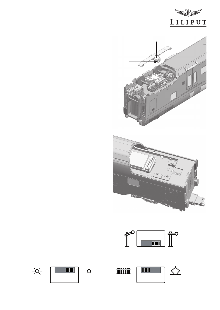
If you wish to run the car in block track
operation or have it automatically stop in a
terminus, please switch the switch S3 to OFF
(Fig. 3a). This will ensure that power pick up
only takes place at the end carriage that is
currently fronting the train.
Switch S2 enables you to switch the power
pick up from wheel contact to overhead
contact operation.
Switch S1 enables you to switch the interior
lighting on and off. For digital operation the
switch is set to AUX1; interior lighting is
activated from the decoder.
ON
TRACK
Fig. 3a
S3
S2
S1
OFF
PAN
AUX1DC
Installing a Decoder
The digital interface (DS) with 21 + 2 plug contacts (Fig. 4) is located on the same circuit
board as the three function switches. The installed interface board (SP) with its total of 23
plug contacts carries the switching for the stop function. If you wish to convert to digital
operation by installing a decoder (DEC), the stop function is deactivated.
SP
1.
Fig. 4
4 H0 1:87
2.
DEC
DS

Bachmann Europe Plc
) shown. It is advisable to carry
L
Installing a Loudspeaker
The railcar already comes completely
prepared for locomotive sound operation.
The 21-pin sound decoder (SD) can be
SD
SPK
plugged in vertically on the interface.
The holder of the loudspeaker (M) and
the two solder pins (SPK) for the wires
are located in unit 100 near the gangway (Fig. 5).
S3
S2
S1
To install, please remove the body. To
do this fi rst remove the two screws (S)
on the underside, then pull the front
part forwards (Fig. 5a). By splaying (A)
the two outer walls of the body you can
then loosen the body from the bogies.
Refi tting is effected by following the
sequence in reverse.
Fig. 5
M
Looking after your Model
In order to ensure that your model has a long service life, the railcar should undergo maintenance at regular intervals. The model need not be opened to do this. It is perfectly suffi cient
to turn the model over on a soft base as shown in Fig. 5a, but please be careful not to
damage the roof parts or the pantograph in the process. Clean the wheel contacts using
cotton wool buds soaked in spirits and then clean the wheels. However, please do not turn
the drive wheels by hand in any circumstances.
After cleaning please use a drop of machine oil to lubricate
the bearing points (L) shown. It is advisable to carry
out maintenance work after approximately
30-40 hours of operation.
L
L
L
A
L
L
L
S
S
L
L
A
H0 1:87 5
Fig. 5a

Bachmann Europe Plc
The railcar also need not be opened to lubricate the gear parts. It is perfectly suffi cient to
swivel the motor bogie to one side as shown in Fig. 6. Then you can look between bogie
and running gear and see the worm and worm wheel (O) and use a pipette to oil all the gear
parts (Z). Then run the railcar up and down a little. This ensures that the oil is distributed
evenly. Use commercially available oils and use a fi ne cannula or a needle.
Caution: Do not use cooking oil or hand cream!
Z
Z
Fig. 6
Z
O
Your Model as an AC Variant
If you have decided on running your
LILIPUT model using a three rail AC
system, please observe the following:
This model has a digital decoder installed
(ESU Lokpilot) located in unit 100, which
can be used to power your vehicle either
on an analogue basis (16 volt AC) or digitally. Please consult the operating manual
supplied by ESU for details on how the
decoder works.
A slider is installed on the turning bogie
of the end carriages 100 and 600 (Fig. 7)
for power pick up from the centre rail.
This picture shows the installed slider.
6 H0 1:87
R
Fig. 7
Bachmann Europe Plc
Fig. 8 shows the removed slider with the
retaining bracket (R). The retaining bracket
snaps simply into two clip-in lugs. When
taking apart, please press the retention
arm (S) slightly outwards using a small
screwdriver.
Naturally, the wheel profi le of the wheel
sets has also been adapted to the track
system commonly in use.
The alternating current version has a
circuit board with three switches in the
roof section of unit 100. Fig. 9 shows the
position of the individual switches.
Please slide switch S3 into the position
OFF (Fig. 10) for the stop function.
For overhead operation using the pantographs please slide the switch S2 to
the PAN position. S1 must be in position
AUX1 for digital operation. The interior
lighting is turned on and off here with the
decoder.
For all other operating information please
consult pages 3 - 6 under
- Altering the default settings and
opening unit 100
- Installing a decoder
- Installing a loudspeaker as well as
- Looking after your model.
R
S
Fig. 8
Fig. 9
S3
S1
S2
S3
Fig. 10
S1
H0 1:87 7
AUX1DC
ON
AC
S2
OFF
PAN

Bachmann Europe Plc
Circuit Diagrams
For all those desiring more information, we have enclosed the complete circuit diagram for the
car units and the power systems.
Circuit Diagram DC: Unit 100
LED13
R13
2K
Y
LED12
R12
Loco B (R Pickup)
Loco B (M+)
Loco B (M-)
Loco B (L Pickup)
Loco B (Pantograph)
Rear Light+
Front Light+
Interior Light+
GND
TOP/name Light+
123
4
5
9
8
6
10
CONNE
Unit A_R
Unit A_R
Unit A_R
Unit A_R
Unit A_R
B
DCC Aux1
Pantograph
A
Track
DC ON
STOP OFF STOP ON
A B
DC STOP
Power Pickup
Function
Interior LEDs
S3
S1
S2
SW
A
S3S2S1
PANTO DC STOP
SW B
A
DC STOP
S3S2S1
SW B
A
PANTO
S3S2S1
SW B
7
Unit A_L
R
LED4
R4
M-
M+
GND
Unit B_L
Unit B_R
Front Light+
Rear Light +
Interior Light+
TOP/name Light+
Unit A_L
Unit B_PAN
Unit A_L
Unit A_L
Unit 100 (A)
DC
Unit A_L
Unit B_R
Unit B_PAN
Unit A_R
Unit A_PAN
PAN TO
S2A
S2
S3A
S3
Unit B_L
Unit A_L
TRACK
PAN TO
TRACK
AAB
B
S2B
ON
OFFONOFF
AAB
B
S3B
2K
LED3
R3
2K
Rear Light +
Q2
8550
VCC
TOP/Front Light+
Q1
8550
VCC
R
C2
105
R06
4.7K
10K
R02
D2
C6 105
LED_R
W
LED5
R5
2K
LED2
W
R2
2K
LED1
R1
2K
W
C1
105
R05
4.7K
C5 105
R01
10K
D1
LED_F
2K
Y
LED11
R11
2K
Y
104
104
LED10
R10
2K
Y
LED9
R9
2K
Y
LED8
R8
2K
C4
105
Interior Light+
Q4
Rear Light X 2PCS(LEDXX+10175)
8550
R04
10K
VCC
PTC1
V+
MISCE#500MA
R7
2K
R6
2K
name Light+
C3
Front Light X 2PCS(LEDXX+10145)
105
TOP LED X 1PCS(LEDXX+10145)
Q3
8550
10K
R03
VCC
AUX_1
V+
LED_F
V+
LED_R
V+
4
2
A
1
3
R1
NC
NC
NC
AUX 4
L1
M+
L
R
GND
D?
B
21
22
20
18
19
M+
M+
L1 4.7uH
Interior Light X 6PCS (LEDXX+10205)
Y
R08
4.7K
C8 105
LED7
Y
LED6
Y
C7 105
S1
B
A
DC
AUX1
Station name Light X 2PCS (LEDXX+10205)
R07
4.7K
D3
D4
D5
LED_F
AUX_1
LED_R
LED_FR
R20 220K
R18 220K
R19 220K
LED_F
LED_R
8
7
11
10
6
9
NC5NC
NC
LEDF
LEDR
SPEAK2
SPEAK1
NC
M-
17
M-
M-
L2 4.7uH
V+
SPK
AUX1
AUX 3
AUX2
VDD
V+
CONN2
13
14
12
16
15
AUX_2
C04
104
+
22UF/35V
C0
1
DC
A
S3S2S1
SW B
1
2
2
MOTOR
C05
104
C04
104
8 H0 1:87

Bachmann Europe Plc
Circuit Diagram DC: Unit 100 / jumper plug
D3392 DOSTO DC TRACK
D1...D16(DIODE#10187)
D1
D8
D6
V+
D3
D2
M+
M-
D4
C0N1
B
22
21
20
19
18
17
16
15
14
13
12
A
L1
R1
1
R
NC
CONN2
2
L
NC
3
GND
NC
4
M+
AUX 4
5
M-
NC
Q2
6
NC
NC
8050
7
V+
LEDR
8
AUX1
LEDF
9
AUX2
SPEAK1
10
AUX 3
SPEAK2
11
VDD
NC
Front R
Front L
D16
R
D7
D5
L
D13
D3392+PCB10 (23Pin Dummy Board)
Circuit Diagram DC: Unit 200, 300, 400, 500 and 600
Unit 200 Unit 300 Unit 400 Unit 500
Front Light+
Interior Light+
GND
TOP/name Light+
Front Light+
Interior Light+
GND
TOP/name Light+
Rear Light+
Loco B (R Pickup)
Loco B (M+)
Loco B (Pantograph)
Loco B (M-)
Loco B (L Pickup)
Interior Light+
CONNE
1
2
3
4
5
10
9
8
7
6
R3
R7
R1
R2
2K
2K
2K
2K
105
Y
Y
Y
Y
LED3
LED2
LED1
LED7
105 105
R4
2K
Y
CONNE
1
2
3
4
5
10
9
8
7
6
R5
2K
Y
LED5
LED4
Front Light+
Interior Light+
GND
TOP/name Light+
Rear Light+
Loco B (R Pickup)
Loco B (M+)
Loco B (Pantograph Pickup)
Loco B (M-)
Loco B (L Pickup)
R8
R6
2K
2K
105
Y
LED6
LED8
Y
Rear Light+
Loco B (R Pickup)
Loco B (M+)
Loco B (Pantograph)
Loco B (M-)
Loco B (L Pickup)
Interior Light x 8pcs
R2
2.2K
R4
2.2K
Q4
8050
Front Light X 2PCS(LEDXX+10145)
TOP LED X 1PCS(LEDXX+10145)
CONNE
Front Light+
W
R1
2.2K
Q1
8050
8050
Unit B_L
1
2
3
4
5
10
9
8
7
6
Unit B_R
R2
R1
2K
2K
LED2
LED1
W
Rear Light +
R3
2K
LED3
R
D15
C1
104
R_1
D12
D11
R3
2.2K
D10
Q3
D9
L_1
D14
C2
104
DC Unit 600 (B)
Unit B_L
B
Unit B_PAN
Unit B_R
name Light+
R5
2K
LED5
R4
2K
LED4
R
R6
R7
2K
2K
LED6
Y
W
Station name Light X 2PCS (LEDXX+10205)
Interior Light+
105
LED7
Y
R8
2K
Y
LED8
Rear R
Rear L
Unit B_L
Unit B_R
C01
104
C02
104
R10
R9
2K
2K
Y
Y
LED9
Unit B_L
Unit B_R
L1
M+
4.7uH
1
1
MOTOR
2
2
L2
M-
4.7uH
R13
R12
R11
2K
2K
2K
105
Y
Y
Y
LED11
LED13
LED12
LED10
Rear Light X 2PCS(LEDXX+10175)
Interior Light X 6PCS (LEDXX+10205)
H0 1:87 9

Circuit Diagram AC: Unit 100
Loco B (AC Pickup)
Rear Light+
Front Light+
Interior Light+
TOP/name Light+
GND
123410
9
5
CONNE
R Wheel
M+
GND
R Wheel
Unit A_R
R Wheel
R Wheel
DCC Aux1
A B
Track Pantograph
DC ON
STOP OFF STOP ON
DC STOP
Power Pickup
Function
Interior LEDs
S3S2S1
SW
ASW B
PAN STOP
S3S2S1
ASW B
AC STOP
S3S2S1
ASW B
PAN
S3S2S1
ASW B
AC
S3S2S1
Unit B_AC
Rear Light +
Front Light+
Interior Light+
TOP/name Light+
AC Unit 100 (A)
A B
Unit A_AC Unit B_AC
Unit A_PAN Unit B_PAN
PAN TO
AC
PAN TO
AC
1
3
4
6
AAB
B
S2A
S2B
S2
2
5
K1A
K1
Bachmann Europe Plc
LED13
R13
2K
Y
LED12
R12
2K
Loco B (Pantograph Pickup)
Loco B (L Pickup)
Loco B (M+)
Loco B (M-)
8
6
7
L Wheel
M-
L Wheel
Unit B_ L
Unit B_PAN
B ACA AC
ON
OFF
4
6
AAB
S3A
S3
5
K1B
Rear Light +
Q2
8550
Unit A_L
L Wheel
VCC
L Wheel
TOP/Front Light+
Q1
8550
VCC
OFF
ON
1
3
B
S3B
2
A
B
RELAY-DPDT
D6
D5
R0
220
V+
R
LED4
R4
2K
LED3
R3
2K
R
C2
105
R06
4.7K
10K
D2
C6 105
R02
W
LED5
R5
2K
LED2
W
R2
2K
LED1
R1
2K
W
C1
105
R05
4.7K
D1
R01
10K
C5 105
Q5
8050
Q6
8050
104
C10
R14
R15
10K
R17
220K
AUX_4
AUX_4
AUX_3
AUX_3
Interior Light+
Rear Light X 2PCS(LEDXX+10175)Front Light X 2PCS(LEDXX+10145)
Q4
VCC
LED_R
PTC1
V+
name Light+
TOP LED X 1PCS(LEDXX+10145)
Q3
LED_F
VCC
AUX_3
104
C9
AUX_3
10K
R16
220K
Y
LED11
R11
2K
Y
104 104
LED10
R10
2K
Y
LED9
R9
2K
Y
LED8
R8
2K
C4
105
8550
R04
10K
MISCE#500MA
R7
2K
R6
2K
C3
105
8550
10K
C7 105
R03
AUX_4
AUX_4
Interior Light X 6PCS (LEDXX+10205)
Y
R08
4.7K
C8 105
S1
B
A
DC
AUX1
LED7
Y
LED6
Y
Station name Light X 2PCS (LEDXX+10205)
R07
4.7K
D4
D5
D3
LED_F
LED_R
AUX_1
LED_FR
AUX_1
V+
LED_F
LED_R
A
R1
L1
D?
B
R20 220K
V+
R18 220K
V+
R19 220K
LED_F
LED_R
8
6
7
2
4
1
3
NC
NC
NC
AUX 4
M+
L
R
GND
21
22
20
19
M+
M+
L1 4.7uH
11
10
9
NC5NC
NC
LEDF
LEDR
SPEAK2
SPEAK1
NC
M-
18
16
17
M-
M-
L2 4.7uH
V+
1
1
C01
104
SPK
AUX1
AUX 3
AUX2
VDD
V+
CONN2
14
12
15
13
AUX_2
C11
104
+
22UF/35V
C0
2
2
MOTOR
C02
104
10 H0 1:87

Bachmann Europe Plc
Circuit Diagram AC: Unit 200, 300, 400, 500 and 600
M+
L1
4.7uH
1
1
MOTOR
Unit B_L
Unit B_L
B
Unit B_AC
Unit B_PAN
Unit B_L
Unit B_L
B AC
AC Unit 600 (B)
Unit B_L
Unit B_R
2
1
41098756
3
CONNE
GND
Front Light+
Interior Light+
TOP/name Light+
Rear Light+
Loco B (AC Pickup)
Unit B_L
Unit B_L
Loco B (Pantograph)
Loco B (L Pickup)
Loco B (M+)
Loco B (M-)
C01
104
R7
2K
R6
2K
R5
2K
R2
2K
R1
2K
Front Light+ name Light+
M-
L2
4.7uH
2
2
LED13
R13
C02
104
Y
LED7
LED6
Y
Station name Light X 2PCS (LEDXX+10205)
W
LED5
W
LED2
LED1
W
Front Light X 2PCS(LEDXX+10145)
2K
Y
LED12
R12
2K
Y
LED11
R11
2K
Y
105
LED10
R10
2K
Y
LED9
R9
2K
Y
LED8
R8
2K
Y
105
Interior Light+
LED4
R4
2K
LED3
R3
2K
Rear Light +
TOP LED X 1PCS(LEDXX+10145)
Interior Light X 6PCS (LEDXX+10205)
R
R
Rear Light X 2PCS(LEDXX+10175)
105
LED8
R8
2K
Y
LED6
R6
2K
Y
LED5
R5
2K
Y
LED4
R4
2K
Y
105 105
LED3
Y
R3
2K
LED2
Y
R2
2K
LED1
Y
R1
2K
LED7
R7
2K
Y
105
Interior Light x 8pcs
Unit 200 Unit 300 Unit 400 Unit 500
Front Light+
Interior Light+
123410
CONNE
2
1
CONNE
Front Light+
Interior Light+
Loco B (Pantograph Pickup)
Loco B (M+)
Loco B (M-)
Loco B (L Pickup)
Loco B (AC Pickup)
Rear Light+
TOP/name Light+
GND
9
5
6
7
8
4
3
9
875
6
10
TOP/name Light+
GND
Rear Light+
Loco B (Pantograph Pickup)
Loco B (AC Pickup)
Loco B (M+)
Loco B (M-)
Loco B (L Pickup)
Interior Light+
H0 1:87 11

Bachmann Europe Plc
Warranty Coupon
Should your LILIPUT model be faulty or not work properly or require repair, you can either
contact the dealer from whom you purchased the product or contact the customer services
department directly of one of the following addresses below.
GREAT BRITAIN:
BACHMANN EUROPE PLC
MOAT WAY, BARWELL
GB - LEICESTERSHIRE LE9 8EY
GERMANY:
BACHMANN EUROPE PLC
NIEDERLASSUNG DEUTSCHLAND
AM UMSPANNWERK 5
D - 90518 ALTDORF BEI NÜRNBERG
Warranty Conditions:
This LILIPUT model has a warranty of two years from the
date of purchase on repairs and parts, as long as it was
purchased from an authorised dealer and if this certificate
has been stamped with the address of the dealership and
the date of purchase has been entered. The warranty permits Bachmann Europe Plc either to rectify any fault or to
replace the faulty parts. Further claims are excluded.
Please note that no liability can be assumed for any parts
subsequently fitted or for any damage caused thereby.
Important! We recommend that you keep the original box. It is
the best place to store your model, when it is not in use. Please
be aware, that carpet fibres can destroy the fine mechanism of
the locomotive. Subject to changes in design, version and technical data. Please retain these data and instructions for further
reference. This product has been manufactured according to the
European toy Safety Directive (CE). • Wichtig! Wir empfehlen die
Originalverpackung aufzubewahren, sie ist der beste Schutz für
Ihr Modell, wenn dieses nicht gerade auf Ihrer Anlage unterwegs
ist. Beim Betrieb der Lok auf Teppichböden kann die feine Mechanik durch Fasern zerstört werden. Änderungen in Konstruktion
und Ausführung vorbehalten. Bitte bewahren Sie diese Beschreibung zum späteren Gebrauch auf. Dieses Produkt wurde nach
Vorschriften der europäischen Spielzeugrichtlinien
(CE) hergestellt. • Importante! Raccomandiamo di
tenere la scatola originale. E’ il posto migliore in cui
tenere il tuo modello quando non è in uso. Fibre di
tappeti possono distruggere il fine meccanismo del-
SWITZERLAND:
MODELLBAU UND
ELEKTRONIK
STETTBACHSTRASSE 193
CH - 8051 ZÜRICH
ALL OTHER COUNTRIES:
( EXEPT GERMAN SPEAKING COUNTRIES )
BACHMANN EUROPE PLC
MOAT WAY, BARWELL
GB - LEICESTERSHIRE LE9 8EY
Dealer’s stamp with day of purchasing:
la locomotiva. Preghiamo di conservare questi dati ed istruzioni
per altre informazioni. Quest’articolo è stato prodotto in accordo
con la Direttiva Europea Sicurezza giochi (CE).
Attention! At an incorrect use there exists danger of hurting because
of cutting edges and tips • Achtung! Bei unsachmäßigem Gebrauch
besteht Verletzungsgefahr durch funktionsbedingte scharfe Kanten
und Spitzen • Attention! Il y a danger de blessure à un emploi in-
correct à cause des aiguilles et arêtes vives! • Voorzichtig! Bij ondo-
elmatig gebruik bestaat verwondigsgevaar door scherpe zijkanten
en uitsteeksels! • Attenzione! Un uso improprio comporta pericolo
di ferimenti attraverso punte e spigoli taglienti! • Atencion! Un em-
pleo incorrecto puede causar heridas debido a las puntas y aristas
agudas! • Atençao! Por utilizaçao incorrecta existe o perigo de es-
tragos, em virtude de cortes nas abas e nas pontas!
• Προξοχη! Η ακαταλληλη χρηοη εγκλειει κινδυνουζ
μκροτ ραυματιομων, εξ αιπαξ κοπτερων ακμων και
προεξοχωθν • Bemaerk! Ved ukorrekt brug kan de funk-
tionsbetingede skarpe kanter og spidser forfolde skade!
Bachmann Europe Plc · Moat Way · Barwell · Leicestershire · LE9 8EY · England Made in China
12 H0 1:87
 Loading...