

Page 1
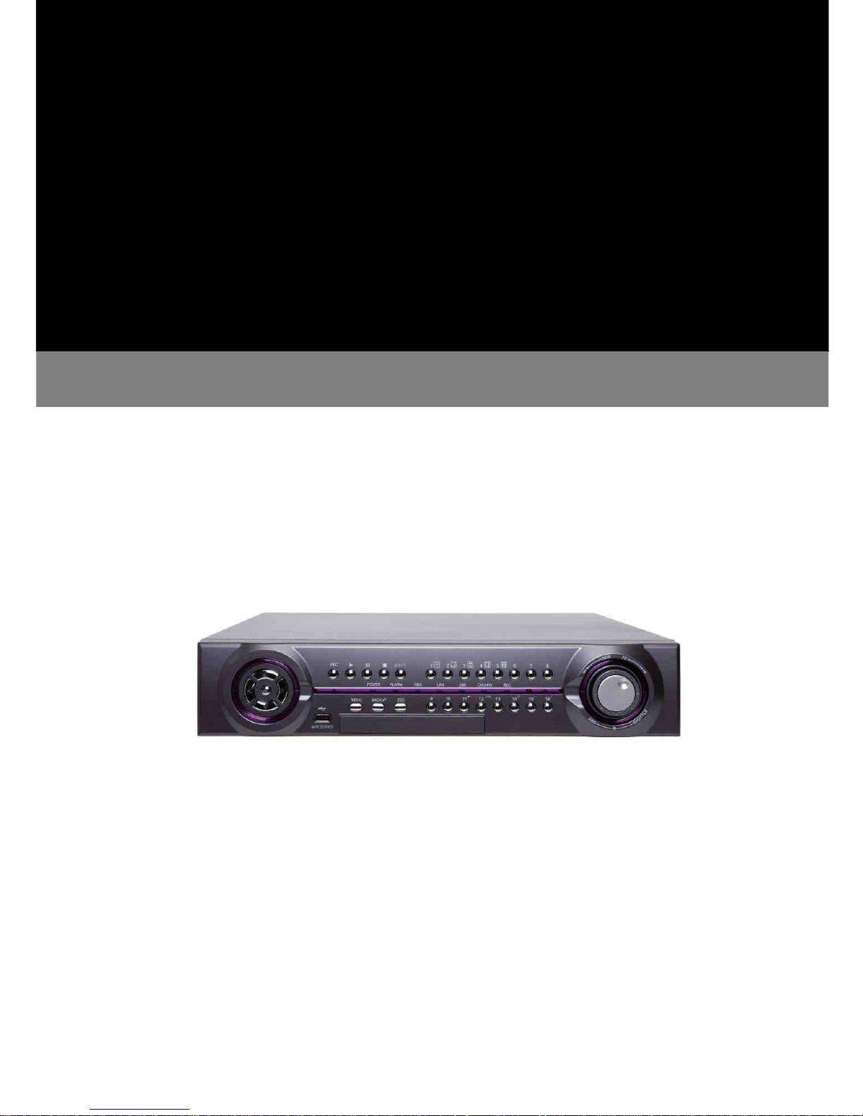
INSTRUCTION MANUAL
DIGITAL VIDEO RECORDER
Page 2

DVR User Manuel 1
Introduction
The DVR series:
• 16CH – 16-channel 2U Standalone Digital Video Recorder
• 16CH – 16-channel 1U Standalone Digital Video Recorder
• 8CH – 8-channel 1U Standalone Digital Video Recorder
DVR series are designed to meet the demands for 8/16-channel 960H and D1 camera real-time
recording systems. Frame rate, video quality, and resolution can be adjusted for each channel to
meet recording requirement. HDMI and VGA engines are built-in 3D intellectual motion adoptive
refinement with vivid image enhancement algorithm to provide best video quality.
DVR series provide various backup features include Slim DVD/RW, USB DVD/RW, USB flash
disk, HTTP download, and Backup Manager FTP for multiple DVRs’ files download. Mobile
phone device remote monitoring is also supported. Browser based remote live monitoring and
video playback features are provided.
DVR series can provides 960H and D1 camera real-time for 8-/16-channel recording and
playback. Full features web-based user interface, multiple DVR system monitoring features, and
various backup features, DVR series is an ideal solution for advanced DVR applications.
Major Features
Touch screen interface.
Support 960H and D1 camera for real-time H.264 recording and playback.
Design for 2U and 1U rack-mount chassis.
Easy-to use jog-and-shuttle button operation (2U).
Full HD 1920*1080P HDMI and VGA output, built-in 3D intellectual motion adoptive
refinement and vivid image enhancement engines.
Support up to 4 SATA HDDs for 16-channel (2U), 2 SATA HDDs for 8/16-channel (1U).
Concurrent multiple-channel playback for 8/16-channel.
Audio recording and playback.
Full features for remote controller.
One cable PTZ coaxial control supported.
HTTP web-based interface including DVR configuration, PTZ control, playback, and live
monitoring.
Support for iPhone, iPad, and Android devices.
Slim DVD R/W support (Optional).
CMX 3.6 software supported.
Page 3
DVR User Manuel 2
Trademarks and registered trademarks
• Microsoft, Windows 2000, Windows XP, Internet Explorer are registered trademarks of
Microsoft Corporation in the U.S and/or other countries.
• Adobe and Adobe PDF are registered trademarks of Adobe Systems Incorporated in the
U.S and/or other countries.
• JavaScript and all Java-based trademarks and logos are trademarks or registered
trademarks of Sun Microsystems, Inc. in the U.S and/or other countries.
• Linux, Macintosh, Mozilla, and Netscape Navigator are registered trademarks of the
respective holders.
• Pelco is a trademark of Pelco - Clovis, CA, and may be registered in certain jurisdictions.
• Other names of companies and their products mentioned in this manual may be
trademarks or registered trademarks of their respective owners.
Caution
• Do not drop or strike the equipment
• Do not install the equipment near naked flames or heat sources
• Do not expose this unit to rain, moisture, smoke or dusty environments
• Do not cover the opening of the cabinet with cloth or plastic or install this unit in a
ventilated place. Allow 10cm between this unit and its surroundings
• Do not continue to operate the unit under abnormal conditions such as detection of
smoke, strange smell or no display on screen whilst power is turned on
• Do not touch the power connection with wet hands
• Do not damage the power cord or leave it under pressure
• To avoid unnecessary magnetic interference, do not operate this unit near magnets,
speaker system, etc.
• All connection cables must be grounded properly
CAUTION
RISK OF EXPLOSION IF BATTERY IS REPLACED
BY AN INCORRECT TYPE.
DISPOSE OF USED BATTERIES ACCORDING
TO THE INSTRUCTIONS
Page 4

DVR User Manuel 3
Contents page
1. Basic Operation ........................................................................................................................... 5
1.1 16CH Front Panel.............................................................................................................5
1.2 8CH Front Panel...............................................................................................................7
1.3 Remote control..................................................................................................................9
1.4 Keyboard.........................................................................................................................10
1.5 Touch Screen..................................................................................................................11
1.6 Mouse operations ........................................................................................................... 12
1.7 Menu symbols................................................................................................................. 12
2. Camera selection......................................................................................................................14
3. Digital zoom.............................................................................................................................. 15
4. Freeze....................................................................................................................................... 17
5. PTZ........................................................................................................................................... 18
6. Audio......................................................................................................................................... 19
7. Playback ................................................................................................................................... 20
7.1 Perform Playback ........................................................................................................... 20
7.2 Select time and date for playback .................................................................................. 20
7.3 Playback controls............................................................................................................ 22
8. Alarm management ................................................................................................................... 24
9. Backup / Export ......................................................................................................................... 26
10. Event........................................................................................................................................ 29
11. Basic web-based browser viewing .......................................................................................... 31
11.1 Web based browser playback....................................................................................... 31
11.2 Web based browser backup......................................................................................... 32
11.3 Web based browser export........................................................................................... 32
12. Backup Manager...................................................................................................................... 33
12.1 Playback exported files................................................................................................. 33
12.2 FTP download............................................................................................................... 39
12.3 Convert already downloaded files ................................................................................ 35
Quick Installation Guide.................................................................................................................36
1. Rear Panel................................................................................................................................ 36
1.1 16CH Rear Panel............................................................................................................ 36
1.2 8CH Rear Panel.............................................................................................................. 38
2. Hard Drive(s)............................................................................................................................. 39
2.1 Adding hard drives........................................................................................................... 39
2.2 Formatting hard drives..................................................................................................... 39
3. Time and Date Settings ............................................................................................................ 40
4. Network Settings....................................................................................................................... 41
Page 5

DVR User Manuel 4
Menu Configuration ....................................................................................................................... 42
1. Setup Menu........................................................................................................................38
1.1 Camera setup .................................................................................................................. 38
1.2 Monitor setup..................................................................................................................44
1.3 Record setup...................................................................................................................42
1.4 Alarm setup...................................................................................................................... 47
1.5 Network setup.................................................................................................................. 50
1.6 System setup...................................................................................................................50
1.7 PTZ setup ........................................................................................................................ 57
2. Web-based Viewing/Setup ........................................................................................................ 60
2.1 Before using Internet browser.......................................................................................... 60
2.2 Logon............................................................................................................................... 60
2.3 Configuring theDVR via web page .................................................................................. 58
Appendix A..................................................................................................................................... 67
1. Connections between a DVR and a RS-485 Keyboard..................................................... 67
2. Connections multiple of between DVRs and a RS-485 Keyboard .................................... 67
3. Connections between a DVR and multiple RS-485 PTZs................................................. 68
4. Alarm I/Os and RS-485 for PTZ......................................................................................... 69
Appendix B RS-485 Input and Output Pin Assignment................................................................ 69
Appendix C Hard Drive Support List.............................................................................................70
Appendix D Support USB-DVD/RW and DVD Disk......................................................................71
Appendix E Supported USB Flash Disk ...................................................................................... 71
Appendix F Hard Disk Recording Table.......................................................................................71
Appendix G Touch Screen Monitor Support List.......................................................................... 72
Appendix H Troubleshooting & FAQ ............................................................................................ 72
Specification sheet......................................................................................................................... 73
Page 6
DVR User Manuel 5
User Guide
Chapter 1: Basic Operation
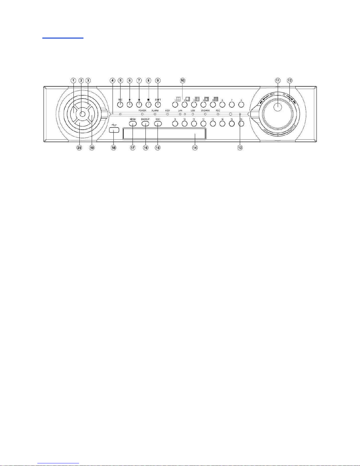
1.1 [16CH 2U Front Panel]
1. Left
Move cursor left
Pan left
Decrease value
2. Enter
Enter operation in menu setup
Instant PTZ camera selection at live
mode
Camera active
3. Up
Move cursor up
Tilt up
4. LED status panel
5. REC button
Start or stop recording
6. Play button
Use this button to start playback
7. Pause button
8. Stop button
9. Shift
Mode switch for split-display or
camera selection
10. Split-display/camera buttons
4, 8, 9, 13, 16 split-display
Camera selection mode
11. Jog dial
Play recorded image frame by frame in
playback
Perform zoom in and out
12. Shuttle ring
Fast forward video in playback mode.
13. IR receiver
14. Built-in Slim DVD/RW drive
(DVD model only)
15. ESC button
16. Backup button
17. Menu button
18. USB 2.0 connector
USB flash disk
USB DVD/RW
19. Right button
Move cursor right
Pan right
Increase value
20. Down button
Move cursor down
Tilt down
Page 7
DVR User Manuel 6
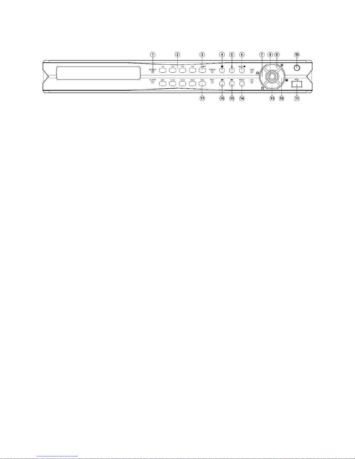
[16CH 1U Front Panel]
1. LED status panel
2. Camera buttons
Camera selection mode
3. Shift
Mode switch for split-display or
camera selection
4. Pause button
Live: freeze video,
playback: pause video
5. Play button
Use this button to start playback
6. Stop button/ ESC button
7. Left
Move cursor left
Pan left
Decrease value
13 split-display
8. Enter
Enter operation in menu setup
Instant PTZ camera selection at live
mode
Camera active
9. Up
Move cursor up
Tilt up
9 split-display
10. IR receiver
11. USB 2.0 connector
USB flash disk
USB DVD/RW
USB Mouse
12. Right button
Move cursor right
Pan right
Increase value
16 split-display
13. Down button
Move cursor down
Tilt down
4 split-display
14. Menu button
15. Fast forward button
Video fast forward
Next event page
16. Fast reverse button
Video fast reverse
Previous event page
17. REC button
Start or stop recording
Page 8
DVR User Manuel 7
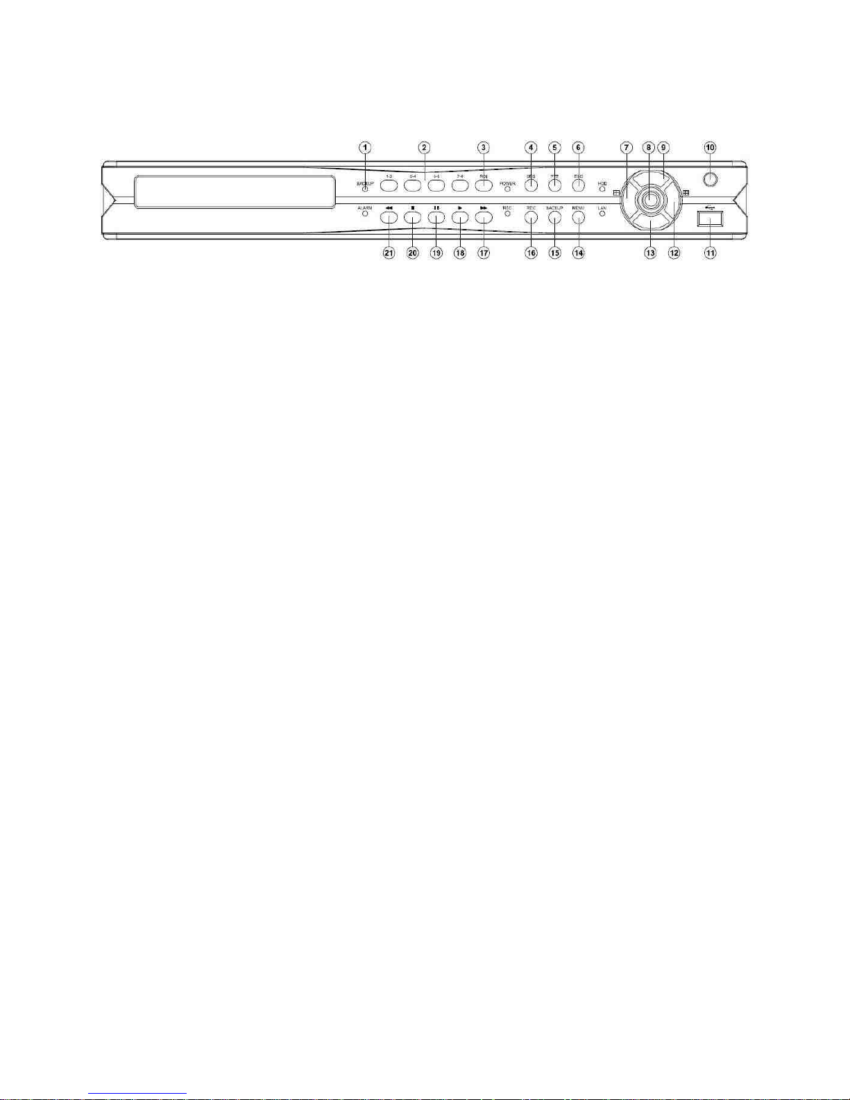
1.2 [8CH Front Panel]
1. LED status panel
2. Camera buttons
Camera selection mode
3. ROI/ ZOOM
Digital Zoom
4. SEQ button
5. PTZ button
At PTZ control mode
At Split-display mode
6. ESC button
7. Left
Move cursor left
Pan left
Decrease value
4 split-display
8. Enter
Enter operation in menu setup
Instant PTZ camera selection at live
mode
Camera active
9. Up
Move cursor up
Tilt up
10. IR receiver
11. USB 2.0 connector
USB flash disk
USB DVD/RW
USB Mouse
12. Right button
Move cursor right
Pan right
Increase value
9 split-display
13. Down button
Move cursor down
Tilt down
14. Menu button
15. Backup button
16. REC button
Start or stop recording
17. Fast forward button
Video fast forward
Next event page
18. Play button
Use this button to start playback
19. Pause button
Live: freeze video
playback: pause video
20. Stop button
21. Fast reverse button
Video fast reverse
Previous event page
Page 9
DVR User Manuel 8
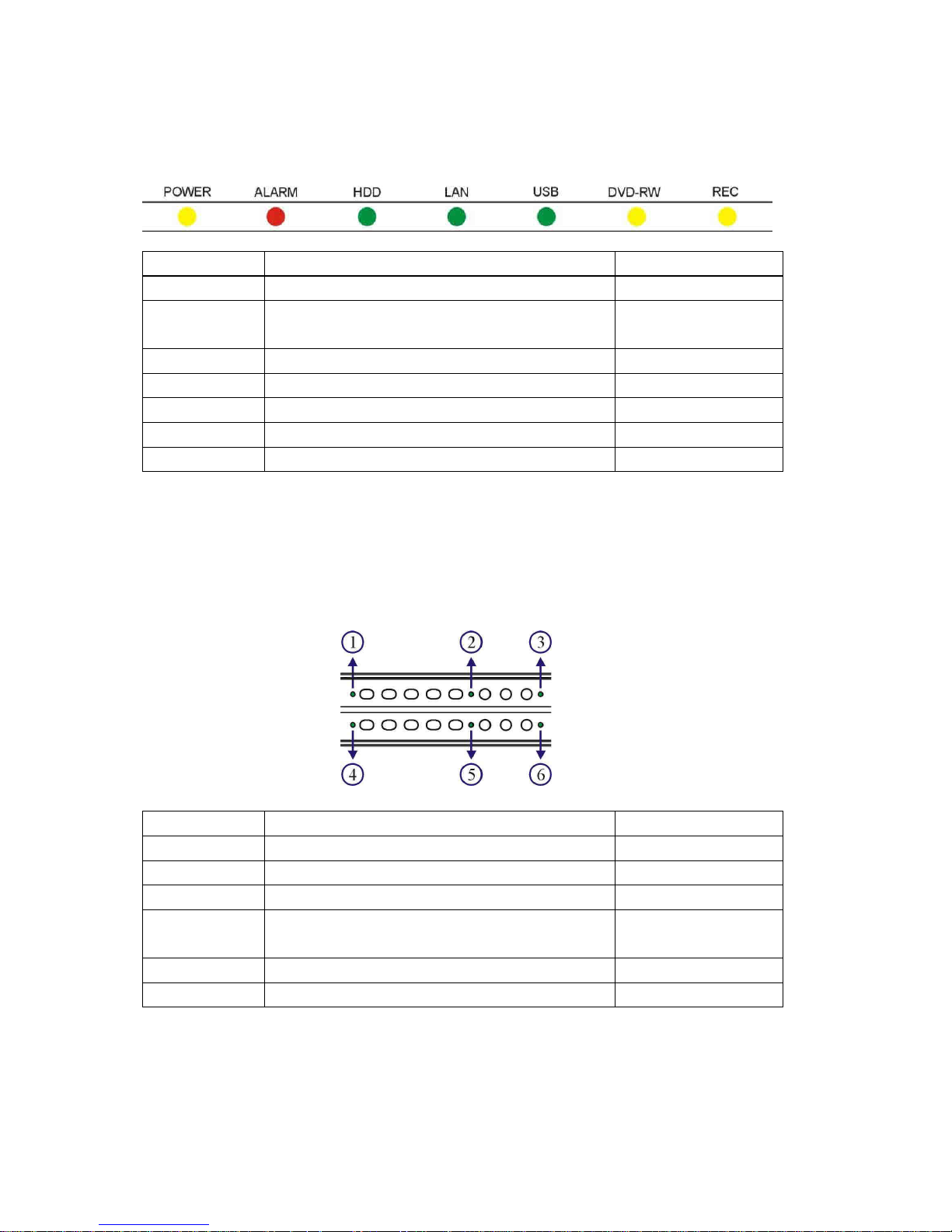
[16CH 2U LED Panel]
The status of each LED is described in the following table:
LED Description Colour
POWER DVR power on/off indicator Yellow
ALARM External alarm switches indicate motion or
alarm triggers
Red (flashing)
HDD HDD recording indicator Green (flashing)
LAN LAN access light Green
USB USB device access light Green
DVD-RW Backup LED indicator Yellow (flashing)
REC Recording indicator Yellow
[16CH/ 8CH 1U LED Panel]
The status of each LED is described as in the following table:
LED Description Colour
BACKUP Backup LED indicator Green (blinking)
POWER DVR power on/off indicator Yellow
HDD HDD recording indicator Green (blinking)
ALARM External alarm switches indicate motion or
alarm triggers
Red
REC Recording indicator Yellow
LAN LAN access light Green
Page 10
DVR User Manuel 9
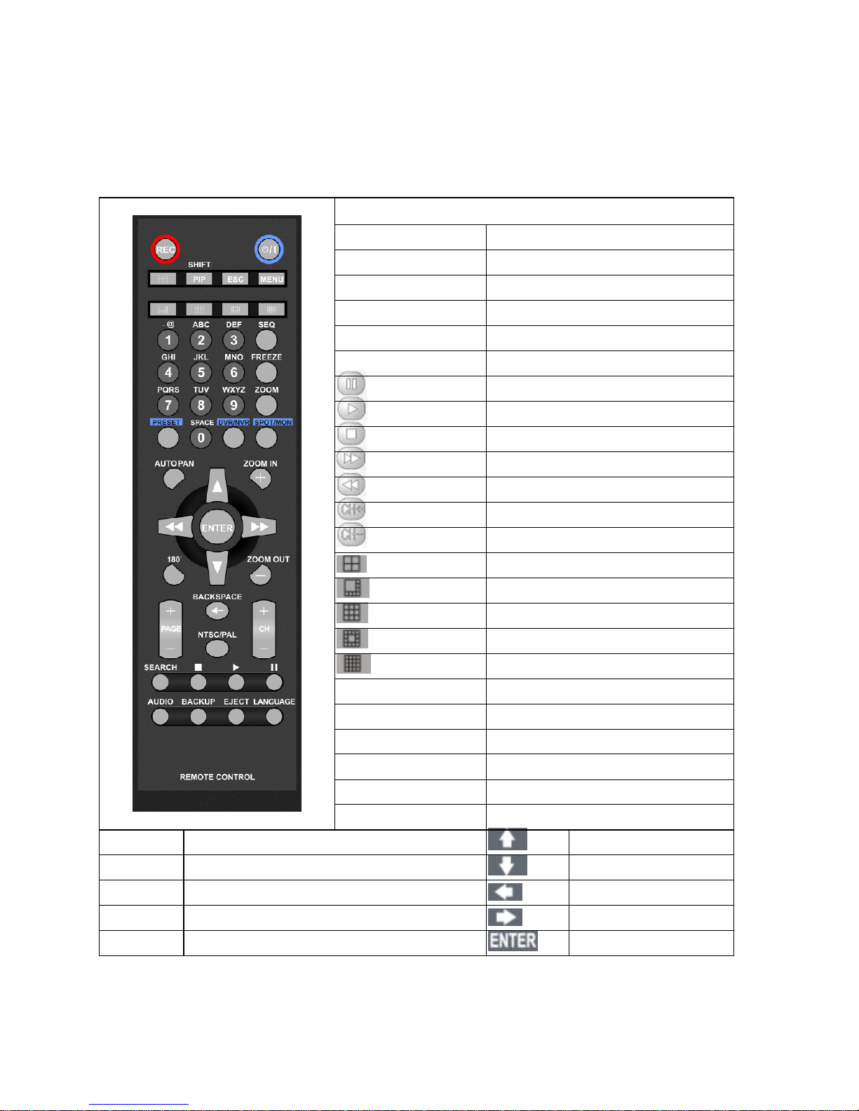
1.3 Remote control
The remote control is a small wireless handheld device with an array of buttons for adjusting
settings. The buttons are separated in regions based on their features including DVR operational
keys, Pan, Tilt, and Zoom (PTZ) and numerical keys.
DVR remote control operational keys
MENU Setup menu
ESC Escape/exit/stop
SHIFT Split and full screen switch
ZOOM Digital video zooming
REC Record/stop recording
FREEZE Live video freeze
Pause
Playback
Stop
Fast forward
Fast rewind
Next single channel
Previous single channel
4 split display
8 split display
9 split display
13 split display
16 split display
AUDIO Audio/mute
BACKUP Video backup
DVR/DVR AddressableDVR control
LANGUAGE Language selection
BACKSPACE Delete character
Auto Pan Perform auto pan feature Move up/tilt up
Zoom in Zoom in Move down/tilt down
Zoom out Zoom out Move left/pan left
Preset Call preset Move right/pan right
0 to 9 Numerical keys Enter/set
Page 11
DVR User Manuel 10
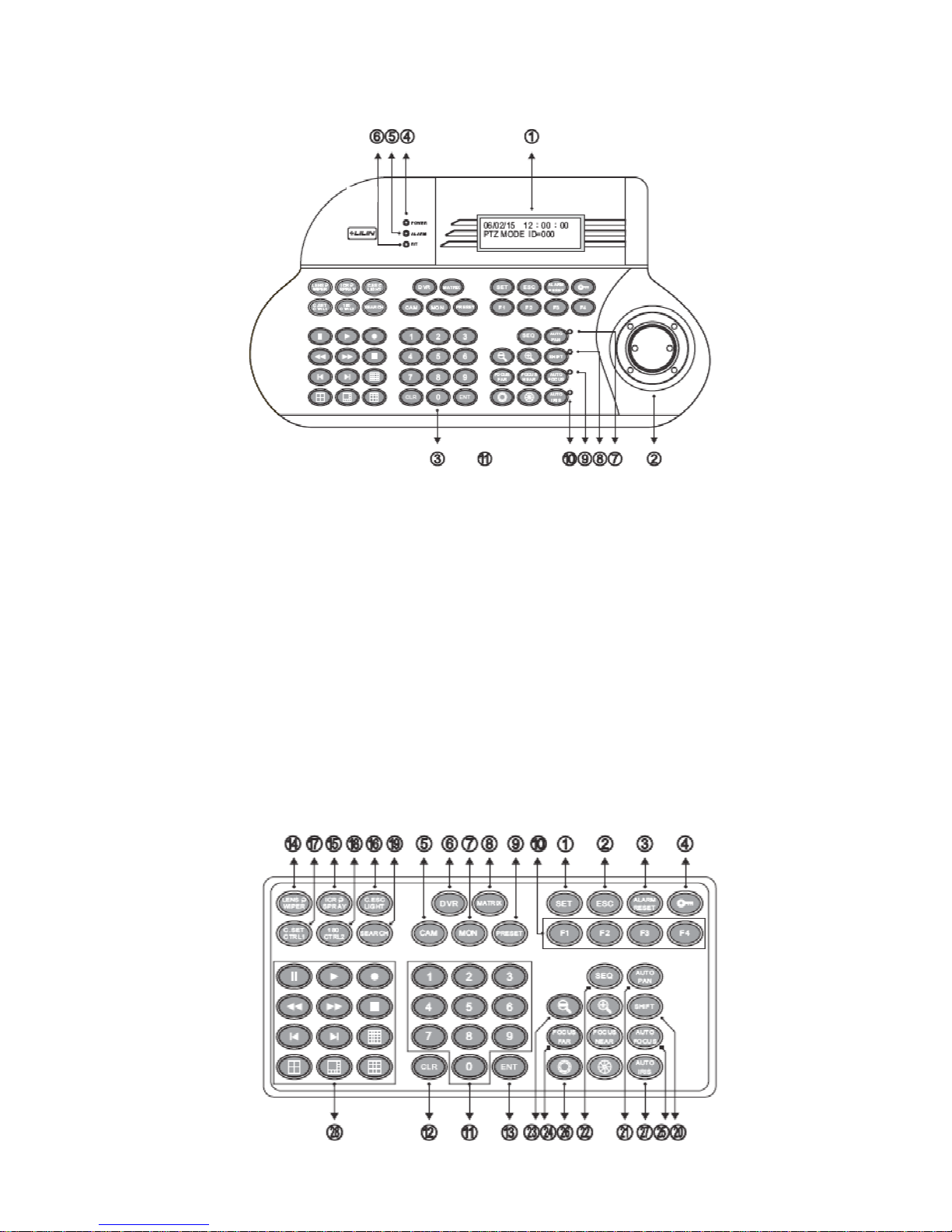
1.4 Keyboard
Keyboard controls
1. LCD display – display the keyboard system setup menu and operation information
2. Joystick – 3 axis (Pan/Tilt/Zoom) / 2 axis (Pan/Tilt)
3. Keypad panel – there are 54 keys which can control PTZ, matrix, DVR and telemetry
receivers
4. Power indicator
5. Alarm indicator
6. R/T indicator – data communication indication
7. Auto pan indicator
8. Shift indicator – shift key status indication
9. Auto focus indicator
10. Auto iris indicator
11. RJ-45 connector
Page 12
DVR User Manuel 11
1. Set – enter setup menu mode
2. ESC – exit
3. Alarm reset – reset alarms and video
loss alarms
4. Keyboard lock – press for 2 seconds
to enter locking mode, press again to
unlock the keyboard
5. Cam – select a particular camera
6. DVR – select a DVR
7. Mon – select a monitor
8. Matrix – press shift + matrix to switch
to matrix control mode
9. Present – recall and store preset
options
10. Function keys
11. Numerical keys – 0-9 for entering
monitor, DVR, camera number
12. CLR – clear to setting data
13. ENT – enter or confirm data
programming
14. Wiper/lens
15. Spray
16. Light/C.ESC
17. CTRL 1 / C.SET
18. CTRL 2 / 180
19. Search
20. Shift
21. Auto pan
22. SEQ
23. Zoom in / zoom out
24. Focus far / focus near
25. Auto focus
26. Iris open / iris close
27. Auto iris
28. DVR control keys
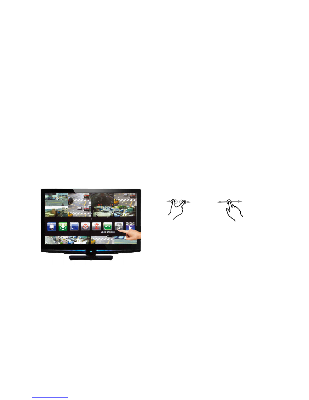
1.5 Touch screen
Scroll screen: Swipe in from the left to right frame onto the screen (vice versa) to browse
through menus
Single tap: Select the icon you would like to access by single-tap the icon
Double tap: Return back to the previous menu by double-tapping the screen under camera view
1.6 Mouse operations
The DVR has a USB mouse interface
Pinch Zoom Out Swipe
Page 13
DVR User Manuel 12
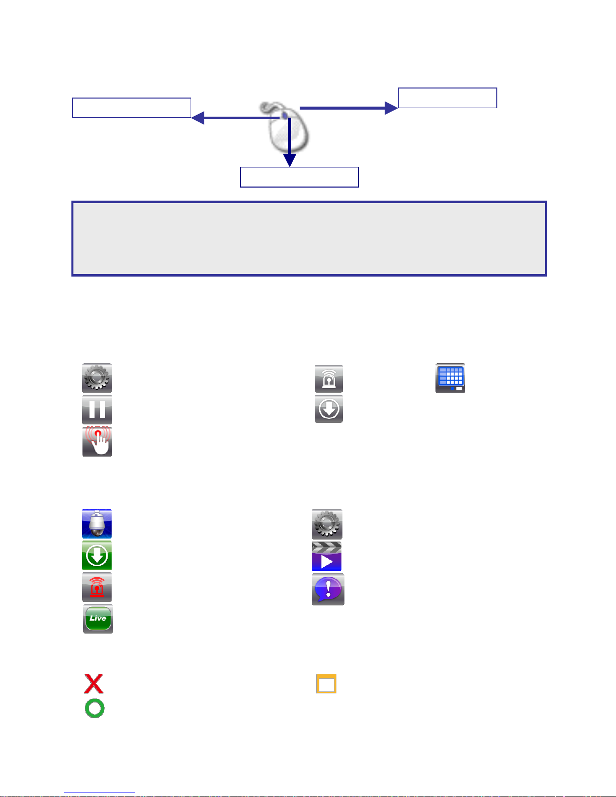
General mouse operations can be used to navigate the device
1.7 Menu symbols
Home short cut keys:
Menu
Pause
Alarm Schedule Rec
Backup
Manual Rec
Main menu keys:
PTZ
Export / backup
Alarm manager
Live display
Configuration menu
Playback
Event
Additional menu keys:
– Return to previous screen
– Return to live mode
– Save and return to previous screen
Right mouse click
Mouse scroll
Left mouse click
Note: The DVR can be controlled via multiple methods: a) front panel (16CH only), b) keyboard, c)
IR remote control, d) touch screen monitor, or e) USB mouse. For this manual, USB mouse and
touch screen will be together referred to as one operation – “touch screen monitor/mouse”
hereinafter. For specific operations, “touch screen” or “mouse” will be referred to separately.
Page 14
DVR User Manuel 13
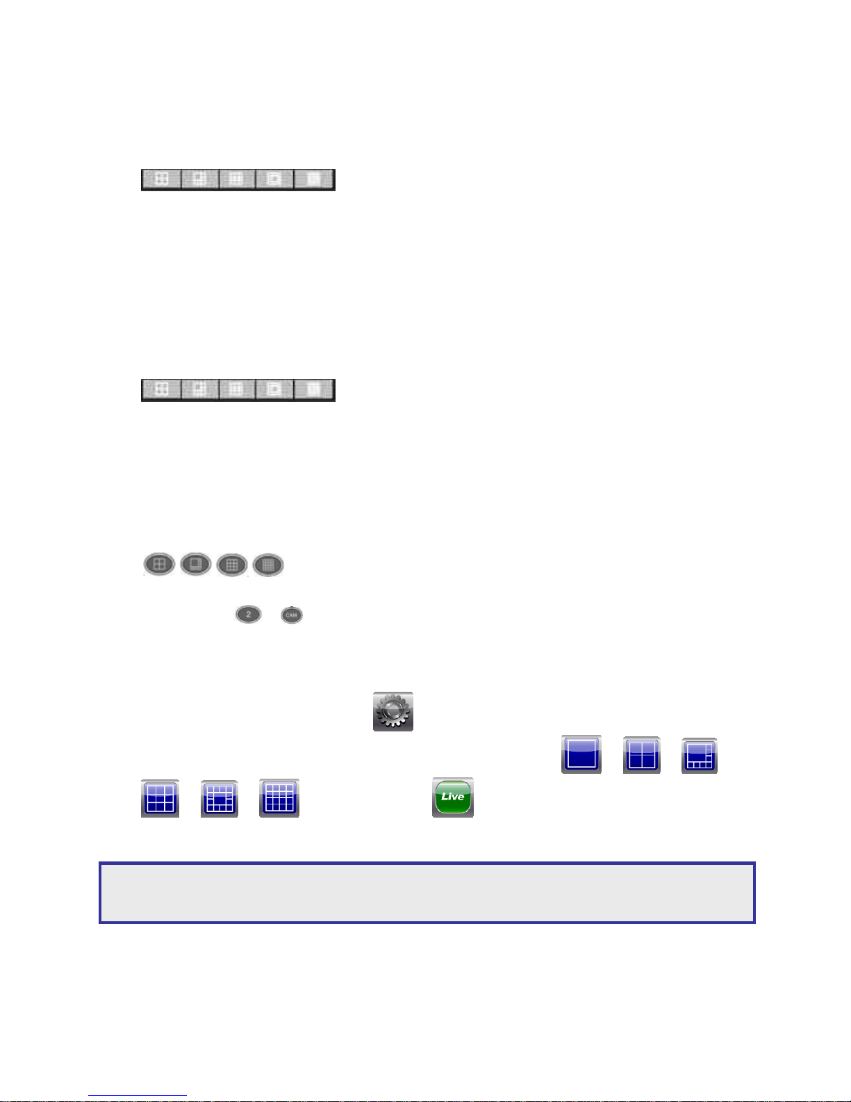
Chapter 2: Camera selection
a. Via front panel
• To select multi-screen view by clicking into one of the following screen-split style icons:
to view.
• To select a single full-screen view, press Shift key on your keyboard and place your mouse
cursor over the camera video you would like to view.
• To revert back to multi-screen view by pressing Shift key on your keyboard once again.
b. Via remote control
• To select multi-screen view by clicking into one of the following screen-split style icons:
• To select a single full-screen view, enter the camera number; e.g. for camera 3, press ‘03’.
c. Via keyboard
• To select multi-screen view by clicking into one of the following screen-split style icons:
• To select a single full-screen view, enter the camera number and click on the CAM button to
proceed; e.g. +
d. Via touch screen monitor / mouse
• To select multi-screen view, press
• Choose the view you desire by selecting one of the followings: or or or
or or , and then click into to proceed.
• To revert back to multi-screen view by clicking on wherever of the image screen.
Note: When the camera title is shown the color yellow, this means you hold control over the
particular camera.
Page 15

DVR User Manuel 14
Chapter 3: Digital zoom
The DVR provides 64x digital zoom capacity for live monitoring and video playback modes. To
digitally zoom in/out the video, please follow the steps below:
a. Via front panel
1. Select desired channel
2. To zoom in or zoom out by using inner control on jog shuttle
3. To move the video screen by using direction keys (move to left, right, up, or down)
4. To return to constant live view press Shift key
5. Click onto the desired camera channel then proceed selecting a different camera screen
view
b. Via remote control
1. Select the desired channel
2. Press Zoom button to perform zoom-in or zoom-out
3. Use directional keys to move the video screen left, right, up, and down
4. To return to constant live time video view by choosing one of the following screen-split style
icon:
c. Via keyboard
Alternative method
d. Via touch screen monitor
1. Select desired channel
2. Use pinch-to-zoom technique to perform zoom-in and zoom-out
3. Swipe in from left to right, right to left, up to down, or down to up onto the screen to
browse through the entire touch screen features.
4. One tap any space on the screen in order to return back to constant live view
5. To return to live view, tap once anywhere on the image
e. Via mouse
1. Select desired channel
2. To zoom in and out by using mouse wheel
3. Left-clicking the mouse, drag and release the mouse in order to move the video screen
4. To return to constant live view by clicking anywhere on the video screen
Page 16

DVR User Manuel 15
Chapter 4: Freeze
The DVR can freeze live video screen images and perform playback. The DVR is still recording
although it is under “freeze” mode.
a. Via front panel
1. Press Pause icon on the front panel
2. The Pause icon at the top left-hand corner of the screen will be highlighted in colour blue
once being paused
3. To return to live mode by pressing Pause icon again
b. Via remote control
1. Press Pause icon on the remote control
2. Once paused, the pause icon at the top left-hand corner of the screen will be highlighted in
colour blue
3. To return to live mode by pressing the Pause icon again
c. Via keyboard
1. Press the Pause button on the keyboard
2. Once paused, the pause icon at the top left-hand corner of the screen will be highlighted in
colour blue
3. To return to live mode by pressing the Pause key again
d. Via touch screen monitor / mouse
1. Press the Pause icon at the top left-hand corner of the screen
2. Once paused, the pause icon will be highlighted in colour blue
3. To return to live mode by pressing Pause icon again
Page 17
DVR User Manuel 16
Chapter 5: PTZ
The camera that has PTZ feature (pan, tilt, and zoom) is able to be managed as the following
methods:
a. Via front panel
1. Select the desired channel
2. Use direction arrow pointer to pan and tilt the image
b. Via remote control
1. Select the desired channel
2. Use direction arrows to pan and tilt the video image
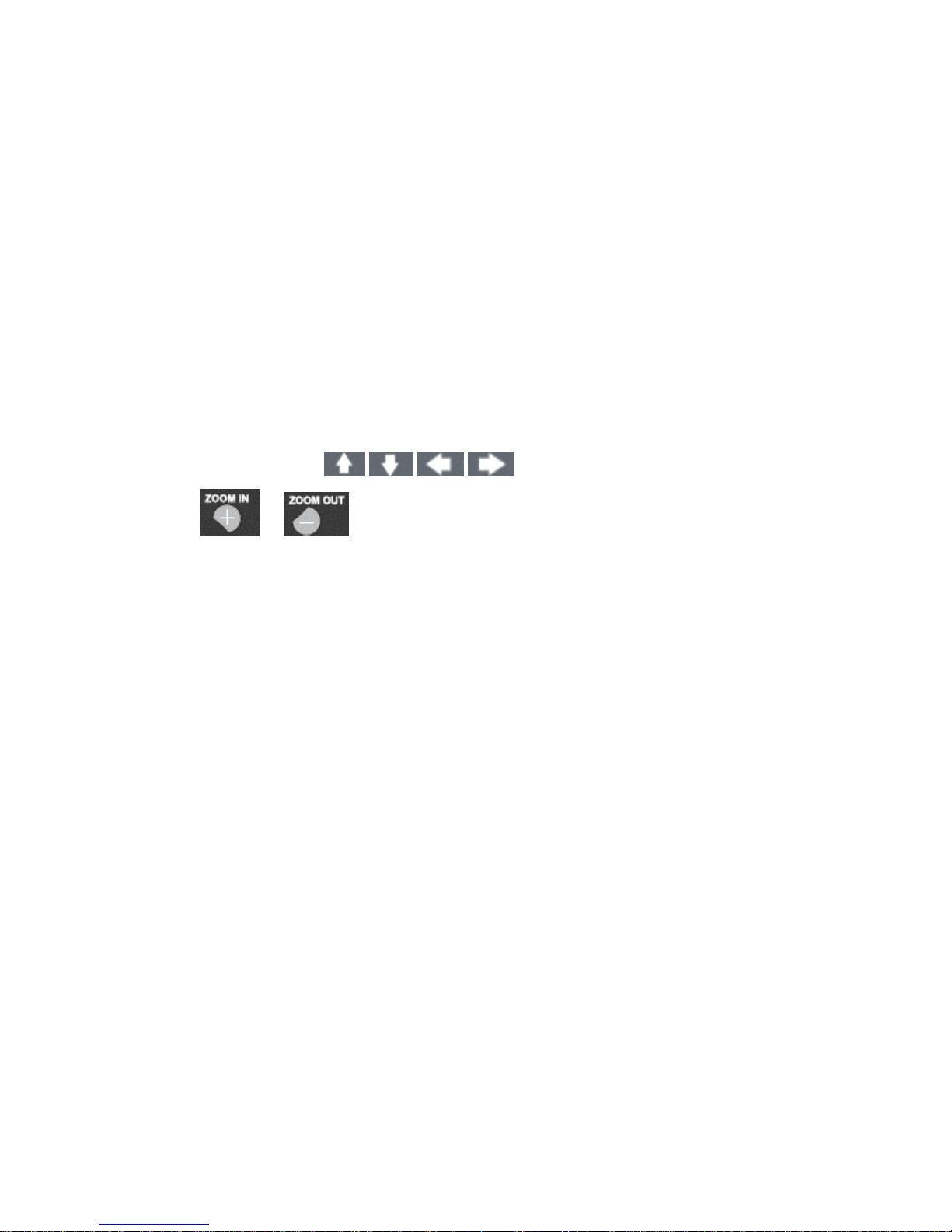
3. Use or keys to zoom-in or zoom-out the video image
4. Press Preset icon and enter the camera number to get the camera back to the preset
position. For example, for preset 3 – press Preset icon followed by entering “003”
5. Press Auto button to start auto pan tour
6. To deactivate the auto pan tour by pressing Auto button again
c. Via keyboard
1. Select the desired channel
2. Use joystick (left, right, up and down) icon to pan and tilt the image
3. Twist and drag the joystick icon to zoom the image
4. Press Preset icon and enter the camera number to get the camera back to the preset
position. For example, for preset 5 – press Preset icon followed by entering “005”
5. Press Auto Pan to start auto pan tour
6. To deactivate the auto pan tour, press Auto Pan again
Page 18
DVR User Manuel 17
d. Via touch screen monitor/ mouse
1. Select required channel
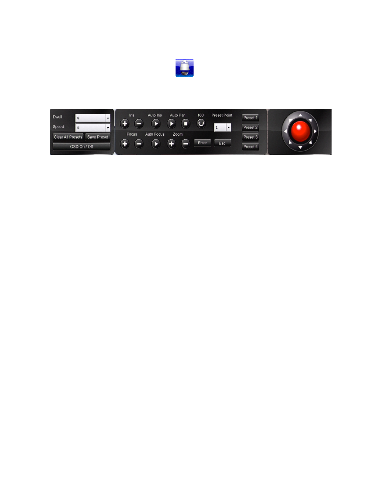
2. Select menu button, press PTZ icon
3. Use the control icons shown below to perform PTZ. The red joystick shown on the right
can be used to navigate through the entire video image.
4. Press ESC to return back to main menu
Chapter 6: Audio
a. Via remote control
• To enable audio by selecting the desired channel
• Press Audio on the remote control to enable live audio
• Press Audio on remote control again to disable live audio
For all other methods, mute volume to disable audio
Page 19
DVR User Manuel 18
Chapter 7: Playback
7.1 Perform Playback
a. Via front panel
To access playback by pressing the Play button
b. Via remote control
To access playback by pressing the Play button
c. Via keyboard
To access playback by pressing the Play button
d. Via touch screen monitor / mouse
To access playback by pressing then click on
7.2 Select time and date for playback
a. Via front panel
• Use up and down keys to navigate time frame (minute, hour, month, year)
• Use left and right keys to position unit selector
• To start playback by pressing Enter key
or
Press Shift key to move between recorded data and time search
• Use to select time and date and press Enter key
Page 20

DVR User Manuel 19
b. Via remote control
• Use to navigate time frame (minute, hour, month, year)
• Use to position unit selector
• To start playback, press ‘enter’
or
Press Shift key to move between recorded data and time search.
• Use to select time and date and press Enter key
c. Via keyboard
• Use joystick directions up and down to navigate time frame (minute, hour, month, year)
• Use joystick left and right to position unit selector
• To start playback twist zoom the joystick
d. Via touch screen monitor
• Select the specific time frame by pressing the time desired and then select the time by
dragging the box
or
Use pinch-to-zoom technique to change time frame
• Select the time by dragging unit selector
or
To perform playback by tapping desired time within camera bar
e. Via mouse
• Navigate time frame by pressing the desired time period
• Select the time you would like to view by dragging unit selector
or
Use mouse to enter time and date in time search bar using the scroll wheel or up and
down arrows on screen
• To perform playback by clicking on the playback icon
Page 21
DVR User Manuel 20
7.3 Playback controls
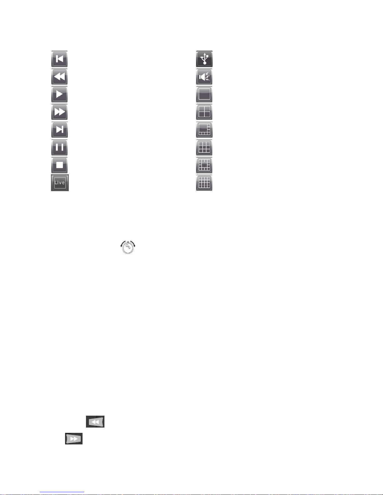
Step rewind
Rewind
Play
Fast forward
Step fast forward
Pause
Stop
Live view
USB
Audio
Full screen view
Quad view
8-screen view
9-screen view
13-screen view
16-screen view
a. Via front panel
Use front keys to play, stop or pause
Use jog shuttle control to perform fast-forward or remind
Use inner circle on jog shuttle to perform rewind or forward
To select individual cameras or change screen view by following camera selection process
To turn audio on or off by pressing Menu button
To activate WYSIWYG (what you see is what you get) backup by inserting USB card and
pressing “backup”
Backup function is commenced if the USB icon light is on
To stop recording by pressing Backup button again
To exit playback by pressing Stop or Escape button
b. Via remote control
Use remote keypad to play, stop or pause
Use button to rewind
Use to fast forward. Press once for 2x and subsequent press to increase speed
Page 22
DVR User Manuel 21
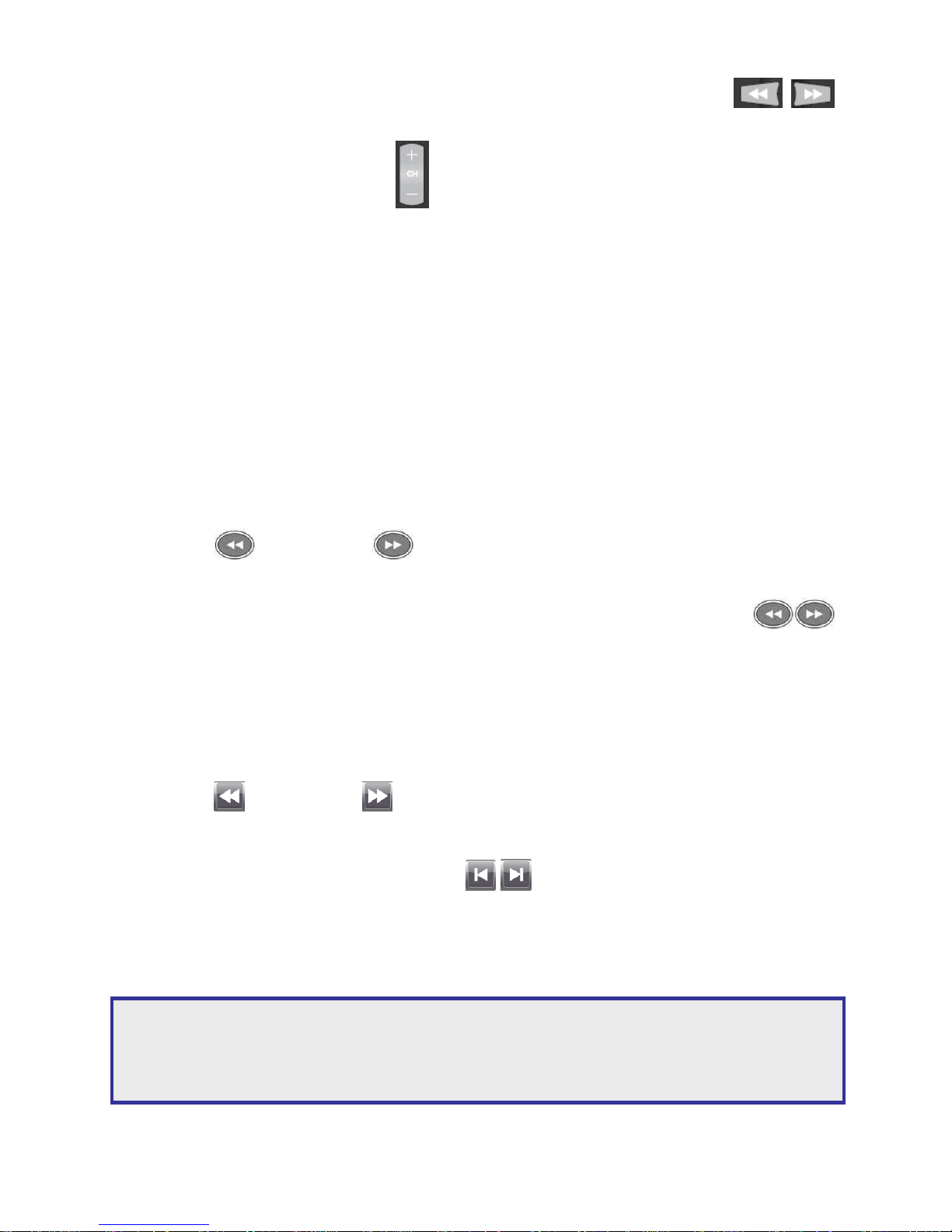
For step rewind/ forward by pressing Pause button then use your controller keys
to move frames
To select individual cameras use
For grid screen view, follow camera selection process.
To turn audio on or off by pressing the Audio key
To activate WYSIWYG backup by pressing Backup
Backup function is commenced if the USB icon light is on
To stop recording by pressing Backup button again
To exit playback by pressing Stop or Escape button
c. Via keyboard
Use keyboard keys to play, stop, or pause
Use button to rewind. Use to fast-forward
Press “2x” once and subsequent press to increase speed
For step rewind / step fast-forward by pressing pause then use your controller keys
to move frames
d. Via touch screen monitor / mouse
Use on screen keys to play, stop or pause
Use button to rewind. Use to fast forward
Press once for 2x and subsequent press to increase speed
For step rewind / step fast-forward, use keys to move frames
To exit playback by pressing Stop or Escape button
To activate WYSIWYG backup, insert USB and press ‘backup’. The USB icon will light to show
backup has commenced. To stop recording, press ‘backup’ again.
Note: For all methods, with WYSIWYG backup, all channels will be exported regardless of on-screen
camera selection. Once backup has been activated, playback will slow down. While playing back the
file with fast-forward featured being selected, the speed will be normal but the frame rate will be
reduced.
Page 23

DVR User Manuel 22
Chapter 8: Alarm Management
Alarm events:
• Motion – created by movement
• Sensor – created by hardwired normally open / normally closed alarm input at the back of
the unit
• Manual – created every time the record button is pressed
a. Via front panel
• To select alarm indicator by pressing Menu and use Left and Right direction keys until correct
icon is reached
• Press Enter to select
• To scroll through alarm events use up and down direction keys
• Choose alarm event and press enter
• Use up and down direction keys to select recorded event
• Use right and left direction keys to select action
b. Via remote control
• To select alarm indicator by pressing Menu and use left and right direction keys until correct
icon is reached
• Press Enter to select
• To scroll through alarm events by using up and down direction keys
• Choose alarm event by pressing Enter
• Use up and down direction keys to select recorded event
• Use right and left direction keys to select action
c. Via keyboard
• To select alarm indicator by pressing Search
• To scroll through alarm events using up and down direction on joystick
• Choose alarm event and press Enter
Note: See installation guide for information on how to set up alarms.
Page 24

DVR User Manuel 23
• Use up and down direction on joystick to select recorded event
• Use right and left direction on joystick to select action
d. Via touch screen monitor
To select alarm indicator touch alarm key located at the top left hand corner of the
screen
Use touch screen interface to select alarm events
Press Load icon to load alarm events
Use up and down scroll bar to select recorded event
Use button to return back to the previous recorded event. Use button to enter the next
recorded event
Press USB, email, playback to select action
Page 25
DVR User Manuel 24
Chapter 9: Backup / Export
Backup methods as following:
• DVD – compatible with DVD+RW, DVD+R, DVD-RW, DVD-R
• USB – USB flash drives are removable, rewritable data storage devices with a Universal
Serial Bus (USB) interface
• Temporary hard drive space – save a backup clip to an area on the DVR hard drive that
will not be overwritten (only one file at a time). To access saved backup clip, use Backup
Manager program or web-based browser viewing
Different actions will provide a different export result:
• Email will send a stationary image
• USB will save a stationary image
• Playback will take you to the selected event on screen
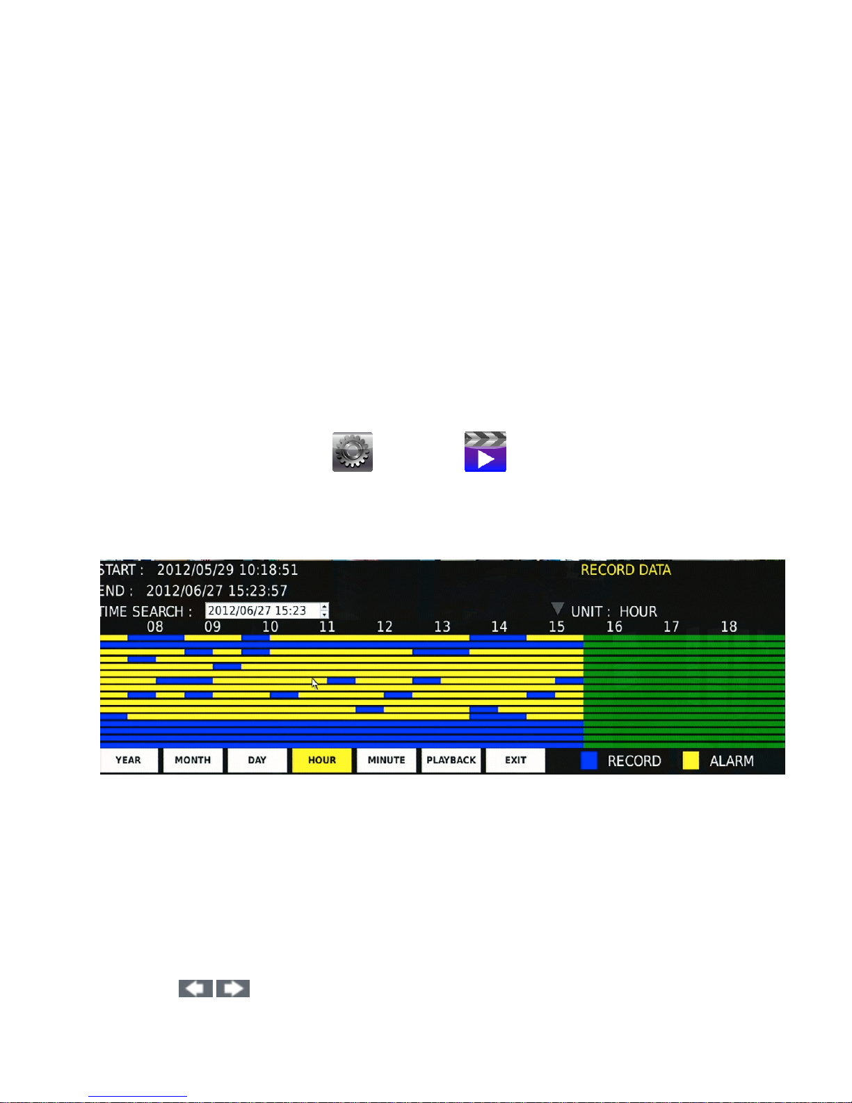
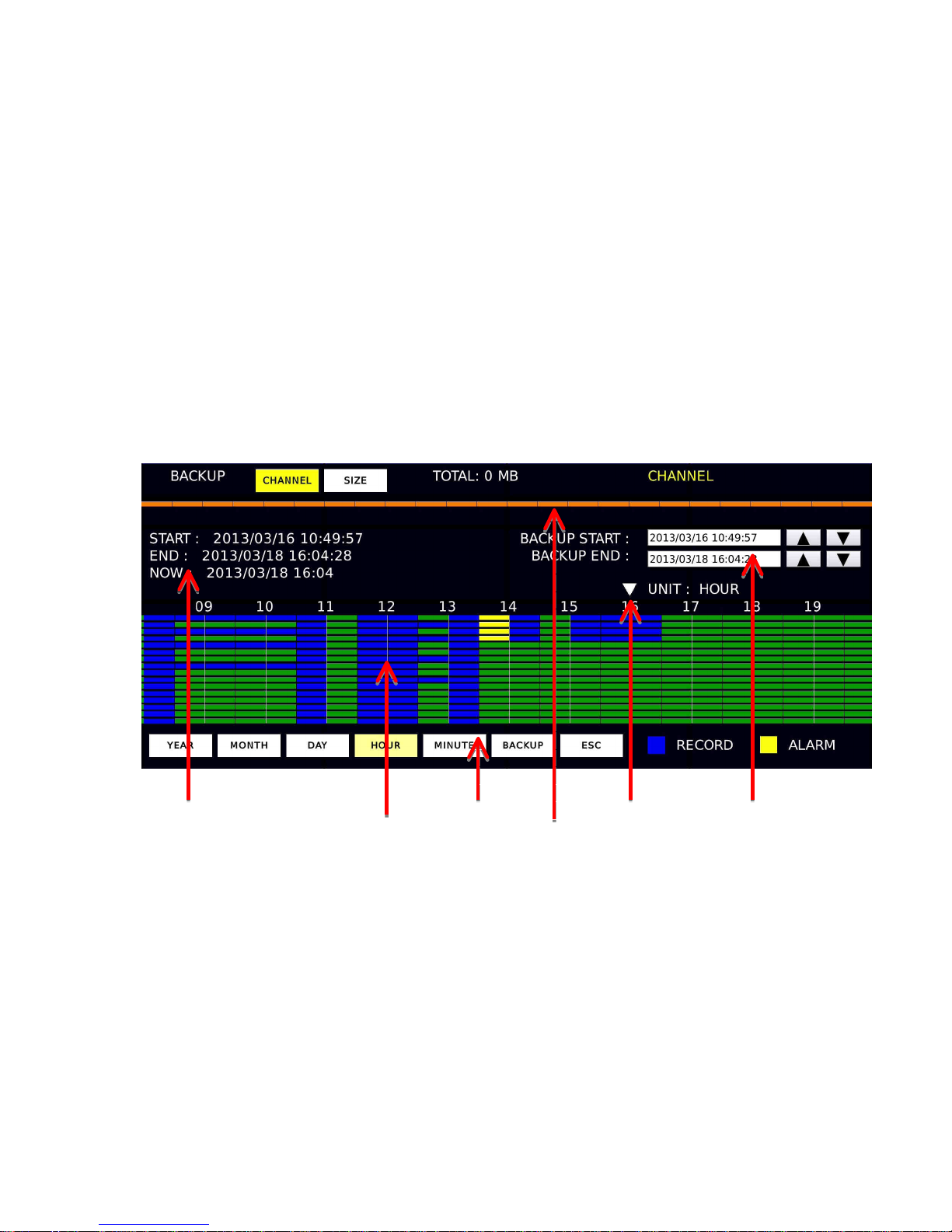
5. Recorded data 2. Time Frame 3. Unit selector 6. Backup data
1. Channels 4. Backup bar
1. 16 bars represent 16 channels. 1 at the top – 16 at the bottom
Colour code:
Yellow = alarm record
Blue = constant record
Green = no record
2. Time frame = year, month, day, hour, minute
3. Unit selector = the down arrow indicates desired selection
4. Back up bar = this is the orange bar that shows the range of your backup
Highlights green when back up section has been chosen
5. All recorded data = start, end, now box
6. All backup data = start, end box
Page 26

DVR User Manuel 25
File formats
• MULTI-CHANNEL exports all attached channels or chosen channel includes backup
manager playback software
• MULTI-CHANNEL AVI exports all attached channels or chosen channel at AVI files
a. Via front panel
Press ‘backup’ key to begin
Use Shift key to toggle between “record data,” “backup range,” and “channel”
Use Shift key to select channel and press Enter
Use Up and Down keys and hit Enter key to select your file format and channel
Use Shift key to select specific recorded data, use Up and Down keys to navigate the time
frame and Left and Right keys to navigate unit selector
For backup range, use left and right keys to navigate, press Enter to create start point.
Use Left and Right keys to determine backup period
Press Enter to complete
Once Enter has been pressed, a backup start and backup end box will appear. If correct, press
the backup key and select export method
Once started backup, the display screen will revert back to live mode, the backup icon will
illuminate and flash with percentage rate
Once completed, the illumination and flashing will stop
b. Via remote control
Press Backup key to begin
Use Shift key to toggle between record data, backup range or channel
Use Shift key to select channel and press Enter and file format and channel use
Press Enter to select your channel
Use Shift key to select recorded data, use to navigate the time frame and
to navigate unit selector
For backup range, use to navigate, press Enter to create start point
Use to determine backup period.
Press Enter to complete
Once Enter has been pressed, a backup start and backup end box will appear
If correct, press the backup key and select export method
Page 27
DVR User Manuel 26
Once backup has started, the display screen will revert to live mode, the backup icon will
illuminate and flash with percentage rate
Once complete, the illumination and flashing will stop
c. Via keyboard
Alternative method required
d. Via touch screen monitor / mouse
Press backup to begin
Select channel by pressing and scrolling toolbar
Navigate time frame via pressing desired period
Select time by dragging unit selector or use pinch-to-zoom technique
For backup range, press orange bar and drag for required time period
Once drag is complete backup start and backup end box will appear
If correct press the backup from time frame bar and select export method
Once backup has started the display screen will revert to live mode, the backup icon will
illuminate and flash with percentage rate
Once complete the illumination and flashing will stop
Note: Ensure file size is less than your backup device capacity when selecting backup time period.
Longer time periods may take more time to calculate.
Page 28
DVR User Manuel 27
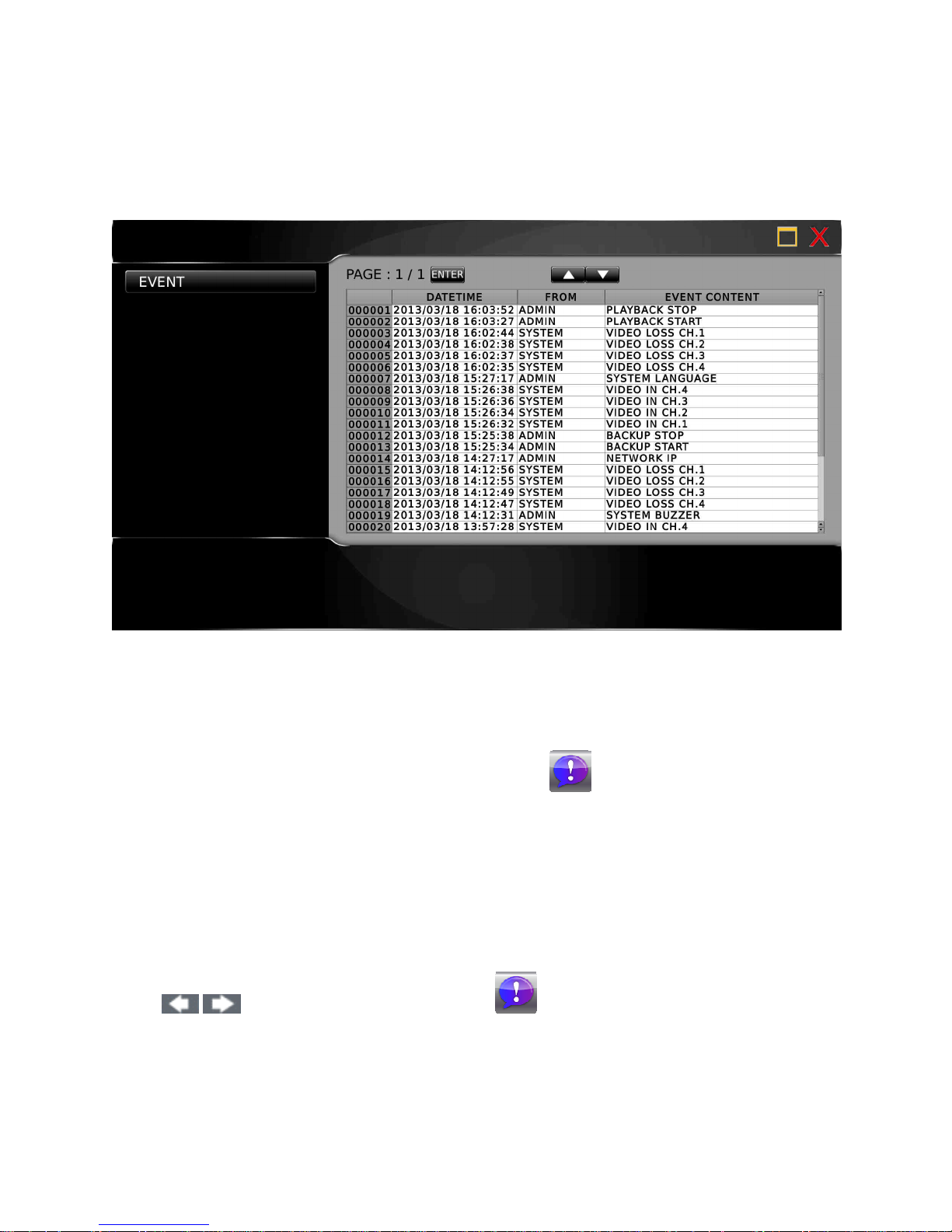
Chapter 10: Event
Within the event menu,
• System event – refers to the systems performance
• Operating event – refers to designated areas selected by the user
a. Via front panel
To access event manager by pressing Menu
Use left and right keys to locate the event manager icon
Press Enter to select
b. Via remote control
To access event manager press Menu key
Use to locate the event manager icon
Press Enter to select
Page 29

DVR User Manuel 28
c. Via keyboard
To access event manager by pressing Set
Use left and rights keys to locate the event manager icon
Press the Enter to select
d. Via touch screen/mouse
To access event manager by pressing the Menu icon
Scroll through the menu to locate the event manager icon
Press enter to select
Page 30
DVR User Manuel 29
Chapter 11: Basic web-based browser viewing
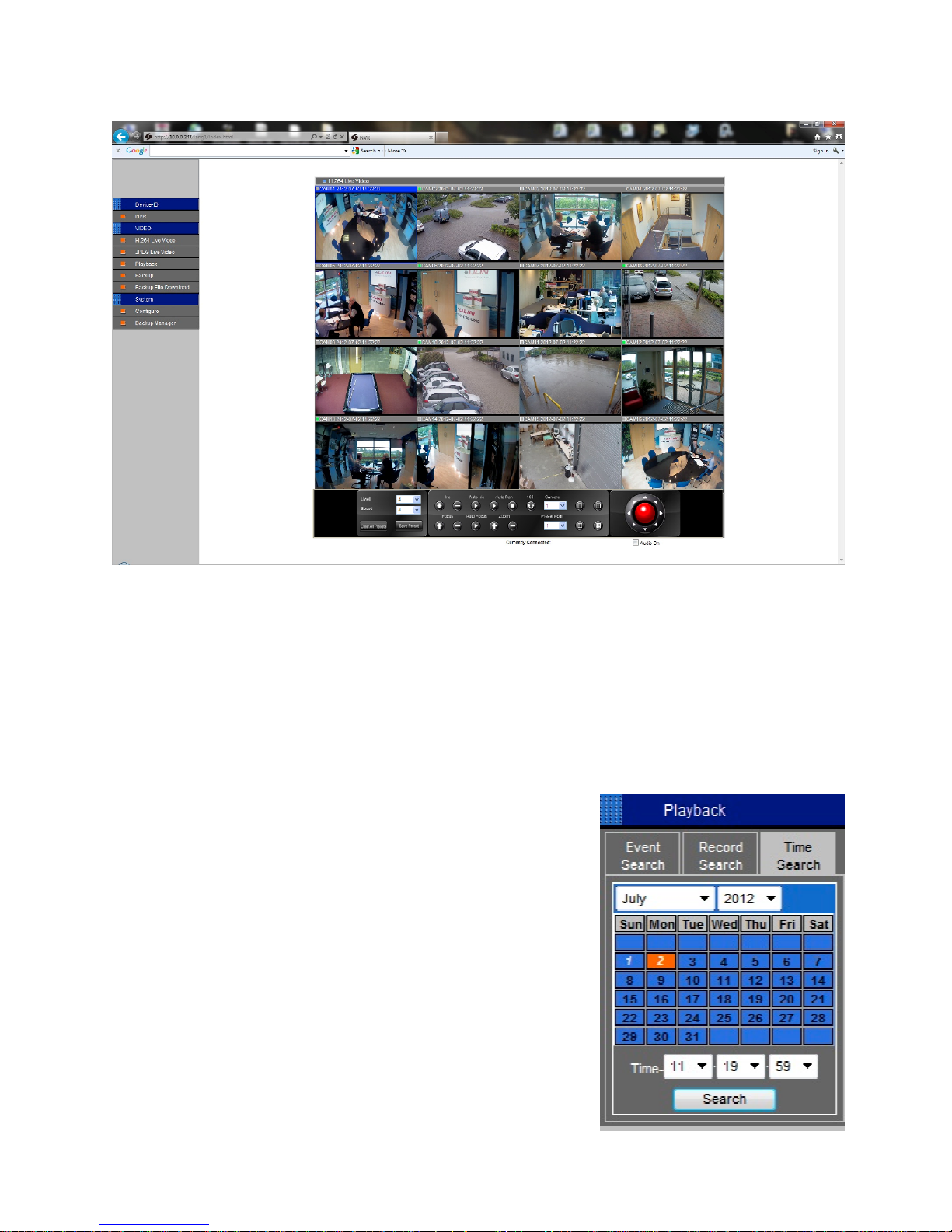
Open Internet explorer and enter the DVR’s IP address into the address bar
The log on screen will appear
Enter your details
The default username is admin, the default password is 1111.
To bring up a full screen double click on required camera view
Double click to return to multi-screen view
11.1 Web-based browser playback
Press the playback button on the left hand side
Choose time and date required in calendar search
Press search to activate
Use the control bar at the bottom of the screen to navigate
playback
The selected recorded images will appear in the multi screen
To return to live mode, press your chosen stream, either
‘H.264 Live Video’ or ‘JPEG Live Video’
Page 31
DVR User Manuel 30
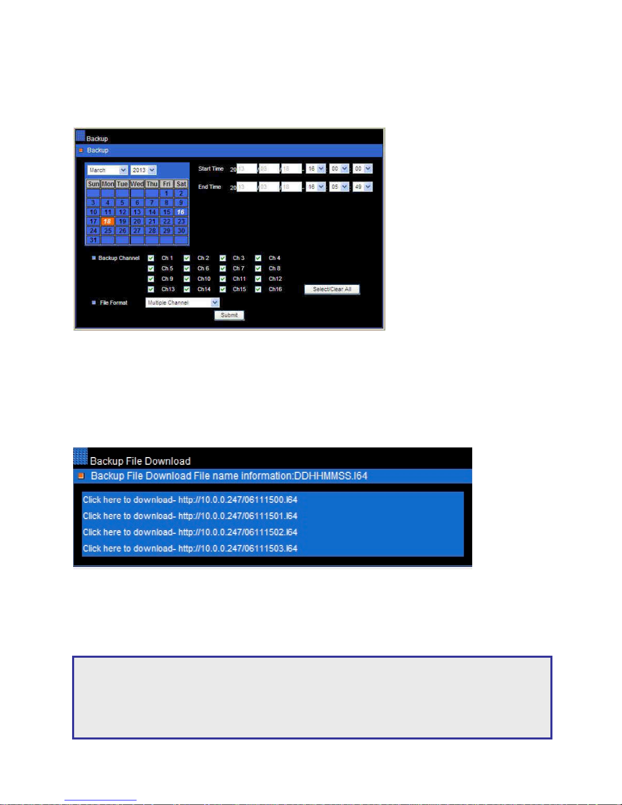
11.2 Web-based browser backup
Press the backup button on the left hand side
Choose date, start time, end time and format required in calendar search
Press submit. A progress bar will appear.
Once complete you will be taken to the backup file download page
11.3 Web-based browser export (backup file download)
Web based browser export applies to either backups created through the browser or through the
temporary hard drive space at the unit
Click required file and save to desired location
Note: To open the downloaded file, you must have the Backup Manager programme installed on
your PC. This can be installed from the front page of your web-based browser. Please see backup
manager section 12.1 for playing exported files.
Only one file at a time is stored. Previous files will be overridden.
Page 32
DVR User Manuel 31
Chapter 12: Backup Manager
Backup Manager is a program provided to playback-recorded files from DVRs and H.264 DVRs
Backup Manager allows you to complete the following actions:
• Playback exported files
• FTP download
• Convert already downloaded files
12.1 Playback exported files
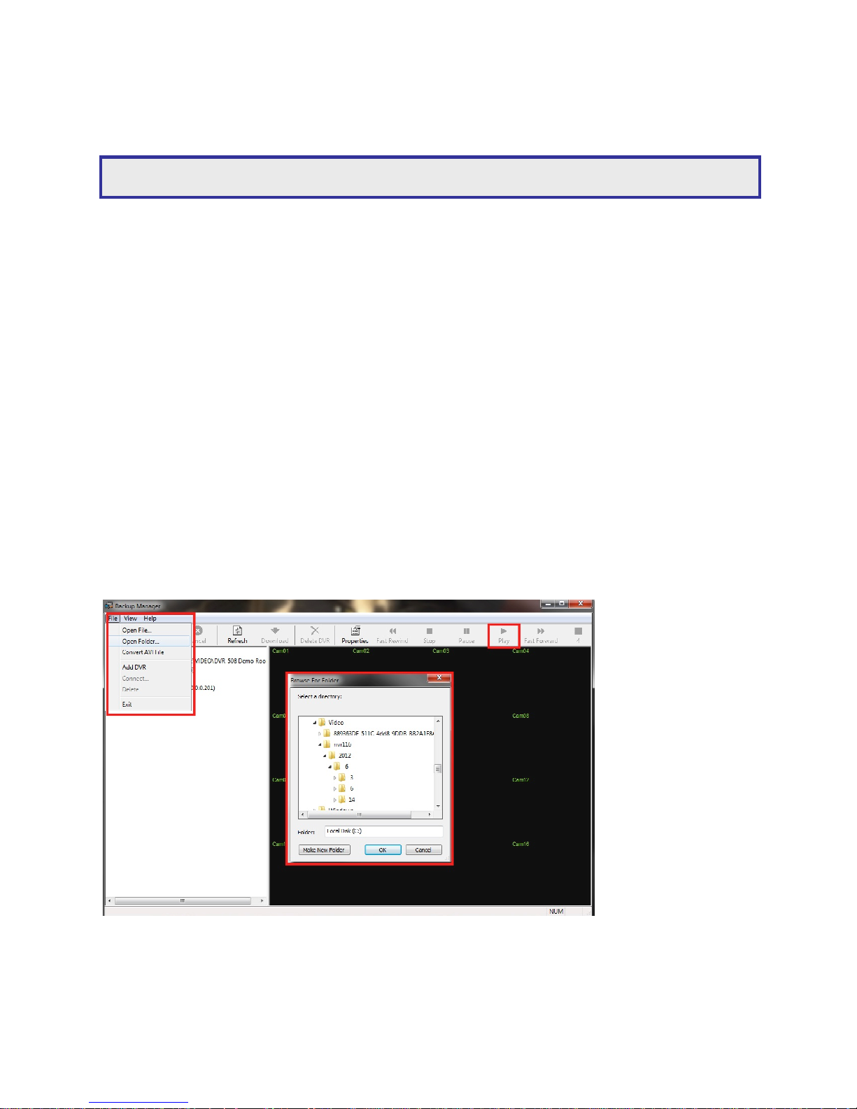
Open Backup Manager
To select files (USB, DVD or web based exported files) click file > open folder
Saved files will then appear
Highlight the desired time from the left hand tree
Press play and use the controls at the top to navigate through playback to change the screen
view
Note: For first time Backup Manager users, please follow the onscreen instructions.
Page 33
DVR User Manuel 32
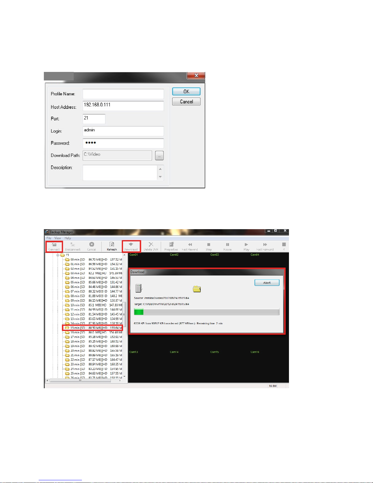
12.2 FTP Download
Open Backup Manager
Click file > Add DVR
Insert the IP address of the DVR
Once the address has been added it will remain stored for future use
Highlight your DVR from the left hand bar and click connect
A download panel will then appear. This means the backup manager programme is
communicating with your DVR gathering all recorded data. Recorded data will appear on the left
hand side. You can access minute breakdowns from the tree.
ADD DVR
Page 34

DVR User Manuel 33
Highlight your required file then click download from the controls at the top
Your files will begin to download
Downloaded files will show in the Backup Manager programme until deleted
12.3 Convert already downloaded files
Backup Manager allows you to convert multi channel backups to single channel AVI files. Please
follow the steps below:
Open Backup Manager
Click file > convert AVI file
Locate desired backup files
Choose the channels you wish to convert. You can select more than 1 channel.
Click OK to start the conversion
The file will now be saved in your desired location
Page 35
DVR User Manuel 34
Quick Installation Guide
This guide has been designed to provide a basic overview of key installation processes. If you
require more detailed instructions, please refer to the full installation guide that follows this
section
Chapter 1: Rear Panel
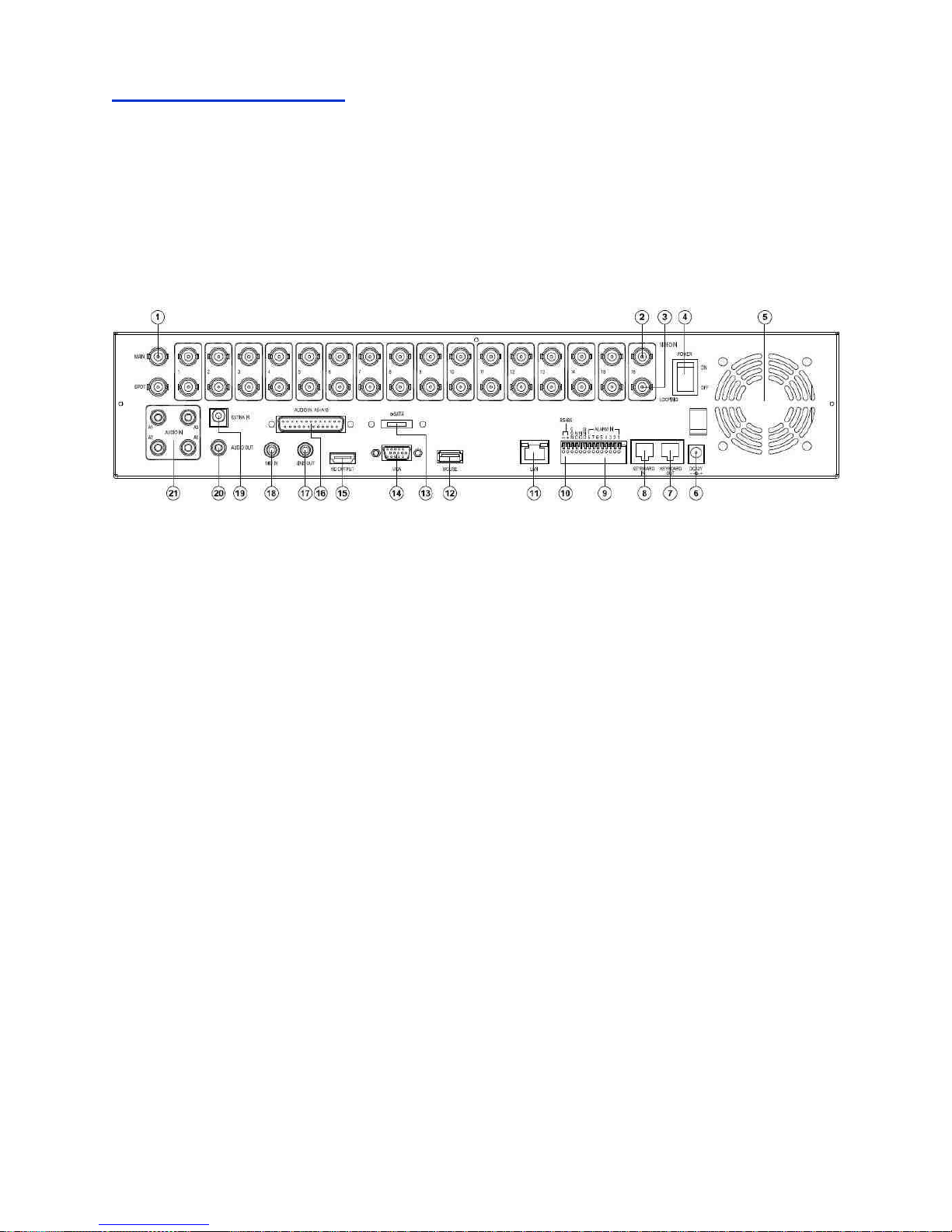
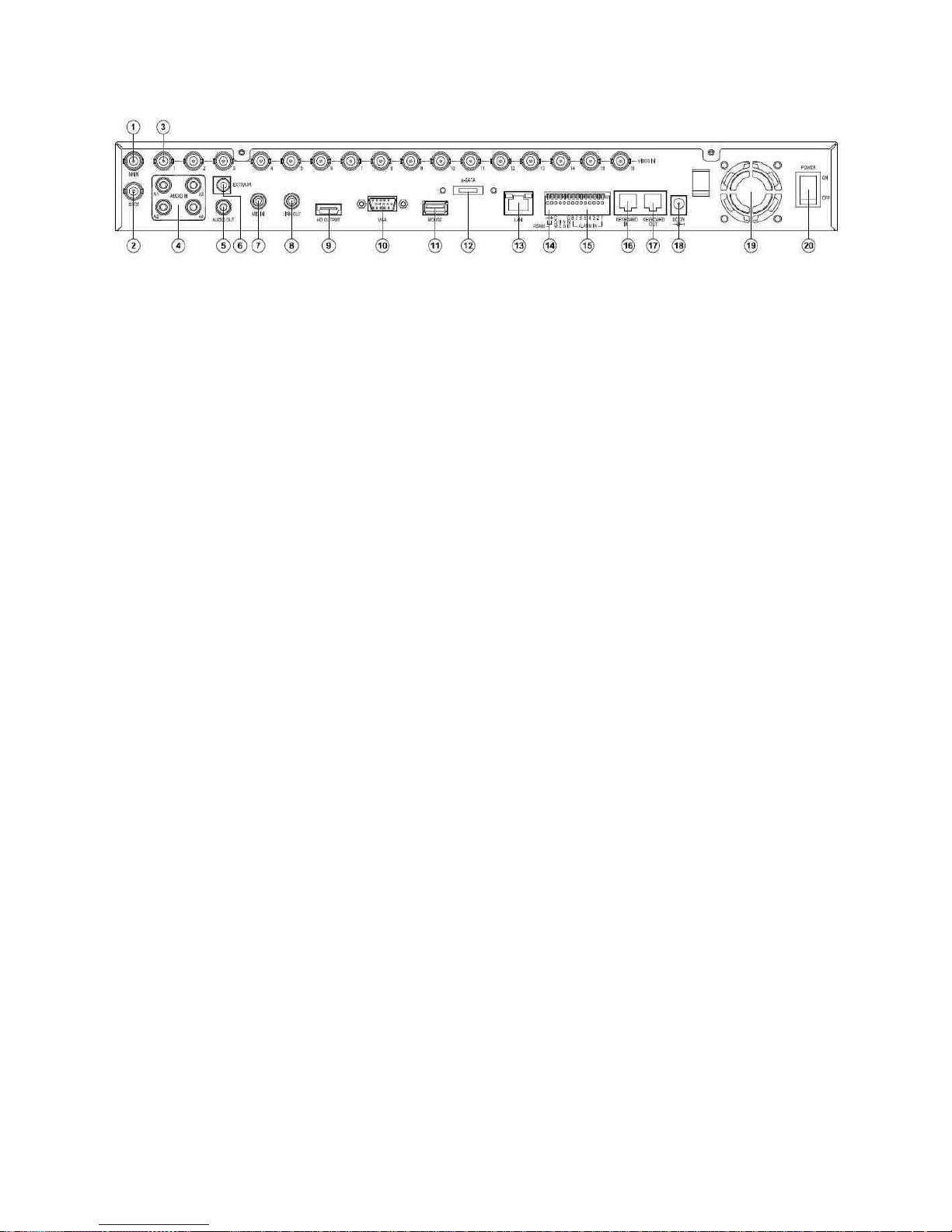
1.1 16CH 2U Rear View
1.
Main monitor
12. USB Mouse
2. Camera inputs
Analog camera BNC 16-inputs
13. eSATA Output
3. Camera Looping
Analog looping BNC 16-outputs
14. VGA Output
4. Power switch
15. HDMI Output
5. FAN 16. Audio Inputs (Audio 5~16)
6. DC 12V input 17. Line Out
7. RJ-45 Keyboard-out
Connect to the next DVR’s input.
RJ-45 connector.
18. MIC In
8. RJ-45 Keyboard-in
Connected from previous DVR’s
keyboard output in daisy chain.
19. External IR receiver
9. Alarm I/Os
Alarm 8 input switches, 1 N/O alarm
output,1 N/C alarm output.
20. Audio Output
RCA audio connector
10. RS485
For PTZ connection.
21. Audio Inputs
RCA audio connectors
11. LAN
Network RJ-45 connector
22. Spot Monitor
a. Spot monitor accessible by keyboard.
b. Each spot output can be programmable
for alarmed camera display and
sequence display.
Page 36
DVR User Manuel 35
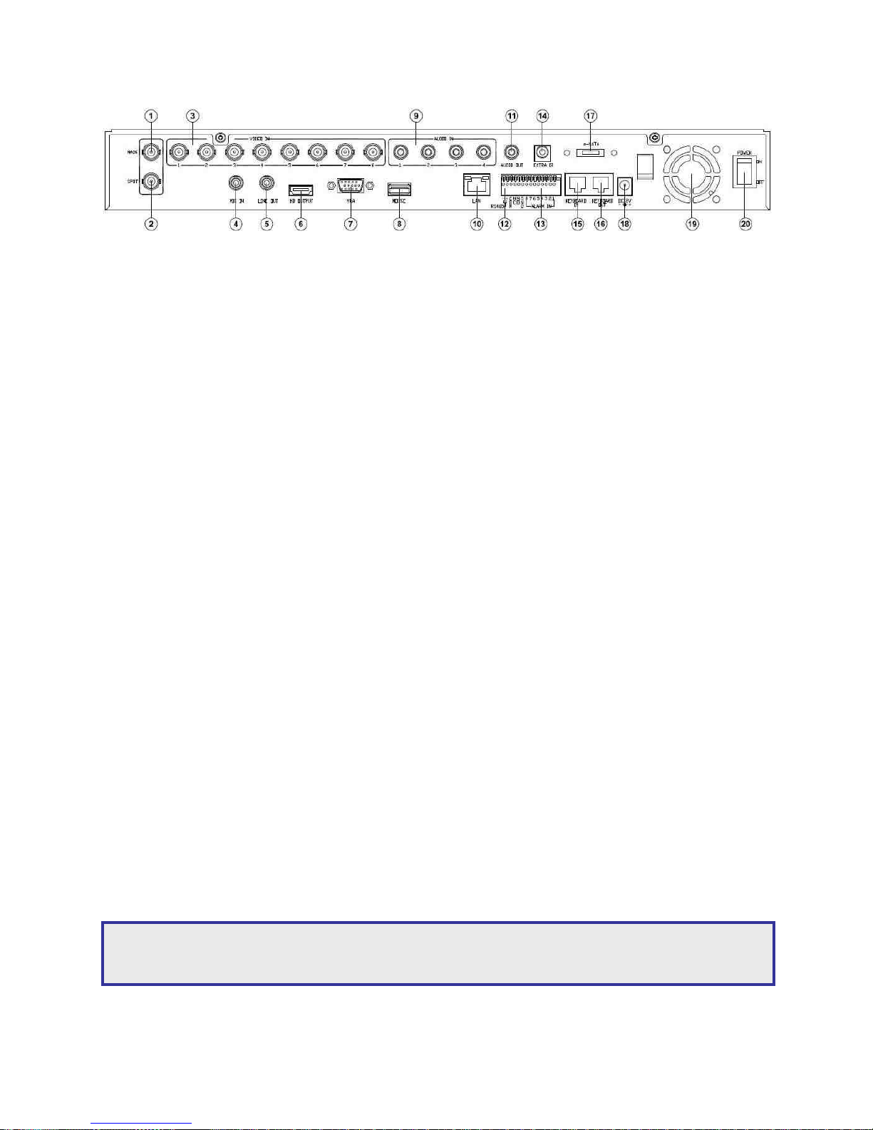
16CH 1U Rear View
1.
Main monitor
11. USB Mouse
2. Spot Monitor
a. Spot monitor accessible by
keyboard.
b. Each spot output can be
programmable for alarmed camera
display and sequence display.
12. eSATA Output
3. Camera Inputs
Analog camera BNC 16-inputs
13. LAN
Network RJ-45 connector
4. Audio Inputs
RCA audio connectors
14.
RS485
For PTZ connection.
5. Audio Output
RCA audio connector
15. Alarm I/Os
Alarm 8 input switches, 1 N/O alarm
output, 1 N/C alarm output.
6. External IR receiver 16. RJ-45 Keyboard-in
Connected from previous DVR’s
keyboard output in daisy chain.
7. MIC In
17. RJ-45 Keyboard-out
Connect to the next DVR’s input.
RJ-45 connector
8. Line Out
18. DC 12V input
9. HDMI Output
19. FAN
10. VGA Output
20. Power switch
Page 37
DVR User Manuel 36
1.2 8CH Rear View
1.
Main monitor
11. Audio Output
RCA audio connector
2. Spot Monitor
a. Spot monitor accessible by
keyboard.
b. Each spot output can be
programmable for alarmed camera
display and sequence display.
12. RS485
For PTZ connection.
3. Camera Inputs
Analog camera BNC 8-inputs
13. Alarm I/Os
Alarm 8 input switches, 1 N/O alarm
output, 1 N/C alarm output.
4. MIC In
14. External IR receiver
5. Line Out
15. RJ-45 Keyboard-in
Connected from previous DVR’s
keyboard output in daisy chain.
6. HDMI Output 16. RJ-45 Keyboard-out
Connect to the next DVR’s input.
RJ-45 connector
7. VGA Output
17. eSATA Output
8. USB Mouse
18. DC 12V input
9. Audio Inputs
RCA audio connectors
19. FAN
10. LAN
Network RJ-45 connector
20. Power switch
Connect power supply, monitor, network cable and control device
Note: For easy installation, it is recommended that you connect a touch screen monitor or USB
mouse.
Page 38
DVR User Manuel 37
Chapter 2: Hard Drive(s)
2.1 Adding hard drive(s)
Please ensure unit is switched off
Open unit by removing side and rear screws
Add hard drive(s) using the supplied mounting screws and sata/power cables
Power Unit
Power up unit by turning the switch on the rear to on
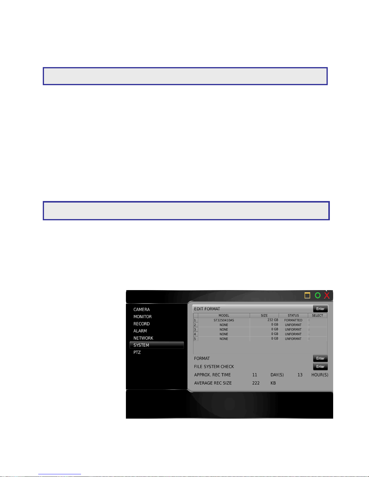
2.2 Formatting Hard Drive(s)
Enter the setup menu
Select system from the left hand options
Select HDD info
Installed drives will be listed
Select drive(s) to format
Select enter
Select OK to complete
Note: If you have purchase a unit with a hard drive installed, please ignore sections 2 and 3.
Note: See user guide for how to navigate the system, i.e. menu’s, camera selection etc.
Page 39
DVR User Manuel 38
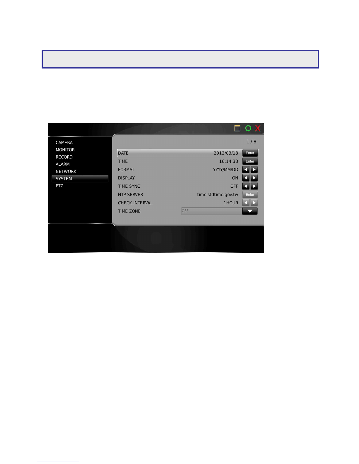
Chapter 3: Time and Date Settings
Enter the setup menu
Select system from the left hand options
Select date/time
Adjust time and date
Select display format
Note: See user guide for how to navigate the system, i.e. menu’s, camera selection etc.
Page 40
DVR User Manuel 39
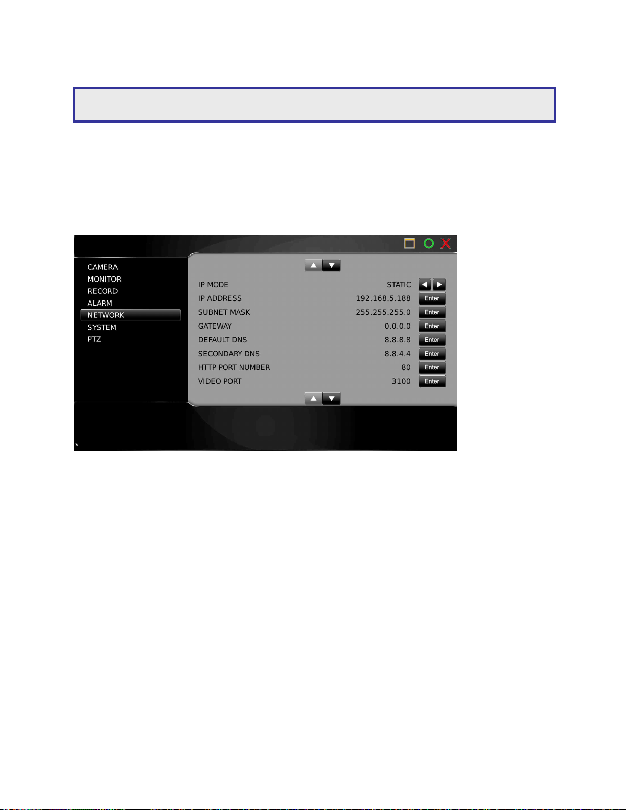
Chapter 4: Network Settings
Enter the setup menu
Select network from the left hand options
Ensure static is displayed under IP mode
Enter your IP address and subnet mask range
Note: This guide will refer to a static IP address. For other options, see installation manual.
Page 41
DVR User Manuel 40
Menu configuration
Chapter 1: Setup Menu
The setup menu contains menu settings for cameras, monitors, recording, alarm, system,
network, and PTZ. The details of all the setup menu items are described in this chapter.
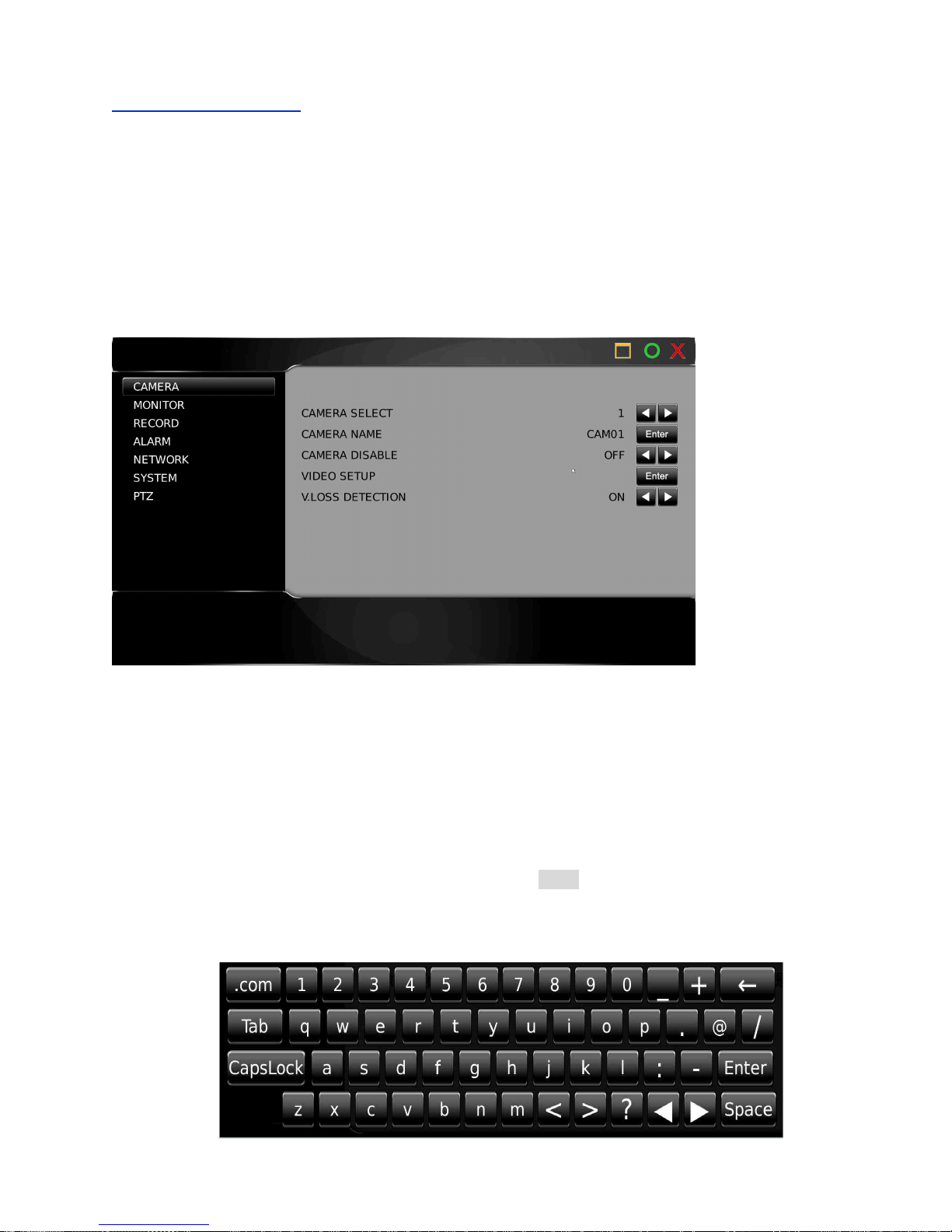
1.1 Camera setup
To setup the camera, use the following steps:
1.1-1 Camera select
Use the directional arrows to select camera you wish to edit/add
1.1-2 Camera name
A user can enter up to 16 characters for a camera name. To setup the camera name, type the
characters using the virtual keyboard and then press the Enter button
Virtual keyboard:
Page 42
DVR User Manuel 41
1.1-3 Camera Disable (Secured Recording Channel)
Channel enable feature can disable the live video of a camera. The channel can still perform
video recording. For privacy or security considerations, irrelevant people may be prohibited to
see the live video.
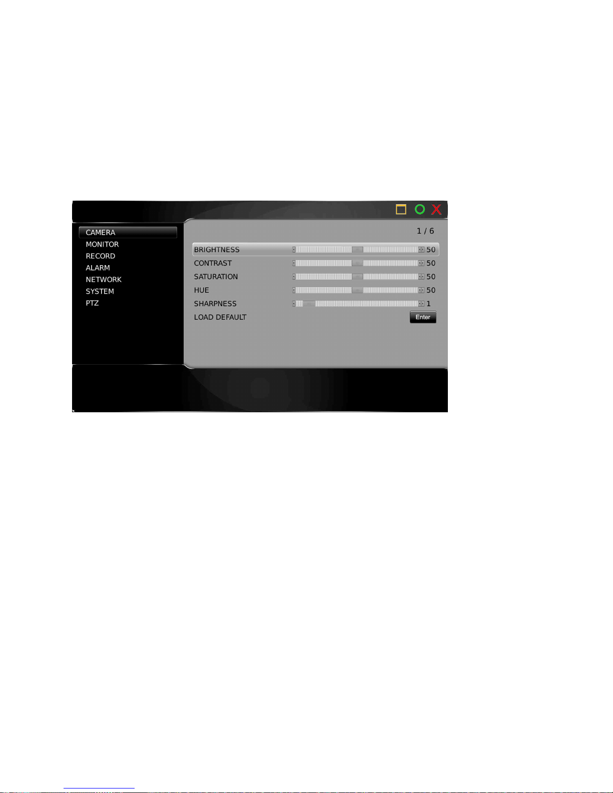
1.1-4 Video Setup
Brightness, contrast, saturation, hue, sharpness and load default are configurable per camera
1.1-5 Video Loss Detection
To enable or disable video loss detection, please set this option to be On or OFF. If the
video signal is unstable and causes video loss, a user can disable this option. Unstable
video signal may generate thousands of video loss events in one second. Temporarily
turn this option Off is able to improve DVR system performance.
Page 43
DVR User Manuel 42
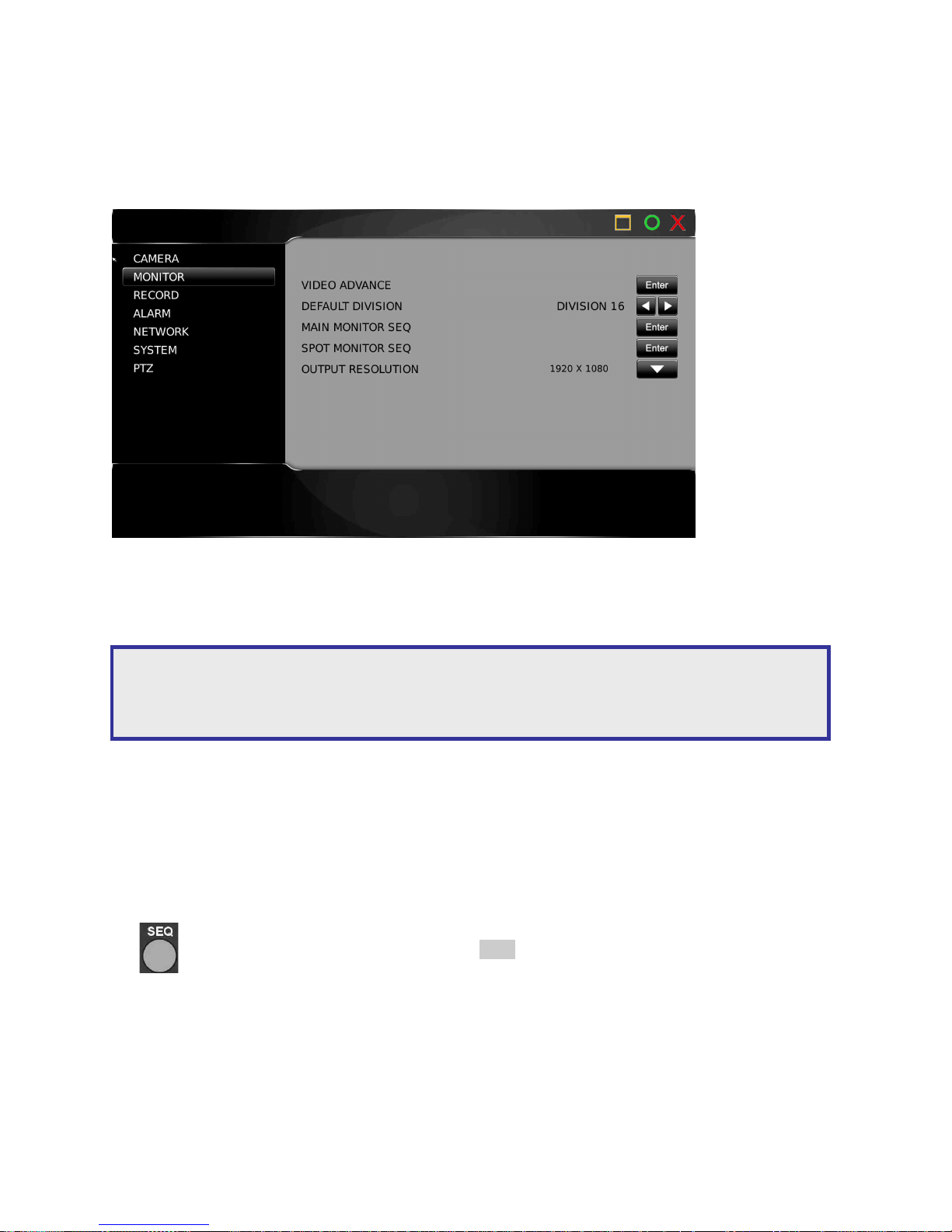
1.2 Monitor Setup
For setting up HDMI, VGA, follow these instructions
1.2-1. Video advance
To setup brightness, contrast, saturation and hue of a HDMI and VGA LCD monitor
1.2-2 Default division
To select the default screen layout/display on power initialize
1.2-3 Main Monitor SEQ
Sequence feature can multiplex each camera screen in full size in specific time period.
Once the sequence time is set, press SEQ button on the remote controller or the
keypad to activate the sequence feature.
The main monitor output can be configured in displaying camera’s full screen. To enable this
feature, please select the camera in camera selection box and alarm switching time.
Note: Different HDMI cables can successfully send HDMI signals various distances, depending on
the quality of the HDMI cables design and construction. It is best to test entire systems before
installing, recommended the HDMI cable length is 2 meters.
Page 44
DVR User Manuel 43
1.2-4 Spot Monitor SEQ
To setup the sequence, please first assign SEQ MODE for output. Specify SEQ TIME in seconds. Once
above has been setup, spot monitor starts to perform sequence display.
The spot monitor output can be configured in displaying camera’s full screen. To enable this
feature, please select the camera in camera selection box and alarm switching time.
1.2-5 Output resolution
Set accordingly to match your HDMI and VGA monitor resolution
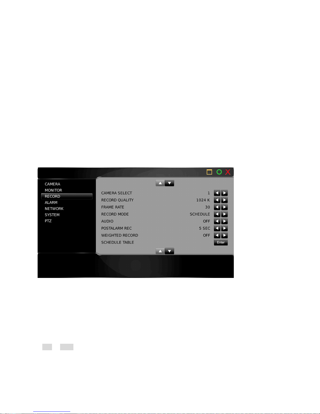
1.3 Record setup
Record setup menu allows for setting recording features such as record quality, frame rate,
record mode, audio selection, alarm recording, schedule table, HDD overwritten, and limited
recording
1.3-1 Camera select
Use the directional arrows to select camera you wish to configure
1.3-2. Record quality
The recording quality can be configured for each channel. To change the quality setting, press
Left or Right button.
Page 45
DVR User Manuel 44
1.3-3 Frame Rate
Each Camera can be set to the desired frame rate. Use the directional arrows to select frame
rate you wish to configure
1.3-4 Recording mode
Each camera can be set for schedule recording or no recording
1.3-5 Audio
To enable audio recording this feature must be turned on
1.3-6 Post-alarm Recording
Post-alarm recording records the video of a camera after a particular alarm/motion is triggered.
This can be set between 1-100 seconds.
1.3-7 Weighted recording
When weighted recording is activated, the standard camera recording frame rate is increased
to the pre-determined rate (set in advance recording), once an alarm is detected by DVR.
Without an alarm the camera will record at 1FPS.
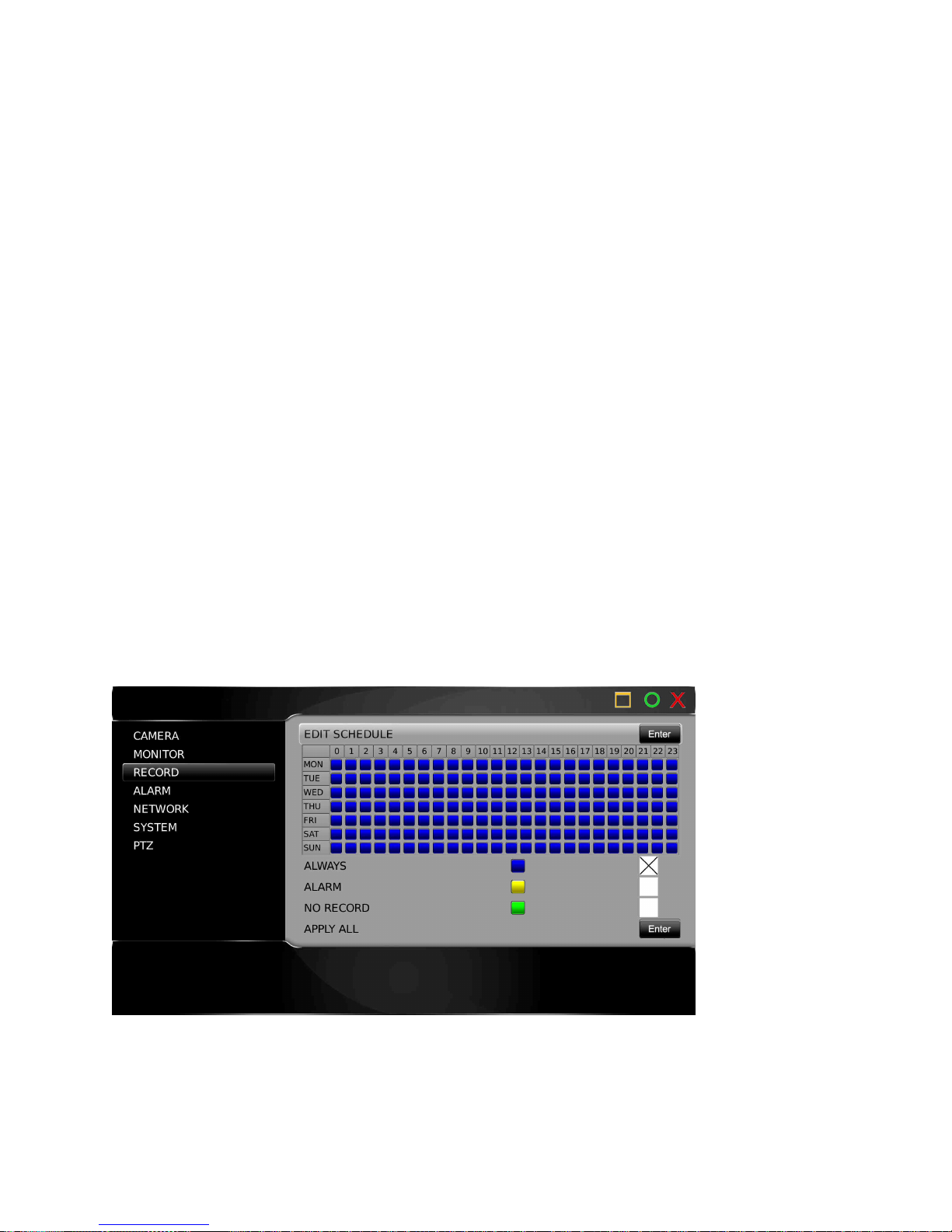
1.3-8 Schedule table
Page 46
DVR User Manuel 45
The schedule table is displayed as hourly intervals 7 days a week. You can chose whether you
want the DVR to record constantly (always), on an alarm event (alarm) or not record (no
record). Your chosen method is indicated by a colour code on the time/date grid.
1.3-9 HDD overwritten
The DVR can be setup for HDD overwrite. If the user does not want the HDD to be overwritten,
turn the option off.
1.3-10 Limited recording
In many countries HDD recording may be limited and can be only accessed for a certain period
of time. Once the recorded data passes the chosen period, the data can no longer be accessed.
Set your desired period here (in days).
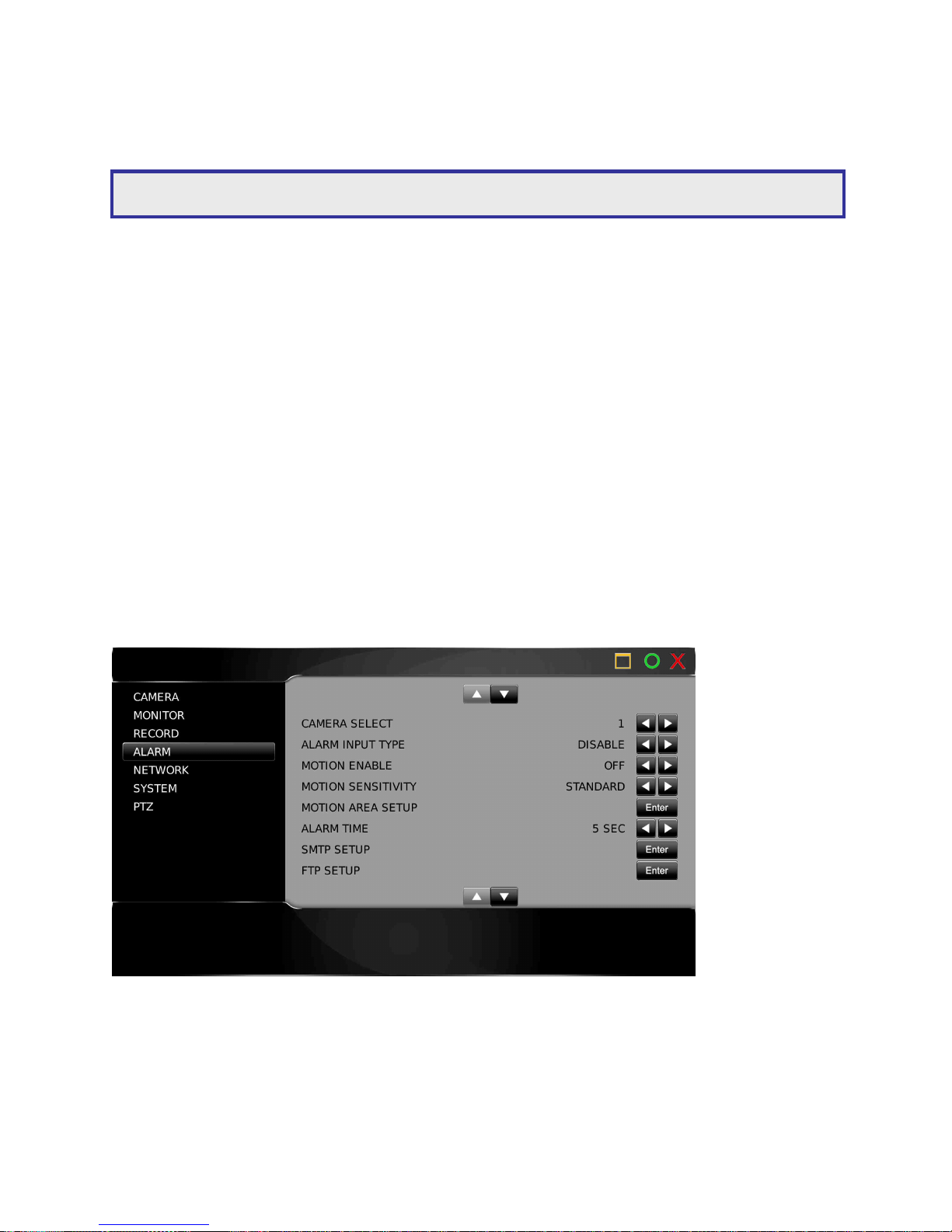
1.4 Alarm setup
Alarm setup menu allows the settings of external alarm switches, motion alarm, buzzer, and
alarm recording duration to be changed. To change these settings, enter the Alarm setup menu
and follow the instructions:
1.4-1 Camera select
Use the directional arrows to select camera you wish to configure
Warning: The schedule table is a universal table and changes will apply to all cameras on the DVR.
Page 47
DVR User Manuel 46
1.4-2 Alarm input type
The DVR's alarm inputs can be configured as normally open (N/O) or normally closed (N/C) for
IP cameras where the alarm signal from an IP camera activates an alarm.
1.4-3 Motion enable
Motion Enable enables motion alarm recording, after the motion detection area (‘Motion Area
Setup’) has been set. Press Left or Right at Motion Enable to change the setting.
1.4-4 Motion sensitivity
There are eight levels of sensitivity adjustable for motion alarm triggering, ranging from
‘Highest’ to ‘Lowest’. Press Left or Right to change the sensitivity setting.
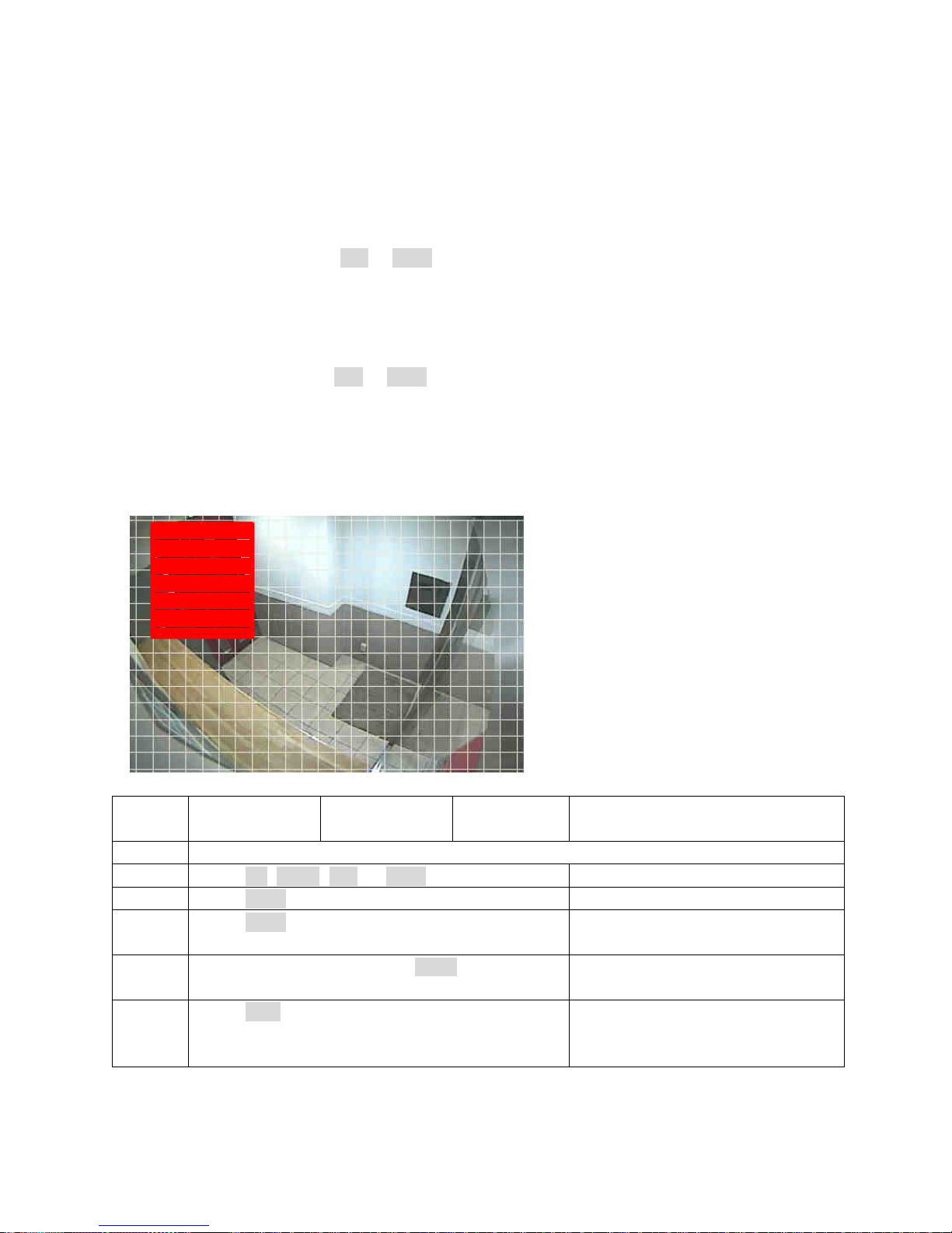
1.4-5 Motion area setup
There are a number of ways to set the motion detection area. The detailed setting sequence is
described as follows:
Keypad Keyboard Remote
controller
Mouse
Step 1 Enter Motion Area Set menu item.
Step 2 Press Up, Down, Left, or Right to move cursor Move mouse for starting position
Step 3 Press Enter to define starting area
Step 4 Press Enter again to finish a motion detection
zone
Mouse-drag for an area
Step 5 To clear motion zones press Menu button Double-click for clear motion
zones
Step 6 Press ESC for exit the setting menu Move mouse to “X” icon and
press Left-mouse click to exit
motion zone setting
Red indicates motion area
Page 48

DVR User Manuel 47
1.4-6 Alarm time
Set the period of time 1-100 seconds the alarm output relay is triggered upon an alarm event
1.4-7 SMTP setup
DVR is capable of sending JPEG snapshots to an email account when an alarm event is
triggered. To enable this feature, you must type in the relevant email account information.
1.4-8 FTP setup
The DVR is capable of alarm snapshot to an FTP server. To enable this feature, you must type
in the relevant FTP account information.
1.4-9 Buzzer timer
Select a time period you wish the buzzer (on DVR) to sound for upon an alarm trigger. This can
be set between 1-100 seconds, it can be set to always or off as required.
1.4-10 Buzzer enable
Turns the audible warning buzzer (on DVR) on or off
1.4-11 Button sound
Enables or disables button sounds on DVR
1.5 Network setup
In order to connect the DVR to LAN or the Internet you require subnet mask, gateway and IP
address. Consult your system administrator for more information.
It is highly recommended that DVR’s are accessed on a high bandwidth network such as
Gigabit LAN.
Page 49
DVR User Manuel 48
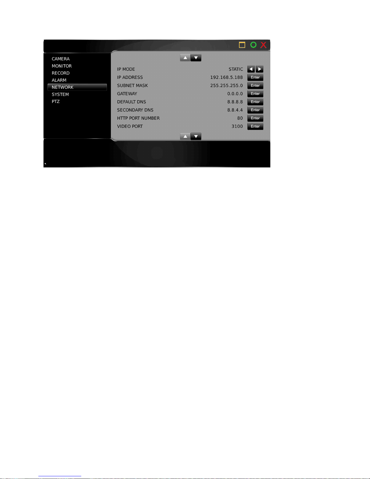
1.5-1 IP mode
Set the DVR to Static, DHCP, and PPPoE IP modes. It is highly recommended that DVR’s are
accessed on high bandwidth network such as Gigabit LAN’s.
1.5-2 IP address
Enter the IP address for the DVR using the virtual keyboard
1.5-3 Subnet mask
Enter the Subnet Mask for the network using the virtual keyboard
1.5-4 gateway
Enter the Gateway address for the network using the virtual keyboard
1.5-5 Default DNS
Enter the Default DNS address for the network using the virtual keyboard
1.5-6 Secondary DNS
Enter the Secondary DNS address for the network using the virtual keyboard
Page 50
DVR User Manuel 49
1.5-7/8 HTTP Port Number and Video Port Number
For Internet connection, port number IP mapping technologies can be used for a single IP
address shared by multiple devices, via a network router. Consult your network administrator
for this advanced network support. HTTP Port number is the web service port number of the
DVR
1.5-9 FTP Port Number
DVR has a built-in FTP server. The FTP service is also used by Backup Manager.exe. Backup
Manager can manage all the DVR’s playback clips via a network.
1.5-10 MAC
Display the MAC address of the DVR
1.5-11 PPPoE IP
Enter IP address
1.5-12 DDNS
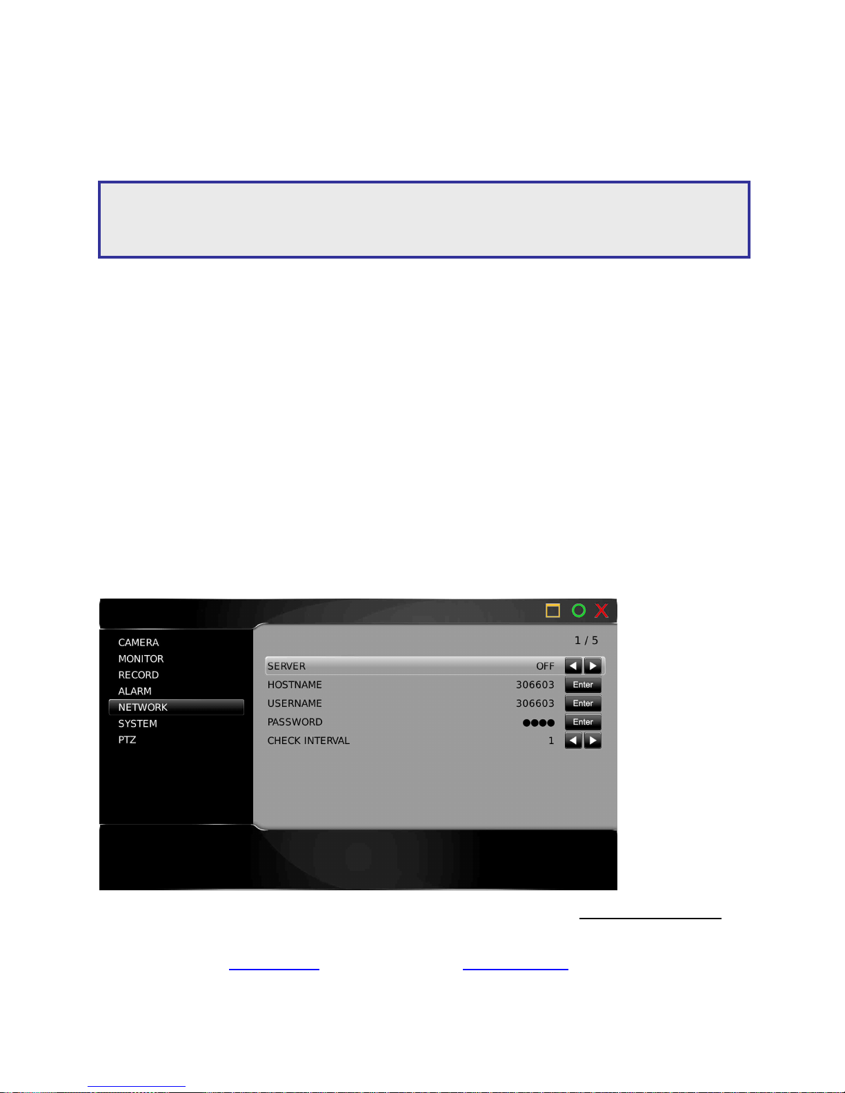
If your DVR has Internet access it will automatically try and register at www.ddnsipcam.com. It
will automatically use the last 5 digits of the DVR’s MAC address as the host name.
For access enter http://10685D(last 6 digits of MAC).ddnsipcam.com into your browser
Login to the DVR with your default user name and password
Note: Default Internet port numbers for the DVR are:
Port 80 (HTML web page)
Port 3100 (video port)
Page 51
DVR User Manuel 50
1.5-13 PPPoE
To use ADSL modem, enter “username” and “password” provided by the Internet Service
Provider (ISP) for the Internet connection service.
1.6 System setup
To set up the system settings, use the following instructions:
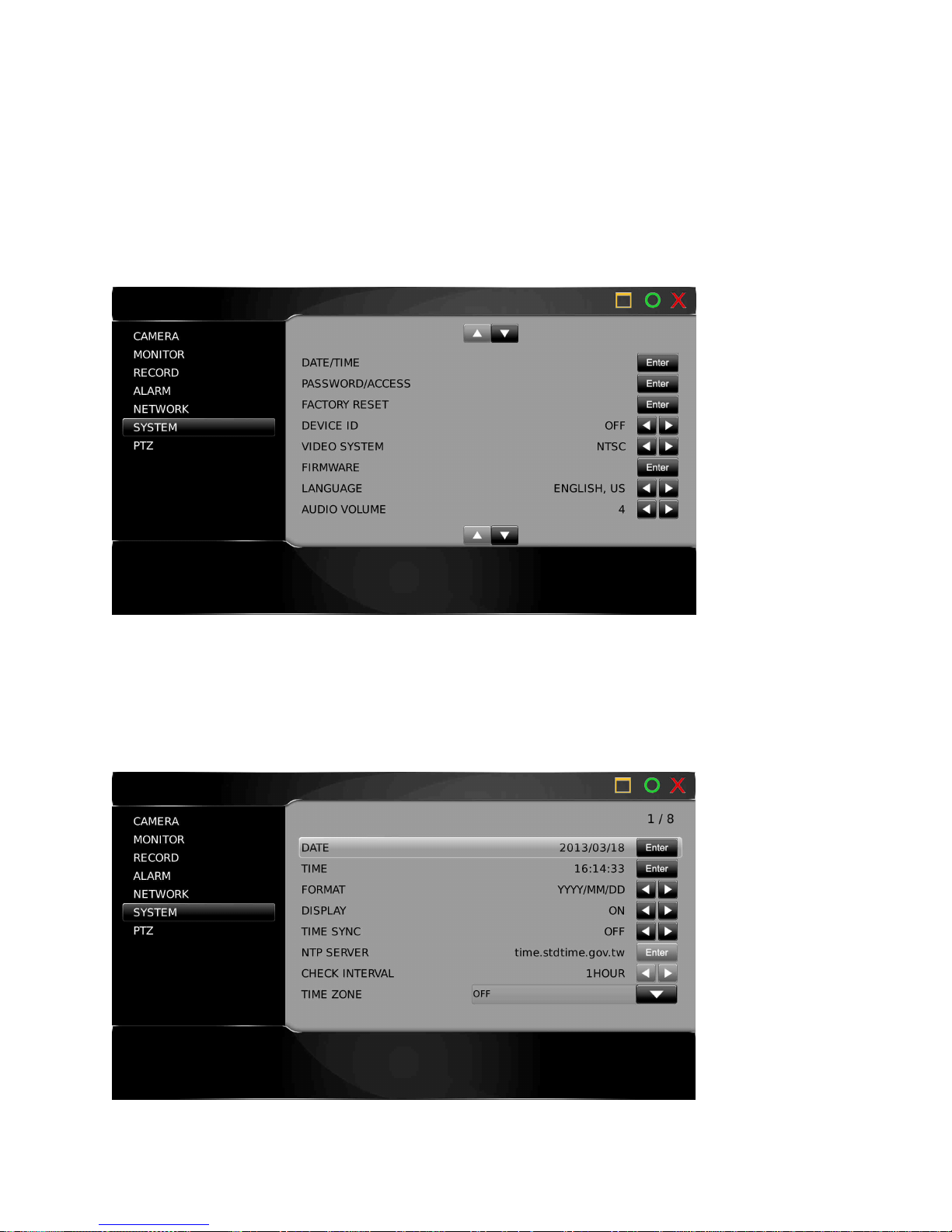
1.6-1 Date/Time
Press enter to set Date/Time on the DVR. The display format can also be set here. If a
Keyboard is connected time Sync can be set, the DVR will then sync its time from the keyboard
every 15 minutes. Or a NTP (network time protocol) server can be selected.
Page 52
DVR User Manuel 51
1.6-2 HDD Info
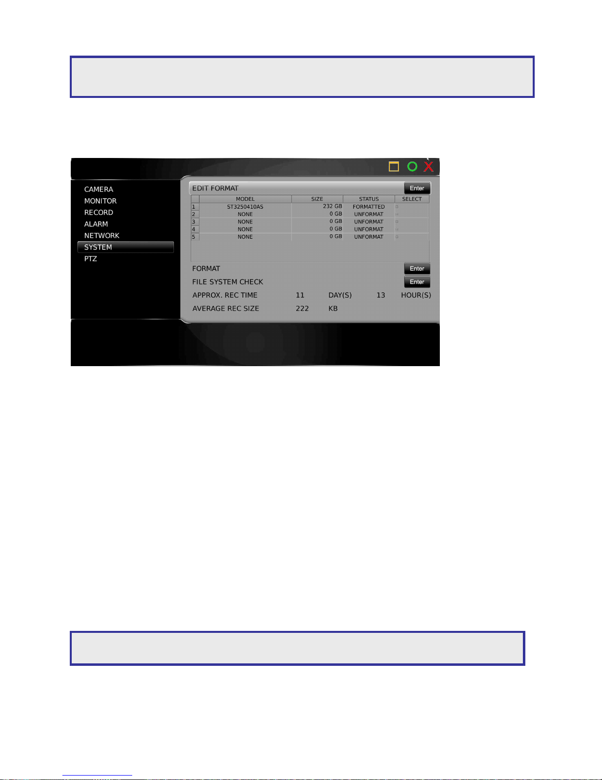
HDD INFO shows the following information:
• Model — HDD model
• Size —the capacity of the hard disk drive
• Status — indicates whether the HDD is formatted or unformatted
• Select — “□“ indicates that the HDD is selected
• Approximate recording hour—recording hours based on the HDD(s)
• Approximate recording days—recording days based on the HDD(s)
• Average REC size—average recording data size
HDD Format
Select the HDD(s) you wish to format, select the HDD format menu item. A password is
required for preventing unauthorized access.
A warning message will also prompt you for formatting verification
Warning: When time & date is changed, existing footage already recorded in that time range will
be lost.
Warning: Formatting a HDD will erase all recorded data on that drive.
Page 53

DVR User Manuel 52
File system check
This function allows you to perform a file system check and repair of the HDD. If a HDD is
reported to be defective, run the system check function.
1.6-3 Password/Access
The DVR can be configured for up to 15 users with different access rights
Scroll to select between:
Admin (default password 1111)
Operator (default password 2222)
Guest (default password 3333)
Users 1 to 12
Once a user is selected you can edit passwords, enable password protection and set up the
following user rights:
• Allow Setup
• Allow Playback
• Allow PTZ
• Allow Backup
• Allow Division
• Allow Shutdown
• Allow Alarm
• Allow Shortcut
• Allow Network Setup
• Allow Network Playback
1.6-4 Factory reset
A user may want to restore manufacturing default settings. A confirm message will show for
final verification. To perform this task, select Factory Reset at System > Factory Reset and
press Enter.
1.6-5 Remote device ID for remote control
Each DVR can be assigned a unique DVR ID to be accessed by the remote controller. With a
unique DVR ID set, the remote controller issues commands to a particular DVR. The rest of
DVRs are in sleep mode
Note: In the event of a forgotten password, please contact your sales agent.
Note: Factory reset does not affect IP address, video system, and language settings.
Page 54
DVR User Manuel 53
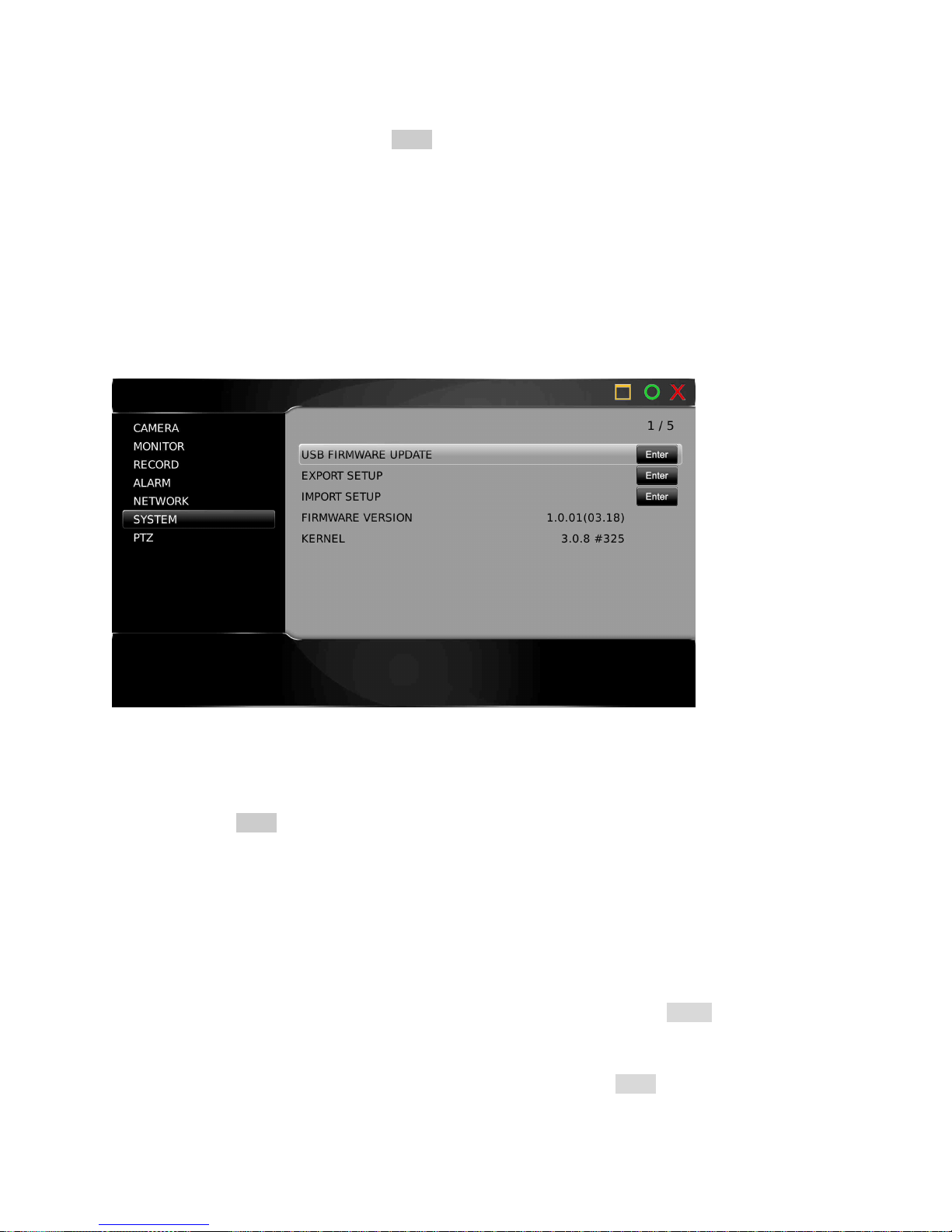
1.6-6 Firmware update
Firmware update allows you to upgrade the DVR’s firmware for improving system performance.
To perform firmware update, press Enter on Setup > System > Firmware Update. There are
two ways to perform firmware update (1) via USB flash disk at the DVR site (2) via HTML
interface via network
Prepare firmware
To prepare a firmware update, create a directory called ‘firmware’ in the USB flash disk. The
USB flash disk should use the file system FAT-16 or FAT-32. The firmware name of the 16CH
(2U) is ‘FlashDVR816.bin’. The firmware name of the 16CH (1U) is ‘FlashDVR716.bin’. The
firmware name of the 8CH is ‘FlashDVR708.bin’.
To perform firmware update using USB flash disk, follow the instructions:
1. Plug in a portable USB disk at the DVR’s USB port
2. Press Enter to start firmware update
3. After the transfer has finished, remove the USB device and reboot the DVR.
4. Ensure that the firmware is located in the firmware directory of the USB disk
Export setup
The export setup feature allows a user to export internal configuration into a system file on the
USB flash disk’s firmware directory. The file can later be imported to other machines. The
imported machine’s internal configuration gets updated based on the original DVR’s
configuration. To perform Export Setup, select ‘Export Setup’ and press Enter.
Import setup
To perform Import Setup feature, select ‘Import Setup’ and press Enter.
The configuration of the DVR is updated based on the system file
Page 55
DVR User Manuel 54
Firmware and kernel version
Version menu item indicates the current version number of the DVR
1.6-7 Language
The DVR provides multi-language OSD support. Users can change the preferred language to
operate the DVR.
Press Left or Right to change the language setting
1.6-8 Audio volume
To turn on or off live audio volume monitoring, set Live Audio option.
1.6-9 Line Out volume
To turn on or off line out audio volume, set Line Out Audio option.
1.6-10 Health check
The DVR can perform a system check on the following areas:
• HDD Write Speed
• HDD Read Speed
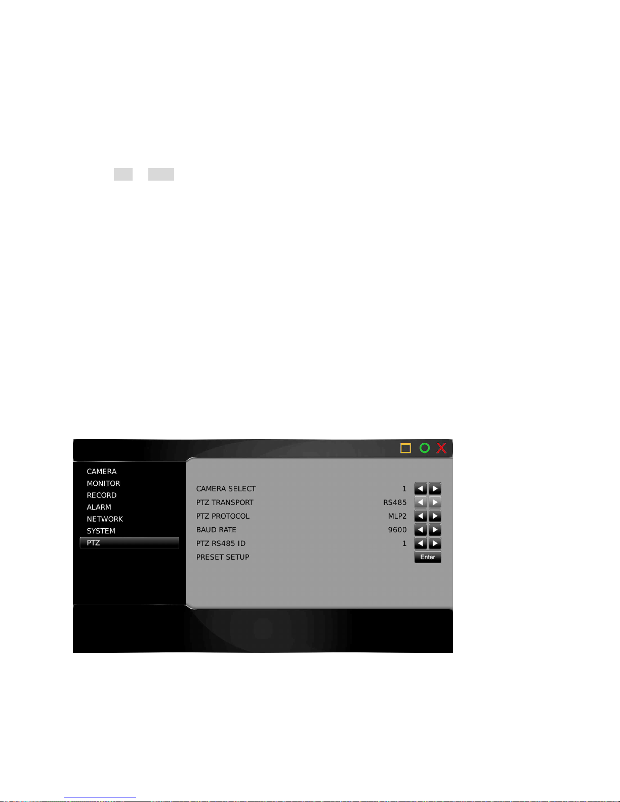
1.7 PTZ setup
The DVR can control RS-485 PTZ or IP PTZ cameras. To setup PTZ connection, follow these
instructions:
1.7-1 Camera select
Use the directional arrows to select the camera you wish to edit
Page 56
DVR User Manuel 55
1.7-2 PTZ transport
Select from ONVIF, HTML or RS-485 transport. If RS-485 is selected the camera must be
connected to the RS-485 output on the back of the DVR.
1.7-3 PTZ protocol
PTZ protocols include MLP1, MLP2, Pelco D, and Pelco P.
1.7-4 PTZ model and baud rate
If the PTZ protocol is transmitted via traditional RS-485 wires attached to the DVR you need to
setup the baud rate and RS-485 ID respectively.
Table below shows listed models in the PTZ protocol list:
Model Baud Rate Number of Bytes
PIH-7000 (MLP1) 9600 3
PIH-7600 (MLP1) 9600 3
PIH-7625-3 (MLP1) 9600 3
PIH-7625-7 (MLP2) 9600 7
PIH-7622-7 (MLP2) 9600 7
Pelco D 2400~9600 None
Pelco P 2400~9600 None
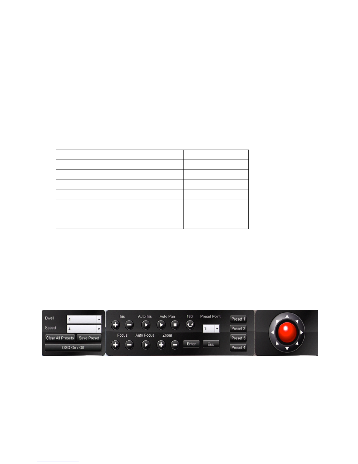
1.7-5 Preset setup
All features of PTZ can be configured from the live menu. You can also enter preset positions
through the preset set up option in the PTZ menu
Setting preset
Enter the preset setup then select your desired preset point from the dropdown bar
Enter dwell
Define the dwell time of a preset using the dropdown menu to select desired time. Dwell
number ranges from 0 to 255 seconds (the shortest to the longest).
Page 57

DVR User Manuel 56
Speed
Define the speed of the previous preset to the next preset, using the dropdown menu to select
desired time. The speed number ranges from 1 to 8 (the slowest to the fastest). The speed
might vary based on different PTZ camera’s settings.
Position
Use the joystick/controller to adjust the preset PTZ to your desired location
Iris and auto iris
Adjust these settings as required
Focus and auto focus
Adjust these settings as required
Save presets
Once the above parameters are entered, the preset can be saved.
Clear all presets
To clear all the preset points of a PTZ camera, select ‘Clear All Presets’ and press Enter key on
the front panel or remote control.
Direct keyboard access
Direct keyboard Access mode allows RS-485 protocol to be directly transmitted to the RS-485
PTZ device
The DVR no longer handles the conversion of the RS-485 protocol
This enables the user to access the PTZ menus using the connected keyboard
Page 58
DVR User Manuel 57
2. Web-based Viewing/Setup
There are two ways of remotely accessing the DVR:
1. Via a network through your Internet browser
2. Via CMX software (for CMX setup see CMX manual)
Live monitoring, menu setup, video playback, and file backup can be done by using your Internet
browser.
2.1 Before using Internet browser
Add DVR IP address to trusted sites
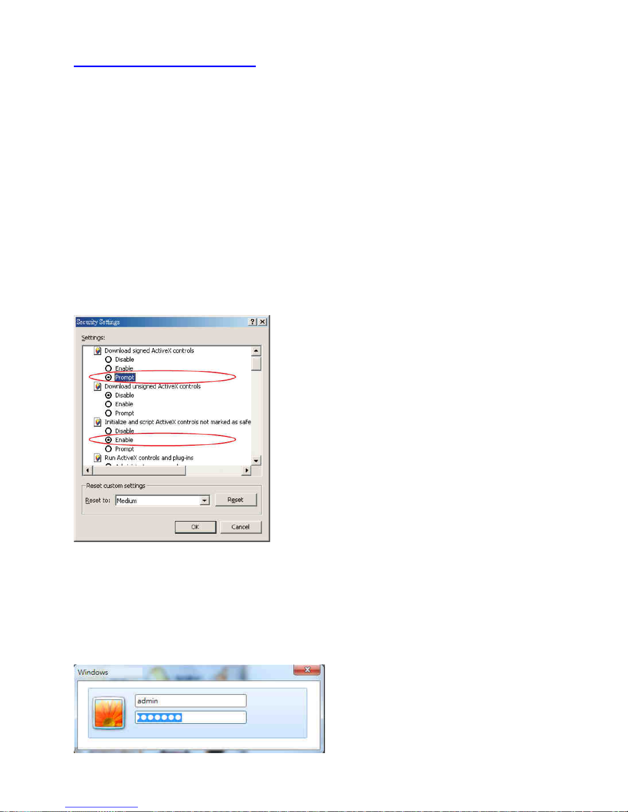
Make sure that your Internet browser allows signed ActiveX plug-in to run on your PC
Set “Download Signed ActiveX plug-in controls” to “Prompt” and “Run ActiveX control and plug-
in” to “Enable” in your internet security options.
To access these, open Internet Explorer > Tools > Options > Security Settings > Custom Level.
2.2 Logon
Type in the DVR’s IP address in the HTTP address box via Internet browser
A log on screen will appear, enter your user name and password
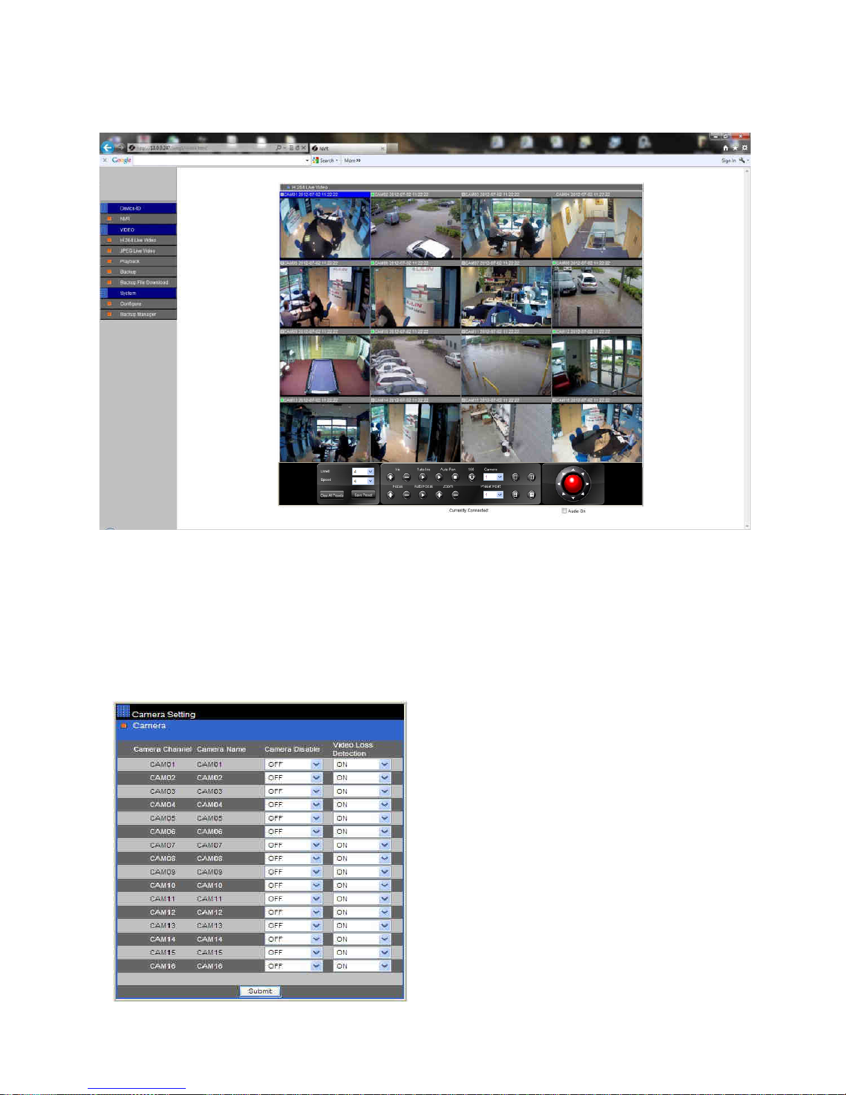
Page 59
DVR User Manuel 58
Once entered the DVR home page will appear:
2.3 Configuring the DVR via web page
Features of the DVR’s main menu system can be configured via web interface. Features such as
camera, alarm, recording, network, and backup can all be set up remotely
2.3-1 Camera setting
Page 60
DVR User Manuel 59
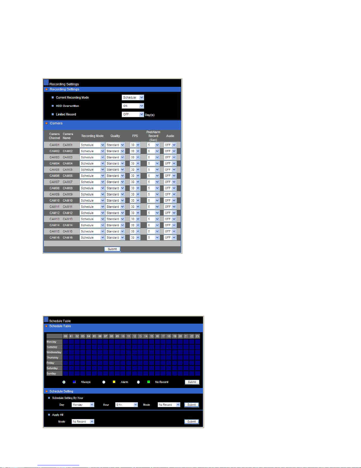
• Camera Enable—enable or disable live video on main monitor
• Video Loss Detection—enable or disable video loss detection
2.3-2 Recording setting
• Current Record Mode—current DVR
recording mode
• HDD Overwritten—option for circular
recording
• Camera Recording Mode--assign
schedule recording or no recording
for a camera
• Camera Quality—setup the recording
quality for a camera
• Camera FPS—recording frame rate
for a camera
2.3-3 Recording schedule table
Users can setup the record schedule table via the Internet browser by specifying the day and
time for the recording mode
Page 61
DVR User Manuel 60
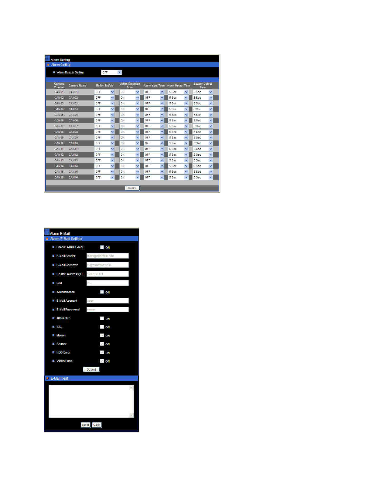
2.3-4 Alarm setting
• Alarm Buzzer Setting—
enable/disable DVR buzzer
• Motion Enable—
enable/disable motion
detection
• Motion Detection Area—
enable/disable motion
detection area
• Alarm Input Type—set alarm
input as NO/NC or disable
• Alarm Output Time—assign
alarm time for each camera
• Buzzer Output Time—assign
buzzer time for each camera
2.3-5 Alarm e-mail
• Enable Alarm Email—option for enable alarm/motion
email
• From—from email address
• To—to email address
• Host/IP Address—SMTP mail server’s IP or DNS
address
• Authentication—option for user and password
authentication
• Email Account—senders email account
• Email Password—senders email account’s password
• JPEG File—option for the enable JPEG file attachment
• SSL—option for the enable SSL attachment
• Motion—option for the enable Motion attachment
• Sensor—option for the enable Sensor attachment
• HDD Error—option for the enable HDD Error attachment
• Video Loss —option for the enable Video Loss
attachment
• Email Test—simple the Email function testing
Page 62
DVR User Manuel 61
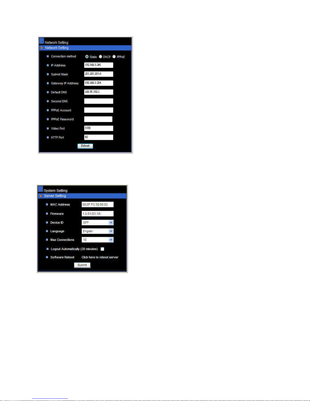
2.3-6 Network setting
• IP Address—DVR’s IP address
• Subnet Mask—subnet mask
• Gateway IP Address—router/Gateway IP
address
• PPPoE account—PPPoE protocol account name
• PPPoE password—PPPoE password
• Video Port—the DVR’s video port
• HTTP Port—HTML port number
2.3-7 System setting
• MAC Address: MAC address of the DVR
• Firmware: firmware version of the DVR
• Device ID: addressable DVR ID for multiple
DVRs remote control using remote controller and
RS-485 keyboard
• Language: language selection of the DVR
• Max Connections: maximum network
connections allowed for the DVR
• Force to Logout: force to logout remote access
• Software Reboot: software reboot of DVR system
Page 63
DVR User Manuel 62
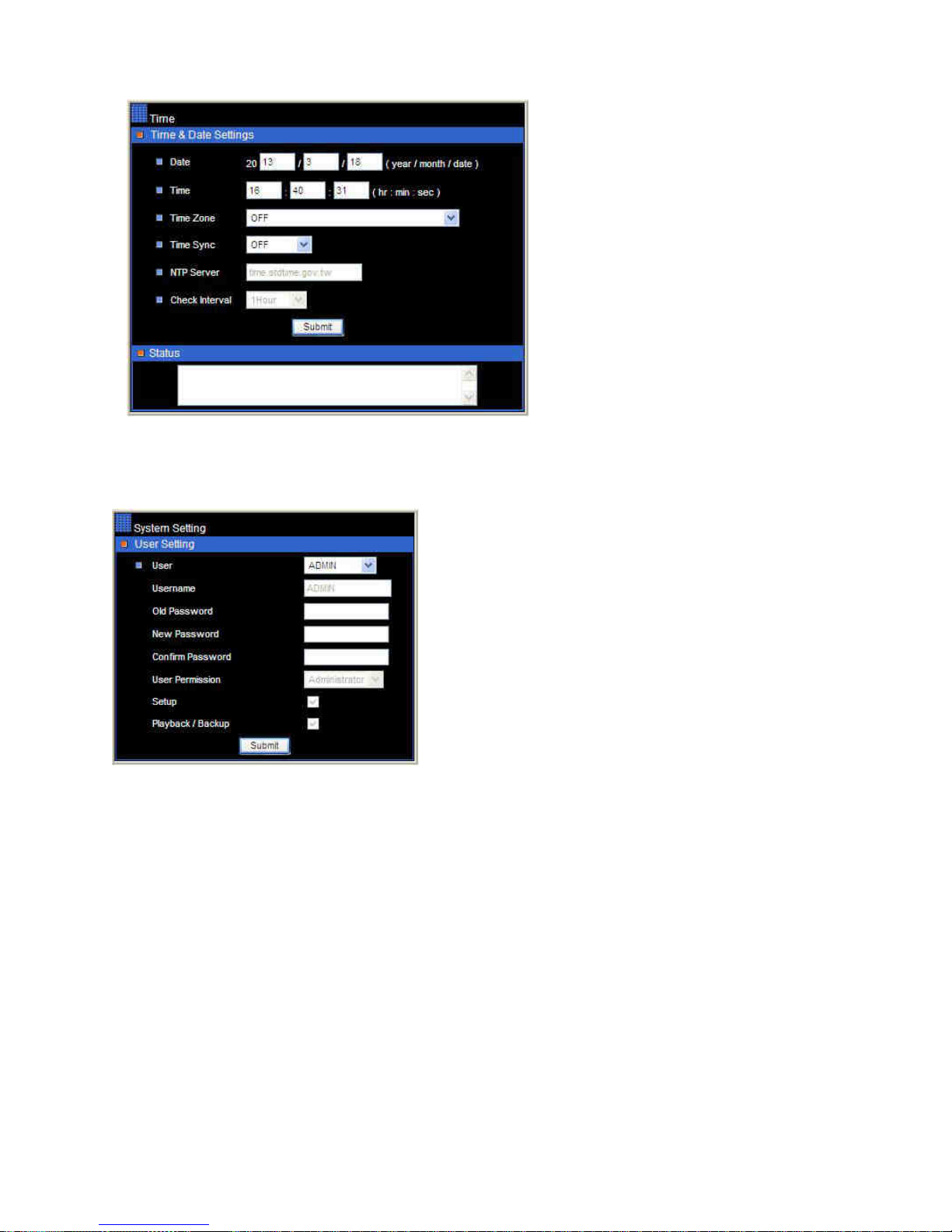
2.3-7-1 Time
• Date: Current date of the DVR
• Time: Current time of the DVR
2.3-7-2 User setting
• There are three levels (admin, operator and
guest) of user authentication allowed in the DVR.
• To change password, specify the old password,
new password, and confirm password, edit as
required.
Page 64
DVR User Manuel 63
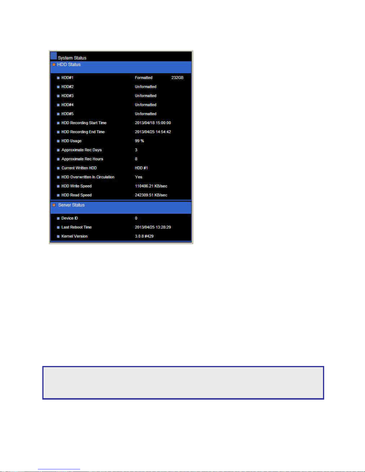
2.3-7-3 System status
• HDD(s)—HDD(s) detecting status
for the DVR
• HDD Recording Start—start
recording time of the DVR
• HDD Recording End – end recording
time of the DVR
• HDD Percentage – recording
percentage of the DVR
• Approximate Rec Days—total
recording hours available for the
HDD(s)
• Approximate Rec Hours—total
recording days available for the
HDD(s)
• Current Written HDD—the HDD of
the DVR in writing
• Already Overwritten—the HDD(s)
has been overwritten.
• HDD Writing Speed—HDD writing
speed detector
• HDD Reading Speed—HDD reading
speed detector
• Device ID—DVR ID/RS-485 ID
• Last Reboot Time – last time for
rebooting the DVR
• Kernel— OS version of the DVR
2.3-7-4 Firmware update
This DVR is set to perform firmware upgrade via network. After the DVR receives the firmware, it
starts to perform firmware upgrade automatically. After finishing the firmware update, the HTML
page will reload. The user can then continue to operate the DVR.
To perform network firmware update, click on Browse button and locate the firmware.
Note: Ensure there is a good connection whilst attempting a firmware update. Failure in the
network connection could result in firmware update failure and the unit may become nonoperational.
Page 65
DVR User Manuel 64
Appendix A
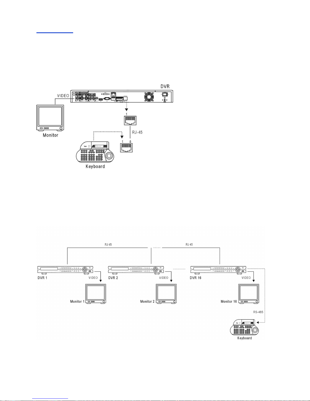
1. Connection between a DVR and a RS-485 keyboard
Directly connect the keyboard to the DVR’s keyboard input using an RJ-45 cable. The DVR
provides 12V DC for the keyboard. There is no need to connect to your power adapter.
A DVR & A Keyboard connection diagram
2. Connections of multiple between DVRs and a RS-485 keyboard
To connect a keyboard with multiple DVRs , connect the RJ-45 cable from keyboard to the DVR’s RJ-45
keyboard input. There are up to 255 DVRs can be connected and addressed.
Page 66
DVR User Manuel 65
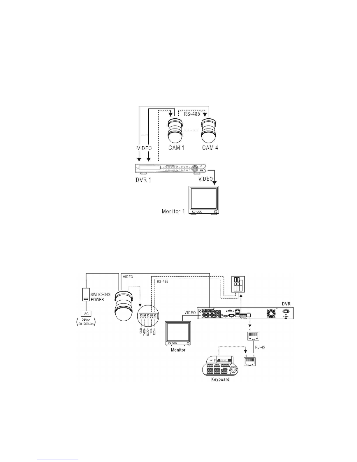
3. Connections between a DVR and multiple RS-485 PTZs
Please use twisted pair cable to connect a PTZ to a NDR. The connections between PTZs,
please refer PTZs’ user manual.
A DVR & PTZs System Diagram
A DVR & PTZs Connection Diagram
Page 67
DVR User Manuel 66
Appendix B
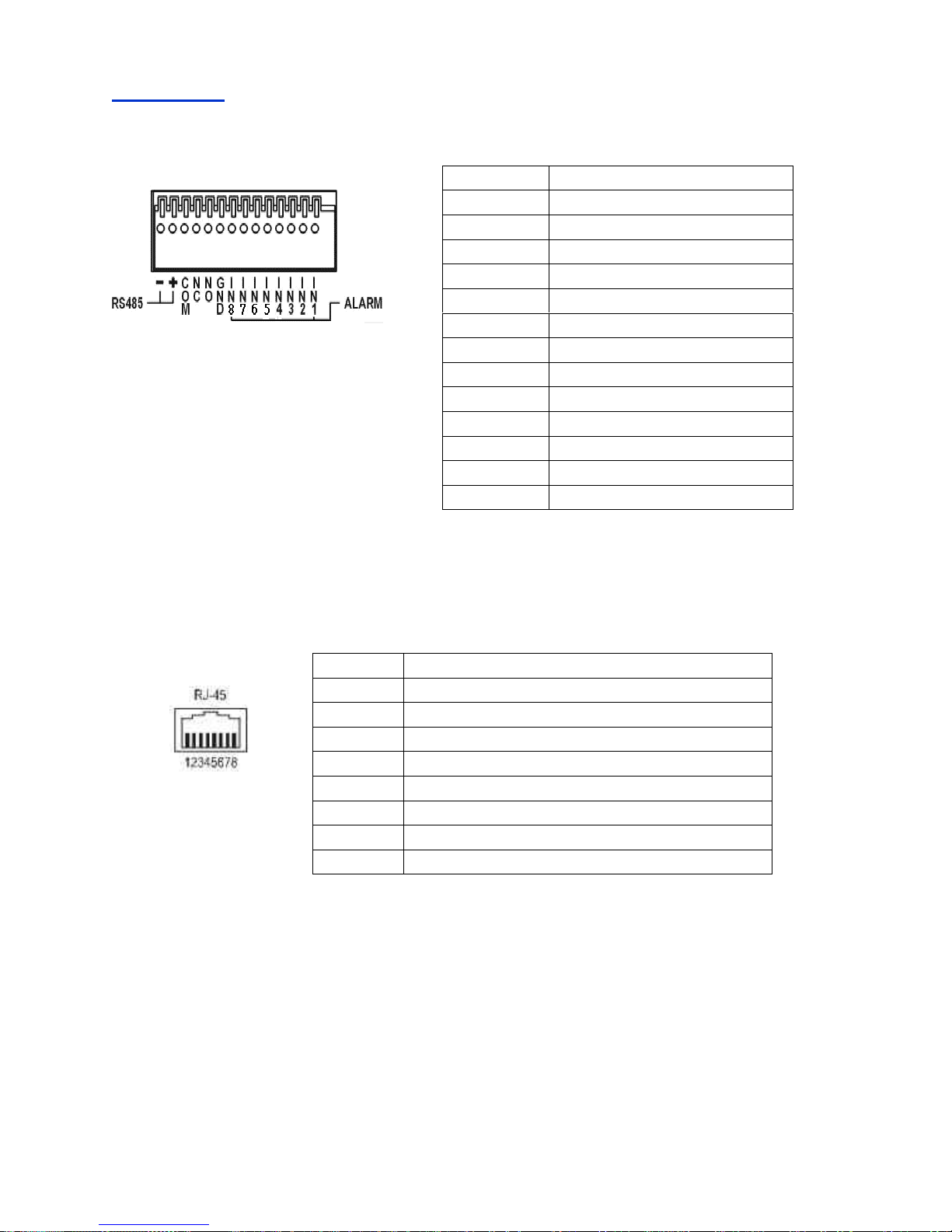
1. Alarm I/Os and RS-485 for PTZ
2. RS-485 Input and Output Pin Assignment
Pin 1 Alarm input 1
Pin 2 Alarm input 2
Pin 3 Alarm input 3
Pin 4 Alarm input 4
Pin 5 Alarm input 5
Pin 6 Alarm input 6
Pin 7 Alarm input 7
Pin 8 Alarm input 8
Pin 9 GND
Pin 10 ALARM NO (normal open)
Pin 11 ALARM NC (normal close)
Pin 12 COM
Pin 13 RS485+
Pin 14 RS485-
Terminal Name
1 -2 -3 -4 -5 RS-485 – Out Link Keyboard
6 RS-485 + Out Link Keyboard
7 GND
8 12V + DC input
Page 68

DVR User Manuel 67
Appendix C
Hard Drive Support List
Brand Model Capacity
WD4000F9YZ 4TB
WD30EURS 3TB
WD20EARX 2TB
WD20EARS 2TB
WD20EURS 2TB
WD20EVDS 2TB
WD15EURS 1.5TB
WD10EZRX 1TB
WD10EARX 1TB
WD10EARS 1TB
WD10EALX 1TB
WD10EURS 1TB
WD5000AVDS 500GB
WD5000AVVS 500GB
WEST DIGITAL
WD3200AVVS 320GB
ST4000DM000 4TB
ST3000DM001 3TB
ST2000DM001 2TB
ST1000DM003 1TB
ST3500418AS 500GB
ST3250318AS 250GB
SEAGATE
ST3160815AS 160GB
HITACHI HDS723020BLA642 2TB
HDS721010DLE630 1TB
Page 69

DVR User Manuel 68
Appendix D
1. Supported USB-DVD/RW
Manufacturer Model
SONY DRX-S30U-W
LITE-ON eSAU108
LITE-ON eTAU108
LITE-ON eHAU424-01
2. Supported DVD Disk
Brand Specification Capacity Max Speed Note
Melody DVD-RW 4.7GB 4x Rewritable
RiTEK DVD-RW 4.7GB 8x Rewritable
Sony DVD+R 4.7GB 8x Burn once
OEM disk DVD-R 4.7GB 8x Burn once
Appendix E
Supported USB Flash Disk
• Transcend: 8G 16G
• Kingston: 4G 8G 16G
• Sandisk: 8G 16G
Appendix F
Hard Disk Recording Table
Approximate recording days and hours can be found at Menu->System->HDD Info.
Note: Above information maybe inaccurate due to the installation environment.
Page 70
DVR User Manuel 69
Appendix G
Touch Screen Monitor Support List
• Acer T231H
• Dell ST2220T
• Iiyama PLT2451MTS-B 23.6”
• ELO ET2201L
• AOC E2239F
• Dell S2340T
• Planar PXL2430MW
Appendix H
Troubleshooting & FAQ
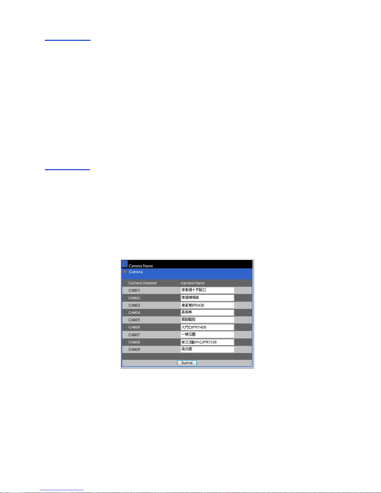
Question: Does the DVR Touch series provide unicode (multi-nation) support for camera names?
Answer: Yes, the DVR Touch series provides unicode for camera names. To do so, login to DVR
Touch series settings via a browser and open Camera Name section. Here you can edit your
unicode camera name.
Page 71

DVR User Manuel 70
Specification
16CH (2U) 16CH (1U) 8CH
Models
D: Internal SATA HDD * 4
and built-in Slim DVD/RW
-: Internal SATA HDD* 4
-: Internal SATA HDD* 2
eSATA Port Yes, *1
Camera Inputs
960H: 960 * 576 (PAL) 960*480 (NTSC) / D1: 720 * 576 (PAL) 720*480 (NTSC)
Recording
Recording mode External alarm / motion detection/ schedule/ manual
Recording
NTSC: 960H: 240 / D1: 480 FPS/Sec
PAL: 960H: 200 / D1 :400 FPS/Sec
NTSC: 960H/ D1: 240
FPS/Sec
PAL: 960H/ D1: 200
FPS/Sec
Schedule 7 day * 24 hrs time table, recording mode configurable
Backup USB 2.0 flash disk / HTTP file download / Audio supported
DVD/RW Slim DVD/RW None
Playback
H.264 AVC video
Capability
Up to 16 channel
simultaneous playback
Up to 8 channel
simultaneous playback
Speed FR: 2x, 4x, 8x,16x, 32x, 64x / FF:2x, 4x, 8x,16x, 32x, 64x
Compression
H.264 AVC and JPEG
Video Input
BNC * 16 (1Vp-p, 75Ω)
BNC * 8 (1Vp-p, 75Ω)
Camera Name
12 characters
Video Looping
BNC * 16 (1Vp-p, 75Ω)
None
Live Video
NTSC : 480 FPS/Sec
PAL: 400 FPS/Sec
NTSC : 240 FPS/Sec
PAL: 200 FPS/Sec
Video Output
BNC * 2 ( Included Spot monitor)
HDMI/ VGA output Up to 1920 x1080p
Multi-touch Support USB multi-touch screen
Multiplexer Sequence / Freeze
Split screen 4, 8, 9,13,16 4, 9, 13,16 4,9
Digital zoom Up to 64x on live and playback
Spot monitor Yes
Management
Reports Full alarm, configuration, and operation reports exporting over HTTP or USB
Authentication User authentication with feature configurable
Recording day Recording day calculator
Alarm/event DI * 8 and DO* 2 (NO/NC)
Motion Motion grid 20*12 each channel, 8 sensitivities
Event
External alarm, video loss, stop recording, power recovering, motion detection, schedule, logon, HDD
format
Email Alarm notification with JPEG attachments
Accessories Remote controller addressable up to 255DVRs
PTZ protocol LILIN MLP1/ 2 and Pelco D/ P
Coaxial Control
Yes, LILIN MLP2 supporting BNC * 4 (Channel 1~4), equivalent 75 ohm coaxial cable
Keyboards 3D keyboard
IR receiver Extra IR extension connector
RS-485/RS-232 RS-485 keyboard connector, Input and output *2, 12V output, RS-485 PTZ output *1
Jog & Shuttle FF, FR, Step, instant rewind, menu setup None
Mouse USB, mouse-click, mouse scroll, mouse drag
Audio
G.711 audio, 0.7Vp-p, 16KHz
Audio out
RCA 16 in , 1 output
RCA 4 in , 1 output
Remote control Yes
MIC Input Yes
Line Out Yes
Network Port Gigabit LAN, RJ45 *1
Network Direct Internet browser access / multiple users access
Protocols
ARP / TCP/IP / UDP / HTTP / SMTP / FTP / DDNS / PPPoE / DynDNS / NTP/ UPnP/ Network Places
Web Live / event log & time search playback / AVI
DVR status HTMLDVR status
Browser
Internet Explorer 7.0 or above, FireFox and Chrome
IP Scan IP Scan supported, automatically quick IP address setup for IP cameras and DVRs
Software
Backup Manager Multiple DVRs FTP file download and multi-channel playback
Mobile phone iPhone, iPad and Android mobile phone supported
Others
WDT Hardware watchdog timer
DST Daylight saving time
Multilanguage
English, Chinese, French, Germany, Italy, Spanish,
Swiss, Norwegian, Arabic, Japanese, Germany,
French, Polish, Portuguese, Simplified Chinese, Vietnam, Italian
CPU/OS
32-bit RISC Processor, Dual Core ARM9 SoC 1G MHz, Linux 3.0.8 kernel
Power DC 12V, 6.67A / 80W DC 12V, 5A / 60W
Working Env. Temp: 0℃ ~ +45℃ / Humidity: 0%~80%
Dimension
434mm * 411.4mm * 88mm
434mm * 364.3mm * 52.8mm
Weight
5.2 Kg w/o HDD
4.7Kg w/o HDD
Page 72

DVR User Manuel 71
DISTRIBUTOR:
 Loading...